Sviluppo e caratterizzazione di materiali ceramici per l'ossidazione diretta di idrocarburi in celle a combustibile ad ossidi solidi operanti a temperature intermedie
110
0
0
Testo completo
(2) That from which is everything that exists (ἅπαντα τὰ ὄντα) and from which it first becomes (ἐξ οὗ γίγνεται πρῶτου) and into which it is rendered at last (εἰς ὃ φθείρεται τελευταῖον), its substance remaining under it (τῆς μὲν οὐσίας. ὑπομενούσης), but transforming in qualities (τοῖς δὲ πάθεσι μεταβαλλούσης), that they say is the element (στοιχεῖον) and principle (ἀρχήν) of things that are. For it is necessary that there be some nature (φύσις), either one or more than one, from which become the other things of the object being saved. Aristotle's Metaphysics 983 b6 8-11 Thales of Miletos (Θαλῆς ὁ Μιλήσιος, ca. 624 BC–ca. 546 BC),. 2.
(3) INDEX. Preface....................................................................................................................................................................... 4 ACKNOWLEDGEMENTS..................................................................................................................................... 5 Chapter 1 ................................................................................................................................................................... 6 INTRODUCTION .................................................................................................................................................. 6 Significance of this Research.............................................................................................................................. 6 Overview of the Upcoming Chapters................................................................................................................. 7 Keywords ............................................................................................................................................................. 7 Chapter 2 ................................................................................................................................................................... 8 STATE-OF-ART (Background).............................................................................................................................. 8 Principle of operation.......................................................................................................................................... 8 Configurations for SOFC .................................................................................................................................. 10 Materials for SOFC ........................................................................................................................................... 11 Cathode (air electrode) ......................................................................................................................................... 11 Electrolyte......................................................................................................................................................... 16 Oxygen ion conductors ......................................................................................................................................... 18 Ceramic proton conductors .................................................................................................................................... 22 Anode (fuel electrode) .......................................................................................................................................... 25 Interconnection ................................................................................................................................................... 30 Sealant............................................................................................................................................................. 36 World wide factories overview .......................................................................................................................... 39 Chapter 3 ................................................................................................................................................................. 46 THERMODINAMICS and KINETICS of SOFCs ........................................................................................ 46 SOFC characteristics......................................................................................................................................... 47 Efficiency........................................................................................................................................................... 56 Internal reforming and direct oxidation .......................................................................................................... 59 Triple Phase Boundary - TPB .......................................................................................................................... 61 Chapter 4 ................................................................................................................................................................. 65 EXPERIMENTAL PART ..................................................................................................................................... 65 Preface ............................................................................................................................................................... 65. CHARACTERIZATION OF SOLID OXIDE FUEL CELL MANIFACTURED BY A EUROPEAN TRADE .............................................................................................................................................................. 68. I n t r o d u c t i o n ................................................................................................................................................. 68 Experimental ..................................................................................................................................................... 68 SOFC Architecture ............................................................................................................................................ 68 Results and discussion...................................................................................................................................... 70 Physic-chemical analysis on the fresh cell................................................................................................................... 70 Electrochemical investigations ................................................................................................................................ 71 Physico-chemical analysis on post-mortem cell ............................................................................................................ 76 Conclusions ....................................................................................................................................................... 77 PROPANE CONVERSION OVER A RU/CGO CATALYST AND ITS APPLICATION IN INTERMEDIATE TEMPERATURE............................................................................................................ 78 I n t r o d u c t i o n ................................................................................................................................................. 78 Experimental ..................................................................................................................................................... 79 Ru/CGO catalyst .............................................................................................................................................. 79 Catalytic activity................................................................................................................................................. 80 SOFC characterization........................................................................................................................................ 80 Results and discussion...................................................................................................................................... 82 Physico-chemical analysis of the Ru/CGO catalyst .................................................................................................... 82 Steam reforming process........................................................................................................................................ 83 Electrochemical investigations ................................................................................................................................ 85 Direct oxidation versus reforming ........................................................................................................................... 91 Conclusions ....................................................................................................................................................... 92 INVESTIGATION of COMPOSITE Ni-DOPED PEROVSKITE ANODE CATALYST for ELECTROOXIDATION of HYDROGEN and LIGHT HYDROCARBONS in SOLID OXIDE FUEL CELLs................................................................................................................................................................ 93 I n t r o d u c t i o n ................................................................................................................................................. 93 Experimental ..................................................................................................................................................... 96 Results and discussion...................................................................................................................................... 97 Conclusions ..................................................................................................................................................... 105 Future planning............................................................................................................................................... 106. 3.
(4) Preface This thesis is submitted for the ‘PhD’ in Materials for Environment and Energy at the University Tor Vergata in Rome. The work was carried out at the Institute of Advanced Technology for Energy of the Italian National Research Council (CNR-ITAE “Nicola Giordano”), under the supervision of Dr. Antonino S. Aricò as tutor. The research was financed by MIUR.. 4.
(5) ACKNOWLEDGEMENTS There are several people that I would like to thank. First of all I would like to thank my supervisor, Dr. Antonino S. Aricò of the CNR-ITAE; I have had the privilege of working with him in the past four years. Dr. Aricò has helped me to overcome problems, giving me substantial insights into the field of electrochemistry and skilful, reliable guidance during my PhD project. He dedicated time and effort, much more than expected, to listen my difficulties and help me in learning and succeeding. Secondly, I would like to thank Dr. Vincenzo Antonucci, who was always willing to listen and always had an open door. Their flexibility, friendliness and encouragement made completing my work at the CNR-ITAE very pleasant and rewarding. Third, I would also like to thank my coordinator, Prof. Enrico Traversa for the efforts he put into my work. I would like to thank Mr. Giuseppe Monforte and Mr. Maurizio Minutoli for their patience in the laboratory experiments shared with me, and Ing. Giovanni Brunaccini for his availability to repair the out of order instruments. Thanks go to Dr. Isabella Nicotera for her NMR analysis and Prof. PierLuigi Antonucci for the catalytic activity measurements. I would like to thank all my friends in the office for their support and friendship, especially Francesco Sergi, Stefania Siracusano, Ruben Jacopo Ornelas and Fabio Matera. At the same time, I also want to thank the whole CNR-ITAE colleagues for the relaxing breaks and funny discussions that made the workplace enjoyable. I would like to pay a special thank to Dr. Daniela La Rosa for the productive collaboration I had with her during my PhD. She spent an enormous amount of time helping me in every aspect of my research and professional life. Thank you Daniela, you must know that working with you was always fun. Good lucky for your career! Gratitude goes to any person who actually reads this thesis with enthusiasm and interest. And finally I would like to thank my family for their support throughout my time as a graduate student and for providing an environment of encouragement that was for me of great support.. 5.
(6) 1 INTRODUCTION Significance of this Research. T. he current energy supply system, which is based on the combustion of fossil fuels, causes many environmental problems: air pollution, acid gas emissions, and the emission of greenhouse gases. At the same time supply of electricity. and transport of goods/persons are the basis of modern life. These two sectors are strongly related to mass consumption of energy. The increasing energy demands and emerging energy crisis pose the question on how energy can be used in the earth more efficiently while keeping our living space clean. An urgent and continuing problem in the 21st century will be how to conserve energy resources and how to decrease the emission of CO2. This problem can be translated as how to eliminate the mass consumption of. energy in developed countries and how to build the most advanced/efficient energy system in the developing countries. This requirement can be summarized as ‘‘highly efficient technology in electricity generation and transportation sector.’’ Solid-state ionic devices, such as SOFCs are promising energy conversion and storage technologies that could solve some environmental issues, while simultaneously curbing the consumption of resources and providing employment opportunities. Solid oxide fuel cell (SOFC) is expected to play a major role in the stationary generation of energy as well as in transportation in the coming decades. The solid oxide fuel cell is currently attracting tremendous interest because of its huge potential to enhance energy conversion efficiency, reliability and security, and reducing environmental impact. As well as, fuel flexibility is one of the significant advantages of solid oxide fuel cells (SOFCs) over other types of fuel cells The major drawback in commercializing SOFCs is concerning with high costs which result from the use of special high temperature ceramic materials. There is considerable interest in lowering the operating temperature from 950°C to 700-800°C, in particular, to reduce the cost of. 6.
(7) interconnects, manifolding and sealing materials, as well to preclude the potential problem resulting from the sintering of electrode particles over time. Although significant advances have been achieved in the development of materials with improved ionic and electronic conductivity and of manufacturing processes to fabricate thinner electrolytes to reduce ohmic losses, the performance at low temperatures is severely limited by interfacial polarization resistance at the cathode/electrolyte interfaces. Design and fabrication of functional, porous, nanostructured electrode to maximize the area of the three-phase boundary (TPB) between ionic, electronic conductor and oxygen gas, remain at the forefront of fuel cell research and development. Nonetheless, considerable work remains to be done to study anodic catalysts with ability to work properly in the presence of a wide range of hydrocarbon fuels and with good performance under redox cycling. This work addresses mainly these aspects i.e. direct oxidation of hydrocarbons at intermediate temperatures.. Overview of the Upcoming Chapters The thesis begins with the state - of - art chapter that introduces a general review of the SOFCs, the challenges of the current research and an outline of the work carried out to achieve the goal. Chapter 3 gives the basics of operations and working conditions of SOFCs including their thermodynamic and kinetic aspects influencing the performances. This chapter discusses the fundamental concepts of fuel cells concentrating on the underlying chemical and electrochemical processes in the upstream condition. Experimental work, results and discussion are described in Chapter 4. In this chapter materials, mechanism and related electrochemical and catalytic properties are investigated.. Keywords: Intermediate temperature solid oxide fuel cells (IT-SOFCs), propane electrooxidation, LSCF, CGO. 7.
(8) 2 STATE-OF-ART (Background) Principle of operation. A. Solid Oxide Fuel Cell (SOFC) is an energy conversion device that produces. electricity by electrochemically combining a fuel and an oxidant across an ionic conducting oxide electrolyte, the principles of operation are illustrated in. Fig. 1. The dense electrolyte is sandwiched between two porous electrodes, the anode and the cathode (the anode/electrolyte/cathode sandwich is referred to as a single cell). Fuel is fed to the anode, undergoes an oxidation reaction, and releases electrons to the external circuit. Oxidant is fed to the cathode, accepts electrons from the external circuit, and undergoes a reduction reaction. The electron flow in the external circuit from the anode to the cathode produces electricity. The difference in oxygen activity of the two gases at the electrodes provides a driving force for motion of the oxide ions in the electrolyte. Oxide ions formed by dissociation of oxygen at the cathode under electron consumption migrate through the electrolyte to the anode where they react with the oxidation products to form water and CO2. The electrochemical reactions occur in the electrodes within a distance of less than 10-20 microns from the electrolyte surface [1, 2]. This zone is referred to as the functional layer. The part of the electrode exceeding this thickness is primarily a current collector structure, which must be porous to allow gas access to the functional layer. The electrolyte has to be gas impermeable to avoid direct mixing and combustion of the gases. The electrolyte is ceramic, and the electrodes are also based on ceramic materials. Under cell operating conditions, the cell produces current as long as the reactants are provided to the electrodes. An open circuit voltage of about 1 volt is attained when the. M. Juhl, S. Primdahl, C. Manon and M. Mogensen, J. Power Sources 61, 173, 1996. M. Brown, S. Primdahl and M. Mogensen, ‘Structure/performance relations for Ni/YSZ anodes for SOFC’, J. Electrochem. Soc. 147, 2, 475-485, 2000.. 1 2. 8.
(9) cell is not loaded, as determined by the Nernst equation which will be discussed in the next chapter.. Fig. 1. A Solid Oxide Fuel Cell. SOFCs provide many advantages over traditional energy conversion systems including high efficiency (in the range 45-60%), reliability, modularity, and extremely low emissions of major local air pollutants (CO, NOx, and unburned hydrocarbons). A SOFC converts the chemical energy of fuel directly into electrical energy. Thus the usual losses involved in the conversion of fuel to heat, to mechanical energy, and then to electrical energy of conventional combustion systems are avoided. SOFCs can potentially be operated on a range of fuels, including pipeline natural gas and bio-mass, without a significant loss of efficiency or increase in system complexity and cost. Furthermore, because of their high temperature of operation (500-1000°C), natural gas can be reformed within the cell stack eliminating the need of an expensive, external reformer. Rather tight limits on fuel sulphur contents are nevertheless still required. In adding, SOFC are characterized by high temperature exhaust gases which could be used in combined cycles. Not least, quiet, vibration free operation of solid oxide fuel cells also eliminates noise usually associated with conventional power generation systems. Among fuel cell types, only the SOFC has the recognized potential to achieve power generation efficiencies in excess of 70% using a hybrid cycle that is both simple and dry, i.e., the SOFC/Gas Turbine.. 9.
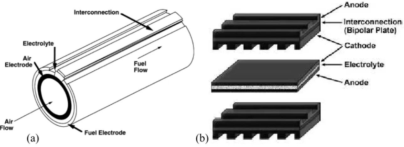
(10) Configurations for SOFC SOFCs have been tested since 1930 under several configurations among which the most widespread and tested are the planar and tubular arrangements. However, a number of technological problems still need to be solved, basically related to the high operating temperature and then to thermal cycling issues. Research and development are therefore still proceeding both to test new materials and to optimize the design of single cells and complete stacks as well. The materials for cell components in these different designs are either the same or very similar in nature. Fig. 2 (a) illustrates the design of the tubular geometry cell developed by Westinghouse [3] and (b) illustrates the planar designs. The materials for different cell components have been selected based on the following criteria. (a) Suitable electrical conducting properties required by different cell components to perform their intended cell functions. (b) Adequate chemical and structural stability at high temperatures during cell operation as well as during cell fabrication. (c) Minimal reactivity and interdiffusion among different cell components. (d) Matching thermal expansion among different cell components.. (a). (b). Fig. 2. Schematics of SOFC designs. (a) Tubular design developed by Westinghouse. (b) Planar design most used today. In addition to the above materials selection criteria, the fabrication processes have been chosen in such a way that every sequential component fabrication process does not affect 3. S.C. Singhal, K. Kendall, High Temperature Solid Oxide Fuel Cells, Elsevier, New York, 2003.. 10.
(11) those components already fabricated and to minimise the cell fabrication cost. The fabrication routes for the individual cell components of SOFC differs greatly depending on which cell component is to perform the supporting function in the cell. Whereas, in most cases the electrolyte or the anode (in case of planar configuration) and cathode (in case of tubular configuration) ensure the mechanical stability of the cells. Common planar cells are shaped rectangularly (square) or circularly. The designs discussed above differ in the current path within a stack of cells, in the gas flow configuration and gas manifolding, and in the cell-to-cell electrical connection.. Materials for SOFC The basic components of a ceramic fuel cell stacks are the electrolyte, the anode, the cathode and the interconnect. The materials for different cell components have been selected based on the following criteria. Cathode (air electrode) The air electrode operates in an oxidising environment of air or oxygen at temperatures between 700-1000°C . It is responsible for the electrochemical reduction of oxygen in the gas phase to oxide ions consuming two electrons in the process as shown in Reaction 1. 1 O2 (g ) + 2e − = O 2− (s ) 2. (1). The oxygen ions formed by reduction then are incorporated into the electrolyte, through oxygen vacancies, and migrate to the anode. In order to function properly, SOFC cathode materials must be catalytically active for the oxygen reduction and have to meet the following requirements. (a) High ionic conductivity is required to facilitate transport of oxygen anions between the electrolyte and active reaction zone. (b) High electronic conductivity is necessary to provide pathways between the reaction sites and external circuit. (b) Chemical and dimensional stability in environments encountered during cell operation and during fabrication of interconnection, electrolyte and fuel electrode layers are required.. 11.
(12) (c) Thermal expansion should match with other cell components. (d) Compatibility and minimum reactivity with the electrolyte and the interconnection is required for the electrodes. (e) Sufficient porosity is necessary to facilitate transport of molecular oxygen from the gas phase to the air electrode / electrolyte interface. In addition to being an electronic conductor, performance and activation overpotential can be significantly improved if the cathode is also an ionic conductor [4, 5, 6]. Since the cathode is constantly in an oxidizing atmosphere, the electrode materials are mostly oxide-based, which typically aren’t known for high electronic conductivities. To satisfy these requirements, doped perovskite oxides of generic formula La1-xAxCo1y. ByO3-δ (A = Sr, Ba, Ca and B = Cr, Mn, Fe, Ni, Cu) and such as lanthanum manganite B. (LSM), lanthanum ferrite/cobaltite (LSFCO) and lanthanum chromite/manganite (LSCM) show reversible oxidation–reduction behaviour. The ABO3 crystal structure type can be described as follows: The A-cations are located at the corners of a cube. O2- ions occupy the face-centred positions and one of the smaller B-cations sits in the centre of the cube. Hence, the B-site cations are surrounded octahedrally by oxide ions. In general, the cation with the larger ionic radius occupies the A-sites, the smaller cation the B-sites. The partial substitution of cations in the ABO3 perovskite structure by cations with a lower valence either leads to formation of oxygen vacancies or to charge compensation by electronic charge carriers. The material can have oxygen excess or deficiency depending upon the ambient oxygen partial pressure and temperature. Large numbers of disordered oxygen vacancies at elevated temperatures may lead to the onset of high ionic conductivity. For example, in the series La1-xSrxCo1-yFeyO3-δ, the ionic conductivity in air at temperatures 700–1000 ºC can be one to two orders of magnitude larger than that of known zirconia-based solid electrolytes [7]. The presence of multivalent cations in the perovskite compositions, on the other hand, ensures a high, often predominating electronic conductivity. In addition to conductivity considerations, the stability and thermomechanical properties of the. 4 E. Koep, D. Mebane, R. Das, C. Compson and M. Liu, “Characteristic Thickness of a Dense La0.8Sr0.2MnO3 Electrode,” Electrochem. and Solid State Lett., 8[11], A592-A595 (2005). 5 E. Koep, A Quantitative Determination of Electrode Kinetics using Micropatterned Electrodes. PhD Thesis, School of Materials Science and Engineering, Georgia Institute of Technology, May 2006. Available at <http://etd.gatech.edu/theses/available/etd-04032006-224453/>. 6 E. Koep, C. Compson, M. Zhou and M. Liu, “A Photolithographic Process for Investigation of Electrode Reaction Sites in Solid Oxide Fuel Cells,” Solid State Ionics, 176, 1-8 (2005). 7 Y. Teraoka, H.M. Zhang, K. Okamoto and N. Yamazoe, Mater. Res. Bull. 23, 51-58 (1988).. 12.
(13) materials are dictated by the choice of cation. A balance must be necessary between the desire for high flux and considerations of long term stability. Typical data of oxygen nonstoichiometry for some simple perovskite oxides are shown in Fig. 3. As can be seen the substitution of trivalent lanthanum by divalent strontium ions in La1-xSrxFeO3-δ is charge compensated by the formation of p-type charge carriers (Fe4+) at relatively high oxygen partial pressure, whereas compensation at oxygen partial pressures corresponding to the plateau in the (3-δ) sub-stoichiometry versus log(pO2) plot occurs predominantly by formation of oxygen vacancies. Oxygen vacancies that are generated upon further decreasing pO2 are predominantly charge compensated by reduction of Fe3+ to Fe2+. In contrast to La1-xSrxFeO3-δ, a pO2 region where the oxygen stoichiometry is virtually constant is lacking in La1-xSrxCoO3-δ[8]. Fig. 3. Data of oxygen nonstoichiometry of some simple perovskite-type oxides at 1273K. Solid lines are results from a fit of the random point defect model to the experimental data.. Current SOFC technologies satisfy these requirements through the use of porous multiphase composite electrodes where, in general, one phase provides ionic conductivity and another electronic. The catalytic activity is usually provided by the electronically conductive phase. The active area of such composite electrodes is inherently restricted to the interfacial regions where these phases meet. Mixed conducting materials can provide both ionic and electronic conductivity in one phase, greatly enhancing the active electrode area. The reaction sites in SOFC electrodes are commonly discussed using the concept of a triple-phase boundary (TPB). The TPB is the location at which the electron conducting, ion conducting and gas phases come into contact.. Proceedings of the 26th Risø International Symposiumon Materials Science: Solid State Electrochemistry Editors: S. Linderoth, A. Smith, N. Bonanos, A. Hagen, L. Mikkelsen, K. Kammer, D. Lybye, P.V. Hendriksen, F.W. Poulsen, M. Mogensen, W.G. Wang Risø National Laboratory, Roskilde, Denmark 2005. 8. 13.
(14) The general macroscopic reaction pathways available for oxygen reduction processes on porous cathode/solid electrolyte structure were already discussed more than 35 years ago [9], and can be summarised in the following diagram (Fig 4) Reaction pathway (1): The oxygen absorbs dissociatively on the surface of the perovskite phase before diffusing along the surface to the triple phase boundary (TPB) where it is incorporated into the ionic phase. Reaction pathway (2): Gas-phase oxygen is incorporated directly into the electrolyte phase at the TPB Reaction pathway (3): This involves incorporation of oxygen at the surface of the mixed ionic-electronic conductor (MIEC) coupled to bulk diffusion to the electrolyte/MIEC interface. Bulk pathway is enabled when the electronic phase is replaced by a mixedconductor. The distance from the interface, λ, where this third mechanism occurs is dictated by a balance between surface exchange rates and bulk ionic conductivity which are related to the vacancy concentration. Low ionic conductivity and fast surface incorporation rates reduces the mechanism to that of the purely electronic conductor. In contrast, high ionic conductivity and low surface rates can extend the reaction zone far from the interface region. Using the characteristic thickness criterion as for MIEC membranes the mixed conducting zone is estimated to extend up to ~10 μm from the interface [10]. At distances greater than this the net current is electronic and only equilibrium exchange occurs between gas phase oxygen and the MIEC. This MIEC zone represents an extension of the TPB region, and increase in active electrode area.. Fig. 4. Schematic showing cathode reaction pathways between ionic, I, electronic, II, and mixed-conducting III materials. (1) surface dissociation and diffusion followed by incorporation at the TPB. (2) direct incorporation at the TPB. (3) incorporation along the length of the MIEC followed by bulk diffusion.. 9. S. Pizzini, in: Fast Ion Transport in Solids, Ed. W. van Gool (North-Holland, 1973) p. 461 S.B. Adler, J.A. Lane and B.C.H. Steele, J. Electrochem. Soc. 143, A3554-A3564 (1996).. 10. 14.
(15) Steele and Bae [11] found that the performance of LSCF-GDC cathodes could be interpreted in terms of surface exchange kinetics; that is that the surface reaction limits the performance. Increased understanding of the relative importance of bulk vs. surface kinetics in MIEC cathodes is required to provide guidelines for both cathode manufacture and the development of new cathode materials. J.A. Lane, et al [12] have obtained information of Oxygen transport and oxygen surface reaction for La0.6Sr0.4Co0.2Fe0.8O3-δ using the conductivity relaxation technique. They have given information on the variation of electrical conductivity of La0.6Sr0.4Co0.2Fe0.8O3- δ with oxygen partial pressure at 800°C. La0.6Sr0.4Co0.8Fe0.2O3-δ, the most thoroughly studied composition in the framework of this thesis, has a rhombohedral structure at room temperature, and shows a phase transition to cubic between 400 and 500°C in air [13]. The expansion of the perovskite lattice upon heating is associated to a major part with the formation of oxygen vacancies (in addition to the usual thermal lattice expansion), and therefore related to the defect chemistry of the material. The behaviour is typical of an acceptor doped perovskite in a mixed electronic ionic compensation regime. Fe3+ and Co3+ play a similar role, and a statistical distribution of the two types of ions on the B-sites in the perovskite lattice is usually assumed [14]. The substitution of La3+ ions on the A-sites of the perovskite lattice by the dopant Sr2+ requires a charge compensation. Electroneutrality can be maintained in two ways: either by a valence change of the B-site cation (creation of holes, electronic compensation) or by the formation of oxygen vacancies (ionic compensation). In general, both processes occur and compete with each other, depending on composition, oxygen partial pressure and temperature. The oxygen nonstoichiometry δ is a function of oxygen partial pressure. At high value of p(O2), the charge is compensated mainly by electron holes, while at lower partial pressures (< 10-3 bar) oxygen vacancies become the dominating defects.. B.C.H. Steele and J.-M. Bae, Solid State Ionics 106, 255-261 (1998). J.A. Lane, S.J. Benson, D. Waller, J.A. Kilner; Solid State Ionics 121 (1999) 201–208 13 S. Wang, M. Kasatoshi, M. Dokiya, and T. Hashimoto, Solid State Ionics 159, 71-78 (2003). 14 S. Wang, M. Kasatoshi, M. Dokiya, and T. Hashimoto, Solid State Ionics 159, 71-78 (2003). 11 12. 15.
(16) Electrolyte The main purpose of an electrolyte is to conduct a specific ion between two electrodes in order to complete the overall electrochemical reaction. Without conduction of that specific ion, no appreciable current would be able to flow through the fuel cell and only potential would exist. With the advancements in fabrication technology, the overall performance of SOFCs is eventually limited by the conductivity of the electrolyte materials. Ideally, an electrolyte is an ionic conductor and an electronic insulator. SOFC electrolytes work in the most stringent environment: hydrogen or hydrocarbons on the anode side, oxygen on the cathode side, and also high temperatures. Solid oxide fuel cells are based on the concept of an oxygen ion conducting electrolyte through which the oxide ions (O-2) migrate from the air electrode (cathode) side to the fuel electrode (anode) side where they react with H2 to form water and electricity. In the case where hydrocarbons serve as the fuel, an oxygen ion conductor offers, in principle, the prospect of direct electro-oxidation: CH 4 + O 2 − → CO2 + 2 H 2O + 8e −. (2). Generally, it is instead presumed that the high temperature of operation associated with oxygen ion conductors can be used to facilitate internal steam reforming:. CH 4 + H 2O → CO + 3H 2. (3). with CO and H2 then used in the electro-oxidation reactions. Even in this more conservative scenario, oxygen-ion conducting electrolytes are preferred because CO can be electro-oxidized, rather than (particularly in the case of low temperature systems) poisoning the anode catalyst. Ceramic proton conductors may offer an interesting combination of benefits because of their ability to transport both protons and oxygen ions. It has been suggested [15] that water can diffuse across the electrolyte membrane, inducing steam reforming and even conversion of CO to CO2 through the water-gas shift reaction:. CO + H 2O → CO2 + H 2. (4). Hydrogen generated by reactions (3) and (4) is then electro-oxidised to form protons. In this case, hydrocarbons can be directly utilized and no water is produced at the anode,. 15. Coors G. J Power Sources 2003;118:150.. 16.
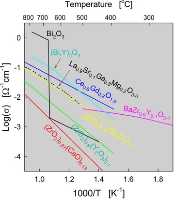
(17) again avoiding dilution effects as fuel utilization increases (although CO2 dilution still occurs). Fundamentally, for optimum cell performance, the electrolyte must be free of porosity so as not to allow gases to permeate from one side of the electrolyte to the other, it should be uniformly thin to minimize ohmic loss, and it should have high ion conductivity with transport number for ions close to unity and a transport number for electrons as close to zero as possible. At the end, electrolytes with these desired properties must be deposited as thin as possible in order to work with low ohmic loss. Conductivity data of a broad range of materials are summarized in Fig. 5 [16, 17,18].. Fig. 5. Conductivities of selected electrolyte materials which are high temperature conductors. The general criteria for the quality of a solid electrolyte material to be used in an SOFC are: (a) Ease of fabrication into a mechanically strong dense membrane of small thickness and large area to minimize bulk resistance. (b) An oxide-ion conductivity σ0 > 10-2 S/cm at the cell operating temperature.. Steele BCH, Mat Sci and Eng 1992;B13:79. Ishihara T, Matsuda H, Takita Y. J Am Chem Soc 1994;116:380 18 Bohn HG, Schober T. J Am Cer Soc 2000;83:768. 16 17. 17.
(18) (c) Excellent chemical and mechanical compatibility with electrodes to avoid formation of blocking interface phases and minimize interfacial resistances. (d) A negligible electronic conductivity at cell operating temperature to retain a transport number close to 1. (e) Compatibility of thermal-expansion coefficients between electrolyte, electrodes, interconnects, and seals from ambient temperature and cell operating temperature. (f) Relatively low costs of material and fabrication.. Oxygen ion conductors The classic oxygen ion conductors are based on fluorite-structured oxide materials such as yttria stabilized zirconia (YSZ) or , rare earth doped ceria (CGO, SDC, YDC), and rare earth doped bismuth oxide. Recently also perovskite oxides such as lanthanum gallate (LSGM), have been widely investigated as electrolytes for a fuel cell [19, 20]. These membranes conduct oxygen ion through oxygen vacancy [21, 22] at high temperature of around 600-1000°C. The oxygen vacancies for a typical tri-valent dopant, M, can be written in the Kröger–Vink notation: M 2 O3 ⎯ZrO ⎯ ⎯2 → 2M Zr' + 3OO× + VO••. (5). with one oxygen vacancy created for every two M atoms incorporated. For both zirconia and ceria, conductivity increases with increasing dopant concentration up to some maximum value and then decreases sharply. Similarly, the conductivity increases then decreases across the rare earth series from Yb to La. For zirconia, Sc gives rise to the highest conductivity, but Y is typically utilized for reasons of cost. With yttrium as the dopant, the conductivity of zirconia peaks at about 8 mole % dopant concentration. The activation energy for oxygen diffusion varies from 0.6 to 1.0 eV depending on the yttria content. J.A. Kilner, B.C.H. Steele, in: O.T. Sorensen (Ed.), Non-stoichiometric Oxides, Academic Press, New York, 1981, p.233. 20 R.M. Dell, A. Hooper, in: P. Hagenmuller, W. van Gool (Eds.), Solid Electrolytes, Academic Press, New York, 1978, p. 291. 21 J.W. Stevenson, T.R. Armstrong, R.D. Carneim, L.R. Pederson and W.J. Webel, Electrochemical properties of mixed conducting perovskite La1-xMxCol-yFeyO3-δ (M=Sr, Ba, Ca), J. Electrochem. Soc., 143 (1996) 2722-2729. 22 L. Shiguang, W. Jin, P. Huang, N. Xu, J. Shi and Y.S. Lin, Tubular lanthanum cobaltite perovskite type membrane for oxygen permeation, J. Membr. Sci., 166 (2000) 51-61. 19. 18.
(19) In the case of ceria, Sm [23] and Gd [24] give the highest values of conductivity, and optimal dopant concentrations are 10–20%. The strong dependence of ionic conductivity on dopant type and concentration has been explained in terms of the lattice distortions introduced by the dopant, with those that produce the least amount of strain causing the smallest variation in the potential energy landscape [25]. Overall, the ionic conductivity of ceria is approximately an order of magnitude greater than that of stabilized zirconia for comparable doping conditions. This is a result of the larger ionic radius of Ce4+ (0.87 Å in 6-fold coordination) than Zr4+ (0.72 Å), which produces a more open structure through which O= ions can easily migrate. Despite its favourable ion transport properties, ceria had not, until quite recently, been considered a realistic candidate for fuel cell applications because of its high electronic conductivity. In particular, under reducing conditions, CeO2 (Fig. 6) is not stable and becomes CeO2-x, and n-type conductivity increases with a P(O2)-1/4 dependence.. Fig. 6. Crystal structure of fluorite exhibited by ceria. Although the strategy gives a transport number t0 ≡ σ0/σ ≈ 1 in air or an inert atmosphere such as argon, Ce3+ ions are created in a reducing atmosphere to give a measurable electronic component σe in the total conductivity σ. From an analysis of relevant literature data, Steele [26] has proposed that the electrolytic domain boundary, the oxygen partial pressure at which electronic and ionic conductivities are equal, can be estimated for 10 and 20% Gd doped ceria.. Eguchi K, Setoguchi T, Inoue T, Arai H. Solid State Ionics 1992;52:165. Steele BCH. Solid State Ionics 2000;129:95. 25 Mogenson M, et al. 2003 (manuscript in preparation). 26 Steele BCH. Solid State Ionics 2000;129:95. 23 24. 19.
(20) In principle, one expects to be well within the electrolytic domain of ceria for fuel cells operated below 700 °C, although even at these temperatures some voltage loss is expected. Reported open circuit potentials for doped ceria are lower than what one would expect on the basis of the electronic conductivity of ceria and represented simply as the multiple of the ionic transference number (greater than ~0.9 [27] at 700 °C and 1018. atm oxygen partial pressure) and the Nernst potential. For Gd0.2Ce0.8O2 (GDC), which. gives the highest oxide-ion conductivity of the rare-earth doped ceria, [28] the open circuit voltage of a hydrogen-air fuel cell was reduced to about 0.89 V at 650ºC[29]. The reasons for this discrepancy are not entirely obvious, but are likely due to electrode (in particular cathode) overpotentials, and emphasize the importance of developing electrodes compatible with ceria that enable theoretical open circuit potentials to be reached. An additional challenge lies with the chemical expansion of ceria under reducing conditions and the internal stress that result [30]. At this stage, the significance of this issue on the long-term viability of ceria-based fuel cells is unknown. It is noteworthy that planar cells experience lower stresses than tubular cells, suggesting that clever designs may alleviate possible stresses. Equation 6 describes the ionic conductivity based upon the migration via oxygen vacancies. ⎛ ΔE ⎞ ⎟ ⎝ kT ⎠. σT = σ 0 exp⎜ −. (6). In this equation ΔE, the activation energy, involves both ΔHm and ΔHa, which are the enthalpy for migration of oxygen and the association enthalpy of defect complexes, respectively. Doping the ceria with certain rare earth oxides can markedly reduce the enthalpy of association. These rare earth oxide are Gd2O3, Sm2O3 and Y2O3. In low pO2 the ceria becomes reduced according to the following process: 1 ' × OO + 2CeCe → VO•• + 2CeCe + O2 ( g ) 2. (7). ' × OO + 2CeCe + H 2 ( g ) → VO•• + 2CeCe + H 2 O ( g ) in hydrogen gas. (8). When ceria is doped with oxides of lower valences, the oxygen vacancy concentration is mainly determined by the concentration of dopant. Milliken C, Guruswamy S. J Am Cer Soc 2002;85:2479. K. Eguchi, T. Setoguchi, T. Inoue, and H. Arai, "Electrical-Properties Of Ceria-Based Oxides And Their Application To Solid Oxide Fuel-Cells." Solid State Ionics 52 (1992) 165-172. 29 C. Lu, W. L. Worrell, R. J. Gorte, and J. M. Vohs, "SOFCs for direct oxidation of hydrocarbon fuels with samaria-doped ceria electrolyte." Journal Of The Electrochemical Society 150 (2003) A354-A358. 30 Atkinson A, Ramos TMGM. Solid State Ionics 2000;129:259. 27 28. 20.
(21) ' Gd 2 O3 ⎯CeO ⎯ ⎯2 → 2Gd Ce + VO•• + 2OO×. (9). In doped ceria equation (7) still takes place. Doping affects however the equilibrium of this reaction, by changing the oxygen vacancy concentration and the concentration of ' . For undoped ceria, the oxygen vacancy concentration is determined by the CeCe. [ ]. ' ' concentration of CeCe i.e. CeCe = 2 VO•• . In doped. [ ]. ceria, VO•• can be assumed to be constant. For undoped and doped ceria the ' concentration of CeCe is given by equation (10) and (11), respectively.. [Ce ] = 1 2 K ' Ce. [Ce ] = 1 2 K ' Ce. ⋅ pO 2. −1. R. ⋅ pO 2. −1. R. 6. for undoped ceria. (10). 4. for doped ceria. (11). The electronic conductivity is caused by polaron hopping. So σe is determined by the ' concentration of the electron carrier, CeCe (see equation (12).. σ e = neμ e. (12). in which e is the elementary charge of an electron and μe is the electron mobility. Eventually the electronic conductivity can be described by equation (13), which has the Arrhenius form, as the electron mobility is temperature dependent. 1 ⎛ ΔH n ⎞ − ⎟ pO2 4 ⎝ kT ⎠. σ nT = σ n0 exp⎜ −. (13). As becomes clear from this equation, the electronic conductivity increases with increasing temperature and decreasing oxygen partial pressure. The electronic conductivity remains, however too low at high temperatures (about 0.16 S/cm at 800ºC). Oxide-ion conducting perovskites have appeared in the literature for several years, but only recently have compositions with conductivities high enough for consideration in fuel cell applications appeared. The ABO3 perovskite structure, Fig. 7, is extremely amenable to tailoring via doping on both the A and B cation sites. A large variety and concentration of dopants can be accommodated in a wide range of host compounds.. 21.
(22) Fig. 7. Crystal structure of perovskite exhibited by oxygen ion conducting LaGaO3 and by proton conducting BaZrO3. Introduction of divalent dopant ions, typically Sr and Mg, onto the La and Ga sites, respectively, of lanthanum gallate produces a material with a high concentration of mobile oxygen vacancies and thereby high oxygen ion conductivity. The transport properties of the particular composition La0.9Sr0.1Ga0.8Mg0.2O3-δ (LSGM) are comparable to those of scandia-doped zirconia. The conductivity is entirely ionic over an extremely wide oxygen partial pressure range at temperatures as high as 1000 °C, but is not as high as that of suitably doped ceria. Thus, the conditions under which LSGM might be preferable to doped ceria appear limited to the temperature range of 700–1000 °C. Moreover, lanthanum gallate suffers from reactivity with nickel, the typical SOFC anode electrocatalyst. To address this challenge, (non-reactive) ceria buffer layers have been incorporated between the electrolyte and the anode [31]. Nevertheless, intensive research efforts to develop SOFCs incorporating lanthanum gallate continue, and recent work suggests that the ionic conductivity can be increased by further adjustments to the stoichiometry, in particular, via the addition of small concentrations of Ni or Co [32].. Ceramic proton conductors In analogy to the defect chemistry of lanthanum gallate, proton transport in barium zirconate, barium cerate and related materials is achieved by first doping the material with a trivalent species (such as yttrium) on the B site so as to introduce oxygen vacancies. 31 32. Huang HQ, Wan JH, Goodenough JB. J Electrochem Soc 2001;148:A788. Ishihara T, Shibayama T, Nishiguchi H, Takita Y. J Mat Sci 2001;36:1125.. 22.
(23) The dopant incorporation reaction is normally assumed to occur as per Eq. (14) (written in Kroeger-Vink notation). ' × 2CeCe + OO× + Gd 2O3 ⇒ 2Gd Ce + VO•• + 2CeO2. (14). Subsequent exposure of the material to humid atmospheres is presumed to lead to the incorporation of protons as per Eq. (15). H 2O ( g ) + VO•• + OO ⇒ 2OH O•. (15). The protons introduced by this manner are generally not bound to any particular oxygen ion, but are instead free to migrate from one ion to the next. This easy migration results in the high proton conductivity (as high as 10-2 Ω-1 cm-1 at 500 °C) observed in these oxides. Much like the oxide conductors, proton conductivity peaks at intermediate dopant concentrations and with suitable matching of the dopant ionic radius to the host structure. Furthermore, proton transport dominates the overall electrical transport to temperatures of approximately 600 °C; the proton transference number of BaCe0.95Sm0.05O3, for example, is ~0.85 at this temperature [33]. At higher temperatures, both oxide ion transport and electron transport become significant. The defect chemistry of doped A2+B4+O3 perovskites is complicated by the possibility that the trivalent ion may reside on both cation sites, and not only the B4+ site as desired [34]. The consequence of partial incorporation of the dopant onto the A2+ site is that fewer oxygen vacancies than anticipated will result. The effect is exacerbated by high temperature processing which can induce BaO evaporation. A second complication arises from the highly refractive nature of the zirconate proton conductors, e.g. doped BaZrO3. In comparison to the cerates (BaCeO3 and SrCeO3), barium zirconate offers high conductivity and excellent chemical stability against reaction with CO2. However, fabrication of dense electrolyte membranes from this material remains a significant challenge. Indeed, the high bulk conductivity of BaZrO3 had, for several years, remained obscured as a consequence of the material’s refractory nature, which results in fine-grained samples with high total grain boundary resistance [35, 36]. In light of the reactivity of cerates with CO2 and the difficultly of fabricating dense zirconate electrolytes, it is perhaps no surprise that few complete cells of protonconducing electrolytes have been constructed and characterized.. Iwahara H, Yajima T, Hibino T, Ushida H. J Electrochem Soc 1993;140:1687. Haile SM, Staneff G, Ryu KH. J Mat Sci 2001;36:1149. 35 Kreuer KD. Solid State Ionics 1999;125:285. 36 Bohn HG, Schober T. J Am Cer Soc 2000;83:768. 33 34. 23.
(24) Thermal expansion of these electrolyte materials is also very important. Table 1 lists the average thermal expansion coefficient (CTE) for candidate SOFC electrolyte materials from 25-800ºC and 25-1000ºC. Since the CTE of the electrolyte material is harder to change without also altering its physical properties, most other SOFC components are chosen and/or designed to match the expansion of the electrolyte.. Material. α*10-6 K-1. α*10-6 K-1. (25-800°C). (25-1000°C). Reference. Y0.15Zr0.85O1.93. 10.5. 10.9. 37, 38. Y0.18Zr0.82O1.91. 10.6. 11. 39. Sc0.15Zr0.85O1.93. 10.3. 10.4. 40. Sc0.18Al0.02Zr0.8O1.9. 10.5. 10.9. 41. Gd0.2Ce0.8O1.9. 12.5. 12.7. 42. Sr0.1Ce0.9O1.9. 12.8. 13.1. 43. La0.8Sr0.2Ga0.9Mg0.1O3-x. 10.4. 10.8. 44. La0.8Sr0.2Ga0.8Mg0.2O3-x. 10.5. 11.3. 45. La0.9Sr0.1Ga0.75Mg0.2Co0.05O3-x. 10.9. 11.4. 46. La0.9Sr0.1Ga0.8Mg0.2O3-x. 12.3. 13. 47. R. Maenner, E. Ivers-Tiffée, W. Wersing, W. Kleinlein, in Proceedings of the 2nd European Ceramics Society Conference, G. Zeigler and H. Hausner eds., Deutsche Keramische Gesellschaft, pp. 2085 (1991). 38 F. Tietz, G. Stochniol and A. Naoumidis, in Proceedings of the 5th European Conference on Advanced Ceramics, Processes and Applications, L.A.J.L. Sarton and H.B. Zeedijk, Nertherlands Society for Materials Science, 2, 271, 1997. 39 F. Tietz, G. Stochniol and A. Naoumidis, in Proceedings of the 5th European Conference on Advanced Ceramics, Processes and Applications, L.A.J.L. Sarton and H.B. Zeedijk, Nertherlands Society for Materials Science, 2, 271, 1997. 40 Y. Mizutani, M. Tamura, M. Kawai and O. Yamamoto, “Development of High Performance Electrolyte in SOFC,” Solid State Ionics, 72[2], 271-275 (1994). 41 F. Tietz, G. Stochniol and A. Naoumidis, in Proceedings of the 5th European Conference on Advanced Ceramics, Processes and Applications, L.A.J.L. Sarton and H.B. Zeedijk, Nertherlands Society for Materials Science, 2, 271, 1997. 42 F. Tietz, G. Stochniol and A. Naoumidis, in Proceedings of the 5th European Conference on Advanced Ceramics, Processes and Applications, L.A.J.L. Sarton and H.B. Zeedijk, Nertherlands Society for Materials Science, 2, 271, 1997. 43 F. Tietz, G. Stochniol and A. Naoumidis, in Proceedings of the 5th European Conference on Advanced Ceramics, Processes and Applications, L.A.J.L. Sarton and H.B. Zeedijk, Nertherlands Society for Materials Science, 2, 271, 1997. 44 F. Tietz, “Innovative Materials in Advanced Energy Technologies,” in Proceedings of the 9th CIMTEC – World Ceramic Congress and Forum on New Materials, P. Vincenzini ed., Techna Publishers S.R.L., Faenza, Italy, 24, 61, 1999. 45 I. Yasuda and M. Hishinuma, in Proceedings of the 64th Annual Electrochemical Society of Japan, Extended Abstracts, Yokohoma, Japan, The Electrochemical Society of Japan, pp. 63, 1997 46 F. Tietz, “Innovative Materials in Advanced Energy Technologies,” in Proceedings of the 9th CIMTEC – World Ceramic Congress and Forum on New Materials, P. Vincenzini ed., Techna Publishers S.R.L., Faenza, Italy, 24, 61, 1999. 47 F. Tietz, “Thermal Expansion of SOFC Materials,” Ionics, 5 129-139 (1999). 37. 24.
(25) Table 1. Thermal expansion coefficients for candidate SOFC electrolyte materials.. Anode (fuel electrode) In the SOFC, the fuel arriving at the anode is generally reducing in nature. Thus, the fuel electrode must be stable in the reducing environment of the fuel, catalytic activity to hydrogen and hydrocarbons oxidation and with high ionic and electronic conductivity over a wide pO2 range. Especially in the anode supported SOFC design it must have sufficient porosity to allow the transport of the fuel to and the transport of the products of fuel oxidation away from the electrolyte / fuel electrode interface where the fuel oxidation reaction takes place, i.e.: O 2− (s ) + H 2 ( g ) = H 2 O( g ) + 2e −. (16). Furthermore, the anode must be characterised by chemical and physical compatibility with surrounding components. Stability and compatibility of the anode applies to both chemical and dimensional/phase changes, which could occur due to interactions with other SOFC components, the highly reducing atmosphere, the byproduct water vapour, CO2 and/or the 450-1000ºC operating temperatures [48, 49]. In order to perform its proper electrochemical functions, the anode must be able to transport oxygen ions to the active oxidation sites as well as product electrons away from the active sites. Since there are no adequate mixed-conducting materials available to perform both functions, ceramic-metallic or ‘cermet’ composites of electronic and ionic conducting materials are used. The reducing conditions present on the fuel side of an SOFC permit the use of a metal such as nickel as the fuel electrode. Alternatively, cobalt or ruthenium and noble metals are good choices as SOFC anode since they have excellent electrical conductivities in reducing atmosphere. Among them, Ni and Cu are the most popular ones owing to excellent catalytic properties for breaking hydrogen bonds, for the low reactivity with other components and they fairly low cost [50]. However, the thermal expansion of nickel is considerably larger than that of YSZ. Nickel can also sinter at the cell operating N.Q. Minh and T .Takahashi, Science and Technology of Ceramic Fuel Cells. Elsevier Science B.V., Amsterdam, The Netherlands, 1995. 49 N.Q. Minh, “Ceramic Fuel Cells,” J. Am .Cer. Soc., 76[3], 563-588 (1993). 50 B.C.H. Steele, ‘Materials for fuel cell technology’, Nature 414, 345-352, 2001. 48. 25.
(26) temperature resulting in a decrease in the fuel electrode porosity. These problems are circumvented by forming a skeleton of electrolyte ceramic around the nickel particles. The ceramic electrolyte skeleton prevents sintering of the nickel particles, decreases the fuel electrode thermal expansion coefficient bringing it closer to that of the electrolyte minimising the TEC mismatch, and provides better adhesion of the fuel electrode with the electrolyte. In addition, it operate to increase the triple phase boundary (TPB). Porosity is engineered into the structure through addition of pore forming agents to the ceramic-metallic composite as well as the increased volume associated with the reduction of NiO to Ni. Percolation theory relates the volume fraction of each component within a composite to the connectivity of those phases. As a rough estimate, for three phases to achieve connectivity within a composite, each should be 33 volume %. The content of anode cermets is traditionally aimed at achieving percolation between the metallic, ionic and porous phases, thus each phase should account for about 33% of the anode structure. Electrocatalysis of hydrogen on metals such as Ni is relatively facile, and anode overpotentials are a small contribution to the overall drop in fuel cell voltage. The rate limiting step is the adsorption of hydrogen onto the metal surface, as opposed to the subsequent reaction of that hydrogen to yield protons and electrons. Nickel is also an excellent catalyst for cracking of hydrocarbons under deposition of carbon. The carbon formation can cause clogging of gas channels, physical disintegration of the nickel structure and fragmentation of the porous anode. Therefore nickel-based anodes are not suitable for direct operation in dry natural gas without modifications of the catalytic properties. Another drawback of nickel is its reactivity at elevated temperature under high partial pressures of water, such as in partially spent fuel gas. Volatile Ni(OH)2 is formed and it exerts a partial pressure of about 10-6 atm at 950°C [51]. This is not itself critical but due to the rapid passage of fuel gas, the formed Ni(OH)2 is swept away, diminishing the long term stability of the anode. Equations 17-22 show the reaction that occur when methane is fed to a Ni-YSZ anode. CH 4+ H 2O → CO + 3H 2. (17). H 2 + O 2 − → H 2O + 2e −. (18). CO + O 2 − → CO2 + 2e −. (19). 51 A. Gubner, H. Landes, J. Metzger, H. Seeg and R. Stübner, SOFC V, U. Stimmimg, S.C. Singahl, H. Tagawa and W. Lehnert Eds., PV97-40, The Electrochem. Soc., Pennington, 540, 1997.. 26.
(27) Steam reforming is associated with the following gas shift reaction, in which carbon monoxide is converted into hydrogen and carbon dioxide:. CO + H 2O → CO2 + H 2. (20). If the steam content in the feed gas is insufficient for reaction 1 to occur, carbon will be deposited according to:. CH 4 → C + 2H 2. (21). 2CO → C + CO2. (22). Based on these drawbacks, the ultimate objectives are the investigation of new Solid Oxide Fuel Cell anodes capable of efficient operation under hydrogen and hydrocarbons and which avoid the problems that the Ni based cermet anode presents. During the past few years a lot of work has been done to investigate alternative anode materials, especially the mixed conducting ceramics like ceria, e.g. doped with gadolinium (GDC). As CeO2 exhibits both ionic and some electronic conduction under reduction conditions, this material can be used for anodes without forming a composite [52]. Nevertheless this material presents a drawback, which is a redox change in volume for ceria as a consequence of part of the present Ce4+ being reduced to Ce3+ under release of oxygen from the lattice. By partially doping with 10 mol% Gd this redox change in volume for ceria is reduced but not eliminated [53]. In recent reports where SOFCs directly utilised hydrocarbon fuels, alternative anode cermet compositions were used introducing metals such as Co, Ru, Cu and alloys of these metals with each other and with Ni, namely, Ni-ceria [54, 55], Cu-ceria [56, 57, 58], Ru-CGO [59]. However, there are still considerable limitations. Ni-ceria is not well suited for use with hydrocarbon fuels because the high Ni content (~50 vol %) promotes coking. Thus Ni-ceria was successfully used only with methane and at relatively low temperatures (~500°C). Moreover, British Gas [60] have examined the steam reforming rates of CH4 over Ni-GDC anodes and obtained activation energy of 0.52 eV while using 52 O.A. Marina, C. Bagger, S. Primdahl and M. Mogensen, ‘A solid oxide fuel cell with gadolinia doped ceria anode: preparation and performance’, Solid Oxide Fuel Cell 123, 199-208, 1999. 53 S. Primdahl, PhD Thesis, University of Twente, The Netherlands, 1999. 54 E.P. Murray, T. Tsai and S.A. Barnett, Nature 400, 649, 1999. 55 E.P. Murray and S.A. Barnett, in Solid Oxide Fuel Cells VI, S.C. Singhal and M. Dokiya Eds., PV 99-19, The Electrochem. Soc. Proc. Series, Pennington, NJ, 1001, 1999. 56 S.D. Park, J.M. Vohs and R.J. Gorte, Nature 404, 625, 2000. 57 R.J. Gorte, S.D. Park, J.M. Vohs and C.H. Wang, Adv. Mater., 12, 1465, 2000. 58 S.D. Park, R.J. Gorte and J.M. Vohs, Appl. Catal. A, 200, 55, 2000. 59 M. Lo Faro, D. La Rosa, G. Monforte, V. Antonucci, A. S. Aricò, P. Antonucci, Journal Applied Electrochemistry, 37 (2007) 203-208 60 British Gas, Investigation of Internal Reforming on Solid Oxide Fuel Cell Anodes. ETSU Report No. F/01/00013/REP. DTI. UK (ETSU, Harwell. Oxon., UK, 1995). 27.
(28) natural gas containing higher alkanes resulted in much higher activation energies (1.5-3.6 eV). Copper is, like nickel, an excellent electronic conductor, but is a poor catalyst towards hydrocarbon cracking. However Cu is not as good electrocatalyst as Ni. Furthermore, Cu has a relatively low melting point, and is thus tricky and limiting the high temperature SOFC fabrication techniques. Another disadvantage of using copper in anodes is the precipitation of Cu-metal between the anode and electrolyte after prolonged SOFC operation. This precipitation decreases the performance of the anode [61]. Stability and performance in hydrocarbon fuels is the single biggest challenge facing anode development. There have been considerable efforts to understand the mechanism of anode poisoning and to improve the design of anodes, such that SOFC performance doesn’t significantly degrade when carbon deposits occur. La Rosa et al. [62, 63] have proposed Ni-Cu alloy combined with ceria for the direct utilization of hydrocarbons. The possibility to use this alloy is owing to the substitution of the Ni-Ni-Ni with Ni-Cu-Ni patterns avoiding the cracking process. In the search for alternative anode materials that are capable to withstand sulfur contamination, volume instability upon redox cycling, and carbon deposition, perovskite oxides have drawn considerable attention. With these materials the catalytic oxidation of hydrocarbons appear to involve lattice oxygen (Mars van Krevelen mechanism), and there is also some evidence that the presence of protonic conductivity can also activate absorbed CH4 molecules [64]. They can be easily substituted on the A and B sites with alkali earth and transition metal elements respectively. This allows interesting modifications of their electronic and catalytic properties. These perovskite materials are reported to be stable at operating temperature of SOFC (600-1000°C) and across a wide oxygen partial pressure range (110-20atm)[65]. Accordingly Steele et al. [66] proposed the following criteria for the selection of alternative oxide anode materials: Gorte, R.J., Vohs, J.M., Journal of catalysis, vol. 216, 2003, p. 477 – 486, Novel SOFC anodes for the direct electrochemical oxidation of hydrocarbons 62 A. Sin, E.Kopnin, Y. Doubitsky, A. Zaopo, A.S. Aricò, L.R. Gullo, D. La Rosa, V. Antonucci, CNR ITAE. Journal of Power Sources 164 (2007) 300-305 63 D. La Rosa, M. Lo Faro, V. Antonucci, A. S. Aricò, G. Monforte, Sin Agusti, 10th Symposium on Solid Oxide Fuel Cells, 2007 64 C.B. Alcock, J. Catal. 140 (1993) 557 65 M. Guilodo, E. Djurado, P. Vernoux ,“Catalytic and Electrochemical Properties of Doped Lanthanum Chromites as New Anode Materials for SOFC”, J. Am. Ceram. Soc. October 2001. 66 B.C.H Steele, P. H. Middleton and R.A. Rudkin, Solid State Ionics 40/41 (1990) 810 61. 28.
(29) 1. Good electronic conductivity, preferably >102 S cm-1 at anode operating potentials (0.7-0.9 V). Probably n-type behaviour is preferable. 2. Predominant anion lattice disorder to enhance oxygen diffusion coefficients and possibly protonic conductivity. 3. High values for oxygen surface exchange kinetics. 4. Fabrication of adherent films with minimal processing problems. 5. Compatibility with solid electrolyte substrate (Thermal expansion and interdiffusion values). 6. Stability in anode environment including gaseous species H2, H2O, CO, CO2, etc. Interesting results have been obtained with lanthanum-doped strontium titanates [67]. It has been established that strontium titanate exhibits n-type semi-conducting behaviour when it is donor-doped (e.g. with La3+, Y3+) and/or exposed to a reducing atmosphere. It means that its electrical conductivity increases with increasing donor content and/or decreasing pO2. Lanthanum is an appropriate donor dopant because its radius (0.132 nm) is similar to that of Sr2+ (0.140 nm). Owing to the difference in valence between La3+ and the Sr2+, introduction of La into the SrTiO3 lattice requires that the lattice defect structure is modified to maintain electroneutrality. Under reducing conditions (low pO2), it was concluded that the charge compensation for the La3+ becomes electronic in nature through the formation of electrons in the conduction band or (if the electron are localized) conversion of Ti4+ to Ti3+[68, 69, 70]. A maximum solubility level of 40 at % for La in LaxSr1-xTiO3 has been previously reported[71]. Therefore, La0.4Sr0.6TiO3 was synthesized and studied as a potential anode material for SOFC. Recently, unusually high electrical conductivity has been observed for yttrium-doped SrTiO3 (SYT) under reducing condition [72], therefore, La0.3Y0.1Sr0.6TiO3 was also considered as anode material for Solid Oxide Fuel Cell.. O.A. Marina, N.L. Canfield, J.W. Stevenson, "Thermal, electrical, and electrocatalytical properties of lanthanum-doped strontium titanate," Solid State Ionics, 149 (2002) 21– 28. 68 E. Ivers-Tiffe´ e, A. Weber, D. Herbstritt, “Materials and technologies for SOFC-components,” J. Europ. Ceram. Soc. 21 (2001) 1805–1811. 69 T. Suzuki, P. Jasinski, V. Petrovsky, H. U. Anderson, "The Optical Properties and Band Gap Energy of Nanocrystalline La0.4Sr0.6TiO3 Thin Films", J. Am. Ceram. Soc., 88 [5] 1186–1189 (2005). 67. O.A. Marina, N.L. Canfield, J.W. Stevenson, "Thermal, electrical, and electrocatalytical properties of lanthanum-doped strontium titanate," Solid State Ionics, 149 (2002) 21– 28. 71 O.A. Marina, N.L. Canfield, J.W. Stevenson, "Thermal, electrical, and electrocatalytical properties of lanthanum-doped strontium titanate," Solid State Ionics, 149 (2002) 21– 28. 70. 29.
(30) Liu et al. [73] have reported a composition consisting of a mixture of La0.8Sr0.2Cr0.8Mn0.2O3-δ, which is an electronic conductor, Ce0.9Gd0.1O1.95 which is an ionically conducting oxide, and ~4wt% Ni. In this anode composition, the metallic component is mostly replaced by an electronically conducting ceramic that does not promote coking. With an oxide taking the role of electronic conductor, the amount of metal catalyst can be reduced low enough to eliminate coking. This composition shows performances comparable to Ni-GDC with hydrogen and methane, and can be also used with propane and butane, contrarily to Ni-GDC [74].. Interconnection SOFC interconnect serves as electrical contact between the anode of one individual cell to the cathode of the neighbouring cell and as physical barrier for the protection of the cathode/anode material of one individual cell from the reducing/oxidizing environment of the neighbouring fuel/air channel. It must provides the conductive path for electrical current to pass between the electrodes and to the external circuit. In certain stack constructions, the interconnect also serves as a structural support material [75]. The requirements of the interconnection are the most severe of all cell components and include the following. (a) Nearly 100% electronic conductivity but it must be ionically inert during SOFC operation. (b) Stability in both oxidizing and reducing atmospheres at the cell operating temperature since it is exposed to air (or oxygen) on one side and fuel on the other. (c) Low permeability for oxygen and hydrogen (gas-tightness) to minimize direct combination of oxidant and fuel during cell operation. (d) A thermal expansion close to that of the air electrode and the electrolyte. (e) Non-reactivity with the air electrode, electrolyte and the electric contact material (e.g. nickel). S. Hui, A. Petric, "Electrical Properties of Yttrium-Doped Strontium Titanate under Reducing Conditions," J. Electrochem. Soc., 149 J1-J10 2002 73 J. Liu, B.D. Madsen, Z. Ji and S.A. Barnett, Electrochem. and Solid State Letters 5 (6) A122-A124, 2002. 74 J. Liu, B.D. Madsen, Z. Ji and S.A. Barnett, Electrochem. and Solid State Letters 5 (6) A122-A124, 2002. 75 T. Brylewski, M. Nanko, T. Maruyama, and K. Przybylski, "Application of Fe-16Cr ferritic alloy to interconnector for a solid oxide fuel cell." Solid State Ionics 143 (2001) 131-150. 72. 30.
(31) (f) Reasonable costs In order to meet these requirements, two classes of materials are commonly used for the interconnect, namely, ceramic and metallic materials. Whereas ceramic interconnects played a dominant role in the early SOFC developments, metallic interconnects have been frequently used in recent developments. Both variants have benefits and disadvantages and the final choice is therefore always a compromise depending, among other aspects, on the design, the operating temperature, the required service life as well as on the material and production costs of these components. Practically all the ceramic interconnects of present SOFC systems are based on the perovskite structure of the LaCrO3 type. By modifying the stoichiometry with other elements it is possible to adapt this interconnect material with respect to thermal expansion and behaviour in the presence of reaction gases [76, 77]. However, the material costs of perovskites are rather high and their application as ceramic interconnect is only meaningful as long as the stack design requires only small amounts of the material. Furthermore, lanthanum chromites are often plasma-sprayed although this technique is expensive. In this case, however, one has to consider the frequently observed low sinterability of the interconnect material, which prevents gastightness and low-cost production by sintering since it requires sintering temperatures between 1450 and 1600 °C. Whereas practically all activities are related to LaCrO3 modifications for the ceramic interconnects, clearly more material systems are under development for the metallic interconnects. In general, advantages for metallic arrangements are considered to be high electrical conductivity, good processability and the lower costs to be expected, whereas especially long-term resistance, corrosion behaviour, chromium evaporation and high expansion coefficients are disadvantageous. The success of metallic interconnects for use in the SOFC system will decisively depend on solving of these problems. The long-term stability of the metallic interconnect is essentially governed by its corrosion characteristics.. T. Nishi, N. Hisatome, H. Yamamoto, N. Murakami, in: P. Vincenzini (Ed.), Proc. 9th Cimtec—World Forum on New Materials, Innovative Materials in Advanced Energy Technologies, vol. 24, Techna Publishers S.r.l, Faenza, Italy, 1999, p. 41. 77 G. Pudmich, B.A. Boukamp, M. Gonzalez-Cuenza, W. Jungen, W. Zipprich, F. Tietz, Solid State Ionics 135 (2000) 433. 76. 31.
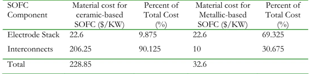
(32) Though SOFCs operating at temperatures above 750°C are currently performing better, they also cost almost 8 times more than those operating below that temperature. Current the reason for this is the cost of ceramic interconnects that can withstand those operating temperatures. At over $200 per kW, ceramic interconnect materials alone account for 90 % of the total material costs for high temperature SOFCs. Lowering the operating temperature into a range where metallic interconnects can be used reduces the interconnect materials cost by 200 % to $10 per KW. Table 4 shows a comparison of the relative cost per KW for SOFCs using metallic or ceramic interconnect materials [78]. SOFC Component Electrode Stack. Material cost for ceramic-based SOFC ($/KW) 22.6. Percent of Total Cost (%) 9.875. Material cost for Metallic-based SOFC ($/KW) 22.6. Percent of Total Cost (%) 69.325. Interconnects. 206.25. 90.125. 10. 30.675. Total. 228.85. 32.6. Table 4. Relative cost per kW of SOFC materials in a stack with metallic-based interconnects and with ceramic-based interconnects.. The interconnect composition used for SOFC is dependent on the application and temperature range. The composition determines the physical properties of the alloy and further the temperature range at which the thermal properties mirror those of the electrolyte. The materials used for interconnects involve nickel and often chromium forming ferriticbased alloys which ensure sufficiently high conductivity for thin oxide scales. With respect to thermal expansion, electrical conductivity and corrosion behaviour, the Cr Fe5 Y2O3 ODS alloy developed by Plansee in cooperation with Siemens shows excellent behaviour at temperatures up to 950 °C [79]. A disadvantage of the alloy produced by powder metallurgy is the currently high price which could be drastically reduced by suitable production techniques. From the aspect of costs, ferritic chromium steels are attractive candidates for metallic bipolar plates. On the one hand, they form chromium oxides, have a lower thermal expansion compared to austenitic alloys and can be mechanically easily deformed and machined.. N.Q. Minh and T .Takahashi, Science and Technology of Ceramic Fuel Cells. Elsevier Science B.V., Amsterdam, The Netherlands, 1995. 79 W. Thierfelder, H. Greiner, W. Ko¨ck, in: U. Stimming, S.C. Singhal, H. Tagawa, W. Lehnert (Eds.), Proc. 5th Int. Symp. Solid Oxide Fuel Cells (SOFC-V), The Electrochemical Society, Pennington, NJ, 1997, p. 1306. 78. 32.
Figura
+7


Documenti correlati
Chiaramente un abbassamento della temperatura di esercizio da 900-1000 °C delle celle attuali a 600 °C delle SOFC in fase di studio comporta una serie di vantaggi,
We derive upper limits on the annihilation cross section hσvi for monoenergetic DM lines at the level of 4 × 10 −28 cm 3 s −1 at 1 TeV, assuming an Einasto DM profile for the Milky
Type of ecclesiastical architecture World Heritage sites in the country Byzantine monasteries, Armenian ecclesiastical architecture 3 3 Armenia 1 11 Cathedral pre-Gothic style Belgium
Nel caso di questa eventualità, cercheremo di identificare anche quali caratteristiche corporee, quali atteggiamenti e quali espressioni volle porre in evidenza (per esempio,
Henry Frendo, Giuseppe Giliberti, Anna Maria Giomaro, Guido Guidi, Giulio Illuminati, Andrea Lovato, Luigi Mari, Remo Martini, Lucio Monaco, Vittorio Parlato, Paolo
I test effettuati sulle celle simmetriche e sulle celle complete a seguito del trattamento redox in situ hanno dimostrato che per tutte le composizioni si ottiene un incremento
Figura 9 Valore dell’efficienza termodinamica in funzione della temperatura di funzionamento dello stack per diversi combustibili [Font: “Solid Oxide Fuel
The results of the numerical study show that a priori information, either from laboratory data or from information at the regional scale, fail in accurately
