M
ASTER
T
HESIS
Adaptive and robust leg control of a
hexapod robot for space exploration
Author:
Roberto Travaglini
Matr. 816775
Supervisor:
Mauro Massari
Degree of Space engineering
Dipartimento di Scienze e Tecnologie Aerospaziali
Scuola di Ingegneria Industriale e dell’Informazione
Abstract
Dipartimento di Scienze e Tecnologie Aerospaziali Scuola di Ingegneria Industriale e dell’Informazione
Space engineering
Adaptive and robust leg control of a hexapod robot for space exploration
by Roberto Travaglini
Legged robots have shown incredible capabilities to operate on difficult ter-rains. This characteristic could be very useful for space exploration, but in this environment all the systems have to be very reliable and robust. The greatest challenge is to control the high number of degrees of freedom of the legs. To build a versatile and robust control system, it is crucial to have a single leg con-troller that is adaptive and versatile. The designed system has to be able to change the frequency and the length of its steps according to some controlling inputs. To accomplish this task using a low computational power and at the same time maintaining a high robustness, the design of the control system is bi-ologically inspired from studies on the behavior of stick insects. This approach leads to the development of a dynamic artificial neural network. After a train-ing phase, this system is able to obtain a walk with all the required behaviors. In addition, even though it receives data from the sensors to adjust its behavior to the external environment, it is not strictly dependent on these feedbacks, and it can even work in case of sensors failures. At the end, the obtained system is a simple pre-trained network that can activilely adapt its behavior, while being highly robust. Thanks to these qualities, this controller could be the optimal basis to build a complete control system for a hexapod robot in future works.
Key words: neural network, walking robot, biomimicry, adaptive control.
Abstract iii
1 Introduction 1
1.1 Walking system . . . 1
1.2 State of the art . . . 2
1.2.1 Walknet . . . 2 1.2.2 AMOS II . . . 2 1.2.3 LAURON V . . . 3 1.2.4 COMET IV . . . 4 1.2.5 NEMeSys . . . 4 1.3 Biomimicry . . . 4 1.4 Thesis contribution . . . 5
2 Artificial neural networks 7 2.1 Structure . . . 7
2.2 Static and dynamic neural networks . . . 8
2.2.1 Static networks . . . 8 2.2.2 Dynamic networks . . . 9 2.2.3 CTRNN . . . 9 2.2.4 Two-neuron CTRNN . . . 10 ANN 1 . . . 10 ANN 2a . . . 11 ANN 3 . . . 12
2.2.5 Frequency of the limit cycles . . . 13
2.3 Genetic algorithm . . . 15
2.4 Training of a two-neuron CTRNN . . . 16
3 Simulation model 21 3.1 Hexapod configuration . . . 21
3.2 Model design in the simulation environment . . . 23
3.3 Control model . . . 23
3.4 Ground contact . . . 24
3.5 Simplified simulation model . . . 25
4 Training of the single leg 27 4.1 Artificial neural network . . . 27
4.2 Neuron model . . . 28
4.2.1 CPG layer . . . 28
4.2.2 Outer layer . . . 29
4.2.3 Static layer . . . 29 v
Level 2 . . . 31
Level 3 . . . 31
Level 4 . . . 31
4.4 Results . . . 32
5 Adaptive control for the single leg 41 5.1 Variable step length . . . 41
5.1.1 Neural network . . . 41
5.1.2 Fitness function . . . 43
5.1.3 Training on the simplified model . . . 45
Results . . . 45
5.1.4 Training with the full model . . . 49
5.1.5 Target step variation during the simulation . . . 53
5.2 Variable step length and frequency . . . 55
5.2.1 Frequency change . . . 55
5.2.2 Final system . . . 58
5.2.3 Target frequency variation during the simulation . . . 60
6 Robustness analysis 63 6.1 Rough terrain . . . 63
6.1.1 Simulations . . . 64
6.2 Inclined terrain . . . 67
6.2.1 Horizontal main body . . . 67
6.2.2 Inclined main body . . . 70
6.3 Noise on the sensors . . . 73
6.4 Failure of the sensors . . . 77
6.4.1 Body-coxa joint
γ
. . . 776.4.2 Coxa-femur joint
β
. . . 796.4.3 Femur-tibia joint
α
. . . 806.4.4 All joints . . . 81
6.5 All sensor failures on a rough terrain . . . 83
7 Conclusions 85 7.1 Results . . . 85
7.2 Future developments . . . 86
A Fixed step length ANNs 87 B Variable step length ANNs 89
1.1 Tarry hexapod. . . 2
1.2 AMOS II hexapod. . . 3
1.3 LAURON V hexapod. . . 3
1.4 COMET IV hexapod. . . 4
1.5 The stick insect Carausius morosus. . . 5
2.1 Neural network. . . 8
2.2 Recurrent neural network . . . 9
2.3 Phase diagram of ANN 1. . . 11
2.4 Phase diagram of ANN 2a. . . 11
2.5 Phase diagram of ANN 3. . . 12
2.6 Frequency spectrum diagram of
y
1of ANN 2a (τ
1=τ
2=1). . . 132.7 Frequency spectrum diagram of
y
1of ANN 2b (τ
1=τ
2=0.5). . . . 132.8 Frequency spectrum diagram of
y
1of ANN 2c (τ
1=τ
2=0.25). . . . 142.9 Phase diagram of
y
1 of the three ANNs. . . 142.10 Convergence of the genetic algorithm for the 2 neuron ANN. . . 17
2.11
y
1 frequency response of the obtained CTRNN . . . 172.12 Phase diagram of the obtained CTRNN . . . 18
2.13 Variation of the frequency of the limit cycle as a function of
k
τ that multiplies both the time constants . . . 192.14 Phase diagram of the obtained CTRNN . . . 20
3.1 The NEMeSys robot in a simulated martian environment. . . 21
3.2 Sketch of the leg configuration. . . 22
3.3 Scheme of the leg simulation model. . . 23
3.4 Scheme of the control model of the single leg. . . 24
4.1 Architecture of the ANN. . . 28
4.2 Genetic algorithm convergence for the fixed step length and fixed frequency leg control ANN. . . 32
4.3 Distance traveled by the leg. . . 33
4.4 Lengths of the steps on the time-line. . . 34
4.5 Height of the foot of the leg. . . 34
4.6 Projection of the foot in the y-z plane after the transient of 10 seconds. . . 35
4.7 Frequency content of the angular position
γ
. . . 354.8 Target and real angular position
γ
. . . 364.9 Target and real angular position
β
. . . 364.10 Target and real angular position
α
. . . 374.11 Height of the foot of the leg (2ndtraining). . . 37
4.13 Lengths of the steps on the time-line (3rdtraining). . . 39 4.14 Frequency content of the angular position
γ
(3rdtraining). . . 39 5.1 Architecture of the ANN that can produce a variable step length. 42 5.2 Convergence of the genetic algorithm for the variable steptrain-ing on the simplified model. . . 46 5.3 Comparison of the length of each step for the variable step ANN
with 12 cm and 18 cm as target step length inputs. . . 47 5.4 Comparison of the angular position
γ
for the variable step ANNwith 12 cm and 18 cm as target step length inputs. . . 47 5.5 Comparison of the foot projection on the y-z plane, after the
tran-sient (20 seconds), for the variable step ANN with 12 cm and 18 cm as target step length inputs. . . 48 5.6 Comparison of the angular position
β
for the variable step ANNwith 12 cm and 18 cm as target step length inputs. . . 48 5.7 Comparison of the angular position
α
for the variable step ANNwith 12 cm and 18 cm as target step length inputs. . . 49 5.8 Step length as function of time obtained using the ANN found in
section 5.1.3 with 12 cm and 16 cm as target step lengths. . . 50 5.9 Projection of the foot position in a reference frame moving with
the main body obtained using the ANN found in section 5.1.3 with 12 cm and 16 cm as target step lengths. . . 50 5.10 Step length as function of time obtained using the ANN resulting
from the GA with 12 cm and 17 cm as target step lengths. . . 51 5.11 Projection of the foot position in a reference frame moving with
the main body obtained using the ANN resulting from the GA with 12 cm and 17 cm as target step lengths. . . 52 5.12 Foot elevation as function of time obtained using the ANN
re-sulting from the GA with 12 cm and 17 cm as target step lengths. 52 5.13 Foot elevation as function of time obtained using the ANN
re-sulting from the GA with 12 cm as target step length for a time length of 300 seconds. . . 53 5.14 Step length as function of time for a simulation that changes the
target step from 12 cm to 15 cm. . . 54 5.15 Angular position
γ
as function of time for a simulation that changesthe target step from 12 cm to 15 cm. . . 54 5.16 Projection of the foot position in a reference frame moving with
the main body for a simulation that changes the target step from 12 cm to 15 cm. . . 55 5.17 Step length as function of time for two simulations respectively
at 0.4 Hz and 0.5 Hz. . . 56 5.18 Projection of the foot position in a reference frame moving with
the main body for two simulations respectively at 0.4 Hz and 0.5 Hz. . . 56
and target step length . . . 58 5.21 Step length as function of time for two simulations respectively
at 0.4 Hz and 0.5 Hz (also using the interpolating function). . . . 59 5.22 Projection of the foot position in a reference frame moving with
the main body for two simulations respectively at 0.4 Hz and 0.5 Hz (also using the interpolating function). . . 59 5.23 frequency content of
γ
and the foot elevation for two simulationsrespectively at 0.4 Hz and 0.5 Hz (also using the interpolating function). . . 60 5.24 Step length as function of time for a simulation that changes
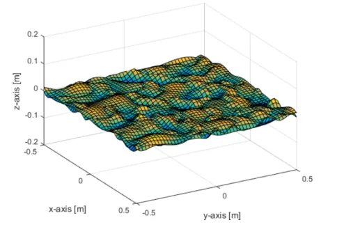
fre-quencies from 0.4 Hz to 0.5 Hz. . . 60 6.1 Terrain model. . . 64 6.2 Projection of the foot in the y-z plane for a simulation on a rough
terrain (case 1). The black line is the ground profile. . . 65 6.3 Step length for a simulation on a rough terrain (case 1). . . 65 6.4 Projection of the foot in the y-z plane for a simulation on a rough
terrain (case 2). The black line is the ground profile. . . 66 6.5 Step length for a simulation on a rough terrain (case 2). . . 67 6.6 Projection of the foot in the y-z plane for a simulation on a terrain
with a slope of 20o. The black line is the ground profile. . . 68 6.7 Step length for a simulation on a terrain with a slope of 20o. . . . 68 6.8 Projection of the foot in the y-z plane for a simulation on a terrain
with a slope of -20o. The black line is the ground profile. . . 69 6.9 Step length for a simulation on a terrain with a slope of -20o. . . . 70 6.10 Step length for a simulation on a terrain with a slope of 25o. . . . 70 6.11 Projection of the foot in the y-z plane for a simulation on a terrain
with a slope of 25o. The black line is the ground profile. . . 71 6.12 Projection of the foot in the y-z plane for a simulation on a terrain
with a slope of -30o. The black line is the ground profile. . . 72 6.13 Step length for a simulation on a terrain with a slope of -30o. . . . 72 6.14 Error on the measurement of
γ
caused by the noise. . . 73 6.15 Comparison between the angular positionγ
read by the sensorand the real one. . . 74 6.16 Comparison between the angular position
β
read by the sensorand the real one. . . 74 6.17 Comparison between the angular position
α
read by the sensorand the real one. . . 75 6.18 Enlargement of figurefig:betano . . . 75 6.19 Step length for a simulation with sensors affected by noise. . . . 76 6.20 Projection of the foot position in a reference frame moving with
the main body for a simulation with sensors affected by noise . . 76 6.21 Step length for a simulation with the
γ
sensor off. . . 77 6.22 Projection of the foot position in a reference frame moving withthe main body for a simulation with the
γ
sensor off. . . 78 ix6.25 Step length for a simulation with the
γ
sensor off. . . 79 6.26 Projection of the foot position in a reference frame moving withthe main body for a simulation with the
γ
sensor off. . . 80 6.27 Step length for a simulation with theγ
sensor off. . . 81 6.28 Projection of the foot position in a reference frame moving withthe main body for a simulation with the
γ
sensor off. . . 81 6.29 Step length for a simulation with all the sensors off. . . 82 6.30 Projection of the foot position in a reference frame moving withthe main body for a simulation with all sensors off. . . 82 6.31 Projection of the foot position in a reference frame moving with
the main body for a simulation on a rough ground with all the sensors off. . . 83 6.32 Step length for a simulation on a rough ground with all the
sen-sors off. . . 84
2.1 Parameters of the two neuron CTRNNs. . . 12 2.2 Parameters of the two neuron CTRNNs obtained through the GA. 19 3.1 The PID controller for the joints. . . 24 3.2 Angular limits for the three joints. . . 24 5.1 Input frequency and input step length obtained from the
inter-polating function. . . 58 A.1 Parameters of the CTRNN obtained through the GA in section 4.4. 87 B.1 Parameters of the CTRNN obtained through the GA in chapter 5. 89
ANN Artificial Neural Network
CPG Central Pattern Generator
DOF Degree Of Freedom
CTRNN Continuous Time Recurrent Neural Network
GA Genetic Algorithm
PID Proportional–Integral–Derivative
Introduction
The aim of this thesis is to improve the understanding of the capabilities of legged robots through the design of a biologically inspired control system for the leg of a hexapod robot. The goal is to have a versatile and adaptive but simple control system for the single leg, that could be the basis for the design of a flexible and robust control system for the whole robot, once implemented with a coordinating unit.
1.1
Walking system
In the history of space exploration, few rovers have been employed for in-situ exploration of Mars and of our Moon, but all of them used wheels to propel themselves on the ground. The reason is that wheeled systems are simpler devices, easier to program and move faster than legged systems. The potential advantages of a walking system are:
• Legs operate better on rough terrains, they don’t need a relative smooth terrain as wheels. They can avoid holes and surmount obstacles and pro-ceed on terrains steeper with respect to the wheeled rovers.
• Having many controllable degrees of freedom, the system is more versa-tile and adaptable. Wheeled systems can just control direction and angu-lar velocity of the wheels, therefore many trajectories corrections may be needed to explore the whole space, whereas a legged system with their level of complexity can turn and follow any trajectory, directly reaching any point in the space.
• The attitude of the main body can be controlled independently from the terrain configuration.
• It can distribute its weight and move its center of mass without changing the points of contact on the ground.
For these reasons, there has been a growing interest in the development of walking systems for space exploration.
1.2
State of the art
This section will provide an overview of the most advanced hexapod walking systems. The first four systems were chosen because they are all biologically inspired approaches and they used different methods to solve the control prob-lem of six-legged robots. The last robot is the model used in this thesis.
1.2.1
Walknet
Walknet [10] is an hexapod controller developed at the University of Bielefeld. It is inspired by the walking behavior of stick insects. It implements a decen-tralized artificial neural network (ANN) that operates dividing the walking be-tween two phases: a stance phase and a swing phase. The transition is regu-lated by two parameters: the ground contact and the posterior extreme posi-tion. The control system implements the feedback of the joint sensors that is necessary for the switching unit. Walknet has been successfully implemented on two robots: TUM built at the Technische Universität München [12] and the Tarry family built at the University of Duisberg [11].
FIGURE1.1: Tarry hexapod.
1.2.2
AMOS II
AMOS II is a biologically inspired hexapod platform that has a control system based on an ANN that focused its attention on obstacle negotiation behavior and having variable walking gaits [13]. The control system is composed by three major parts: adaptive backbone joint control, central pattern generator (CPG) and local leg reflex control. Apart from the usual joint sensors, it exploits ultrasonic sensors at the front of the robot to detect obstacles and it uses this data as an input for the control system.
FIGURE1.2: AMOS II hexapod.
1.2.3
LAURON V
LAURON is a family of hexapods being developed at the Forschungszentrum Informatik Karlsruhe (FZI) in Germany since 1994. The last model LAURON V [8] was finished in 2013. The robot is intended to be used in rough and humans hazardous areas for inspection and maintenance tasks. It also has the ability to manipulate objects with its front legs. It can cope with difficult and rough ter-rain thanks to the behavior-based control system, that controls the four DOFs of each leg. Behavior-based systems are reactive systems, which means they exploit the input received from the different sensors to correct their actions ac-cording to the surrounding environment.
1.2.4
COMET IV
COMET IV is a hydraulically actuated six-legged robot developed at Chiba University by a team lead by professor K. Nonami that aims at actual mine detection and removal. It has an impedance control system, subdivided in the single-leg and the center of mass-based parts, that allows it to walk in uneven and extremely soft terrains [5]. This type of control systems focuses on modu-lating and regumodu-lating, not the robot’s motion or the force it exerts, but rather its impedance output [4].
FIGURE1.4: COMET IV hexapod.
1.2.5
NEMeSys
NEMeSys is a six-legged robot being developed at Politecnico di Milano. It will be the model used for this thesis and a detailed description of the hexapod can be found in chapter 3. It is used as a platform to test innovative control systems. The control of the single leg [9] used until now is composed by two different ANNs, a swing module and a stance module. So it needs a selector that switches between the two, depending on the leg position that is derived using data from the contact and joint sensors.
1.3
Biomimicry
Biomimicry or biomimetic is the emulation of nature’s systems , models and/or strategies for the purpose of solving human problems. During this thesis, stud-ies on the behavior of the stick insects Carausius morosus [1] were analyzed to design a control system for hexapod walking robots. It is one of the most stud-ied insect for the design of hexapod systems, because its morphology has all the
legs and joints well visible. It solves the complex problem of coordinating all the DOFs performing a very effective walk that can variate speed, trajectories on any kind of terrain.
FIGURE1.5: The stick insect Carausius morosus.
The first important question is whether there is a common pattern genera-tor for all the legs or each leg has its own system that is partially independent from the others. By means of amputation experiments and studies where one of the legs was constrained to move on a motor driven surface, it has been found out that each leg has its own CPG (central pattern generator) and there are coordinating pathways between them that allow the animal to walk. The walking-pattern of each leg is characterized by a stance and a swing phase and the transition is performed considering sensory feedbacks coming from the sense organs measuring position, by sense organs measuring load and by coordinating influences from other legs. It has been studied that the system is very robust to external disturbances, errors from sensor organs and even to leg amputations.
1.4
Thesis contribution
The studies on the stick insect have shown that each leg has its own pattern generator and is partially independent from the others. Therefore the objective of this thesis is to develop a single-leg control system by means of an ANN that shows the same versatility of the counterpart in nature. This means developing a system that has a variable step length and can operate at different frequencies depending on the inputs. The difference from the control system already de-veloped [9] for the single leg is that the goal is to obtain all the characteristics
using a single ANN. The reason is to have a simple control system that will re-quire less computational power and therefore be more suitable and reliable for space exploration. Moreover all the systems presented in the state of the art rely totally on the correct functioning of the sensors, especially the one that detects the contact with the ground. So one of the objective is to develop a system that doesn’t need the contact feedback and that is robust to sensor errors.
At the beginning this thesis will analyze the range of possibilities of ANNs (chapter 2), understanding their behavior in simple networks, and it will study the potentiality of genetic algorithms to find the best parameters of each neu-ron. Chapter 3 will describe the model used for the simulations. The trainings of the single leg is analyzed in chapter 4, where the ANN architecture is shown and the problem of walking with a fixed step length and frequency is solved. Chapter 5 introduces the possibility of changing in real time the length and the frequency of the step as function of the input desired frequency and step length. Finally chapter 6 will perform a sensitivity analysis on the obtained control system showing the robustness with respect to system errors and com-plex environments. The aim of this thesis is to design a versatile control of a single leg that can change its behavior modifying a defined set of controlling inputs. This simple ANN could be later implemented with a coordination unit to obtain a robust control system for the whole hexapod that would allow dif-ferent walking speeds and curved trajectories.
Artificial neural networks
It is known that the brain of the animals can perform certain computation much faster then the most advanced computers. The stick insects are able to solve the complex problem of walking through simple biologic neural networks(section 1.3). Therefore biologically inspired models called artificial neural network (ANN) were developed. They can be used to estimate complex unknown func-tions, but also as control systems. Before using it to develop the leg controller, it is necessary to deeply understand the behavior of these systems and how they can be trained to perform in the desired way.
The advantages of these systems are:
• they can manage a great amount of data with great accuracy; • they are robust to noise, errors and even failure of inputs;
• the principle of non-linear, distributed, parallel and local processing and adaptation allows them to outperform classical algorithms;
• they can be implemented on a parallel hardware greatly optimizing their computational efficiency;
The peculiarity of an ANN is that it can learn from experience. The neural network has to perform a training that will tune the neural parameters and weights, allowing the system to solve a complex problem that would have been much harder to solve using ordinary programming. The disadvantage of these systems is that they often can’t be explained analytically and will have to be treated like black boxes.
2.1
Structure
An ANN is constituted by nodes, called artificial neurons, which exchange in-formation between all or part of each other through connections called synapses. Each neurons is characterized by:
• an output
y
i;• an activation function
σ
; • an activation biasθ
i;• an external input
I
iEach synapse that sends the signal from neuron
i
to neuronj
is characterized by a weightw
ij.2.2
Static and dynamic neural networks
Neural networks can be divided in two groups: static and dynamic.
2.2.1
Static networks
Static networks are reactive agents, this means that they will produce a specific output that depends only on the inputs at the current instant. Starting from the sample data, the correct set of parameters can be calculated through a training process. These systems will be able to solve complex problems and it can be very useful dealing with a high number of inputs. A typical neuron can be represented as:
y
i=
NX
j=1w
ijσ(y
j+ θ
j) + I
i (2.1)where
y
i are the neuron outputs,w
ij are the synaptic weights,θ
j are theacti-vation bias,
σ
is the activation function andI
i are the external inputs.FIGURE2.1: Neural network.
A typical representation of a neural network is shown in figure 2.1 where the neurons subdivided in layers and the synapses can be identified. The layers of ANNs can be divided in three categories:
• an input layer;
• an output layer.
Simple neural networks can have just the input and the output layers, without any hidden layer.
2.2.2
Dynamic networks
In biological neural network signal delays are omnipresent and play an im-portant role in neurobiological information processing. Dynamic neural net-works can manifest time dependent behaviors such as transient phenomena and time delays. Moreover they offer better computational capabilities com-pared to their static counterpart [3]. Simple nervous system can be used as autonomous agents because they can initiate actions independently from their immediate situation, and they can also organize their behavior in anticipation of future events. Static networks are all feed forward neural network, informa-tion flows in a single direcinforma-tion. Dynamic neural networks usually employ ex-tensive feedback between neurons of the same layer, and/or between different layers. Networks with at least one feedback loop can be identified as recurrent neural networks.
FIGURE2.2: Recurrent neural network
The equation of the nodes are differential equations that can be generally represented as:
˙
y
i= f (τ
i, w
ij, y
j, θ
i, I
i)
j = 1, ..., N
(2.2)where f is the generic function that combines all the inputs, and
τ
i is the timeconstant of the single neuron.
2.2.3
CTRNN
The continuous time recurrent neural network (CTRNN)[2] is the chosen type of neural network in this work because:
• it is arguably the simplest nonlinear, continuous dynamical network model; • it is a universal dynamic approximator: they can approximate the
trajec-tories of any smooth dynamical system arbitrary well. Neurons of CTRNNs follow the general form:
˙
y
i=
1
τ
i−y
i+
NX
j=1w
jiσ(y
j+ θ
j) + I
i!
(2.3)σ
is the activation function and the most used are: •σ(x) = 1/(1 + e
−x)
;•
σ(x) = tanh(x)
.CTRNNs show some typical nonlinear behaviors such as: • multiple local equilibrium points;
• bifurcations, where small changes in the parameters can causes sudden changes in the network behavior;
• limit cycles.
Limit cycles are closed trajectories in the phase space and this periodic dynamic is fundamental to generate the pattern needed for the control of the leg. This behavior can already be seen in two-neuron circuits.
2.2.4
Two-neuron CTRNN
Two-neuron CTRNNs are represented by a system of two equations:
˙
y
1=
1
τ
1(−y
1+ I
1+ w
11σ(y
1+ θ
1) + w
21σ(y
2+ θ
2))
˙
y
2=
1
τ
2(−y
2+ I
2+ w
12σ(y
1+ θ
1) + w
22σ(y
2+ θ
2))
(2.4)
where the chosen activation function is
σ(x) = 1/(1+e
−x)
. Changing the pa-rameters, two-neuron circuits can have all the behaviors listed in section 2.2.3, as shown in the following examples. Table 2.1 lists all the parameters of the chosen neural networks [2]. In these examples, different initial conditions were chosen in order to show all the possible behaviors of the CTRNNs.ANN 1
FIGURE2.3: Phase diagram of ANN 1.
ANN 2a
It has a limit cycle and the system will converge to it whatever the initial con-ditions are.
ANN 3
This is a much more complex solution. In this plot it is possible to identify: • a limit cycle (
y
1= 6.11, y
2= 4.05
);• an equilibrium point (
y
1= 5.32, y
2= 1.45
);• a saddle point (
y
1= 4.3, y
2= 0.5
).Whether the system converges to the limit cycle or to the equilibrium point, it depends on the initial condition. This example explains that in CTRNNs, even a small perturbation in the initial conditions can produce very different behaviors.
FIGURE2.5: Phase diagram of ANN 3.
TABLE2.1: Parameters of the two neuron CTRNNs.
ANN
w
11w
12w
21w
22θ
1θ
2I
1I
2τ
1τ
2 1 3 -1 1 3 -2 -1 0 0 1 1 2a 4.5 -1 1 4.5 -2.75 -1.75 0 0 1 1 3 5.5 -1 1 5.5 -3.233 -1.75 0 0 1 1 2b 4.5 -1 1 4.5 -2.75 -1.75 0 0 0.5 0.5 2c 4.5 -1 1 4.5 -2.75 -1.75 0 0 0.25 0.252.2.5
Frequency of the limit cycles
In this work the most interesting behavior is the limit cycle, because it will allow the system to walk. The examples in section 2.2.4 have shown how it is possible to have different limit cycles, but it has not provided any data on the frequency content. To analyze this aspect, the ANN 2a was taken as model and the time constants were changed. As it can be seen from table 2.1, the time constants of the two neurons of the same ANN are equal. Then they were divided by 2 and 4 respectively for ANN 2b and ANN 2c. The results can be seen in figures 2.6, 2.7 and 2.8.
FIGURE 2.6: Frequency spectrum diagram of y1 of ANN 2a
(τ1=τ2=1).
FIGURE 2.7: Frequency spectrum diagram of y1 of ANN 2b
(τ1=τ2=0.5).
The resulting frequencies of the cycles are: •
f
2a= 0.14
Hz;•
f
2b= 0.275
Hz;•
f
2c= 0.55
Hz.FIGURE 2.8: Frequency spectrum diagram of y1 of ANN 2c
(τ1=τ2=0.25).
It is clear that dividing the time constant by a value corresponds to multi-plying the oscillation frequency for the same value. The small error is due to the fact that the frequency domain obtained through the simulation is discrete.
The next point is to see how the limit cycle changes apart from the frequency. Figure 2.9 shows that the limit cycles are exactly the same on the phase diagram. So multiplying the time constants for a same value produces variations only in the frequency content of the states. For the sake of clarity, the initial conditions are slightly different for the three ANNs otherwise, if they were the same, the trajectories would have overlapped exactly.
2.3
Genetic algorithm
As previously said, ANNs need to go through a training to find the correct pa-rameters to obtain the desired behavior. The general process consists in chang-ing the network parameters and compare the outputs with the desired ones. In this work, we don’t have desired output, the movement of the leg, but we have objectives such as the step length or the frequencies, therefore the goodness of the network will be evaluated through specific fitness functions. The fitness function provides a scalar value, that depends on selected simulation outputs. A low value of the fitness function means a good behavior of the ANN, whereas a high value means a ineffective ANN. The chosen training process is inspired by nature as it is based on the evolutionary approach. It uses a genetic algo-rithm (GA). This system was chosen because:
• they perform well in nonlinear environment; • they can manage a high number of variables; • they can explore well all the space of solutions;
• they can perform faster exploiting parallel computing.
ANNs are seen as members of a population that evolves and the best ones (se-lected looking at the fitness function) will reproduce, transferring part of its genes (parameter values) to the following generation. The following genera-tion is composed by:
• sons, they inherited genes from one or more parents from the previous generation and they are also subjected to random mutations;
• a set number of the best individuals that survives from the previous gen-eration.
In particular, the first generation is created randomly. Then a simulation is run for each individual with the evaluation of the fitness function and the best ones will reproduce to create the next generation. This process will repeat itself until the requirements on the fitness function are satisfied.
The genetic algorithm has many parameters to be chosen such as the pop-ulation size, the percentage of parents kept in every generation, the maximum number of generations. The most important part is to find a good fitness func-tion. Finally the genetic algorithm can be started and it will continue until one of the following stopping criteria is reached:
• the objective fitness function value is reached; • the number of maximum generation is reached;
• the fitness function value has not improved for a set number of genera-tions.
If the stopping criteria is different from the first one, it means that the desired behavior was not reached and therefore changes in the fitness function or the GA parameters may be necessary. But there is also the possibility that an ANN with that kind of architecture can’t have the desired behavior, thus it will have to be modified.
2.4
Training of a two-neuron CTRNN
To understand the potentiality of the CTRNN trained with a GA, a study on the two-neuron circuit was performed. The chosen objective is to obtain a desired oscillation range at the desired frequency for the two neural states. To under-stand the behavior of the GA and the versatility of the ANN it can be interesting to evaluate:
• the convergence speed of the algorithm;
• the possibility of finding networks in different parts of the parameters space that satisfy the requirements.
The neuron equation is represented by equation 2.4, but a different activa-tion funcactiva-tion was chosen (
σ(x) = tanh(x)
) because with it, the system is more likely to have limit cycles[6]. Actually tests using the logistic function were tried at first, but the GA did not converge to any good solution. The ex-ternal inputsI
iwere all set to 0.First of all the fitness function checks if a limit cycle is present. If it is present, the actual fitness function can be evaluated and its equation is:
f
f=
2X
i=1
A(y
i(f )) + B(y
i(f )) + C(y
i(t))
(2.5)where the
A(y
i(f )), B(y
i(f ))andC(y
i(t))
are function of the states infre-quency or time domain and they are respectively: A) the amplitude of the oscillation;
B) the sharpness of the peak on the frequency spectrum; C) the mean value of the oscillation.
and they are represented by the following equations:
A(y
i(f )) = ||y
imax(f )| −
amp
target2
|
B(y
i(f )) =
|y
mean i(f )|
|y
max i(f )|
C(y
i(t)) = |y
imean(t) − mean
target|
(2.6)
The target mean value (
mean
target) and amplitude of the oscillation(amp
target)of both the neural states are respectively 0 and 2. The maximum generation number was set to 100 and the convergence speed is shown in figure 2.10.
FIGURE2.10: Convergence of the genetic algorithm for the 2 neu-ron ANN.
The GA converges rapidly to a decent solution with the fitness function reaching a value of ~0.1 in about 50 generations. Then there are just small im-provements. At the end of the GA, the errors on the mean value and on the amplitude value are all less then 0.01.
FIGURE2.12: Phase diagram of the obtained CTRNN
The target frequency does not appear in the fitness function, because as it was said in section 2.2.5, it can be adjusted manually modifying the time con-stants. It is possible to include the target frequency in the fitness function, but this would slow down the convergence of the GA. The frequency response and the limit cycle are shown respectively in figures 2.11 and 2.12. The phase di-agram shows that after the transient, the two neural state follow a limit cycle and oscillate between -1 and 1. The frequency of the peak was the same for the two neurons and in this case it was 0.4883 Hz. It is important to keep in mind that in all these simulations, the frequency domain is discrete. It was shown in section 2.2.5 that the frequency of the peak can be changed dividing both the time constants for the same value,
k
τ (τ
new= τ
old/k
τ), without changingthe other characteristics of the limit cycle. This method worked also with this CTRNN and the relationship between
k
τ and the target frequency is shownFigure 2.13. In this way it is possible to change the frequency of the limit cycle found through the GA.
FIGURE 2.13: Variation of the frequency of the limit cycle as a
function of kτ that multiplies both the time constants
The GA was run a second time to see the eventual differences. The new so-lution had a different limit cycle that still fulfills the requirements and its limit cycle is shown in figure 2.14. The shape is caused by the fact that the two neu-rons have a different phase between each other with respect to the previous ANN. Table 2.2 shows the parameters obtained in the trainings. No similari-ties between the two solutions can be identified, and therefore it is possible to conclude that ANNs that have the desired behavior can be found in completely different areas of the space of the parameters.
TABLE 2.2: Parameters of the two neuron CTRNNs obtained through the GA.
w
11w
12w
21w
22θ
1θ
2τ
1τ
22.9236 7.6928 -14.9987 0.4084 -0.0151 -0.0206 0.9534 0.4836 4.2527 3.5615 -3.8987 -1.5250 -0.0247 -0.0343 0.8355 0.7861
FIGURE2.14: Phase diagram of the obtained CTRNN
This chapter has shown that ANN can produce autonomously limit cycles and that GAs are able to find CTRNNs with a desired behavior. It also found an easy way to change the frequency of oscillation of the neural states. The two-neuron circuits studied here are just examples, but it was important to fully un-derstand their capabilities before proceeding to more complex neural networks that may be used to control the leg of a hexapod.
Simulation model
The purpose of this chapter is to describe the model used in the different simu-lations. The first part gives an overview on the physical platform that is taken as reference for the simulation models and the second one deals with its repre-sentation in the simulation environment.
3.1
Hexapod configuration
FIGURE3.1: The NEMeSys robot in a simulated martian
environ-ment.
The simulation model is taken from NEMeSys, that stands for Neural Ento-Mechanic System, and it refers to a hexapod robot developed by the department of Aerospace Science and Technology of Politecnico di Milano. It was designed to be used as a platform to test innovative control systems. The robot is com-posed by a main body with a parallelepiped shape that stores the electronic
boards. Its dimensions are: a length of 600 mm, a width of 193 mm and a thick-ness of 32 mm. Each of the six legs is composed by three segment that have each a relative rotational degree of freedom with respect to the previous one.
Starting from the main body we can identify:
• the body-coxa joint that enables a rotation
γ
around the z-axis; • the coxa that is 53 mm long;• the coxa-femur joint that enables the rotation
β
around the y-axis; • the femur that is 126 mm long;• the femur-tibia joint that enables the rotation
α
around the y-axis; • the last segment, the tibia that is 200 mm long;• the foot that the tip of the tibia and it is the part that actually comes in contact with the ground.
FIGURE3.2: Sketch of the leg configuration.
The three rotational degrees of freedom are defined in the following way: •
γ
angle that is positive when the leg moves forward;•
β
angle that is positive when the knee moves upward; •α
angle that is positive when the leg extends.The configuration can be clarified by looking at figure 3.2. The movements of the three joints can be defined as:
• protraction and retraction, respectively a positive and negative variation of
• levation and depression, respectively a positive and negative variation of
β
; • extension and flession, respectively a positive and negative variation ofα
; Each joint is equipped with an angular position sensor that will be used as a feedback for the network. The joints are actuated by electric motors.3.2
Model design in the simulation environment
This work is focused on the control of the single leg and therefore only the leg will be modeled for the simulations.
FIGURE3.3: Scheme of the leg simulation model.
The model is represented as a multi-body system where the bodies are con-nected to each other by joints. Each body is considered perfectly rigid and it is defined by the initial position of notable points. The leg is represented as three separate axes, each one defined by its extremities and its center of mass. The joints are represented as revolute primitive joints that enable the relative rotational degree of freedom between two parts. The main body is represented by a prismatic primitive joint that allows the body-coxa joint to translate hor-izontally in the direction of travel. This choice was made because the thesis is focused on the behavior of the single leg. The translational movement will be allowed only when the leg touches the ground and the main body will re-main still when it’s detached. This will not be the real behavior when the leg control will be implemented on the whole hexapod, but it is necessary, because otherwise, the main body will move due to its own inertia and it would not be possible to study the behavior of the single leg.
3.3
Control model
The control of the system will be performed using an ANN that will be devel-oped in chapters 4 and 5. The output of the ANN will be the target angular position of the joints,
u
t. A PID controller for each joints is used to providethe required torque,
T
t, to the actuators. The coefficients of the PID controllerwhere obtained starting from the results obtained from the PID controller tuner in Simulink R and they can be seen in table 3.1. The goal was to have a fast controller, in the order of tenth of second that had a robust transient. A scheme of the whole system is shown in figure 3.4.
FIGURE3.4: Scheme of the control model of the single leg. TABLE3.1: The PID controller for the joints.
Proportional gain Integral gain Derivative gain Filter coefficient
10 50 30 100
Each of the three joints in the model will have an input torque,
T
a, and anactual angular position,
u
a. Then their sensors will feed the angular positions,u
s, back to the ANN. It is important to understand that while the leg touchesthe ground, the target angular displacemenst, output of the network, and the real angular displacements can be quite different due to the contact interaction. Moreover, it was considered that each joints has maximum and minimum an-gular positions that are shown in table 3.2.
TABLE3.2: Angular limits for the three joints.
γ
[deg]β
[deg]α
[deg] max 38 30 50min -38 -30 -50
3.4
Ground contact
For walking systems, the ground is a complex interaction to be modeled. In wheeled systems the contact with the surface is continuous but in legged sys-tem the foot keeps touching and detaching from the ground. This often produce the problem of zero-crossings that greatly slows or even stops the simulations. The zero-crossing happens when there is a switch, on or off, that is the contact in this case, and the simulation get stuck oscillating between the two states. Moreover for this work it’s important to have a good ground contact model, without any bouncing as this is the actual situation for the real model.
The ground contact has been characterized with both vertical reaction and friction. The ground reaction is represented as a spring-damper system that is activated when the relative vertical position of the foot is negative with respect
to the ground and it is represented by the following equation:
F
z= −k
p(sl
z− ¯
sl
z) − k
dvl
z (3.1)where
F
zis the reaction force,k
pis the proportional coefficient (=100000 N/m),k
dis the damping coefficient (=1000 N s/m),sl
zis the leg tip vertical position,vl
z is its vertical velocity whilesl
¯
z represents the penetrating dept of 1 mmwithout any elastic effect. Two saturation blocks, one right after the propor-tional part and one for the complete reaction force were used to guarantee the positivity of its module even when the leg is moving upwards (positive veloc-ity).
The friction is also modeled with a spring-damper system in order to emu-late the effects of a static friction. The friction has a maximum saturation pro-portional to the reaction force. The propro-portional and the damping coefficient are respectively 100000 N/m and 100 N s/m.
3.5
Simplified simulation model
Due to the high number of cycles performed during the GA training, a simple model was used at the beginning to quickly obtain preliminary results. The differences of this model are:
• the main body is considered fixed in space;
• the ground only gives a reaction force and no friction.
The simulations that use this model are about 5 times faster. The step is the distance traveled by the foot on the ground and the main difference with the more complex model is that the leg, during contact, is not constrained to move on the x-axis. But the results are quite similar, this model will be used in the first part of this work, in order to spend less time studying the capabilities of the different architectures of the ANNs and finding preliminary results.
Training of the single leg
This chapter is an introduction that shows the capabilities of ANNs to control the leg of an hexapod robot. The objective of this preliminary control system is to obtain a walk for the single leg that has the desired step length and that works at the desired frequency.
4.1
Artificial neural network
In this section an overview of the ANN designed will be presented. First, it is necessary to decide the architecture of the network. Section 1.3 explained that each leg of the stick insects has its own CPG that governs its behavior. Therefore the ANN will need an inner layer that generates the rhythm. Then it has to have the target angular positions as output, therefore the ANN will need a layer that fulfill this task. The first idea was to have an ANN composed by two parts:
• a rhythm generator, analogous to the CPG present in each leg of the stick insect as described in section 1.3;
• an output layer, that will provide the 3 target angular position to the sys-tem.
The minimum number of neurons to obtain a limit cycle is two [2]. Therefore in the first analyses the rhythm generator was composed of two neurons but, after few simulations, it was seen that with only two neurons, it was impossible to obtain the desired walk. So three neurons were assigned for the generation of the rhythm. This three neuron circuit is independent from the rest of the network and from the sensor signals. In this way, it is possible to guarantee the rhythm in any situation, increasing the robustness of the system.
Then the number of neurons needed for the output layer is three, one for each joint. This layer receives as feedback the sensor data, because it has to be able to adapt depending on the actual external situation. At first, the outputs of these three neurons were directly the target angular positions of the joints, but it was seen that the GA was not able to converge to a good solution, because the target angular position was often outside the range of angular positions possible for the three joints. To solve this problem a new layer, composed by three static neurons, was added. The final ANN architecture, composed by the three layers, is shown in figure 4.1, where the flow of the signals can be
understood thanks to the direction of the arrows of the links connecting the neurons.
FIGURE4.1: Architecture of the ANN.
4.2
Neuron model
Each layer is characterized by a different kind of neuron.
4.2.1
CPG layer
The neurons in the CPG layer are continuous time recurrent neurons. Their most important characteristic is that they are independent from the other layers and from the external environment. They don’t receive any feedback from the sensors. These aspects can be seen looking at the equation that represents them:
˙
y
i= −y
i+ I
i+
6X
j=4w
ijσ(y
j+ θ
j)
i = 4, 5, 6
(4.1) where:•
y
i is the state/output of each neuron;•
I
i is the external input;•
w
ijrepresents the weight of each synapses between the dynamic neurons;•
σ
is the activation function,σ(x) = tanh(x)
; •θ
j is the activation bias of each neuron;The CPG layer is composed by neurons 4,5,6 and as they receive signals only from each other but they will send their states to the next layer.
4.2.2
Outer layer
The neurons of the outer layer are also continuous time recurrent neurons as in the CPG. They are characterized by the following equation:
˙
y
i= −y
i+ I
i+
6X
j=1w
ijσ(y
j+ θ
j) +
3X
k=1w
sensikσ(u
k)
i = 1, 2, 3
(4.2) The neurons are numbered 1,2,3 and They receive signals from the neurons of the CPG layer, but at the same time they receive the angular positionu
kthat comes from the sensors. This signal passes through the usual activation function
σ
, and then it is multiplied by the weightw
sensik.4.2.3
Static layer
The last layer is composed by static neurons that receive the signals from the outer layer and output directly the target angular positions (
γ
target,β
target andα
target). It has to be highlighted that each static neuron receives the signal ofonly the respective dynamic neuron of the outer layer. This is clear looking at their equation:
γ
target= γ
maxtanh(w
stat1y
1)
β
target= β
maxtanh(w
stat2y
2)
α
target= α
maxtanh(w
stat3y
3)
(4.3)
where:
•
γ
target,β
targetandα
targetare the output of the ANN as the target angularpositions;
•
γ
max,β
max andα
max are the absolute value of the maximum positiveand negative angular position for the respective three joints;
•
w
stati represent the weights of the synapses between each neuron of the outer layer and his corresponding static neuron.4.3
Fitness function
ANNs can be trained either all together or through a modular training, that trains each layer separately. It has been stated that each layer has its own de-fined task, but this can’t be directly translated in a fitness function for each of them. For instance, it is known that the CPG layer has to work at a chosen
frequency. What is not known is how to choose between all the networks that work at that frequency. Which cycle can be useful for the outer layer and which would be ineffective. Therefore the ANN will have to be trained all together.
As mentioned previously (section 2.3), one of the most critical points is the choice of the fitness function. The final goal of the control is to obtain a walk characterized by chosen step length and frequency. Having more than one ob-jective, the usual approach would be to use a multi-objective genetic algorithm that is characterized by a vectorial fitness function. Using this kind of algorithm presented the following problems:
• the length of the step exists only if the leg actually perform a walk, there-fore a value for this will have to be set in case the system makes no steps; • ANNs that do not show any limit cycle will obtain the same evaluation; • the time needed to perform the training was very high.
Nevertheless the multi-objective GA was used at the beginning, but it wasn’t able to converge. It was sometime able to reach the target frequency, but it wasn’t able to converge to the desired walk. Other times it wasn’t even able to find a proper walk, with the foot swinging in the air or never detaching from the ground.
So the idea is to use a fitness function divided in levels instead of a vectorial one. Each time the ANN satisfies a level it will pass to the next one, obtaining a new value for the fitness function. The fitness output of each level is char-acterized by a sum of sub-functions that evaluate different characteristics, and a constant value that assure that the fitness value of an higher level is always better than the lowest value at the previous level. The levels are:
1. check the presence of limit cycles in the ANN;
2. check if the ANN produces a rhythmic behavior on the leg, in particular on the foot elevation and on
γ
;3. check if the ANN produces a walking pattern;
4. check the error on the step length and on the frequency.
For the first two levels it is not necessary to run the model simulation, but a very simple simulation of the neural network without the physical model is enough to understand if the CPG generates a limit cycle. The target angles are directly sent back to the outer layer as we don’t have data from the sensors. The output of this simulation is not realistic, but the behavior of the neurons in the CPG layer will be correct, because it is completely independent from the external environment. So with this method, it is possible to discard all the indi-viduals that do not present limit cycles, with a simulation that runs more then 100 times faster than the model simulations. The frequencies parameters taken into account in the first two levels are the
γ
target angle, output of the static layer and the foot elevation, that depends onβ
andα
. They are just an approx-imation of the real situation, due to the absence of the ground interaction, butthey will be able to reliably reveal the presence and the frequency the network is operating at.
Level 1
When evaluating numerically the frequency domain of a time dependent vari-able, a band of the spectrum that is lower than a chosen cutting frequency has to be discarded. The reason is that this part of the spectrum has usually very high values due to the constant component of the signals, so it would shadow the peaks that are actually interesting, as they are the one caused by the oscilla-tions. So the cutting frequency is set at 0.1 Hz. Level 1 has the job to enhance the presence of a limit cycle. So if the peak is higher than the value of the spectrum at the cutting frequency, the fitness function will quickly decrease its value.
Level 2
To enter level 2 the frequency of oscillation of
γ
and of the foot elevation have to be higher than 0.15 Hz. If this is the case, the fitness function will evaluate the peak frequencies ofγ
and the foot elevation.Level 3
If both the approximated
γ
and foot elevation oscillate with a frequency higher then a minimum one, the code runs the simulation on the simplified model (section 3.5). It has to be verified first that the oscillations really occur and that it keeps alternating between a stance phase and a swing phase. In this level the fitness function checks if it performs steps, so whether after the transient the foot keeps touching and detaching from the ground or not. If it remains in contact of the ground for all the time, the fitness function will consider the difference from the maximum elevation of the foot from the ground. If the foot never touches the ground it considers the smallest elevation. Meanwhile the fitness function can consider the peak frequencies of foot elevation andγ
, evaluating their difference with respect to the target one.Level 4
Having assured that the leg performs steps, the fitness function will finally be created by the real goals of the training (step length and frequency). In par-ticular, the fitness function will include all the following aspects that will be compared with their corresponding targets:
• frequencies of the foot and of the
γ
angle, the same used in the previous step;• mean step length;
• variance of the step length, to avoid long period oscillations that would decrease the quality of the walk and sometimes even stop working in longer simulations;
• number of steps, to check that it is not missing any step and it is an addi-tional check for the frequency.
The further advantage of using a scalar fitness function is the ability to con-trol directly the weight of each component that is summed in each level of the fitness function. So they can be adjusted to obtain a faster convergence.
4.4
Results
As shown in figure 4.2, the GA converged to the final solution after 69 genera-tions. In this first training, there wasn’t a target fitness value that would have stopped the GA if reached, so the training kept going even if the solution was already very good. This produced a very precise walk pattern, at the expense of a very long computational time.
FIGURE 4.2: Genetic algorithm convergence for the fixed step length and fixed frequency leg control ANN.
The time considered for the simulation of each individual was 60 seconds and a 10 seconds transient was considered. This time window choice was a trade-off between a shorter computational time and more accurate data, in par-ticular regarding the frequency content.
The most important goal is the ability to perform a walk. The length of each step is the distance traveled by the foot while it is in contact with the
ground. So the foot will need to move backward as this will correspond to a forward movement of the body, once the friction of the ground is introduced. To calculate the length of the step, the y-component of the velocity is integrated when the foot is in touch with the ground and its final value before detachment will be the step length. To obtain the total traveled distance (Figure 4.3), the initial value of the integration is the final value of the previous step, while to calculate the length of each step(Figure 4.4), the initial value has to reset at the beginning of each stance phase. For this example the target step length is 15 cm and the neural network found by the GA will perform each step, after the transient, with an accuracy on the length of at least 1 mm. This precision is possible because of the hypothesis taken for the simulation:
• perfectly smooth and flat ground; • nominal data from the sensors; • absence of any kind of noise.
FIGURE4.3: Distance traveled by the leg.
The step height is just above 3 cm, but this characteristic is expected to be different in each training because it doesn’t influence directly the fitness func-tion. The projection of the foot on the y-z plane is shown in figure 4.6. In this reference the robot main body is considered fixed, and the upper part of the leg, the coxa, is attached to it at coordinates y=0.2 m and z=0 m. It should be kept in mind that these simulations are performed on the simplified model, where the main body is fixed and the foot slide on the ground surface, and this sliding is considered the movement of the leg.
Due to the absence of any kind of disturbances or errors, after the transient the behavior is perfectly periodical. The frequency can be checked looking at the frequency content of the variables such as the
γ
angular position, or simplyFIGURE4.4: Lengths of the steps on the time-line.
FIGURE4.5: Height of the foot of the leg.
by counting the steps. In the interval between seconds 20 and 60 there are 18 steps that corresponds to the number of expected cycles:
N
cycles= f
target∆t
(4.4)The frequency content of the angular position
γ
is shown in figure 4.7. The maximum is at 0.445 Hz and there are peaks at higher frequencies that are exact multiples of the frequency of the first peak. This should be expected as even if the behavior of the variables are periodic, they are not just plain sinusoids. The accuracy on the frequency can’t be increased with a higher number of genera-tion, because the frequency domain is discrete, so the only way to improve it would be to extend the time length of the simulations.FIGURE4.6: Projection of the foot in the y-z plane after the tran-sient of 10 seconds.
FIGURE4.7: Frequency content of the angular position γ.
As said in section 3.3, the outputs of the neural network are the target an-gular positions of the joints. The real and the target values will be very similar during the swing phase, but they might be different during the stance phase, due to presence of the ground (figures 4.8, 4.9 and 4.10). This affects mainly the coxa-tibia joint,
β
, because it is the one that has the higher influence on the foot elevation.The
γ
angular position is maintained very close to the target and it is inter-esting to note that it doesn’t oscillate between 0, as this aspect doesn’t influence directly the fitness function. The ground interference can be seen on the angleβ
in figure 4.9, the gap in the lower part of the oscillation, whereas the gap in the higher portion of the plot hints that the actuators might not be fast enough to follow exactly the target angle even during the swing phase. This is not a prob-lem because
β
determines the height of the leg and foot, so it will just change how high the leg goes during the swing phase, without affecting the objectiveFIGURE4.8: Target and real angular position γ.
FIGURE4.9: Target and real angular position β.
characteristics. At the same time for
γ
, it is very important that the angle is al-ways near the target, because it has a direct influence on the length of the steps. The parameters of the obtained CTRNN can be found in appendix A.A second training with the same target frequency and step length showed no relevant similarity between the parameters of the new obtained ANN and
FIGURE4.10: Target and real angular position α.
the previous one. It is interesting to highlight how the GA converges to a differ-ent solution that still fulfill the same requiremdiffer-ents on step length and frequency. The biggest difference can be seen in figures 4.11 and 4.12.
FIGURE4.11: Height of the foot of the leg (2nd training).
In figure 4.12, the steps is compared with the one obtained in the previous training. Even though the objectives are the same, the steps are very different. Moreover, the step of second training seems larger. But they are actually the same, because the actual movement of the robot occurs only when the foot is
FIGURE4.12: Comparison of the projection of the foot in the y-z plane after the transient of 10 seconds (1stand 2nd training).
in contact with the ground. From this behavior, it can be deduced that the GA found an ANN that performed a wide step, then it kept anticipating the point of detachment from the ground, without changing the amplitude of the swing, until it was able to meet the requirements on the length of the step. Looking at figure 4.12, considering that the leg moves clockwise, the foot is already detach-ing from the ground at about y=0. This works well for this simple model, but if a more realistic simulation with a rough ground is considered, the detachment point will move greatly depending on the surface height, therefore each step would have a variable length, causing this solution to be less valuable.
In a third training the target step length and the target frequency were re-spectively 18 cm and 0.55 Hz. The obtained ANN is able to achieve the desired accuracy (2 mm) for the length of the step with a maximum peak frequency of 0.5556 Hz. As seen in the first training there are peaks at frequencies multiple of the first one, whereas the leg performs a wide movement each step, but in order to obtain the desired step length, it is in contact with the ground only during part of it, as it happened in the second training.
FIGURE4.13: Lengths of the steps on the time-line (3rdtraining).
FIGURE 4.14: Frequency content of the angular position γ (3rd
training).
To summarize this chapter:
• ANNs are suitable systems for the control of the single leg, in particular using this three layer architecture;
• a fitness function divided in levels works well for the GA;
• ANNs can be trained to obtain a desired walk at a desired frequency; • the same set of requirements can be satisfied by different ANNs.
All these findings will be the basis for the creation of the adaptive ANN developed in the next chapter.
Adaptive control for the single leg
Knowing that it is possible to have a walking pattern with chosen step length and frequency, the aim of this chapter is to find a single ANN that can change these two characteristics in real time.
5.1
Variable step length
A variable step length of the single leg control is important to allow a complete control system to have versatile behaviors such as variable walking velocity and curved trajectories. The length interval of the step was chosen between a minimum of 10 cm and a maximum of 20 cm. This range was chosen consid-ering that the bigger the interval is, the lower the accuracy of the steps will be and that 20 cm is quite close to the maximum length of the step for the model.
5.1.1
Neural network
The general architecture is similar to the one of chapter 4, composed by the three layers: CPG, outer and static. The CPG layer is exactly the same. Regard-ing the outer layer a 7th neuron was added. At first it was tried to maintain the same number of neurons, working on the external input
I
i. Then thenet-works went through the training phase that used the fitness function explained in section 5.1.2. Several attempts were made:
•
I
i(step
target) = step
target•
I
i(step
target) = w
stepistep
target•
I
i(step
target) = w
step1istep
target+ w
step2iwhere
w
step are weight parameters that also need to be trained. But the GAwasn’t able to find a suitable ANN in any of these cases, because it wasn’t able to adapt its step length depending on the provided input. So it was chosen to add a neuron to the outer layer, making it a 4 neuron layer that still have to provide the inputs for the three neurons of the static layer. Considering that the body-coxa joint,