JOEY EL- RASSI
AN EXPERIMENTAL METHOD TO MEASURE VERY EARLY AGE FRACTURE PROPERTIES OF HPFRCCs
Acknowledgements
The following study reports my work on An Experimental Method to Measure Very Early Age Fracture Properties of HPFRCCs (High Performance Fiber-Reinforced Cementitious
Composites) as a graduation thesis. It is the final requirement of the MSc in Civil Engineering – track Structures at the Politenico di Milano.
The project has been carried out under the supervision of Associate Prof. PhD Liberato Ferrara, and Eng. Francesco Lo Monte. I would like to thank my colleague Gabriele Zago for his
contribution to this project.
Finally, I would like to thank my family and friends who have supported me throughout my stay at Politecnico.
Joey El- Rassi
Abstract
With the recent advancements in technology, novel techniques have been developed in the past few decades in order to automate the production process, rendering it more efficient. 3D printing which is an additive manufacturing layer-based technique have found particular success in a variety of fields. Its speed, efficiency, and ease of customization at no added cost make it a convenient acquirement to the on-site and precast building industry. Promising work has been done for developing 3D printing for building from a number of companies and laboratories, however, the industry still lags behind. This is due to the lack of research in the structural field on the behavior of the printed shapes. This thesis study aims at providing a reliable experimental method in order to test strength development properties in fresh concrete.
A literature review exposes the background of additive manufacturing from relief maps to sculpture applications. Later advancements enabled the development of user-friendly home 3D printers, as well as bigger 3D printers for industrial production purposes. Different types of printing techniques are explored and the materials best optimized for each process are highlighted.
3D printing in the construction industry provides an insight about the latest findings and achievements done in the field. Three major printing techniques, along with their benefits and advantages are discussed. Different companies that have also taken initiative towards exposing the benefits of 3D printing are also mentioned.
In order to develop a working testing method, properties of fresh concrete and tests previously done on printed concrete are studied. Connections between early strength development, printing orientation, and fresh concrete rheology are demonstrated from literature articles.
Considering limitations such as printer size and nozzle diameter, mix designs previously designed for printing processes are presented. The problem of reinforcement in 3D printing of concrete is solved with the use of reinforcing fibers with maximum possible length and diameter. Fiber reinforcement helps in further automating the building process, where no additional
manual labor would be needed for steel bars installment (or minimal).
Based on the above information and limitations, shear and tensile testing apparatuses were designed and are adopted in the current study. Two concrete mix designs are used, one for shear testing, and the other for tensile testing. Performed at different times, these tests demonstrate the development of very early strength (min. 100 minutes) in cementitious composites. The
experimental program details the performed tests and presents the findings. In addition, a clear connection between concrete rheology and strength development is found, by means of slump tests performed at different times.
The findings of this thesis may serve as a step towards developing a reliable testing method for early strength characteristics of concrete, especially for applications in the 3D printing building industry. By further studying the properties and characteristics of printed cementitious
composites, the amelioration of mix designs and their optimization for 3D printing is possible. Backed up by further research, these testing methods would help implement 3D printing in the building industry.
Table of Contents
ACKNOWLEDGEMENTS ……….………2
ABSTRACT ………3
I. Introduction ……….13
II. Literature Review ……….14
1. Additive Manufacturing ………16
2. 3D Printing Techniques ……….18
2.1.VAT Photopolymerization ………...18
2.1.1. Stereolithography ……….18
2.1.2. Direct Light Processing ………20
2.1.3. Continuous Direct light Processing ……….20
2.2.Sheet Lamination ………21
2.2.1. Laminated Object Manufacturing ………21
2.3.Material Jetting ……….22 2.3.1. Material Jetting ……….22 2.3.2. Nano-Particle Jetting ……….22 2.3.3. Drop on Demand ……….23 2.4.Binder Jetting ………24 2.4.1. Binder Jetting ………24
2.5.Powder Bed Fusion ………...25
2.5.1. Selective Laser Sintering ……….25
2.5.2. Multi Jet Fusion ………26
2.5.3. Direct Metal Laser Sintering/Selective Laser Melting ….27 2.5.4. Electron Beam Melting ………28
2.6.Direct Energy Deposition ………29
2.6.2. Electron Beam Additive Manufacturing ……….30
2.7.Material Extrusion ……….30
2.7.1. Fused Deposition Modeling ………31
3. 3D Printing in the Construction Industry ……….33
3.1.Contour Crafting ………35 3.2.D-Shape ……….40 3.3.3D Concrete Printing ……….43 3.4.YingChuang ………...47 3.5.HuaShang Tengda ……….48 3.6.TotalKustom ……….49
4. Printable Concrete Characteristics ……….52
5. Mix Designs ………59
6. Reinforcement in 3D Printable Concrete ………...61
III. Experimental Program………64
1. Shear Apparatus ……….66
2. Tensile Apparatus ………68
3. Mix Composition ………70
3.1.Cement ………...70
3.2.Grounded Blast Furnace Slag ………70
3.3.Sand ……….71
3.4.Superplasticizer ………...71
3.5.Fiber Reinforcement ………72
3.6.Water ………72
4. Experimental Mix Design ……….72
5. Mix Protocol ……….74
6. Material Testing ………75
6.1.Shear Test ………75
6.2.Tensile Test ………76
6.3.Slump Test ……….77
IV. Experimental Results ……….78
2. Shear Analysis ………89
3. Tensile Analysis ……….90
4. Slump Analysis ……….92
List of Figures
Figure 1. Layered Wax Molds (Blanther, 1892)
Figure 2. Baese Photo Sculpture Technique (Baese, 1904) Figure 3. Swainson Laser Technique (Swainson, 1977) Figure 4. Ciraud Powder Technique (Ciraud, 1972) Figure 5. SLA Setup (3dhubs.com)
Figure 6. DLP Setup (3Dprintingindustry.com)
Figure 7. LOM Paper Sheets Setup (3dprintingindustry.com) Figure 8. Material Jetting Printer (3dhubs.com)
Figure 9. Binder Jetting Model (additively.com) Figure 10. Binder Jetting End Product (3dhubs.com) Figure 11. SLS Printer (3dcompare.com)
Figure 13. DMLS Machine (lasersintering.com) Figure 14. EBM Process (additively.com)
Figure 15. LENS Process Scheme (Griffith et al, 1996) Figure 16. EBAM Process (Sciaky.com)
Figure 17. FDM Process Scheme (additively.com)
Figure 18. Additive Manufacturing Overview (3dhubs.com)
Figure 19. Cheap Housing Using Concrete 3D Printing (theverge.com) Figure 20. Extrusion and Filling Mechanisms (Hwang and Khoshnevis, 2005) Figure 21. Single Nozzle with Trowels Assembly (Hwang and Khoshnevis, 2005)
Figure 22. Material Filling Using a Multiple Nozzle System (Hwang and Khoshnevis, 2005) Figure 23. Multiple Outlet CC Printer Model (contourcrafting.org, 2014)
Figure 25. CC printed Structures and Machine (top right) (Lim et al, 2011) Figure 26. 5m*5m*5m D-Shape Printer (Krassenstein, 2014).
Figure 27. D-Shape printed Sculptures (d-shape.com). Figure 28. D-Shape Printed House (d-shape.com). Figure 29. Concrete Printing Machine (Lim et al, 2011). Figure 30. Delivery and Refill Processes (Lim et al., 2011). Figure 31. 3D Printed Silo (Lim et al, 2011)
Figure 32. 3D Printed Bed (Lim et al, 2011). Figure 33. “Wonder Bench” (Lim et al, 2012).
Figure 34. YingChuang 3D Printing Technology (winsun3d.com). Figure 35. Two-story 3D printed house (3dprint.com).
Figure 36. 3D Printed Suite (totalkustom.com).
Figure 37. 3D Printed Miniature Castle (totalkustom.com).
Figure 38. Earthquake Resisting Quake Column (emergingobjects.com). Figure 39. Water Absorbing “Cool Brick” (emergingobjects.com). Figure 40. 3D Printing Process (Paul et al, 2017).
Figure 41. Slump Test Representation (Ferraris, 1999). Figure 42. Force Direction (Nerella et al, 2016
Figure 43. Flexural Test Loading (2016). Figure 44. Concrete Mix Preparation.
Figure 45. 3D Printed Pedestrian Bridge – Gemert, Netherlands (3dprint.com). Figure 46. Experimental Testing Setups (Mettler et al, 2016).
Figure 47. Shear Mold Dimensions (mm) – Taken from AutoCAD 2016 Figure 48. Empty Shear Testing Apparatus
Figure 50. Tensile Mold Dimensions (mm) – Taken from AutoCAD 2016 Figure 51. Empty Tensile Testing Apparatus
Figure 52. Full Tensile Testing Apparatus Figure 53. GBFS (indiamart.com)
Figure 54. Steel Fibers (AZICHEM Ltd) Figure 55. Mixing Metal Bowl.
Figure 56. Transducer Push System. Figure 57. Shear Test.
Figure 58. Tensile Test
Figure 59. Performed Slump Test. Figure 60. Shear Test 1 at 110mins. Figure 61. Shear Test 2 at 200mins. Figure 62. Shear Test 3 at 140mins. Figure 63. Shear Test 4 at 170mins. Figure 64. Shear Test 5 at 210mins. Figure 65. Shear Test 6 at 110mins Figure 66. Shear Test 7 at 150mins. Figure 67. Shear Test 8 at 130mins. Figure 68. Shear Test 9 at 160 mins. Figure 69. Tensile Test 1 at 100mins. Figure 70. Tensile Test 2 at 190mins. Figure 71. Tensile Test 3 at 140mins. Figure 72. Tensile Test 4 at 175mins Figure 73. Tensile Test 5 at 200mins. Figure 74. Tensile Test 6 at 110mins.
Figure 75. Tensile Test 7 at 145mins. Figure 76. Tensile Test 8 at 130mins. Figure 77. Tensile Test 9 at 150mins.
Figure 78. Slump (mm) vs. Time (min) Scatter of Mix 1. Figure 79. Slump (mm) vs. Time (min) Scatter of Mix 2. Figure 80. Shear Failure at 130mins.
Figure 81. Shear F vs D Superposition. Figure 82. Tension Failure.
Figure 83. Tensile F vs. D Superposition.
List of Tables
Table 1. 3D Concrete Printing Trial Mix Proportions (Le et al., 2011). Table 2. Mold Dimensions (Mettler et al, 2016).
Table 3. Data Input. Table 4. Mix Design.
Table 5. Cementitious Composite Mixes. Table 6. Time Elapsed (minutes).
Table 7. Shear Trial 1 Results. Table 8. Shear Trial 2 Results. Table 9. Shear Trial 3 Results. Table 10. Shear Trial 4 Results. Table 11. Tensile Trial 5 Results. Table 12. Tensile Trial 6 Results. Table 13. Tensile Trial 7 Results. Table 14. Tensile Trial 8 Results.
An Experimental Method to Measure Very Early Age Fracture Properties of HPFRCCs
I. Introduction
Cost, efficiency, and sustainability are the main concerns when it comes to any industry. Scientists and engineers around the world aim at optimizing these parameters. With the recent advancements in many sectors, most notably technology, novel techniques have been
incorporated in the production process. 3D printing, a concept based on additive manufacturing, is one of the newest cutting-edge technologies being used in a wide variety of fields including medicine, construction, prototyping, and industrial manufacturing. Additive manufacturing is a process by which any part or final three-dimensional object is obtained by depositing a selected material layer by layer (Conner et al, 2014). 3D printing has seen significant advancements in the last decade, with its applications ranging from consumer-friendly household printers to aerospace engineering, and from the food industry to the medical world (theengineer.co.uk). Although advancements in many industries have been fast, one in particular still lags behind. The construction industry is yet to embrace the new technology on a larger and more significant scale. This is mainly due to the lack of research done on the properties of reinforced concrete mixes suitable for 3D printing. Structural designers of our time are capable of optimizing their designs, so that the load carrying capacity of a structure is maximized with an efficient (minimal) use of sustainable materials. “Creating complex objects with desirable material properties,
cheaply, accurately and rapidly has been a continuing problem for designers.” (Keisher, 2014). These designs are difficult to realize using the old building techniques which turns heads towards 3D printing. The aim of this project is to develop suitable testing methods in order to determine the early strength characteristics of fresh concrete, to present solid grounds for the eventual optimization of a printable cementitious composite mix.
II. Literature Review
Although additive manufacturing is seen as a new technique, its concept and ideology trace back to the 19th century with topography and photo sculpture (Beaman et al, 1997). Transforming topographical maps into raised relief maps, by imposing printed paper after cutting along contour lines on wax plates leading to negative and positive surfaces, was one of the first forms of
manually created 3D representations suggested by Blanther in the 1890’s (Blanther, 1892).
Figure 1. Layered Wax Molds (Blanther, 1892).
In parallel with Blanther’s topographical invention, Baese suggested in the early 1900’s using a photosensitive gelatin that expands in size proportionally to its light exposition after being treated in water for photo sculpture (Baese, 1904).
Figure 2. Baese Photo Sculpture Technique (Baese, 1904).
Shortly after, Perera suggested stacking cardboard piles cut according to the desired map’s contour lines in order to recreate a 3D representation (Perera, 1940). The first apparent progress came from photo sculpting when Munz suggested a system that recreates layer-by-layer the cross-sections of scanned objects, using a movable piston and adding suitable amounts of fixing agents and photo emulsion (Munz, 1956). Later in 1972, a Mitsubishi Motors employee
suggested using photo-hardening material for the topographical process (Matsubara, 1974). “In this process, a photopolymer resin is coated onto refractory particles (e.g., sand). These coated particles are then spread into a layer and heated to form a coherent sheet. Light is then selectively projected or scanned onto this sheet to harden a defined portion of it. The unscanned, unhardened portion is dissolved away by a solvent.” (Beaman et al, 1997).
1. Additive Manufacturing:
ASTM F2792 defines additive manufacturing as “a process of joining materials to make objects from 3D model data, usually layer upon layer, as opposed to subtractive manufacturing
methodologies” (ASTM, 2013). It is also notable to mention that additive manufacturing, more commonly known as 3D printing, differs from formative processes like casting or forging, and joining processes such as welding or fastening (Conner et al, 2014).
One of the earliest attempts to automate additive manufacturing was proposed by Swainson in 1968 (Swainson, 1977) when he described a process based on two radiation beams intersecting at a photosensitive polymer, creating a plastic.
Another method relying on heating meltable powders into adherence by laser, electron, or plasma was also suggested by Ciraud at around the same time (Ciraud, 1972).
Figure 4. Ciraud Powder Technique (Ciraud, 1972).
Soon after, with the advancements in technology and the revelations of research, 3D printing turned into an essential part in many manufacturing fields. Its commercial use was also
encouraged due to its speed and accuracy in producing customized shapes or objects (Conner et al, 2014). 3D printers are now readily available at reasonable prices and could be easily operated by the consumer using a specific software (theengineer.co.uk). Depending on the materials used and the desired characteristics of the end product, different 3D printing techniques are adopted by different sources. These processes will be briefly discussed, and their main operating companies mentioned in the following sections.
2. 3D Printing Techniques:
ASTM places additive manufacturing processes in seven categories, each relying on different techniques, technologies, and methods.
2.1 VAT Photopolymerization:
Vat Photopolymerization is “an additive manufacturing process in which liquid photopolymer in a vat is selectively cured by light-activated polymerization” (ASTM, 2013). In other words, a photopolymer resin placed in an apparatus is exposed to a beam of light at a specific wavelength, causing it to solidify. Three additive technologies fall under this category: Stereolithography, Direct Light Processing, and Continuous Direct Light Processing.
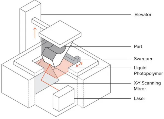
2.1.1 Stereolithography (SLA)
Stereolithography, commonly known as SLA, is an additive technology falling under the first category according to ASTM (2013). A build platform is
submerged into a polymer resin bath (tank). A single laser in the machine is directed at the bottom of the tank, drawing the required cross section shape as the resin solidifies. After the bottom layer is solidified, the build platform is moved along the Z-direction, so that a new layer of polymer resin fills the bottom. The same process is repeated until the final shape is obtained. The object could then be exposed to UV light in order to enhance material properties (Jacobs, 1992). Usually, support structures that are made of the same material are needed and
removed or dissolved at the end of the process. SLA is the oldest and one of the most used 3D printing technology due to its cost effectiveness (Hopkinson and Dickens, 2003).
Top Down SLA printers are usually used for industrial purposes, while Bottom Up SLA printers could be operated from a desktop. Most notable desktop printer manufacturer is FORMLABS while the most popular industrial printer
manufacturer is 3D SYSTEMS (3dhubs.com).
2.1.2 Direct Light Processing (DLP)
The second used technology in this category is Direct Light Processing, referred to as DLP. In comparison to SLA, DLP uses an identical method of production. Instead of drawing the desired cross section with a laser beam, a digital light projector screen flashes an image at the resin layer. Since images on projector screens are formed from pixels, this method results in end layers formed from small rectangular bricks known as “Voxels” (3dhubs.com). An entire layer of resin is solidified at once using the same projected image, causing DLP to result in faster print times than SLA.
Figure 6. DLP Setup (3Dprintingindustry.com).
2.1.3 Continuous Direct Light Processing (CDLP)
The main difference between CDLP and DLP is the continuous upward
is the curing of the resin polymer with LED lights and exposure to oxygen during CDLP.
2.2 Sheet Lamination
Sheet Lamination is defined by ASTM (2013) as an “additive manufacturing process in which sheets of material are bonded to form an object.” Highly detailed and colorful 3D objects are obtained from this method.
2.2.1 Laminated Object Manufacturing
Similar to other additive manufacturing techniques, sheets are cut by a laser beam in order to obtain the desired cross sections. These sheets are then placed layer by layer on top of each other and glued after being coated with an adhesive. The only present commercial LOM printers use paper sheets since they are cheapest and can be colored. Industrial printers are compatible with plastic foils and metal sheets.
2.3 Material Jetting
Material Jetting is vaguely explained by ASTM (2013) as the process by which “droplets of build material are selectively deposited”. It includes three additive technologies, discussed briefly below.
2.3.1 Material Jetting
This technology jets out a photopolymer from several (hundreds) printer nozzles layer by layer on a build platform. Each photopolymer layer is exposed to UV light, which causes it to harden, and eventually form the final object shape.
Supports built simultaneously are often needed and disposed of or dissolved at the end of the printing process. Most common manufacturers for material jetting printers are STRATASYS and 3D SYSTEMS. Multi-color, multi-material, products with various properties can be printed using this technology.
2.3.2 Nano-Particle Jetting
Nano-Particle jetting differs from the classical material jetting in the substance that is excreted by the printer nozzles. Instead of secreting a photopolymer, a liquid containing metal nanoparticles is secreted. The build temperature is then increased in order to evaporate the liquid and have a 3D object made up of the leftover metals. Common manufacturers for NPJ printers are XJET company, which use stainless steel or ceramics.
2.3.3 Drop on Demand
DOD printers are characterized by two print jets: one that jets a wax-like liquid which later hardens in order to form the 3D object, and another that jets
dissolvable support material. The cross section of the desired component is printed out by depositing the wax-like liquid in a pointwise fashion
(3dhubs.com). Each build layer is then skimmed in order to ensure a flat surface. This technology is usually used in order to produce castings and molds. Common DOD printer companies include SOLIDSCAPE, which utilize wax in their 3D products.
2.4 Binder Jetting
“Binder Jetting is an additive manufacturing process in which a liquid bonding agent is selectively deposited to join powder materials” (ASTM, 2013).
2.4.1 Binder Jetting
A binding adhesive agent is added to a thin layer of ceramic or metal -based powder materials. Agent droplets are deposited on the top of the powder material present on the build platform, causing them to bind together and solidify. The surface is then lowered and another layer of powder is sprayed with binding material droplets in an iterative process. This technology often produces brittle material which is why it is most convenient for aesthetic applications
(architectural models, mini-models, packaging). 3D SYSTEMS, VOXEL, and EXONE are the most common manufacturers of BJ printers.
Figure 9. Binder Jetting Model (additively.com).
2.5 Powder Bed Fusion
Power Bed Fusion (PBD) is “an additive manufacturing process in which thermal energy selectively fuses regions of a powder bed” producing solid layers (ASTM, 2013).
2.5.1 Selective Laser Sintering
SLS is an additive technology falling under the PBD category. A plastic powder is spread across the build surface, which is then sintered by a laser beam producing a certain solid cross section. The build platform is then lowered a layer thickness, and a new layer of powder is spread on top. The process is repeated until the final product is obtained. The product is usually covered with the powder material, and further post-processing is required to smoothen the surface. (Pham and Gault, 1997).
2.5.2 Multi Jet Fusion
Multi Jet Fusion, commonly referred to as MJF, is a combination between SLS and Material Jetting. Ink nozzles, attached to a movable carriage, secrete binding agent on the build surface where plastic powder is spread. A sintering inhibitor is then applied from another nozzle at the edges of the fused material. Strong InfraRed rays then sinter the cross section where the fusing agent was applied, causing it to solidify, leaving the other areas untouched. HP is the main manufacturer of MJF printers.
2.5.3 Direct Metal Laser Sintering/Selective Laser Melting
SLM and DMLS are Power Bed Fusion technologies that work in a similar fashion to Selective Laser Sintering technology. The main difference is that a metal powder is used instead of a plastic one. SLM causes the metal powder (single component e.g. Aluminum) to completely liquify (melt), while DMLS causes the metal powder (Alloy) to increase in temperature until it is chemically fused. Support structures are usually needed in order to prevent warping and twisting caused by the metal residual stresses. EOS, based in Munich, Germany, was the first to produce DMLS printers, commercially available since 1995 (Khaing et al, 2001). A couple of competitors have entered the market since then, 3D SYSTEMS and SINTERIT which also produce desktop compatible printers.
Figure 13. DMLS Machine (lasersintering.com).
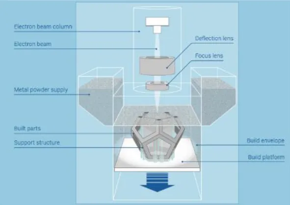
2.5.4 Electron Beam Melting
EBM is a technology close to Selective Laser Melting and SLS. An electron beam is directed at the metal powder, causing it to melt, fuse, and solidify according to a traced cross-section. Although EBM is faster than SLM/DMLS and uses much less energy, its end product is of a lower quality. Support structures are not
necessarily needed since less residual stresses lead to less deformations. One main drawback of this technology is that the printing system’s build surface and
powder have to be placed in a vacuum chamber, and only conducting materials can be used. ARCAM patented and id the main manufacturer of EBM technology and printers which use Titanium and Cobalt-Chrome powder. (Sing et al, 2015)
2.6 Directed Energy Deposition
Directed Energy Deposition (DED) is “an additive manufacturing process in which focused thermal energy is used to fuse materials by melting as they are being deposited”. (ASTM, 2013)
2.6.1 Laser Engineering Net Shape
LENS is one of the newest additive technologies. A laser head concentrated at a specific point creates a “melting pool” where a nozzle head and inert gas tubing deposit the powder to be melted and solidified. A metal surface is usually used, and this technique is mostly utilized for repairing by adding material to a certain object (Griffith et al, 1996). OPTOMEC is the main LENS printer manufacturer.
2.6.2 Electron Beam Additive Manufacturing
A technology originally built for space, EBAM is the second DED printing technique. An electron beam is used as a heat source in order to weld metal wires or powder materials, resulting in a metal end product. Electron beams operate in vacuum and are more efficient than laser beams. The main manufacturer of EBAM printers are SCIAKY INC which utilize titanium, steel, aluminum, or copper.
Figure 16. EBAM Process (Sciaky.com).
2.7 Material Extrusion
Material Extrusion (ME) is “an additive manufacturing process in which material is selectively dispensed through a nozzle or orifice.” (ASTM, 2013)
2.7.1 Fused Deposition Modeling (FDM)
Fused Deposition Modeling (FDM), also referred to as Fused Filament Fabrication, is the only ME technology currently in use. Solid thermoplastic material in filament form is heated in the printer nozzle head as it is pushed out in a dense melted form. The printer moves the nozzle according to the desired cross-section, forming layers above layers of solidified material until the final object is obtained. It is the most widely used technology, and concrete printing is based on the same extrusion concept. (Zein et al, 2000).
Most common manufacturers are STRATASYS, ULTIMAKER, MAKERBOT, AND MARKFORGED, which use a variety of materials ranging from nylon and plastic to wood and steel.
3. 3D Printing in the Construction Industry:
After the industrial revolution, living standards changed drastically. Robotics is now
implemented in a variety of manufacturing applications replacing complicated and possibly dangerous human production activities. This has caused the prices of goods and services to greatly decrease while their quality increases. This however does not apply to the construction industry. (Khoshnevis, 2004).
Until today, the construction industry is still heavily labor-oriented, leading to the rise of problems with quality, productivity, safety, and skilled labor (Hwang and Khoshnevis, 2004). Several attempts at automation and robotics integration started in the US and Japan, however, they were not very successful since the industry was too dependent on processes not adaptive to automation technologies (Warszawski and Navon, 1998). The need for a technology that could accomplish quality, safety, and productivity targets greatly increased in the past decade since it was obvious that the construction industry is lagging behind.
3D printing, an automated layer-by-layer production process, has been adopted for more than two decades in the manufacturing industry. As discussed previously, various 3D printing
techniques and methods have been developed, each utilizing different specific materials. Due to their high viscosity and fast melting and solidification properties, plastics, metals, and ceramics have been most widely used. Creating complex models using 3D printing takes just as much time as any other model with no additional cost. This made 3D printing suitable for building complex small-scale architectural models. Consequently, building real large-scale architectural
goals to many companies after years of process evolution and refinement. A few companies have been able to develop and test printers for concrete or concrete-like substances. Years of testing and trial and error are still ahead of us. In the following, different concrete and concrete like substances printers will be discussed, as well as their main operators and manufacturers. It is useful to shed light on the idea that 3D printing works by slicing a 3D Computer Aided Design (CAD) model into layers of 2D models, which are subsequently sent to the printer for
construction.
3.1.Contour Crafting
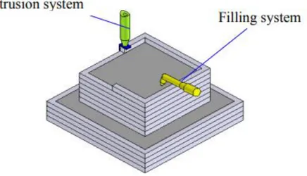
“Contour Crafting Technology adapts Rapid Prototyping capabilities and extends them to the field of large-scale construction.” (Hwang and Khoshnevis, 2004). It is “an additive fabrication technology that uses computer control to exploit the superior surface-forming capability of troweling in order to create a smooth and accurate planar and free from surfaces out of extruded materials” (Zhang and Khoshnevis, 2013). Developed in 1998 at the University of Southern California, Contour Crafting is a 3D printing technology patented by Behrokh Khoshnevis. It is originally designed in order to print large scale models and usable structures for buildings. The whole design is based on the extrusion of contours and consequent filling inside the printed layers by two different nozzles as can be seen in the figure below.
Figure 20. Extrusion and Filling Mechanisms (Hwang and Khoshnevis, 2005).
A smooth object surface is obtained through the extrusion process, where the flow is constrained horizontally and vertically by trowels. The side trowel orientation can be conveniently changed dynamically in order to get a better surface fit of different layers. The side trowel also determines material thickness and allows for thick material decomposition, leading to a much faster process, especially important for building big structures. The outer and top surfaces of outer edges are
first created through the extrusion process. The smoothness of each layer is guaranteed by the top and side operating trowels.
Figure 21. Single Nozzle with Trowels Assembly (Hwang and Khoshnevis, 2005).
The surface finish quality of the printed object is determined by the troweled external surface of each layer. It is important however to also have a smooth top surface for better material bonding and layer addition. The last layer top troweling determines its finish. After the boundaries are created, the extruded object can then be filled with a mortar mix as shown in the figure below.
Figure 22. Material Filling Using a Multiple Nozzle System (Hwang and Khoshnevis, 2005).
Materials used in Contour Crafting range from polymers to ceramic slurries and cement. One of the most interesting characteristics of Contour Crafting is that materials with larger aggregates and reinforcements could be printed (Khoshnevis, Hwang, Yao, & Yeh, 2006). This could be key to producing fiber reinforced 3D concrete structures using the Contour Crafting printer. The nozzle may have single or multiple outlets, enabling the printer to work on several sections at the same time. By deflecting the nozzle, non-orthogonal surfaces such as domes and vaults can be created (Khoshnevis, 2004).
Figure 23. Multiple Outlet CC Printer Model (contourcrafting.org, 2014).
The aim of the research done at the University of Southern California (Khoshnevis, 2004) was to first create a single CC printed residence structure in one go. “A gantry system carries the nozzle system and robotic arms move on two parallel lanes on the construction site. Adding an
additional support-beam picking and positioning arm could produce conventional structures (at openings). Integrating automatic embedment of reinforcement is studied as well.” (Wolfs, 2015). The research then proceeds to the next phase where complete buildings could be realized by
automated systems for plumbing, electrical and communication wiring, beam installation, and painting and tiling. The last phase aims at making Contour Crafting the main process for construction, providing active feedback through its sensory systems and information
technologies. Before reaching this stage, many obstacles have to be overcome. The CC printer has a lot of limitations, some of which include (Zhang and Khoshnevis, 2013):
- An optimized tool path is required as input in order to get the most out of the technology. - During construction, each nozzle has to completely finish a layer before moving to the
next, which imposes some time and material limitations.
- For multi nozzle systems, collision between printer nozzles has to be avoided.
- Subsequent constraints imposed by layer adherence properties, solidification properties, slump, and support ability of lower layers.
“A tool path of Contour Crafting for a specific structure must describe the position,
orientation, velocity, and deposition rate of the nozzle in the entire construction period. This information is converted into a sequence of machine tasks and then fed to the Contour Crafting machine.” (2013). This is done after slicing a 3D CAD model into a sequence of 2D layers, as can be seen in the figure below.
The 2D model is then fed to the CC printer, along with the required parameters. The printer’s main structure then supports and guides the extrusion system throughout the whole process.
Figure 25. CC printed Structures and Machine (top right) (Lim et al, 2011).
With the possible use of Sulphur concrete and sintered moon soil (aka Regolith) as a printing mixture, NASA has funded Contour Crafting research for its use as a Lunar Construction Method. Human intervention would be minimized, leaving less margin for errors and better safety measures. (Khoshnevis & Zhang, 2012).
3.2.D-Shape:
Based on Z-Corp’s Binder Jetting 3D printing process, Dini (2006) proposed “a method for automatically producing a conglomerate structure and apparatus therefor”. In other words, he aimed at producing larger scale objects, eventually buildings, by spraying binding material (e.g. epoxy resin, cross-linking polyurethane) on a granular material bed (Dini patent, 2006). By further improving his Monolite process, Dini developed what is known as D-Shape 3D printing. A layer of sand-like material with predetermined hardening properties is laid on the build surface and compacted to the desired layer thickness. Multiple nozzles (300) are then moved around by the printer arm, releasing binder material according to the desired cross-section, hardening the layer of grains below it. The build surface is then moved along the vertical axis, releasing an added layer of granular material, and repeating the same process until the final object is achieved. The maximum current printer size is 6m*6m*6m.
Figure 26. 5m*5m*5m D-Shape Printer (Krassenstein, 2014).
Although there is no specific reason as to why D-Shape has not been employed on-site, it is considered a gantry based off-site dry manufacturing process. Being a powder-based process, the unconsolidated material is used for supporting overhangs and “freedom” features (CITATION). After experiencing problems with the first epoxy resin characteristics, a Magnesium based adherent was developed that solidifies sand, giving it suitable properties.
Architectural pieces of around 1.6m high and sculptures (shown below) were first produced using this technology.
Figure 27. D-Shape printed Sculptures (d-shape.com).
Binder deposition rate is one of the main factors affecting printing speed. In addition to this, layer thickness, which varies between 4 and 6mm, is another major contributing factor to printing speed. Since printing is done in a “pool” of sand, the final object has to be retrieved or dug out of the powder bed. This property in particular poses one of the main problems for D-Shape 3D printing, a large volume of material has to be deposited in the build area, and
very large structures could not be realized (Lim et al, 2011?). It is also worthy to note that maximum object size cannot be larger than the printer (6*6*6 m currently). Nevertheless, a small complete house (depicted below) was printed in one go using the D-Shape printer.
Figure 28. D-Shape Printed House (d-shape.com).
As can be seen in the above picture, D-Shape printing finish requires grinding and polishing if a smooth surface is desired (CITE). Other issues with the D-Shape printing technology relates to the binder penetration through each layer, as well as “bleeding” that could happen next to sprayed areas (dripping adherent material). ESA, a space administration agency, has also expressed interest and funded D-Shape technology for its possible use to build outpost structures on the moon.
3.3.3D Concrete Printing:
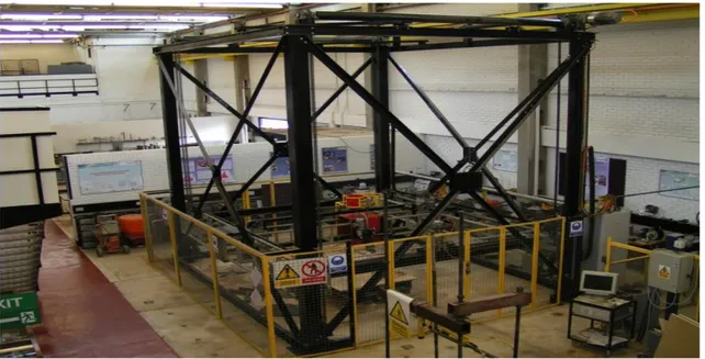
Inspired by advances in 3D printing technology, a novel printing process was developed at Loughborough University called Concrete Printing. Concrete Printing, like Contour Crafting, is an extrusion-based 3D printing technique, with a viable future in the construction industry. The main difference is that while CC extrudes a mold and then fills it with concrete, CP is a mold-free extrusion process (Lim et al, 2011). As the previous 3D printing processes, the first step in Concrete Printing is providing the printer with a layered representation of a 3D CAD model. Nozzle position, movement, and material flow are all predetermined and fed to the printer with the layered model. The first prototype printer consists of a 5.4m by 4.4m by 5.4m frame “and a printing head on a mobile horizontal-beam which moves in the y and z direction while the printing head moves in the x direction only.” (Lim et al, 2009).
Figure 29. Concrete Printing Machine (Lim et al, 2011).
The printing process consists of three main stages, being: material preparation, delivering, and printing. Materials based on cement and concrete have been used for the prototype
modeling due to their known properties. The former is used for build material, while the latter is used to create dissolvable or removable structural supports during printing. Constant workability and control of materials are of essential importance during the printing process. Not many details have been provided about the types of mixes used, however, according to Lim et al (2012), workability consistency is provided by a retarder admixture. It is further mentioned that the material mix consists of 54% ash, 36% reactive cementitious compounds, and 10% water by mass (Lim et al, 2012). According to Le et al (2011), the binder material is a mix of CEM 1 cement, fly-ash, and undensified silica fume. Shrinkage and deformation in the plastic state are reduced by the inclusion of polypropylene micro-fibers (Bos, Wolf, Ahmed, and Salet, 2016). Due to the possible formation of voids during printing, material strength is reduced by around 20% (Lim et al., 2011).
Materials are fed to the printer in small batches since it is important to maintain freshness and maximize material strength. In addition to this, the delivery path should also be as short as possible in order to guarantee workability of printed material. After mixing the material, it is shortly stored in a “pump located outside of the rig to deliver material to the nozzle through a hose. A small hopper is installed as a buffer zone on the top of the deposition device which in turn delivers the materials to the desired location. In the beginning of printing, the head is located in the recharging position to fill the materials into the hopper. When the amount of material in the hopper is reached to the pre-defined low level, then the printing head moves back to the recharging position to refill the hopper.” (Lim et al, 2011).
Figure 30. Delivery and Refill Processes (Lim et al., 2011).
A specific tool path, as well as other parameters such as flow rate and movement speed are predetermined. In the first trials, a flow rate of around 1.4 Kg/min was used to accommodate the small nozzle diameter (9mm). Print direction and strength are relatively independent due to the crystallization process through which cement hydrates. Nevertheless, this also means that there is a limited time during which concrete should be printed, before it sets. “The critical issue is the consistent rheology of the fresh material to enable it to move smoothly through each part of the delivery process, yet retain sufficient rigidity once it leaves the nozzle.” (Lim et al, 2011). Concrete mix has to flow enough in order to exit the printer nozzle, however, it must also be able to withstand the forces exerted by upper layers when wet with minimal slump, and different higher exerted forces when dry. Several objects were successfully printed using this 3D technology, initially using gypsum-based material. These served as test objects for calibrating nozzle size, print speed, and surface finish. It was observed that decreasing the bead size would increase the printing resolution. After a few modifications, the following objects were printed.
Figure 31. 3D Printed Silo (Lim et al, 2011) Figure 32. 3D Printed Bed (Lim et al, 2011).
The first notable structure made using 3D Concrete Printing is Loughborough University’s wonder bench, seen in the picture below.
3.4.YingChuang:
Founded in July 2003, YingChuang Building Technique is the first industrial company to
successfully 3D print houses around the world. Large scale building components are built at high speed inside their factories, and later moved on site. Their printing technique is similar to
Contour Crafting, where inner and outer leaves are printed, with a zig-zagged shape in between. Reinforcement is added during the printing process between layers as observed in the figure below.
Figure 34. YingChuang 3D Printing Technology (winsun3d.com).
A 150 by 10 by 6.6 m printer was developed, along with several possible printable mixes. Glass reinforced gypsum (GRG) was the first patented product by its father company Winsun in 2002, used for 3D printing internal decoration of theaters, stadiums, and offices. The second patented
material was fiber reinforced plastic (FRP), used to 3D print furniture. Special Reinforced Concrete (SRC), also patented by the company in 2006, is used for building internal and external parts of personalized buildings. Floors, walls, and roofs of building may also be 3D printed using the most recently patented (2007) Crazy magic stone (CMS). Multiple houses, a five-story apartment block, and a 1,100m2 mansion were realized by YingChuang from 2008 to 2014.
3.5.HuaShang Tengda:
A major competitor for YingChuang on the Chinese market is construction company HuaShang Tengda. After years of developing their 3D concrete printer, HuaShang Tengda was able to build a 2-story 400m2 house, completely 3D printed. Their technique differs from others in that the frame of the house, complete with the rebar support and plumbing pipes, is first erected. The machine with a fork-shaped extruder then lays C30 concrete on both sides of the structural element, encasing it within the walls. It took 45 days to completely finish building the 2-story house shown in the picture below.
3.6.TotalKustom:
Andrey Rudenko, a contractor from Minnesota, was able to build a 3D printer which uses a technique similar to Contour Crafting. Main difference between the two methods is that Rudenko uses much less layer height (5mm), which, although slows down the printing process, could result in more detailed structures with better finish. According to Rudenko, cheap, fast, building is not the main concern, contrary to the previously introduced Chinese companies, but being able to completely automate the building process from all aspects (e.g. plumbing, insulation, electrical wiring…) using 3D printing is. No details about the concrete mix used is available, however, a miniature castle in Rudenko’s backyard, and a hotel suite in the Philippines were successfully 3D printed by Andrey Rudenko and his team. The abovementioned structures are depicted in the images below. (TotalKustom.com)
Figure 36. 3D Printed Suite (totalkustom.com). Figure 37. 3D Printed Miniature Castle
Several other companies have also had some successful 3D printing initiatives, such as CyBe Additive Industries which is based in Netherlands and developed a mortar reaching bearable strengths within minutes to use for CC (Anderson, 2015).
BetAbram, a Slovenian company, successfully 3D printed a concrete staircase, and are further developing their printers for commercial use and availability. They are also working on 3D printable concrete mixtures, although additional mix information is not provided (Alec, 2014). A subgroup of Rael San Fratello Architects known as Emerging Objects have developed a printing technique similar to Dini’s D-Shape using a fiber-reinforced concrete mixture. It is made up of small aggregates, in addition to the cement and reinforcement, with a variety of adhesives that improve workability. An alcohol-based water-soluble binder is first applied to the dry bed of mix. The synthetic polymer contributes to the mix’s adhesive and mixing abilities, while providing it with high tensile capacity. Additionally, it aids the curing phase in terms of speed, and it increases the density of the mixture, causing added flexural strength. Hydration of the material and better connection between the fibers and cement mix is achieved by adding a secondary binder. The obtained hybrid concrete polymer is shown in the pictures below:
Figure 38. Earthquake Resisting Quake Column Figure 39. Water Absorbing “Cool Brick”.
(emergingobjects.com) (emergingobjects.com)
Similar to D-Shape, the unused dry powder acts as a supporting structure during the printing process and the structure has to be removed from the powder bed. The material used is completely recyclable, however, accurate information about its composition is not available.
4. Printable Concrete Characteristics:
“The emphasis on reduction of construction time and production costs has profound influence on construction process that has led researchers to explore 3D concrete printing.” (Van Zijl et al, 2016). Concrete 3D printing has experienced a lot of advancements in the past decade, with more research and efforts being put into perfecting this technology.
Figure 40. 3D Printing Process (Paul et al, 2017).
Formwork-free 3D printing provides a big level of freedom in structural geometry design, and reduces formwork costs and construction duration. These factors, in addition to the fact that less labor would be needed, would lead to huge savings economically (Nerella et al, 2016).
3 main techniques have been successfully developed and tested for building large-scale building components and structural elements. The abovementioned extrusion-based techniques which are Khoshnevis’ Contour Crafting and Loughborough University’s Concrete 3D Printing, and selective binding techniques such as Dini’s D-Shape, have been discussed in the previous section. The main obstacles of 3D concrete printing are developing a suitable automated printer with optimal nozzle diameters and printing speeds, as well as developing a suitable concrete or more efficiently a mortar mix (since large aggregates >4mm are not used). Most advances and patents in this field were made in China and the United States, where the private sector is the most advanced when it comes to 3D printing. Due to this reason, concrete mix specifications are not made public, and few indications about their composition are given. Research at a number of universities namely the University of South California (US), Loughborough University (UK), and Eindhoven University of Technology (Netherlands), have cultivated some interesting usable results concerning different concrete mix compositions and early stage characteristics.
While striving for the perfect concrete mix, some important conditions and limitations have to be kept in mind (Nerella et al, 2016):
- Consistency Retainment for longer periods of time;
- Pumpability;
- Extrudability and Buildability (ability to withhold form geometry under pressure from upper layers);
- Compressive, tensile and flexural strengths in parallel as well as perpendicular directions to layer-interface-plane;
Consistency of concrete is defined as the ability of concrete to flow. Concrete consistency is measured by means of the slump test which measures the ability of concrete to start flowing (Kosmatka et al, year). A metal cone, open from both sides is placed on a horizontal surface, concrete is then place inside, and the cone swiftly removed. The time concrete takes in order to “slump” or fall a specific vertical distance is then measured (Ferraris, 1999).
Figure 41. Slump Test Representation (Ferraris, 1999).
When it comes to layer-by-layer concrete placement, a low slump is required in order for layers to maintain their shape and thickness throughout the printing process. As slump decreases, hydration of concrete is allowed to take more time, however, if the hydration process of concrete is fast, a larger slump could be allowed. Pumpability, which is related to the speed of hydration of concrete, is the ability of concrete to be pumped out of the printer nozzle. Mixes with very low water to cement ratios set faster and are stickier, making them more convenient to hold as layers, but also nearly impossible to pump from a printer nozzle (Paul et al, 2017).
Keeping in mind the importance of pumpability, concrete printed in the form of layers has to be able to withstand pressure from higher layers and form a good connection between them. A high water to cement ratio would cause the concrete to slump, therefore additives which guarantee workability with a low slump and high early strength are needed (Feng et al, 2015).
Setting time is defined as the time needed for concrete to pass from a liquid phase to a solid phase and gain its full mechanical strength. Printable concrete comes out in a dough-like fashion, and needs to set fast enough for the concrete to gain strength in order to withstand layer addition, but also slow enough in order to guarantee a connection between different layers.
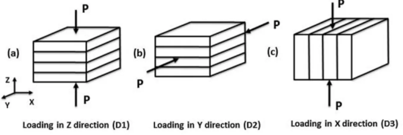
“One of the main disadvantages of printed structures is their mixed isotropic and anisotropic properties in different direction unlike cast specimens that is taken to have isotropic properties in all directions.” According to Paul and colleagues (2017), printing direction and time gap between printing layers are important factors in developing the load bearing capacity of an object.
Figure 42. Force Direction (Nerella et al, 2016).
Tests done by Nerella and colleagues (2016) show that better compression strength is obtained along the D1 and D3 direction in layer based extruded concrete than in mold-cast concrete. An
increase of 10% is obtained along D1 direction, and an increase in 14% is observed along the D3 direction (2016).
Similarly, flexural tests done by Nerella and colleagues (2016) show that an increased flexural resistance of 16% along D1 and 14% along D3 is observed in printed concrete compared to mold cast concrete.
Figure 43. Flexural Test Loading (2016).
In similar tests, Feng and colleagues (2015) obtained higher compression resistance along the parallel direction (D1) than along the perpendicular directions (D2 & D3).
The tensile strength along the D1 (z-axis) direction depends on the bond strength between the layers of concrete.
These results however may vary from batch to batch and from one position to the other. Since hydration is a continuous process in time, concrete becomes harder to extrude as it reaches its setting stage. Freshly mixed concrete used for bottom layers is still in a convenient plastic phase for extrusion. In addition, “the hardening properties of concrete may differ significantly if concrete is disturbed after its plastic phase.” (Paul et al, 2017).
Loughborough University’s lab conducted some tests on samples collected from the printed concrete wall and a slab using the 3d Concrete Printing technology, and compared it to mold-cast concrete. Regarding the wall, the compressive strength of mold-cast specimen (107 MPa) was 30% higher than the printed wall. However, the printed slabs showed a 5-15% loss of
compressive strength compared to the mold-cast concrete (91-102 MPa). These results varied with the orientation of the load, depending on the orientation of the printed layers, having the lowest strength value when the load is applied parallel to the layers (Le et al, 2011).
Unlike in compression, printed specimen showed an increase in flexural strength compared to the mold-cast ones when bottom tension was in alignment with the printed filaments. Values ranging between 13 and 16 MPa were obtained for the printed concrete, compared to the 11 MPa
obtained from mold-cast samples. Unsurprisingly, flexural strength greatly decreased (up to 36%) when the tests were done using a load perpendicular to the layers, as compared to a mold-cast subject (7 MPa). The increase in flexural strength when the loading is aligned with the layers is due to the fact that the bottom layers of concrete are more compacted, and could withstand more tension (Le et al, 2011).
Tensile bond strength is another important studied factor, as an adequate bond is required between the layers. Subjects with printing time gap of more than 15 mins did not bond well, and
therefore failed at layer interface, whereas subjects printed within that time lapse had adequate bond strength and experienced a material failure (Le et al, 2011).
Due to the abovementioned conditions and limitations, fresh printed concrete rheology is of essential importance for the success of the process. Rheology is defined as the study of the flow of “soft solids” and plastic like material (Schowalter, 1978), like concrete in its early stages. According to Kosmatka and colleagues (1994), three main terms are significant when dealing with concrete rheology; workability, consistency, and plasticity. “Workability is a measure of how easy or difficult it is to place, consolidate, and finish concrete; Consistency is the ability of freshly mixed concrete to flow; and Plasticity determines concrete’s ease of molding”
5. Mix Designs:
Based on the abovementioned properties and characteristics of concrete, different concrete mix designs were developed in different labs.
The Contour Crafting mix was developed at the University of Southern California after several trial and error experimentation. The following mix was achieved:
- Type II Hydraulic Portland Cement 37%
- Sand 41%
- Water 19%
- Plasticizer 3%
Experiments show that this mix results in a mean compressive strength of 18.9 MPa. Fine aggregates (sand) are utilized in order to accommodate for the small nozzle diameter and add strength to the mix, while a superplasticizer is used to increase the workability of the mix (Hwang and Khoshnevis, 2005). No additional information is available about the concrete mix used in order to fill the CC “molds” and specifics.
Other cement-based mixes are particularly used in the Concrete 3D Printing technology. Loughborough University’s lab developed and tested several concrete mixes, suitable for high printing resolution. Five mixes were tried, shown in the table below.
Table 1. 3D Concrete Printing Trial Mix Proportions (Le et al., 2011).
Sand with a maximum diameter of 2 mm was added to the binder component made up of cement CEM I 52.5, undensified silica fume, and fly ash. The mixture includes reinforcement consisting of 12/0.18 mm length/diameter polypropylene micro fibers. Mix 4 was found to be the best mix, considering it has the lowest binder content, with the supplier-recommended dosage of 1.2 Kg/m3 of reinforcement. A 1.5 and 0.26 sand-binder and water-binder ratios were used respectively. The mix also contained a superplasticizer with 1% by weight of binder, and a retarder with 0.5% by weight of binder, extending the open usable time up to 100 minutes.
A slightly higher density (2350 Kg/m3) is obtained in the printed subjects than in the mold-cast subjects (2250 Kg/m3) (Le et al, 2011).
6. Reinforcement in 3D Printable Concrete:
While Portland Cement-based materials exhibit high compressive strength properties, their tensile and flexural strengths are notably less (Hambach & Volkmer, 2017). In order to overcome this deficit in traditional construction, reinforcing steel bars are usually used.
Construction codes present the minimum and maximum amounts of reinforcement that should be used in order for the structure to attain a good tensile and flexural capacity, as well as ductility properties pertaining to the recommended mode of failure, and an increased stiffness.
Automation of the construction industry on the other hand, requires a new reinforcement approach that provides structural stability through high strength and ductility (Panda et al, 2017).
Various types of reinforcement have been utilized and tested in the current 3D concrete printing industry and laboratories. Chinese company HuaShang Tengda “adopts a method of erecting a steel frame on-site and printing around it”, while its rival company Winsun has not revealed any particular details regarding the structural role of concrete and its reinforcement, although few pictures suggest that bars of reinforcement may have been used between the printed contours (Bos et al, 20016). Lim and colleagues (2012) printed the concrete “wonder” bench at
Loughborough University by leaving hollow openings over the height of the structure for post-tensioning using prestressed bars fed after printing, ameliorating its tensile and flexural capacity, although the overall ductility of the structure is not enhanced.
Meanwhile in Netherlands, construction company BAM Infra, with the help of the Eindhoven University of Technology laboratories, erected the first 3D printed concrete bridge seen below,
open for cyclists and pedestrians. Steel reinforcement was embedded during the printing process, as well as layers of reinforcing steel wires placed above each layer of printed concrete for
increased ductility, tensile, and flexural strength.
Figure 45. 3D Printed Pedestrian Bridge – Gemert, Netherlands (3dprint.com).
The most currently researched form of reinforcement is fiber reinforcement, being the most efficient and requiring least time for complete automation. Several factors have to be considered, such as nozzle opening diameter, material of reinforcement, maximum reinforcement length and thickness, as well as reinforcement orientation. Carbon, glass, and basalt, in addition to steel and polymer reinforcing fibers have been used by some authors. With a fiber length ranging between 3 and 6mm, and a diameter of 7 up to 20 µm, fiber reinforced products show an increased flexural strength from 10 MPa to 30 MPa. Fiber alignment and orientation are imposed by the
printing path, especially when a nozzle opening diameter smaller than the reinforcement length is used. This leads to enhanced flexural and tensile properties along a specific predetermined
direction, making the print path an important aspect to account for (Hambach & Volkmer, 2017).
III. Experimental Program
Very few literature articles on 3D printable concrete testing have been published due to the recency of this technology. Most tests are done in private labs by private companies, and therefore their methods and results are not available for the public. Academic papers show results pertaining to tension and compression in addition to shear, however, a specific description of testing apparatus and techniques is not included. Based on Mettler and colleagues’ work on Cement and Concrete Research (2016), a concrete testing framework similar to theirs was adopted in the current study. Evolution of strength and failure of SCC during early hydration (Mettler et al, 2016) utilizes a set of non-standard mechanical tests in order to distinguish between two regimes in the evolution of self-consolidating concrete strength. “In the first, the material is capable of undergoing large localized plastic deformations, followed by a transition to cohesive frictional material behavior dominated by crack growth” (Mettler et al, 2016).
Although the tested concrete is not specific to 3D printing, its use in robotic fabrication techniques makes its early stage properties similar to those of printable concrete concerning rheology and workability, and the tests relevant. Mettler and Colleagues’ article (2016) describes 6 test setups namely Penetration (a), Punch-Through (b), Shear (c), Compression (d), Tension (e), and Bending (f). Strength evolution assessment in time was done by tracing the force-displacement curves at different ages since mixing, which results in different hydration states. Failure patterns were then assessed qualitatively, revealing important insight into the behavior of the material at different times since mixing. The different test molds used, as well as their
Figure 46. Experimental Testing Setups (Mettler et al, 2016).
According to Mettler and Colleagues (2016), shear, compressive, and tensile strengths are represented by the Von Mises criterion in the first principal regime, when the material is ductile. Presented below are the adopted experimental setups, for shear and tension, based on the above presented molds. It is worthy to note that both molds were made from cut and dimensioned transparent plexiglass plates of 10mm thickness. Plates were then assembled and fixed together using steel screws at their designated positions.
1. Shear Apparatus:
Similar to the Jenike Shear Cell (ASTM D6128-14), but utilized in a horizontal fashion rather than vertically as described in the article (Mettler et al, 2016), the shear mold used for the current study is made up of two compartments, one horizontally displaced at a constant rate, while the other fixed, measuring its resistance. A steel rod directly translates the horizontal movement of the testing machine to a steal plate fixed in the middle on the mold. Two horizontal plates, each attached to one compartment, “produce a notch for cleaner shear conditions at the fracture plane” (Mettler et al, 2016). Side railings were utilized in order to avoid any unwanted horizontal movement. Seen below are a dimensioned figure of the setup, exported from AutoCAD, and images of the real model.
Figure 48. Empty Shear Testing Apparatus
2. Tensile Apparatus:
In the current study, as in the study of Mettler and colleagues’ (2016), a mold of two separable parts was utilized for the tensile test implementation. Since fresh concrete cannot be clamped, a lot of “slipping” would result at the contact surface. Two rows and 3 columns of pins were therefore laterally attached to the side of the box in order to enhance shear transmission from the mold to the sample. “A round notch of radius R = 60 mm, reduced the effective cross section of the sample to Aeff = d*h with width d and height h.” (Mettler et al, 2016). For practical
purposes, two pipes with a diameter of 80mm, cut at a convenient chord location, were fixed to the movable part of the mold using silicon filling. During testing, one half is horizontally separated by clamping the pulling machine to a rod passing in the middle of two plates, each fixed to a side, as observed in the figures below. Two rails on each side ensure the straight movement of one tensile apparatus half, while the other half is fixed to the base plate. The dimensioned picture taken from AutoCAD, as well as pictures of the assembled apparatus are shown below.
Figure 51. Empty Tensile Testing Apparatus
3. Mix Composition:
Based on literature mixes, two mix designs were utilized for the current study. Having the same composing materials, different quantities and percentages of each material were used for each mix. Materials used are cement, blast furnace slag, sand, superplasticizer, steel reinforcement fibers, and water.
3.1.Cement:
Cement is defined by ACI (American Concrete Institution) 116R-00 as a binder that sets and hardens by chemical interaction with water. Since this study aims at producing High Strength Cementitious Composites, cement with a compressive strength of 42.5 MPa was used.
3.2.Grounded Blast Furnace Slag (GBFS):
Slag cement, a fine non-metallic product, consists essentially of “silicates and aluminosilicates of calcium and other bases which are developed in a molten condition simultaneously with iron in a blast furnace” (Slag Cement Association, 2013). It is used in order to replace a portion of the cement in the concrete mix, with the following measurable improvements according to the Slag Cement Association (2013):
- Better concrete workability
- Easier finishability
- Higher compressive and flexural
strengths Figure 53. GBFS (indiamart.com)
- Improved resistance to aggressive chemicals
- More consistent plastic and hardened properties
Since the current study aims at testing the early age characteristics of concrete to be later developed for 3D printing, concrete workability as well as finishability and compressive and flexural strengths are of main concern. Slag is therefore used for this study’s cement mix.
3.3.Sand:
In the current study, a high strength cementitious compound is required for testing. As mentioned earlier, the tests are being developed in order to eventually test a suitable mix for 3D printing. To that aim, coarse aggregates cannot be used, especially those bigger than the possible nozzle opening. Fine aggregates (sand), which lead to greater strengths and less shrinkage, are therefore utilized, sieved to obtain a maximum of 2 mm diameter.
3.4.Superplasticizer:
Superplasticizer is an admixture (e.g. material other than water, hydraulic cement, fiber reinforcement and aggregates) which aims at reducing the amount of water used (for better strengths) and increasing flowability (slump) as well as workability, without causing undue set retardation or entrainment of air in mortar or concrete (ACI 116R-00, 2000). GLENIUM, a polycarboxylate-ether-polymer-based superplasticizer produced by BASFTM is therefore used.
3.5.Fiber Reinforcement:
The advantages of fiber-reinforcement and its benefits have already been discussed in the literature review. For this study
READYMESH MR-200 steel fibers, of 0.22 mm diameter and 20 mm length, provided by AZICHEM, have been used.
3.6.Water:
Essential for forming the cement paste, water leads to the hardening of concrete through the hydration process. Water/Cement ratio is one of the most important factors in a concrete mix, and has drastic effects on early strength and workability. Different water/cement ratios were used
for the different mixes.
It is important at this point to keep in mind that the concrete mix developed and used for this study is not meant for 3D printing purposes, but close enough (of similar components) in order to assess the reliability of the assumed methodology.
4. Experimental Mix Design:
An excel spreadsheet with the following tables was used in order to obtain the used mix designs.
Data Input Rcm_28gg > 70 MPa Rcm_1gg >15 MPa Consistency S1, slump 0-40 mm Dmax 4 mm Cement CEM_II_42.5R (-)