Università degli Studi di Bologna
Anno Accademico 2010/11 Sessione III
FACOLTA’ DI INGEGNERIA
INTERNATIONAL MASTER COURSE IN CIVIL ENGINEERING
DICAM
Dipartimento di Ingegneria Civile, Ambientale e dei Materiali
TESI DI LAUREA in
Earthquake Engineering
SEISMIC RESPONSE OF TANK-FLUID SYSTEMS:
STATE OF THE ART REVIEW AND
DYNAMIC BUCKLING ANALYSIS OF A STEEL TANK
WITH THE ADDED MASS METHOD
CANDIDATO: RELATORE:
Matteo Tavano Chiar.mo Prof. Marco Savoia
CORRELATORE: Prof. Nicola Buratti
“Questa Tesi non ci sarebbe senza l’aiuto, la guida e la spinta di Nicola Buratti. Colgo l’occasione per ringraziare ed esprimere tutta la mia stima nei Suoi confronti. Ringrazio i miei genitori. Senza di voi questo percorso durato cinque anni non sarebbe mai
iniziato e questa Tesi finale spero possa ripagare almeno una parte dei vostri sforzi.
Ringrazio tutto il resto della family, in particolare Giulia, i miei compagni d’avventura Spacchio e Christian e tutti i miei amici. Grazie per l’aiuto e il supporto che mi avete sempre dato, chi in maniera diretta e chi in maniera indiretta. Per me è stato ugualmente importante. Ringrazio i Professori Alessandro Marzani e Luca Lanzoni, il cui incontro è stato fondamentale
nella mia carriera universitaria e per la mia formazione come ingegnere. Un grazie speciale al Bone e a Vania. Voi sapete perché.”
PART I: Methods of Analysis and Design of Liquid-Storage Tanks under Earthquake Excitation.
Keywords: Liquid-storage tanks; dynamic response; earthquake excitation; code provisions;
buckling of steel shells; elephant’s foot buckling.
PART II: Numerical Modeling and Dynamic Analyses of a Clamped Steel Tank.
Keywords: Finite element model, added mass method, time-history analyses, dynamic buckling,
Contents
Foreword ... XIII
Preface ... XV
PART I:
Methods of Analysis and Design of Liquid-Storage Tanks under EarthquakeExcitation.
1. Dynamics of tank‐fluid sytems ... 3
1.1 Possible failure modes ... 3
1.2 What’s behind the codes ... 8
1.2.1 System, assumptions and terminology ... 8
1.2.2 Governing equations and boundary conditions ... 9
1.2.3 Impulsive solution for rigid tanks ... 11
1.2.4 Convective solution for flexible tanks ... 12
1.2.5 Recast expressions ... 13
1.2.6 Fluid-tank interaction under assumed mode ... 15
1.3 Mehanical models ... 17
1.3.1 Analogues currently available in literature ... 17
1.3.2 Unanchored tanks – General remarks and mechanical models ... 21
1.3.3 Fluid-structure interaction ... 25 1.3.4 Soil-structure interaction ... 29 1.4 Draft conclusions and research needs ... 31
2. Review of codes provisions ... 35
2.1 Types of tanks ... 35 2.2 Rigid vs Deformable tanks ... 362.2.1 Basic assumptions and terminology ... 36
2.2.2 Eurocode 8: rigid anchored tanks ... 39
2.2.3 Eurocode 8: deformable anchored tanks ... 42
2.2.4 Eurocode 8: a simplified procedure for deformable anchored tanks ... 45
2.2.5 ACI 350.3 and API 650: concrete and steel tanks ... 48
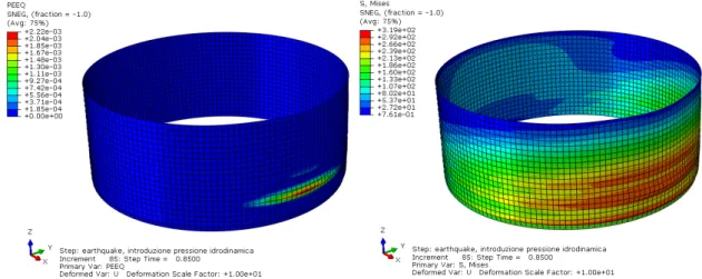
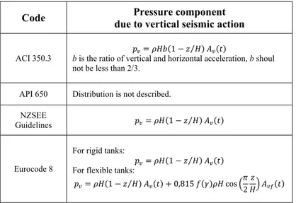
2.2.6 Vertical component of the seismic action ... 54
2.3 Anchored vs Unanchored tanks ... 63
2.3.1 Eurocode 8: unanchored tanks ... 63
2.3.2 API 650: self-anchored steel tanks ... 65
2.3.3 ACI 350.3: uplifting in concrete tanks ... 67
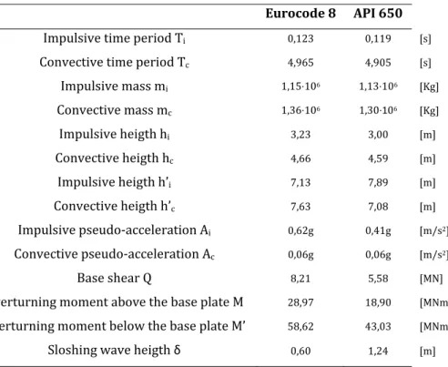
2.3.4 A worked example ... 68
2.4 Rigidly supported vs Flexibly supported tanks ... 70
2.4.1 Simplified model and its application to Eurocode 8 ... 70
2.4.2 A more rough procedure from NZSEE ... 72
2.4.3 ACI 350.3: the importance of the base connection ... 73
2.5 Assessment of codes guidelines ... 76
2.5.1 Seismic design loads ... 76
2.5.2 Damping ratios and behavior factors ... 77
2.5.3 Combination of impulsive and convective effects ... 79
2.5.4 Enhancement of uplift analysis in current standards ... 80
2.5.5 Soil-structure interaction ... 84
2.5.6 Combined action of horizontal and vertical earthquake components ... 87
2.6 Concluding remarks and future deepenings ... 89
3. Buckling of steel tanks ... 91
3.1 Buckling modes ... 91 3.1.1 Elastic buckling ... 91 3.1.2 Elastic-plastic buckling ... 93 3.1.3 Secondary buckling ... 97 3.2 Buckling in current standards ... 103 3.2.1 API 650 ... 103 3.2.2 A worked example ... 106 3.2.3 ECCS recommendations ... 106 3.2.4 Eurocode 8 ... 111 3.3 Design of a new tank shell for seismic loads ... 115 3.4 Concluding remarks and possible enhancements ... 119PART II:
Numerical Modeling and Dynamic Analyses of a Clamped Steel Tank.4. Finite element model ... 123
4.1 Tank model ... 123
4.1.1 Geometry, material and boundary conditions ... 123
4.1.2 Mesh details ... 124
4.2.1 The added mass model ...131
4.2.2 Added mass calculation ...133
4.3 Systems nonlinearities ... 135
4.3.1 Material nonlinearity ...135
4.3.2 Geometric nonlinearity ...136
5. Dynamic analyses ... 139
5.1 Modal analysis ... 139
5.1.1 Effect of pre-stress states on the impulsive modes of vibration ...139
5.1.2 Fundamental mode shapes ...142
5.2 Dynamic buckling analyses ... 144
5.2.1 Setting analysis ...144
5.2.2 Damping of the tank-fluid system ...146
5.2.3 Selection of the earthquake accelerograms ...147
5.2.4 Implicit time integration method ...155
5.3 Results ... 157
5.3.1 Observed tank behavior ...157
5.3.2 Dynamic buckling criterion ...161
5.3.3 Control node selection ...165
5.3.4 The influence of plasticity ...166
5.3.5 Failure modes ...171
5.4 Fragility curves development ... 174
5.4.1 Generalities on fragility curves ...174
5.4.2 New accelerograms and dynamic analyses ...176
5.4.3 Efficiency of ground motion intensity measures ...181
5.4.4 Fragility curves ...183
6. Concluding remarks ... 187
6.1 Conclusions ... 187 6.2 Future works ... 188Appendix A ... 191
Appendix B ... 193
Appendix C ... 195
Appendix D ... 201
Appendix E ... 207
Notation ... 215
Foreword
The earthquakes certainly represent one of the most critical events to the safety of industrial plants. In order to estimate the risk associated with the industrial plants, it is of crucial importance the knowledge of the vulnerability of each single component of the plant itself. In fact the structural collapse of just one of these components can trigger more catastrophic events such ase xplosions, fire, dispersion of toxic materials, water shortages, pollution or contamination, thus putting in danger the life of people who work in the plant and who live in the urban area where the plant is located. A key aspect in the risk analysis of industrial plants is the detailed knowledge of each component and sub-system, in terms of design installation and operation mode. This step gives a contribution to the ranking of facilities depending on hazard or the individuation of critical components that can dramatically increase the seismic risk. To this aim it is common to divide the system in a number of sub-systems that have to be analyzed in detail up to component level. These are the basic information for the construction of fault-tree and sequences of events. A review of the printout of design of the plant and all information relative to the boundary conditions is fundamental; at the same time the inspection of the plant is recommended to establish the maintenance status of the facilities and upgrade models for capacity estimation.
Industrial facilities show a large number of constructions and structural components. As materials are concerned, it is easy to recognize that both reinforced concrete and steel constructions are commonly used, even in combination like composite structures. Large installations can be characterized by use of pre-stressed members, especially when long spans are required. However, it is worth nothing that a large variety of functions have to be accomplished by structural components so that the latter can be classified as follows:
Building like structures: administration buildings, control buildings, substations, warehouses, firehouses, maintenance buildings, and compressor shelters or buildings. These are structures having a lateral force resisting system similar to those of building systems, such as braced frames, moment resisting frames or shear wall systems.
Non-Building like structures: such class of structures covers many industrial constructions and self-supporting equipment items found in a typical industrial plant, such as tanks, vertical vessels, horizontal vessels and exchangers, stacks and towers.
Foreword
Atmospheric tanks certainly represent the most spread and common component in an industrial plant; this is the reason why the present thesis is addressed to the increase of knowledge about their methods of analysis and design. Large-capacity ground-supported cylindrical tanks are used to store a variety of liquids or liquid-like materials, e.g. water for drinking and fire-fighting, petroleum, chemicals, liquefied natural gas and wastes of different forms. Satisfactory performance of tanks during strong ground shaking is crucial for modern facilities. Tanks that were inadequately designed have suffered extensive damage during past earthquakes.
Preface
Primary objectives of the thesis are: (a) to provide an overview of the salient aspects of the dynamic response of vertical, cylindrical, ground-supported tanks storing a homogeneous liquid; (b) to present different methods of analysis and design criteria, especially looking at the different codes provisions but also at alternative simplified procedures or innovative approaches given by other authors; (c) to set up a finite element model able to correctly represent the seismic behavior of the fluid-tank system; (d) investigate the complex phenomenon of buckling by means of dynamic numerical simulations and by establishing a buckling criterion; (e) to provide comments on the seismic vulnerability of liquid-storage tanks, using the results of dynamic analyses for the development of fragility curves. Secondary objectives are: (f) to create a sort of archive, based on which a designer can get design information/criteria according to the kind of tank he has to deal with; (g) to give a contribution in understanding the efficiency of different ground motion intensity measures with respect to the structural response (h) to suggest areas where possible future works should be oriented, especially looking at those topics where current design guidelines need further development.
The thesis is organized into two parts: I. Methods of Analysis and Design of Liquid-Storage Tanks under Earthquake Excitation; II. Numerical Modeling and Dynamic Analyses of a Clamped Steel Tank. Part I includes the first three chapters, where all issues relating to methods of seismic analysis and design of concrete and steel tanks are discussed in detail. In the second Part, including chapters four, five and six, a specific type of tank is chosen and a finite element model of it is set up. The results of modal analysis and dynamic simulations using the added mass technique for fluid modeling are presented, discussed and compared to those available in literature. Furthemore, based on these results, fragility curves are developed.
The first chapter deals with the theoretical basis of the dynamic behavior of liquid-storage tanks. Here, after a brief discussion on the possible failure modes, the governing equation and the analytical solution are presented. Then, the most important mechanical models (or analogues) used by the various international codes are introduced. The main studies of the most important scientist and engineers who investigated the seismic behavior of liquid-storage tanks are listed in chronological order. In this way the reader can have an idea of the successive developments on these topic and can understand the basis of the current sophisticated models. The modeling
Preface
aspects of the fluid-tank-soil system are covered, but since the subject is very wide and not yet fully understood, also suggestions on possible future works are given.
In the second chapter the main categories of tanks and the most important classification criteria are discussed. Here, attention is given to how the various international codes treat the different tanks categories. Codes provisions are analyzed and compared in detail. Such provisions are mainly related to the analysis and modeling aspects, but also to the design seismic forces calculation and verification criteria. The codes reviewed are: ACI 350.3, API 650 and Eurocode 8, but also New Zealand guidelines are sometimes mentioned. As the different guidelines are illustrated, also a numerical example is worked out through the chapter. The chapter ends with an assessment of code guidelines; here all the codes are compared and the results of the worked example are discussed. The quality of the different codes provisions is also assessed on the basis of numerical results and research works of many different authors. Areas where possible developments of the current codes should be oriented are indicated.
The third chapter is entirely devoted to the buckling phenomenon, which definitely plays a fundamental role in steel tanks design due to the small thicknesses used for this class of structures. First, an overview on the possible buckling modes with related causes and effects is given, especially looking at the correspondence between damages observed in real tanks during past earthquakes and analytical studies on simplified models performed by different authors. Then, attention is given on how buckling is treated by the various codes and deficiencies on the subject are highlighted. Since in the codes there is not a relevant theoretical background, but just simple formulas to be applied in order to verify structural elements, a great effort is done in this chapter in order to understand what is behind the above mentioned formulas and to relate them to the possible buckling modes. The API verification formulas are then applied to a worked example. Chapter three also involves very brief notes on possible methods to strengthen tanks against “elephant’s foot” buckling. Since these methods make use of innovative techniques that are still under verification, this could be an area of interest for future studies. The chapter ends with the proposal of a very simple but efficient method to preliminarily design the tank’s thickness against elastic-plastic buckling.
In the fourth chapter the tank model used for numerical computations is presented. All the details about geometry, materials, boundary conditions and sources of nonlinearity are highlighted. The method used to obtain a good finite element mesh on the tank is discussed. The added mass technique used to model the fluid is shown and the added masses are calculated explicitly.
Preface
The fifth chapter can be considered as the central chapter of the second part. Here, the type of dynamic analysis used to study the buckling phenomenon is explained in detail, from the governing equation and the numerical method used to solve it to the criterion chosen to select the earthquake accelerograms. The results of the dynamic buckling simulations are presented, compared and discussed in details. Prior to the nonlinear dynamic simulations, a modal analysis is also performed in this chapter, with the aim of studying the dynamic properties of the model. At the end of the chapter, the results obtained from the dynamic analyses of the added mass model of the tank are used to develop fragility curves and to understand the efficiency of different ground motion intensity measures on the structural response.
The sixth chapter collects all the conclusions resulting from the analyses carried out in Part II. Also suggestions on possible improvements and future developments of this thesis can be found in this last chapter.
Appendix A contains the mathematical formulation of the Bessel’s functions. These functions are found in the solution of the fundamental equation that governs the dynamic behavior of liquid-storage tanks but since they are not recurrent in typical civil engineering problems, it was considered important to give further information about them. Appendix B contains the MATLAB code used to calculate the added mass. Appendices C and D contain the MATLAB codes used to generate the input files for ABAQUS and run the analyses. Appendix E contains the MATLAB codes use to handle and elaborate the output files from ABAQUS.
As already mentioned, one of the main objectives of the thesis is the comparison between the different provisions of the various codes. So, a uniform notation among all the codes has been used in order to facilitate the reader in doing and understanding this comparison. In this view a “Notation” Section has been prepared at the end of the thesis. However, the corresponding formulas in the codes (in their original notation) are always indicated.
Finally, it is noted that the subject is very wide and a full coverage of it is not possible due to clear reasons of space and time limitation. Therefore, to the opinion of the author, since sometimes it is very useful just to know “where to find information” about a specific problem, a great importance is given also to the last section “References”.
Part I
Methods of Analysis and Design
of Liquid-Storage Tanks under
1
Dynamics of tank-fluid sytems
1.1 Possible failure modes
The complicated deformed configurations of liquid storage tanks and the interaction between fluid and structure result in a wide variety of possible failure mechanisms. This section discusses the different collapse modes in the light of the performances of existing tanks during past earthquakes (Northridge earthquake, [6], and Imperial Valley earthquake, [19]).
Shell Buckling Mode. One of the most common forms of damage in steel tanks involves outward buckling of the bottom shell courses, a phenomenon known as “elephant’s foot” buckling. It usually occurs in tanks with a low height to radius ratio. Initial studies claimed that the “elephant’s foot” buckle mechanism results from the combined action of vertical compressive stresses exceeding the critical stress and hoop tension close to the yield limit. However, Rammerstorfer et al. in [16] attributed the bulge formation to three components; the third being the local bending stresses due to the restraints at the tank base. Seiler, Wunderlich et al. in [39] and [42] differentiated this phenomenon for slender and broad tanks. The “elephant’s foot” buckle often extends around the circumference of the tank. Buckling of the lower courses has occasionally resulted in the loss of tank contents due to weld or piping fracture and, in some cases, total collapse of the tank. Figures 1.1.1 show two examples of “elephant’s foot” buckle for tanks destroyed by an earthquake. In Figure 1.1.2 a second kind of buckling is reported: the so called “diamond shape” buckling. It is an elastic buckling phenomenon due to the presence of high axial compressive stresses. The rocking motion which develops at the base of unanchored tanks generates very high compressive axial stresses surrounding the contact zone which in turn lead to the “diamond shape” buckle. This kind of damage may also occur well above the base of the tank where the hydrodynamic pressure, which leads to an increase in the elastic buckling load, is small as compared to its magnitude at the tank base, see Figure 1.1.3.
Chap. 1: Dynamics of tank-fluid systems
Damage and collapse of tank roofs. A sloshing motion of the tank contents occurs during earthquake motion, as explained in Section 1.2. The actual amplitude of motion at the tank circumference has been estimated, on the basis of scratch marks produced by floating roofs, to have exceeded several meters in some cases, Hamdan [18]. For full or near full tanks, the free sloshing results in an upward pressure distribution on the roof. Common design codes do not provide guidance on the seismic design of tank roof systems for slosh impact forces. Modern tanks built after 1980 and designed to resist “elephant’s foot buckling” or other failure modes may still have inadequate designs for roof slosh impact forces. In past earthquakes, damage has frequently occurred to the joints between walls and cone roof, with accompanying spillage of tank contents over the top of the wall. Extensive buckling of the upper courses of the shell walls has occurred. Floating roofs have also sustained extensive damage to support guides from the sloshing of contents. Extensive damage to roofs can cause extensive damage to upper course of a steel tank. Less common are roof damages due to wind suction, Figure 1.1.5. However, roof damage or broken appurtenances, although expensive to repair, usually lead to more than a third of total fluid contents loss.
Anchorage Failure. Many steel tanks have hold-down bolts, straps or chairs. However, these anchors may be insufficient to withstand the total imposed load in large earthquake events and still can be damaged. As noted by field inspection, seismic overloads often
Fig. 1.1.1: “Elephant’s foot” buckling (after [20]-[30]).
Chap. 1: Dynamics of tank-fluid systems
result in anchor pull-out, stretching or failure. However, failure of an anchor does not always lead to loss of tank contents.
Tank Support System Failure. Steel and concrete storage tanks supported above grade by columns or frames have failed because of the inadequacy of the support system under lateral seismic forces, see Figure 1.1.6. Such failure most often leads to complete loss of contents.
Differential settlements and partial uplifting. The January,1994, Northridge earthquake had an immediate impact on the City of Los Angeles Department of Water and Power’s (LADWP) water system. Between all types of damages observed, Beverly Glen Tank experienced differential settlement varying from 7.5 to 20.3 cm and Coldwater Canyon Tank incurred a nearly uniform 10 cm settlement. Moreover, it was estimated that the Zelzah Tank uplifted well over 30 cm due to a poor anchorage system. The valve bodies on the inlet/outlet lines sheared from vertical displacements caused by tanks settlement or uplift.
Connecting Pipe Failure. One of the most common cause of loss of tank contents in earthquakes has been the fracture of piping at inlet/outlet (I/O) connections to the tank. This generally results from large vertical displacements of the tank caused by tank buckling, wall uplift or foundation failure. Failure of rigid piping (including cast iron valves and fittings, Figure 1.1.4b) that connects adjacent tanks has also been caused by relative horizontal displacements of the tanks. Another failure mode has been the breaking of pipes that penetrate into the tank from underground due to the relative movement of the tank and pipe, Figure 1.1.7. Water leaking from the broken pipe connections cause soil erosion and this can undermine the performances of the closest tanks.
Fig. 1.1.4: Examples of (a) flexible piping connection (Dresser couplings) and (b) brittle piping connections (cast iron valves and fittings).
Chap. 1: Dynamics of tank-fluid systems
In Table 1.1.1 from [18], Hamdan F.H. summarizes some of the buckling damage and collapse of steel tanks during past earthquakes. It can be seen that unanchored tanks are more prone to buckling. Furthermore, there is a very little published data on the seismic-induced buckling of concrete tanks. However, observations from available field reports on the structural response of tanks during recent earthquake indicate that steel tanks, rather than concrete tanks, are more susceptible to damage and eventual collapse. This is one of the reason why the present thesis is mainly addressed to the steel tank analysis and design.
Pre-stressed concrete tanks have become common in the liquid-storage systems over the last twenty years. The newer concrete tank walls are reinforced with circumferentially-wrapped, high-strength pre-stressing steel cables and vertical post-tensioning bars (Figures 1.1.9). The wall-to-footing connection is a flexible joint utilizing hard rubber bearing pads and seismic anchor cables (Section 2.4.3). The system allows limited rotation and movement, providing ductility to the joint. The cast-in-place reinforced concrete roof functions as a rigid diaphragm. All of the pre-stressed concrete tanks owned by LADWP performed well during the Northridge earthquake. Damages were limited to minor spalling of concrete, due to the
Fig. 1.1.5: Damage to tank roof caused by
wind suction (underpressure). Fig. 1.1.6: Elevated tank overturning.
Fig. 1.1.7: Water loss due to breaking of tank-pipe connection.
Chap. 1: Dynamics of tank-fluid systems
Table 1.1.1: Buckled and collapsed steel tanks during past earthquakes (after [18]).
earthquake-induced pounding action, at a roof panel joint (Figure 1.1.10a) and opening of narrow gaps between roof panels.
Fig. 1.1.9: Examples of rebar arrangement in concrete tanks.
Fig. 1.1.10: Concrete spalling (a) at the roof-wall joint (b) at the base.
Fig. 1.1.11: (a) Silo with extensive spalling and exposed rebar (b) Close up of exposed rebar.
(a) (b)
(a)
Chap. 1: Dynamics of tank-fluid systems
1.2 What’s behind the codes
1.2.1 System, assumptions and terminology
The first system considered is shown in Figure 1.2.1.1. It is a rigid circular cylinder of radius R fixed to a rigid base. The tank is filled with a fluid of density ρ to a level H. The fluid is assumed to be incompressible and inviscid (or nonviscous). The fluid tank-system is presumed to be subjected to a horizontal ground acceleration directed along the x-axis, x(t). Use is made of a cylindrical coordinate system: r, z, ϑ, with origin at the centre of the tank bottom and the z-axis vertical.
Before investigating the response of flexible tanks, it is desirable to study the hydrodynamic forces induced on rigid tanks.
In all previous studies on this subject it was found convenient to divide these effects into two parts:
the impulsive effects, which are computed by neglecting the effect of surface waves, i.e., by assuming the pressure at the free surface to be zero. The impulsive effects for rigid tanks are proportional to the ground acceleration.
the convective forces, which are associated with the sloshing of the fluid inside the tank. The convective effects depend on the sloshing frequencies of the fluid.
In order to visualize the problem from a physical point of view, consider first a system for which the upper surface of the contained liquid is rigidly capped so that it can’t experience vertical motion; in this case, the entire liquid acts in unison with the tank wall as a rigid body.
Fig. 1.2.1.1:Rigid tank anchored to the foundation. ϑ,z,r cylindrical coordinates (after [48]).
Chap. 1: Dynamics of tank-fluid systems
For a tank with a free liquid surface, only a portion of the contained liquid in the lower part of the tank responds synchronously with the tank wall as if it were rigidly attached to it. The remaining part (convective component) experiences a sloshing or rocking motion, which mainly depends on the tank dimensions and on the temporal characteristics of the base excitation. The convective component of the liquid responds as a continuous system with an infinite number of degrees of freedom, each one corresponding to a distinct mode of vibration, as shown in Figure 1.2.1.2.
1.2.2 Governing equations and boundary conditions
The equation of motion for the fluid, referred to the system shown in Figure 1.2.1.1, is a Laplace’s equation, i.e., a second-order partial differential equation belonging to the category of elliptic partial differential equations (Appendix A). Written in the cylindrical coordinates r,ϑ,z, it takes the form
1 1
0 (1.2.2.1)
in which ϕ is the velocity potential function. The velocity component of the fluid in the radial, tangential and vertical directions are
(1.2.2.2a) (1.2.2.2b) (1.2.2.2c) and the dynamic pressure is related to ϕ by the equation
Fig. 1.2.1.2: Radial variation of vertical surface displacements for first three sloshing modes of vibration in rigid tanks. ξ=r/R is the dimensionless distance from the tank vertical axis (after [48]).
Chap. 1: Dynamics of tank-fluid systems
(1.2.2.3) The boundary conditions of the problem are as follows:
at z=0, vz must be zero; therefore
0 (1.2.2.4a)
at r=R, the radial velocity component of the fluid vr must be equal to the corresponding component of the ground motion; therefore
cos (1.2.2.4b)
let δ(t) be the instantaneous value of the vertical displacement of the fluid at the surface, then the pressure at z=H is given approximately by
(1.2.2.4c) Now, using equations 1.2.2.3 and 1.2.2.4c and differentiating with respect to time, one obtains
0 (1.2.2.4d)
It is convenient to express the solution of equation 1.2.2.1 as the sum of two partial solutions: (1.2.2.5) with ϕi subjected to the following boundary conditions:
at z=0 → 0 (1.2.2.6a)
at r=R → cos (1.2.2.6b)
at z=H → 0 (1.2.2.6c)
and ϕc subjected to the following boundary conditions:
at z=0 → 0 (1.2.2.7a)
at r=R → 0 (1.2.2.7b)
Chap. 1: Dynamics of tank-fluid systems
The physical meaning of equation 1.2.2.6c is that the pressure at z=H is zero. Thus, ϕi represents the solution for the so called impulsive effects. The solution ϕc, which effectively corrects for the difference between the correct boundary condition 1.2.2.4d and the one defined by 1.2.2.6c, represents the so called convective effects.
1.2.3 Impulsive solution for rigid tanks The solution for this case is given by
cos 8 1
2 1
2 1 2
2 1 2 cos 2 1 2 (1.2.3.1)
where I ∙ and I ∙ denote the modified Bessel function of the first order and its derivative (see Appendix A).
The pressure pi induced by the impulsive effects is obtained by application of equation 1.2.3.1 into equation 1.2.2.3:
cos 8 1
2 1
2 1 2
2 1 2 cos 2 1 2 (1.2.3.2)
The total hydrodynamic force exerted by the liquid on the tank (total impulsive base shear) is determined from:
| cos (1.2.3.3a)
The corresponding impulsive overturning moment above the base of the tank is determined from:
| cos ∙ ∙ (1.2.3.3b)
The hydrodynamic pressure on the base of the tank is determined from equation 1.2.3.2 by setting z=0, and the corresponding impulsive overturning moment is obtained from:
′ | cos ∙ (1.2.3.3c)
Chap. 1: Dynamics of tank-fluid systems
1.2.4 Convective solution for flexible tanks
The convective solution for an arbitrary ground motion is derived from the convective solution for an harmonic ground acceleration by means of the inverse Fourier transform and the convolution (Duhamel’s) integral. In this section only the main steps of the procedure are reported. The reader is referred to Yang [56] for all the mathematical manipulations.
Considering an harmonic ground acceleration x x e , the function ϕc which satisfies equation 1.2.2.1 and boundary conditions 1.2.2.7 is given by
1 cos 1 1 2 1 cosh cosh (1.2.4.1)
where J ∙ denotes the Bessel function of the firts order (see Appendix A), λn‘s are the zeros of J′ (x)=0 and ωcn are the natural frequencies of sloshing fluid, given by
tanh (1.2.4.2)
The harmonic convective pressure for the tank is obtained by application of equation 1.2.4.2 into equation 1.2.2.3: cos 1 1 2 1 cosh cosh (1.2.4.3)
The corresponding total base shear and overturning moments are obtained by application of equations 1.2.3.3.
Now, note that the frequency response function defined by equation 1.2.4.3 is of the form , ,
1 (1.2.4.4)
and so, by application on the inverse Fourier transform and the convolution (Duhamel’s) integral, the pressure pc(t) for an arbitrary acceleration input x(t) is given by
Chap. 1: Dynamics of tank-fluid systems
in which the integral is the well-known Duhamel’s integral which represents the instantaneous value of the pseudo-acceleration, Acn(t), of a single-degree-of-freedom system having a circular natural frequency ωcn and subjected to the prescribed ground acceleration x(t). Thus, the counterpart of equation 1.2.4.3 for transient response may be written as
cos 2
1
cosh
cosh (1.2.4.6)
Proceeding in a similar manner, one finds the expressions for the other response quantities: convective base shear Qc and convective overturning moments Mc, M’c.
1.2.5 Recast expressions
The hydrodynamic pressure exerted on the tank wall may conveniently be expressed in the form
, , cos (1.2.5.1)
where Cnp is a dimensionless function of z, which depends on the ratio H/R. A value of n=0 corresponds to the impulsive solution (in this case Ac0=x(t)). Whereas n=1,2,3… correspond to the convective solution. The function Cnp for n=0 and for n=1,2 are given in Figures 1.2.5.1.
It can be seen that, whereas for large values of H/R, the convective pressure coefficient is small and localized near the free surface, for small values of H/R, the convective pressure is large and penetrates the base of the tank. It should be noted, however, that large values of Cnp do not
(b)
.5
.5
5
(c)
Fig. 1.2.5.1: Distribution of hydrodunamic pressures on tank wall (a) impulsive pressure component, (b) 1st convective pressure component, (c) 2nd convective pressure component (after [56]).
Chap. 1: Dynamics of tank-fluid systems
necessarily imply a large pressure, as the latter is also function of Acn(t) which depends on the natural frequency of sloshing motion of the liquid.
The base shear induced by the hydrodynamic pressures can be expressed as
(1.2.5.2) where m is the mass of the fluid and CnQ is a dimensionless coefficient, plotted in Figure 1.2.5.2. Note that whereas C0Q increases with increasing H/R, the reverse is true for C1Q and C2Q. Note further that C2Q is generally small compared to C1Q. However, the base shear associated to the second convective term may be not negligible since the maximum value of Ac2 may be larger than Ac1. This is likely to be the case for tanks having small values of H/R.
The overturning moment induced by the hydrodynamic pressures on the wall can be expressed as (1.2.5.3) where CnM is a dimensionless coefficient, plotted in Figure 1.2.5.3. The general trend of this coefficient is similar to that of the base shear.
Fig. 1.2.5.2: Base shear coefficient (after [56]).
H/R H/R
Chap. 1: Dynamics of tank-fluid systems
The overturning moment induced by the hydrodynamic pressures on the tank base can be expressed as
′ (1.2.5.4)
where CnM’ is a dimensionless coefficient, plotted in Figure 1.2.5.4.
1.2.6 Fluid‐tank interaction under assumed mode
One of the first study that considered the tank as a flexible structure may be found in Yang (1976), [56]. Here, the fluid-tank system is analyzed approximately by assuming that the tank behaves as a beam, without change of its cross section. The same approach was used in even older studies by Veletsos, based on the further assumption that the hydrodynamic pressure at ϑ=0 is equal to the pressure induced against a straight wall storing a reservoir. In [56] this assumption is relaxed, but, as before, it is assumed that the tank cross section does not change in shape during deformation and the deflection configuration of the tank at any time is of a prescribed term.
In defining the response of flexible tanks only the impulsive effect are considered. It is presumed that the convective effects are not influenced by tank flexibility and that they can be evaluated by the procedure described in Section 1.2.4 and appropriately superimposed on the impulsive effects evaluated herein. This assumption can be better understood by thinking at the response spectrum method. In fact, for representative earthquake ground motions and realistic tank proportions, the natural periods of the convective modes fall in the highly amplified region of the relevant pseudo-acceleration response spectrum. As a result, the hydrodynamic effects associated to covective modes give rise to low seismic forces. That is way the convective components of the response are considered insensitive to variations in wall flexibility and may be assumed to be the same as those obtained for rigid tanks.
Fig. 1.2.5.4: Overturning moment on the base coefficient (after [56]).
Chap. 1: Dynamics of tank-fluid systems
Let ψ(z) be a dimensionless function defining the heightwise distribution of the mode of vibration and let u(t) be the acceleration of the tank wall at the surface of the liquid, then the acceleration of the tank at any height z is u(t)ψ(z), and the corresponding velocity is u(t)ψ(z). Since the fluid is considered incompressible and nonviscous, the velocity potential function of fluid ϕ must satisfy Laplace’s equation 1.2.2.1 and the following boundary conditions:
at z=0 → 0 (1.2.6.1a)
at r=R → (1.2.6.1b)
at z=H → 0 (1.2.6.1c)
The solution to this problem is given by
cos 4 2 1 2 1 2 2 1 2 cos 2 1 2 (1.2.6.2) where 1 cos 2 1 2 (1.2.6.3)
Then, the hydrodynamic pressure, in excess of the hydrostatic, acting on the tank wall is obtained by application of equation 1.2.2.3 of Section 1.2.2.
cos 4
2 1
2 1 2
2 1 2 cos 2 1 2 (1.2.6.4)
The configuration of the assumed mode ψ(z) depends on the relative magnitudes of flexural and shearing deformations of the fluid-tank system during free vibration. These magnitudes, in turn, depend on the dimensions of the tank, such as H/R and tw/R, and on the relative weights of the roof system mr to the mass of the contained fluid. In general, for large H/R, tw/R and mr, the mode ψ(z) will be more like a flexural type. In contrast, for small H/R, tw/R and mr, the mode ψ(z) will be more like a shear beam type. The following procedure, proposed by Veletsos, to select a reasonable vibration mode is given in Yang [56]:
1. Assume a trial configuration ψ(z); for convenience, it may be taken equal to one of the functions of Figure 1.2.6.1.
2. Compute the resulting inertia forces and hydrodynamic forces corresponding to the pressure described by equation 1.2.6.4.
Chap. 1: Dynamics of tank-fluid systems
3. Compute the deflection of the tank due to the forces determined at step 2, considering the effects of both flexural and shearing deformations.
4. The desired ψ(z) is the deflection determined in step 3, normalized with respect to the deflection value computed at z=H.
1.3 Mehanical models
1.3.1 Analogues currently available in literature
Initial analytical studies, Yang [56], dealt with the hydrodynamic of liquids in rigid tanks fully anchored to rigid foundations. The term hydrodynamic is used in a generalized sense to represent the dynamic effect of any contained liquid. It was shown that a part of the liquid moves in long-period sloshing motion, while the rest moves rigidly with the tank wall. The latter part of the liquid, also known as the impulsive liquid, experiences the same acceleration as the ground and contributes predominantly to the base shear and overturning moment. The sloshing liquid determines the height of the free-surface waves, and hence the freeboard requirement.
It was shown later that the flexibility of the tank wall may cause the impulsive liquid to experience accelerations that are several times greater than the peak ground acceleration. Thus, the base shear and overturning moment calculated by assuming the tank to be rigid can be non-conservative. Tanks supported on flexible foundations, through rigid base mats, experience base translation and rocking, resulting in longer impulsive periods and generally greater effective damping. These changes may affect the impulsive response significantly. The convective (or sloshing) response is practically insensitive to both the tank wall and the foundation flexibility due to its long period of oscillation. Tanks analyzed in the above studies were assumed to be completely anchored at their base. In practice, a complete base anchorage is not always feasible
Fig. 1.2.6.1: Vibration modes for initiating the trial procedure (after [56]).
Chap. 1: Dynamics of tank-fluid systems
or economical. As a result, many tanks are either unanchored or only partially anchored at their base. The effects of base uplifting on the seismic response of partially anchored and unanchored tanks supported on rigid foundations were therefore studied. It was shown that base uplifting reduces the hydrodynamic forces in the tank, but increases significantly the axial compressive stress in the tank wall. Further studies showed that base uplifting in tanks supported directly on flexible soil foundations does not lead to a significant increase in the axial compressive stress in the tank wall, but may lead to large foundation penetrations and several cycles of large plastic rotations at the plate boundary. Flexibly supported unanchored tanks are therefore less prone to “elephant’s foot” buckling damage, but more prone to uneven settlement of the foundation and fatigue rupture at the plate-shell junction.
According to Haroun and Housner (1981), the dynamic analysis of a liquid-filled tank may be carried out using the concept of generalized single-degree-of freedom (SDOF) systems representing the impulsive and convective modes of vibration of the tank-liquid system (Figure 1.3.1.1).
For practical applications, only the first few modes of vibration need to be considered in the analysis. The mass, height and natural period of each SDOF system are obtained by the methods described in [47-51] by Veletsos et al. For a given earthquake ground motion, the response of various SDOF systems may be calculated independently and then combined to give the net base shear and overturning moment.
For most tanks, 0.3<H/R<3, the first impulsive and first convective modes together account for 85–98% of the total liquid mass in the tank. The remaining mass of the liquid vibrates primarily in higher impulsive modes for tall tanks (H/R>1), and higher convective modes for broad tanks (H/R≤1). The results obtained using only the first impulsive and first convective modes are considered satisfactory in most cases.
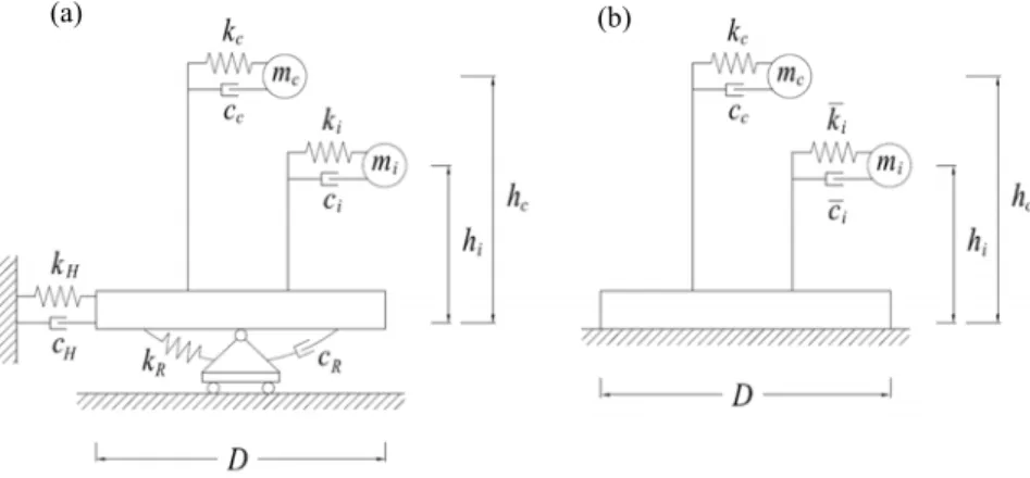
All the design codes use these analogues (which convert the tank-liquid system into an equivalent spring-mass system) to evaluate the seismic response of tanks. Figures 1.3.1.2 schematically demonstrate such mechanical models both for rigid and for flexible tanks. Various quantities associated with a mechanical model are: impulsive mass mi, convective mass mc,
Fig. 1.3.1.1: Liquid filled tank modeled by a generalized SDOF system (after [30]).
Chap. 1: Dynamics of tank-fluid systems
height of impulsive mass hi, height of convective mass hc, impulsive and convective time period Ti and Tc. It may be noted that heights hi and hc are used when base pressure is not considered. If base pressure is included, then the corresponding heights are denoted by hi’ and hc’ respectively. In this way, the global overturning moment above and below the base plate is different, see Figure 1.3.1.3. The one above the base plate is used to design the tank walls, whereas the one below the base plate is used to design the foundation (this is why it is also named “foundation moment”).
In Table 1.3.1.1 the most important contributions to the tank-liquid system modeling are reported in chronological order.
Fig. 1.3.1.2: (a) Mechanical model (a) for rigid tanks, (b) for flexible tanks.
(a) (b)
Chap. 1: Dynamics of tank-fluid systems
Table 1.3.1.1: Time history of the mechanical models currently availbale in literature.
Rigid tank models Flexible tank models
1963 Housner model for rigid circular and rectangular tanks [26].
1977 Veletsos and Yang model for circular rigid tanks [56].
1978 Wozniak and Mitchell generalized the Housner model.
1981 Haroun and Housner model for flexible tanks [22].
1984 Veletsos model for flexible tanks [47].
2000 Malhotra proposed a simplified version
of the Veletsos model [30].
Various codes adopt one or the other mechanical models described above. ACI 350.3 and API 650 use mechanical model of Housner (1963) with modifications of Wozniak and Mitchell (1978). It is interesting to note that API 650 deal with circular steel tanks, which are flexible tanks. However, since there is no appreciable difference in the parameters of mechanical models of rigid and flexible tank models (Figures 1.3.1.4), this code evaluate parameters of impulsive and convective modes from rigid tank models.
E
Eurocode 8 mentions mechanical model of Veletsos and Yang (1977) as an acceptable procedure for rigid circular tanks. For flexible circular tanks, models of Veletsos (1984) and Haroun and Housner (1981) are described along with the procedure of Malhotra et al. (2000).
(a) (c)
(b) (d)
Fig. 1.3.1.4: Rigid models (Veletsos, Wozniak) vs. Flexible models (Malhotra). Comparison of (a) impulsive and convective masses, (b) impulsive heights, (c) convective heights, (d) convective time period (after [28]).
Chap. 1: Dynamics of tank-fluid systems
1.3.2 Unanchored tanks – General remarks and mechanical models
In the case of unanchored tanks, the tank bottom edge is not fixed to the foundation. Many tanks currently in operation, especially with great dimensions, are unanchored, because concrete foundations, which are needed for the anchors and the anchors themselves are very expensive. Furthermore, because improperly detailed anchors can cause damage to the shell under seismic loading, it is common, particularly for large tanks, to support the tank wall on a ring-wall foundation without anchor bolts and the bottom plate to rest on a compacted soil (though sometimes the ring-wall is omitted). For such tanks, the overturning moment caused by the hydrodynamic pressure tends to lift the shell off the foundation as shown in Figure 1.3.2.1. As the shell displaces upward, it pulls against the tank bottom causing the bottom plate to pick up liquid to provide resistance to the upward shell movement. On the opposite side, high compressive stresses are developed which may cause buckling of the shell.
The dynamic behavior is quite different from that of anchored tanks. As a consequence of the overturning moment caused by the dynamically activated pressures due to earthquake, partial uplift of the boundary of the bottom plate is possible. This uplift of the bottom plate gives rise to the following phenomena:
a strongly nonlinear fluid-shell-soil interaction problem has to be considered;
the maximum axial membrane compression force in the tank wall increases significantly, and loss of stability may occur at lower overturning moments;
uplift of the bottom plate represents a stiffness loss of the whole fluid-shell system. The natural frequencies of the fluid-shell interaction vibration decrease. The corresponding mode shapes, the damping values and the dynamically activated pressures are changed;
Chap. 1: Dynamics of tank-fluid systems
the contribution to the dynamically activated loads due to sloshing may increase because of the decreased natural frequencies of the interaction vibration.
Few approximate methods are currently available to estimate the stress level at the shell bottom, and none are based on a rigorous treatment of this nonlinear problem. On the contrary, numerous sophisticated analyses have been carried out to investigate the dynamic response of anchored tanks. For such structures, vertical motion of the shell at the foundation level is prevented, and therefore, their seismic behavior can be analyzed by evaluating the natural modes of vibration (Figure 1.3.2.1) and superposing them properly. Field observations and studies of the performances of uplifting tanks during past earthquakes (Northridge earthquake, [6], and Imperial Valley earthquake, [19]) have revealed that such systems are prone to extensive damage due to:
buckling of the tank wall, caused by large compressive stresses;
rupture at the plate-shell junction, caused by excessive plastic yielding;
failure of the piping connections to the wall that are incapable of adsorbing large base uplifts.
Dynamic tests as well as static tilt tests have been performed to study the behavior of unanchored tanks. Much data are available on the phenomena, but only a limited amount of interpretations was given. One can conclude from the results that the response of unanchored tanks is dominated by the uplift mechanism. Wozniak and Mitchell (1978) published the first recommendations for design rules of unanchored tanks, taking into account the increased axial membrane force in the tank wall. The same procedure, adopted in the API 650 standard, is studied here in Section 2.3.2. Many authors concluded from their investigations that this procedure is not sufficiently accurate and gives conservative estimates for unanchored tanks only under specific conditions.
Past studies relevant to unanchored tanks can be divided into:
theoretical studies using static models, often combined with static tilt tests. The main purpose of such quasi-static investigations is to study the influence of uplift on the stresses in the tank;
theoretical studies which deal with the dynamic behavior of unanchored tanks. In these investigations dynamic nonlinear models have been proposed for calculating the amplitude dependent natural frequencies, mode shapes, and the dynamically activated pressures.
Chap. 1: Dynamics of tank-fluid systems
Static studies
As already said, one of the first static study was taken by Wozniak and Mitchell (1978). They presented a very simple uplift model in which the resistance to overturning moment is provided by a portion of the weight of the fluid content WL; and this depends on the width of a ring of the bottom plate that is lifted off the foundation. The calculation of this width is based on a small deflection theory of an elementary strip of the bottom plate which can be lifted off the ground with the assumption of two plastic hinges: one at the plate-shell junction and the other at some point on the uplifted part L, as shown in Figure 1.3.2.2. Using translational and rotational equilibrium one can calculate the uplifted length and the uplifting force (as the force which brings a beam to a kinematic mechanism with two plastic hinges in the sense of the limit load of the beam). For explicit calculations see Section 2.3.2. In this model the horizontal membrane force and the friction between bottom plate and soil were neglected.
A more sophisticated model to solve the contact problem of the partially uplifted base plate and its interaction with the cylindrical shell is solved by Peek and Jennings (1988) using the finite difference energy method and a Fourier decomposition of the displacements in the circumferential direction, [36]-[37]. Nonlinearities due to contact, finite displacements and yielding of the tank material were included in the analysis. Furthermore, a method of analysis is presented in which the tank is supported from below by a circular bed of nonlinear springs, representing the retaining action of the bottom force. According to the so called “shell-spring model” (Auli et al. (1985), [15]-[16]), the nonlinear springs characteristic may be calculated by applying analytical procedures or by the finite element method. For example, an axisymmetric finite element model can be used, taking into account geometrical and material nonlinearities. For every uplift force, the uplift height is determined. Scharf (1990) calculated the nonlinear springs characteristics for real liquid storage tanks. The results for three specific tanks are shown in Figure 1.3.2.3a and compared with the constant uplift force of Wozniak and Mitchell, which overestimates the retaining action of the bottom plate for lower uplift heights. Figure 1.3.2.3b
Fig. 1.3.2.2: Model for the uplifting force and uplifted length calculation.
Chap. 1: Dynamics of tank-fluid systems
shows the deformed shape of the tank bottom edge for different values of the uplift force. Especially in broad tank a third plastic hinge may develop at the thickness step of the bottom plate.
Dynamic studies
Since a strongly nonlinear (geometric and material) fluid-structure-soil interaction and contact problem has to be solved, the calculation of the dynamic response of unanchored tanks is very complicated. Hence, no fully satisfying models are available.
Two simplified nonlinear analytical models were developed by Natsiavas, (1987,1988,1989), taking into account separation of the bottom plate, soil flexibility and liquid sloshing effects, [32]. Results obtained by an application of these models were published by Natsiavas and Babcock (1988), [33]. They conclude that the hydrodynamic pressure of unanchored tanks is mainly caused by the rigid body translation and by the rigid body rotation due to uplift. There is practically no contribution from the shell flexibility. It should, however, be investigated if uncoupling of the rocking motion due to uplift and the motion due to shell flexibility is really realistic. Nevertheless, the investigations of Natsiavas give an excellent insight into the problems of estimating the dynamic response and failure mechanism of unanchored earthquake excited liquid storage tanks.
In [15]-[16] Scharf (1990) proposed a modified response spectrum method for estimating the maximum dynamic response of unanchored tanks. Similar to Natsiavas, the Housner model was modified. Instead of a contribution due to the common vibration of the shell and the liquid, a contribution due to the interaction vibration including the rocking motion due to uplift was assumed. The resulting contribution to the overturning moment is represented by a single-mass oscillator with a nonlinear spring characteristic. It can be shown that an equivalent period for the amplitude interaction vibration including the uplift motion in combination with an iteration
Fig. 1.3.2.3: Uplift force V vs uplift heigth w (after [16]).
(a)
Chap. 1: Dynamics of tank-fluid systems
procedure and displacement response spectra yields sufficiently accurate estimates for the maximum dynamic response.
As a consequence of the uplift motion of the bottom plate and additional contribution to the hydrodynamic pressure is activated. This contribution is taken into account in the models of Natsiavas and Scharf. The analytical solution of Scharf agrees well with that of Veletsos and Tang (1987), [50], who investigated a rocking rigid tank, but Scharf’s solution is more general.
Dynamical investigations of earthquake excited unanchored tanks can be performed by the finite element method. The advantage of using such a method is that the whole fluid-shell-foundation system can be modeled and various types of results, such as natural frequencies, mode shapes, the hydrodynamic pressure, the stresses in the shell and the stability loss, can be obtained. But the effort as well the requirements of CPU time and core memory increase dramatically if nonlinear effects such as yielding and partial uplift of the bottom plate are included in the analyses. That is why finite element models for dynamic analyses employ simplifications such as “the shell-spring model” (Auli et al. (1985), [15]-[16]).
All studies mentioned above allow the conclusion that there is a need for more research in the field of earthquake excited unanchored tanks to reach a deeper insight into this strongly nonlinear problem.
1.3.3 Fluid‐structure interaction
For design purposes, fluid-structure interaction is typically modeled using the simplified codes provisions. In this case the most common way to proceed is to carry out linear elastic analyses on a finite element model of the tank, in which the fluid is replaced by the hydrodynamic pressure distibution suggested by the codes. Then, the nonlinear behavior of the structure is taken into account by computing the elastic and elasto-plastic buckling stress and checking that they are not reached at any point of the finite element model. Examples of fluid-as-external-pressure modeling may be found in [39] and [42] by Wunderlich et al. In [39], a detailed numerical example of hydrodynamic pressure derivation can be found.
Chap. 1: Dynamics of tank-fluid systems
Since the simplified models adopted by the codes are often “too much simplified” because they are based on outdated assuptions and results, two different methods are currently used for research purposes. The first one is the so called “added mass method” and the second one directly involves “fluid finite elements”.
The “added mass method” was first developed by Westergaard (1933) in a study on the dynamic interaction between a dam and a reservoir system, Figure 1.3.3.3. According to Westergaard, the hydrodynamic pressures that the water exerts on the dam during an earthquake are the same as if a certain body of water moves back and forth with the dam while the remainder of the reservoir is left inactive. The dam was initially considered as rigid by Wetergaard. Then, the dynamic interaction between the retained water and a flexible dam was studied by Lee and Tsai using modal superposition analysis. They considered the dam as an Euler-Bernoulli beam and showed that the added mass, which vibrates together with the structure during the imposed excitation, results from the hydrodynamic effect due to the current deflection of the structure and the current response of the entire system. It is a function of the mode shapes of both the structure and the reservoir. So, in case of a flexible dam, the added mass is varying during the dynamic analysis.
Examples of the “added mass method” application to tank-liquid systems can be found in [52]-[53]-[54] by Virella et al. Here, the idea is that the inertia of that portion of the fluid which acts impulsively is somehow lumped in with the inertia of the tank walls. The added masses are calculated from pressure distributions of rigid tanks and they do not vary during the dynamic analysis. This assumption is not strictly correct; in fact, in the light of what shown by Lee and
Fig. 1.3.3.2: Hydrodynamic pressure due to vertical shaking (after [39]).
Chap. 1: Dynamics of tank-fluid systems
Tsai, for flexible structures the added mass depend on the flexibility of the structure itself. In case of tank-liquid systems, studies by Veletsos and Yang (1977) and Haroun and Housner (1981) showed that the pressure distribution due to the liquid impulsive component in rigid and flexible tanks were similar, especially for broad tank (H/R<1), Figure 1.3.3.4. However, the magnitude was highly dependent on the flexibility of the tank wall.
As a conclusion, the “added mass method” which employs masses that do not vary during the analysis is particularly correct for broad tank. From a practical point of view, the added mass approach essentially consists in deriving liquid masses from pressure distributions and to attach them to the shell nodes of a finite element model, by means of massless rigid elements, as shown in Figures 1.3.3.5.
Fig. 1.3.3.5: Model with added masses around the circumference and along the height (after [53]).
Fig. 1.3.3.4: Pressure distribution along the tank height (a) for rigid and (b) for the 1st mode of flexible tanks (after [48]).
Chap. 1: Dynamics of tank-fluid systems
Because the added masses are determined from the impulsive pressure which is normal to the shell surface, they must be added in such a way that they only add inertia in this direction. For this reason, the added masses are sometimes referred to as the “normal masses”. The one-direction elements have supports oriented in their local axes that constrained the motion of the nodal masses to the normal direction of the shell. The motions of each support are restricted in the global tangential direction (i.e. perpendicular to the element axis) and in the vertical direction, whereas it is free to move in the radial direction (i.e. local axial direction of the rigid element). To obtain the lumped mass mi at each node, the height of the cylinder is divided into several segments. For a radial section of the tank, the lumped mass mi at each location is computed using the rectangular rule. For an interior node at the tank shell:
∆
(1.3.3.1a) where pi is the pressure at node i, ∆h is the constant distance between nodes and an is the reference normal acceleration (an=x for ϑ=0). For nodes at the liquid surface and at the bottom of the tank:
2 ∆
(1.3.3.1b) As already mentioned, the “added mass method” with masses derived from the rigid impulsive pressure is not really accurate for slender tanks, in which the pressure distribution is quite different depending on whether the tank is considered rigid or flexible, and also modes higher than the first play a significant role. For slender tank, the added mass are really varying during the dynamic analysis. Furthermore, previous works suggest that the added mass techniques should give reasonably accurate predictions for a rigidly anchored tank. However, it is not clear how successful such an approach would be for the case where the tank base can separate from the floor.
Due to these limitations, as an alternative to the above metioned method, a very recent technique is to model the liquid by directly using “fluid finite elements”. With such a method we are totally released from the codes provisions and spring-mass models, thus studying the problem into a “global finite element framework”. A class of elements is available in ANSYS and ABAQUS which are specially formulated to model fluids contained within vessels having no yet flow rate. These elements are displacement-based, which makes them easier to integrate into a general finite element structural analysis program than the alternative formulation in which the
Chap. 1: Dynamics of tank-fluid systems
pressure is the variable in the fluid. Numerical models which make use of fluid finite elements may be found in [4]-[5]-[10]-[54] by Di Carluccio, Fabbrocino et al.
For example, in [4] the behavior of the liquid fuel oil is represented by the Lagrangian approach. In this approach, fuel oil is assumed to be linearly elastic, inviscid and irrotational. The formulation of the fluid system based on Lagrangian approach is given in literature. The determination of the interface condition is required to obtain the coupled equations of the storage tank-liquid fuel oil system. Because the fuel oil is assumed to be inviscid, only the displacement in the normal direction is continuous at the interface of the system. Lengths of coupling elements as 0.001m are used to supply fluid-structure interaction between liquid fuel oil and storage tank interface. The main objective of the couplings is to hold equal the displacements between two reciprocal nodes in normal direction to the interface.
1.3.4 Soil‐structure interaction
The flexibility of the supporting medium, like that of the tank wall itself, may be considered to affect only the impulsive effects. Accordingly, the convective components of the response, like those for rigidly supported flexible tanks, may be evaluated with reasonable accuracy considering both the tank and the supporting medium to be rigid, because it is associated with actions of significantly lower frequencies than the natural frequencies of the
Chap. 1: Dynamics of tank-fluid systems
tank-liquid system or the dominant frequencies of the excitation. Therefore, the following discussion deals exclusively with the impulsive effects.
For a specified free-field ground motion, the impulsive component of the response of a flexibly supported tank may differ significantly from that of the same tank when rigidly supported. Two factors are responsible for this difference:
the flexibly supported system has more degrees of freedom and, therefore, different response characteristics from those of the rigidly supported system. In particular, whereas the foundation motion of the rigidly supported system is the same as the free-field ground motion, the corresponding motion of the flexibly supported system, because of its interaction or coupling with the supporting medium, may be significantly different, and will generally include a rocking component even for a purely horizontal free-field motion. The rocking component may be particularly prominent for tall tanks and very flexible soil;
part of the vibrational energy of the elastically supported system may be dissipated into the supporting medium by radiation of waves and by hysteretic action in the soil itself. There is, of course, no counterpart of these forms of energy dissipation for a rigidly supported system.
Based on available solutions for rigidly supported tanks and of elastically supported structures of the building type, it was estimate that the single-degree-of-freedom approximation would probably be quite adequate for relatively broad tank with H/R of the order of 1.5 or less, but might lead to non-conservative results for tall, slender tanks.
In addition to the parameters enumerated previously (Section 1.3.1) for rigidly supported systems, the response of a flexibly supported tank depends on:
the stiffness of the supporting soil, specified by the velocity of shear wave propagation in the soil, v G ρ⁄ ;
Poisson’s ratio of the soil νs and the associated damping factor ξs; radius and mass of the foundation, R0 and m0.
Two factors complicate the analysis of elastically supported systems:
system damping is of a form for which the classical modal superposition method of analysis is not applicable;
the resistances of the foundation, the so called foundation impedances, are frequency-dependent quantities.
Chap. 1: Dynamics of tank-fluid systems
The analysis can, however, effectively be implemented in the frequency domain making use of the discrete Fourier transform (DFT) technique in combination with the fast Fourier transform (FFT) algorithm. Apart from the exact method, not covered by the present work, several simpler, approximate procedures have been used to evaluate the response of the flexibly supported tank-liquid system and to assess the effects of soil-structure interaction (SSI). In the most accurate of this approaches, by Veletsos and Tang [49], the tank-liquid system in its fixed-base condition is treated as a multi-degrees-of-freedom system, but SSI is considered to affect the contribution of the fundamental impulsive mode of vibration only. The contributions of the higher modes in this approach are evaluated approximately by considering the tank to be rigidly supported at the base. Additionally, the interaction effects for the fundamental mode of vibration are accounted for indirectly by modifying the natural frequency and damping of that mode and evaluating its response to the prescribed free-field ground motion considering the tank to be rigidly supported at the base. For the justification of this approach and for the procedure used to arrive at the modified natural frequency and damping, the reader is referred to [49].
Provisions for consideration of SSI are provided only in NZSEE guidelines and Eurocode 8. First provision pertains to influence of soil flexibility on time period of tank. Expressions for time period of lateral and vertical mode of tank, including the effect of soil flexibility are provided. These expressions are taken from Veletsos (1984). Secondly, inclusion of soil also increases the damping of the structure. Expressions are also provided for equivalent damping of tank-fluid-soil system. In EC8, to investigate the influence of the foundation flexibility on the seismic response of tanks the mechanical model developed by Veletsos and Tang (1992) is used.
1.4 Draft conclusions and research needs
Although these design provisions represent a significant advance in the design of tanks, observations in recent earthquakes and experimental studies seem to indicate that they may not be adequate to accurately predict the seismic response of cylindrical tanks. It must be noted that in perfect circular cylindrical tanks, the cos nϑ-type modes cannot be excited by rigid base motion; however, fabrication tolerances in civil engineering tanks permit a departure from a nominal circular cross section and this tends to excite these modes. Little can be found in literature about the importance of the cos nϑ-type modes in an earthquake response analysis. This is probably due to the fact that the magnitude and distribution of fabrication errors cannot be predicted, and consequently, only hypothetical analyses can be made.

![Fig. 2.4.1.2: Dynamic coefficients for the 1 st mode of the impulsive horizontal vibration of the equivalent system with flexible foundation (after [17])](https://thumb-eu.123doks.com/thumbv2/123dokorg/7483887.103226/90.892.199.675.438.669/dynamic-coefficients-impulsive-horizontal-vibration-equivalent-flexible-foundation.webp)
![Fig. 2.4.3.1: Types of ground-supported, liquid-containing structures classified on the basis of their wall-to-footing connection (after [1])](https://thumb-eu.123doks.com/thumbv2/123dokorg/7483887.103226/92.892.175.699.189.668/types-ground-supported-containing-structures-classified-footing-connection.webp)
![Fig. 2.5.6.1: Maximum pressure at the tank bottom due to horizontal and vertical excitation (after [15]).](https://thumb-eu.123doks.com/thumbv2/123dokorg/7483887.103226/105.892.392.774.577.839/fig-maximum-pressure-tank-horizontal-vertical-excitation.webp)

![Fig. 3.2.4.1: Elastic and elasto-plastic buckling strengths of anchored steel cylindrical tanks (after [18])](https://thumb-eu.123doks.com/thumbv2/123dokorg/7483887.103226/133.892.184.730.471.813/elastic-elasto-plastic-buckling-strengths-anchored-steel-cylindrical.webp)