6
Drilling Polymeric Matrix Composites
Edoardo Capello1, Antonio Langella2, Luigi Nele2, Alfonso Paoletti3, Loredana Santo4, Vincenzo Tagliaferri4
1Dipartimento di Meccanica, Politecnico di Milano, piazza Leonardo da Vinci 32, 20133 Milano, Italy.
E-mail: [email protected]
2Department of Materials and Engineering Production, University of Naples Fede-rico II, Piazzale Tecchio 32, 80125 Napoli, Italy.
E-mail: [email protected], [email protected]
3Università di L’Aquila, Piazza V. Rivera 1, 67100 L’Aquila, Italy. E-mail: [email protected]
4Dipartimento di Ingegneria Meccanica, Università di Roma “Tor Vergata”, via del Politecnico 1, 00133 Roma, Italy.
E-mail: [email protected], [email protected]
This chapter presents the basics of drilling of polymeric matrix composites (PMCs). PMCs are becoming widely used in the manufacturing of products where a high mechanical strength must be accompanied by a low weight. However, the machining of PMCs implies coping with problems that are not encountered when machining other materials. Drilling is a particularly critical operation for PMCs laminates because the large concentrated forces generated can lead to widespread damage. This damage causes aesthetic problems but, more importantly, may com-promise the mechanical properties of the finished part.
6.1 Introduction
6.1.1 What Are Polymeric Matrix Composites?
Composite materials are made up of two or more constituents [1–8]. The principle behind the study of composite materials and their applications is based on the possibility of using materials with specific characteristics which, when joined together in an appropriate manner, create a single composite material with final properties that are not found in any of the raw materials.
One of the constituents, called the matrix, usually determines the characteristics of the composite material primarily according to the field of application, the tem-perature of use and the weight. Its role is to contain another constituent, called the
reinforcement, which determines the principal mechanical characteristics of the
composite material, tensile modulus and mechanical resistance.
In nature, it is possible to find various examples of natural composite materials, such as bone or wood. An artificial composite material can be obtained using various types of matrix and with various types of reinforcement. The reinforce-ment may be in the form of filareinforce-ments, called fibres (long or short), or in the form of particles. In theory, all materials can be used for the production of fibres, but in practice only a limited number of materials can be selected, and even fewer of these have those mechanical characteristics that are of interest in engineering ap-plications.
Both matrix and fibres can be metallic, ceramic or polymeric, and the compos-ite materials, classified according to matrix type, can be divided as follows:
• polymeric composites • metallic composites • ceramic composites
Polymeric matrix composite materials (PMCs) have a matrix which is made of a thermoset or a thermoplastic polymeric resin. Polymeric matrices are made up of rigid polymeric chains obtained from liquid monomers by means of a process of chemical transformation known as polymerization.
Thermoplastic matrices are polymers that have polymeric chains without trans-verse bonds and thus, after polymerization, an increase in temperature leads to a reduction in viscosity and to a melting of the matrix. The melting from a solid state develops through a gummy state, in a manner which is reversible.
Thermoset matrices are, on the other hand, characterized by the presence of strong transverse bonds which are created during polymerization, and which make the process not reversible. Indeed, an increase in temperature after polymerization does not initially generate substantial variations in the matrix properties, while beyond a certain limit it causes the total degradation of the matrix.
With the use of thermoplastic matrices, the component manufacturer uses a semi-finished product in which the polymerization reactions have already taken place and are guaranteed by the producer of the matrix. These semi-finished prod-ucts need only to be modelled to obtain the required shape for the final compo-nent. As opposed to thermoset matrices, the application of thermoplastic matrices in composite materials has, in the past, been hindered by a low softening tempera-ture, a lower tensile modulus and by reduced adhesion between fibres and matrix. Some types of thermoplastic matrices with properties similar to those of thermoset matrices are currently available, but with the prospect of lower transformation costs. The main thermoplastic matrices used in polymeric composite materials are: ether-ketones (PEEKs), poly-phenylene-sulphide (PPS), and poly-ether-imide (PEI).
With the use of thermoset matrices, the polymerization process must be carried out during the manufacturing cycle of the component, and this requires a rigid, more careful control of the process. The fact that thermoset matrices are so widely used is due to their strong mechanical properties and to the low cost of the matri-ces. Moreover, manual and semi-manual processing can be easily performed.
The most commonly used types of resin are polyester and epoxy. Unsaturated polyester resins have good mechanical characteristics, are easily workable and polymerize at room temperature. Unsaturated polyester resins can be classified according to the constitutional groups that appear in the chain structure. Among the most common are the ortophtalic polyesters, the isophtalics, the bisphenols and the dicyclopentadienyls.
Bicomponent or monocomponent epoxy resins have better mechanical proper-ties compared to polyester resins, although they have a higher cost. Consequently, their application is generally limited to advanced applications in the aerospace industry.
The most commonly used types of reinforcement are glass, carbon and ara-midic fibres.
The most common commercial formats of reinforcements for polymeric matrix composites are:
• Mat: The fibres are arranged on a plane in a random manner and are lightly compressed and treated with an adhesive. Alternatively, the unifilo mat can be used, in which a single thread is arranged on a plane in a casual manner. The mats are used to create quasi-isotropic composites with mod-erate mechanical characteristics;
• Roving: Long fibres are wound around bobbins, from which they are un-wound in bundles and used as continuous fibres or cut to obtain short fi-bres;
• Woven – fabric: Continuous long fibres are braided together to form a bi-dimensional or tribi-dimensional material;
• Pre-pregs: These are semi-finished products widely used in advanced ap-plications, in which fibres have been impregnated with the right amount of thermoset resin and kept at low temperature, away from the light.
The processes used in the manufacture of polymeric composite materials allow the fibre and matrix volumes to be selected in such a way that particular requirements can be met. The quantity of fibres present usually reaches 60% of the available volume, while the matrix occupies the remaining 40%. The properties of the com-posite material obviously depend on the properties of the reinforcement and the matrix (Tables 6.1 and 6.2), and on the quantity of these.
A simple rule to predict in a first approximation a property of the composite is the so-called mixture rule which states that:
= ⋅ + ⋅
c f f m m
P P V P V (6.1)
in which Pc is the resulting property of the composite to be determined, Pm and Pf
are the properties of the matrix and the reinforcement and Vm and Vf are the
volu-metric fractions of the matrix and reinforcement present, respectively.
The reinforcement and the matrix are arranged on a plane, forming a so-called
lamina in which the fibres (short or continuous) are suspended in the matrix
(Fig-ure 6.1). The fibres may be placed casually or they may be aligned. The study of interaction between fibres and matrix is known as micromechanics.
Table 6.1. Properties of matrices commonly used from polymeric composite materials Matrix material Tensile modulus (E) (GPa) Tensile strength (σu) (GPa) Density (ρ) (g/cm3) Ultimate elongation (%) Epoxy 2.75–4.10 55–130 1.2–1.3 4–8 Polyester 2.80–3.50 20–80 1.1–1.4 1,4–4,0 PEEK 3.2 100 130–1.32 50 PPS 3.3 83 1.36 4 PEI 3 105 1.27 60
Table 6.2. Properties of fibres commonly used from polymeric composite materials
Fibre material Tensile modulus (E) (GPa) Tensile strength (σu) (GPa) Density (ρ) (g/cm3) Ultimate elongation (%) Glass E 80 – 81 3.1–3.8 2.62 4.6 Glass S 88– 91 4.4–4.6 2,48 5.4–5.8
Carbon, low modulus * 170–241 1.4–3.1 1.90 0.9 Carbon, high modulus * 380–620 1.9–2.8 2.00 0.5
Aramidic (Kevlar 29) 83 3.6 1.44 4.0
Aramidic (Kevlar 49) 131 3.6–4.1 1.44 2.8 * Mesophase pitch-based carbon fibre
A lamina is assumed to behave orthotropically. The overlapping of several laminae with various fibre orientations makes up a laminate (Figure 6.2). The sequence of fibre orientations in the various laminae must be precisely defined as it influences the mechanical behaviour.
In fact, the overlapping of several orthotropic laminae can create a laminate with orthotropic or anisotropic behaviour, depending on the various orientations and the different positions within the thickness of the laminate. The study of the behaviour of laminates is known as macromechanics.
Figure 6.2. Overlapping of several laminae to form a laminate
Table 6.3. Properties of conventional structural materials and fibre composites with fibre
volume fraction of 60% Material Tensile modulus (E) (GPa) Tensile strength (σu) (GPa) Density (ρ) (g/cm3) Specific Modulus (E/ρ) Specific strength (σu/ρ) Ultimate elonga-tion (%) Mild steel 210 0.45–0.83 7.8 26.9 0.058– 0.106 38–50 Aluminium 70 0.26–0.41 2.7 25.5–27.0 0.096– 0.152 30–40 E-Glass epoxy 21.5 0.57 1.97 10.9 0.26 2.5 E-Glass polyester 22.1 0.38 1.61 13.7 0,23 3.4 Kevlar 49–epoxy 40 0.65 1.4 29.0 0.46 1.8 Carbon fibre–epoxy 90 0.38 1.54 58.4 0.25 1.0
6.1.2 The Importance of Drilling
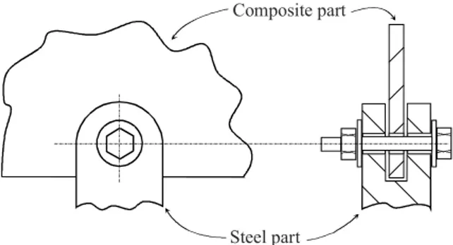
In most cases a composite part needs to be assembled to other parts, either in posite or in a different material (steel, aluminium alloys, wood, etc.). Since com-posite materials cannot be welded, and glueing is quite complex (and cannot be disassembled), mechanical joining (rods, pins, fasteners, rivets, etc.) is the solution commonly adopted to assemble a composite part to other parts (Figure 6.3).
The holes required by mechanical joining are generally drilled in the semi-finished composite part. This procedure is generally preferred to the one where a core is placed in the mould during the curing phase. Only large-diameter or com-plex contour holes are manufactured using this technique.
Since a composite part should perfectly match with the other parts during the assembly phase, holes must be placed in the exact position required, and must have the correct diameter. Moreover, due to their load transfer commitment once in use, holes generally undergo intense localised stress. Consequently, holes are generally subjected to specifications both in geometrical and mechanical terms.
Geometric specifications are the same as the usual given on holes drilled in other materials. They generally consist of specifications on dimension (diameter), position (of the hole centre) and shape (roundness, cylindricity and straightness). Microgeometry (i.e., roughness) con be subject to a specification too, and is gen-erally given in terms of the roughness of the cylindrical surface of the hole. Roughness, cylindricity and straightness specifications are seldom used on thin composite laminates. All these specifications must be reported on the mechanical drawings following the active ISO standards.
The mechanical properties that the material presents around the drilled hole are generally different from (i.e., lower than) the ones that can be found far from the hole. This is because drilling is an invasive process and the material around the hole undergoes structural damage that will be described later. The term residual
mechanical properties is generally used to describe the mechanical properties that
the material around the hole presents after the drilling process.
The residual mechanical properties strongly depend on how the hole has been drilled. Abusive parameters can deeply damage the material around the hole, thereby leading to limited residual mechanical properties and a hole that cannot withstand the required mechanical load and will fail once in use.
Mechanical specifications are more seldom used in composite manufacturing, and no standards exist for their expression on mechanical drawings. Generally speaking, the material around a hole must withstand a sufficient static load and have an adequate fatigue limit. These characteristics must be present both at the end of the manufacturing phase and during the whole life of the part.
To summarise, it can be stated that drilling conditions and parameters strongly influence the quality of the drilling process from both the mechanical and geomet-rical point of view. Poor hole quality was estimated to cause 60% of composite part rejection during quality control in the composite manufacturing industry. This rejection is particularly severe from the economic point of view since it occurs in the last phases of production when the manufacturing cost of the composite part has already been faced.
Consequently, a carefully designed drilling process is the first step to obtaining an economic composite part that can be assembled and is fail safe.
Composite part
Steel part
6.2 Drilling Technology of Polymeric Matrix Composites
6.2.1 Conventional Drilling Process
6.2.1.1 The Twist Drill
The most commonly used tool in the conventional drilling of composite materials is the twist drill (Figure 6.4), generally obtained in high-speed steel (HSS). The twist drill [19–21] is made up of a cylindrical shank into which two opposite heli-cal grooves have been cut, forming two cutting lips at the end surface (AB and CE). A central chisel edge (AC) is present near the drill axis to connect the two cutting lips.
The flank (α) and rake (γ) angles (described in Chapter 2) play an important role in PMCs drilling, as they influence the hole quality.
In fact in drilling the angles αf and γf observed in the feed plane of the tool-in-hand reference system (Figure 2.4) may differ substantially from the ones (α and
γ) observed in the tool-in-use reference system.
Considering Figure 6.5, it can be observed that a generic point on the cutting lip rotates with a tangential speed of vt [m/s]:
2 60 1000 π ω = ⋅ = ⋅ ⋅ t v r n r (6.2)
where ω [rad/s] is the rotation velocity, n is the revolution per minute [rpm] and r [mm] is the distance of the considered point from the drill axis. Therefore, it can be observed that in drilling the cutting speed varies along the cutting lip: it is at its maximum value on the periphery of the drill and decreases to zero on the axis.
α vt A A A-A vA αf γ γf
Figure 6.5. Relief and rake angles of a twist drill cutting lip
The same lip point is fed along the drill axis at a speed vA [m/min] given by:
1 60 1000 = ⋅ ⋅ A v f n (6.2)
where f [mm/rev] is the feed rate.
It can be easily observed that that the in-use angles are related to the tool-in-hand feed rate plane angles through the following relationship (Figure 6.5):
2 γ γ= + ⎜⎛ ⎞⎟=γ + ⎛⎜⎝ π ⎞⎟⎠ ⎝ ⎠ A f f t v f tan tan v r (6.3) 2 α α α π ⎞ ⎛ ⎛ ⎞ = f − ⎜⎝ A⎟⎠= f − ⎜⎝ ⎟⎠ t v f tan tan v r (6.4)
As the considered point on the cutting lip is moved closer to the drill axis, r be-comes small, and special care must be given to avoid negative values of the flank angle α: If the flank angle becomes negative there is no longer a cutting action by the lips but the twist drill acts like a punch. In PMCs drilling with punching action is particularly dangerous as it leads to the damage of the material, which dramati-cally reduces the structural integrity of the material around the hole.
Negative values are generally avoided by adopting a proper tool geometry (αf increases from the periphery to the axis while γf decreases) and by selecting low feed rates.
6.2.1.2 Wear of the Twist Drill
One of the main limitations when drilling PMCs with the conventional HSS twist drill is the excessive wear experienced by the tool. In fact, while a HSS twist drill can be used to drill hundreds of holes in carbon steel before being worn out, in PMCs drilling the same drill may last for fewer than ten holes.
This rapid wear is due to the abrasive nature of the reinforcement fibres, and is present regardless of the shape or length of the fibres. The wear generally in-creases with the fibre volume fraction and hardness.
Tool wear has a significant effect on hole damage as the thrust force increases as tool wear proceeds.
6.2.1.3 Thrust Force
During drilling, a vertical force, that is, a thrust force, is generated. This thrust force can be considered as the sum of several components, each one rising either from the cutting process or from the friction between material and cutting tool (Figure 6.6).
The cutting process occurs along the cutting lips and at the chisel edge. The cutting process along the lips generates a force on each lip that has a component
Fcl,A parallel to the axis of the drill, that is, the feed direction. Moreover, the chisel edge generates a vertical penetration force, called Fce.
The friction forces arise from two components. The first is related to the fric-tion between the side surface of the tool and the generated hole surface, which leads to the vertical force Fss. The second component is related to the friction
between the chip flow along the helical grooves, which generates the vertical force Fhg.
The total axial thrust force acting on the drill is therefore: 2
= + + +
A cl ,A ce ss hg
F F F F F (6.5)
as Fcl,A is generated on both cutting lips.
The thrust force observed during drilling not only depends on the geometry of the drill and on the type of material and laminate being worked upon, but also on the relationship between the feed rate and the cutting speed, as well as on the de-gree of wear of the drill [22–24].
In Figure 6.7 a qualitative trend of thrust force FA as a function of the drilling
time t is shown. As can be seen, most of the time the thrust force is positive, that is, a pushing action is exerted by the drill on the workpiece. In the first period the thrust force continues to increase as an increasing part of the cutting lips is en-gaged in the material; in the second phase the thrust force remains at an almost
Fcl,A Fce Fcl,A Fhg Fss Fcl,N Fcl,N
constant value as the drill sinks into the workpiece. In the third phase the thrust force rapidly decreases when the twist drill exits, sometimes causing a negative thrust force, that is, a pulling force.
The actual level of the force depends on the material being drilled, on tool ge-ometry, material and wear, and on process parameters. An experimental measure of the thrust force as a function of feed rate is reported in Figure 6.8 [25, 26].
t FA
Figure 6.7. General trend of the thrust force as a function of drilling time
Figure 6.8. Experimental trend of the thrust force as a function of drilling time and feed
6.2.1.4 Torque
During drilling also a torque T is generated, once again being due to the cutting process and to friction.
The cutting torque is due to the horizontal component Fcl,N (normal to the
cut-ting lip, see Figure 6.6) of the cutcut-ting force. This force is applied somewhere along the cutting lip; as a first approximation it can be supposed to be applied at half the radius. Therefore, the cutting torque is:
2 2
= = ⋅
c r cl ,N cl ,N
T F r F (6.6)
The frictional torques are due to the torque generated by the friction between the chisel edge and the workpiece (Tce), the friction between the side surface of the
drill and the inside hole surface (Tss) and to the friction of the chip flow along the
two helical grooves (Thg).
The total torque value is:
= +c ce+ ss+ hg
T T T T T (6.7)
A typical trend of torque as a function of drilling time is shown in Figure 6.9. As can be seen, the torque initially increases rapidly in a linear manner up to the value Ti [25, 26]. This is due to the fact that an increasing part of the cutting
lips is involved in the process This is the part of the torque which is effectively due to the cutting operation.
Subsequently, a further but less steep linear increase in torque can be noted up to value Tmax. This increase is mainly due to the torque which is generated by friction between the lateral surface of the drill and the inside surface of the hole.
In the final phase of the process, when the drill breaks through the lower sur-face of the workpiece, the only remaining torque is related to friction between the
lateral surface of the drill and the inside surface of the hole. Consequently, the torque decreases to a value of Tm and remains constant.
As for the thrust force, the actual torque depends on the material being drilled, on several process parameters, on the tool shape, material and wear, and on the fixture system. A torque measurement obtained at different feed levels is reported in Figure 6.10.
6.2.2 Unconventional Drilling Processes
The main unconventional processes that can be used in composite drilling are laser cutting, water jet (WJ) cutting and abrasive water jet (AWJ) cutting.
In laser cutting, CO2 and Nd:YAG resonators are generally used (at wave-lengths of 10.6 μm and 1.064 μm, respectively), even though the CO2 resonators are far more frequently applied, as the 10.6 μm wavelength is very well absorbed by polymer-based materials. Typical power ranges from 50 W to 1 kW. The gen-erated laser beam is focussed on the surface with a spot of about 0.2 mm diameter, therefore yielding a power density (power per unit of exposed surface) as high as 102–104 W/cm2. This power density very rapidly heats the exposed material, which generally vaporises in less than ten milliseconds. Therefore, laser cutting is basically a thermal process.
If the diameter of the hole to be drilled is small (say from 0.1 mm up to 2 mm), the process can be performed without relative movement between the beam and the workpiece. For larger hole diameters a hole is first pierced in the material and then the beam contours the circular profile of the hole. This is actually a cutting action of the beam.
Although interesting for the absence of contact between tool and workpiece, which leads to the absence of cutting forces or tool wear, laser cutting presents some drawbacks that must be carefully considered.
Figure 6.10. Experimental measure of torque during drilling as a function of drilling time
The main limit of laser processing is that the maximum thickness that can be cut with reasonable quality is about 5–10 mm. Above this thickness an evident taper can be observed. Moreover, since laser cutting is a thermal process, thermal damage can be experienced around the drilled hole. Furthermore, since composites are actually made of two different materials that present different thermal proper-ties (matrix and reinforcement), poor hole quality can be generally observed.
In WJ cutting a highly pressurized jet (up to 500 MPa) is formed through a sapphire orifice (diameter 0.05–0.3 mm) and can travel at close to twice the speed of sound in air (about 500 m/s). The formed jet directly impinges on the composite surface and removes material through a set of complex physical mech-anisms, where cavitation plays the main role.
The hole pierced by WJ cutting is generally too small for many mechanical fas-teners, as the diameter of the hole is the same size as the orifice diameter. There-fore, holes are generally machined using a contour technique.
The main advantages of WJ cutting derive from the absence of tool wear and from the very limited force exerted by the jet on the workpiece. On the other hand, some delamination may occur, especially when piercing a composite laminate.
AWJ is similar to WJ, but the water jet is mixed with a flow of natural or syn-thetic abrasive particles (mass flow rate 100–800 g/min). The abrasive particles are then accelerated inside a carbide nozzle (diameter about 1 mm) by the water jet, and the speed of the particles is believed to reach a speed slightly below the speed of sound (about 250 m/s). The result is a jet of water and abrasive particles that can cut the composite through an erosion mechanism (it can actually cut al-most any material, ranging, for example, from steel to concrete).
The maximum thickness that can be drilled and cut can be much higher than in laser or in WJ cutting (up to say 200 mm) and very limited delamination is ob-served even in piercing.
Apart from drilling, these energy beam processes can also be used to trim the composite contour after curing or to cut slots in the manufactured part (such as, the visor window in a composite motorcycle helmet).
6.3 Modelling of Conventional Drilling
6.3.1 The Need for Modelling
As will be discussed later, several types of damages that can be observed in com-posite drilling can be directly related to cutting force and torque. In particular, delamination can be related to the thrust force during drilling. Therefore, it is par-ticularly important to model the cutting action and to derive an analytical model that predicts the thrust force as a function of process parameters.
The cutting action of a twist drill is a complex process of oblique three-dimensional cutting. The cutting speed and the rake and relief angles vary with the radial distance ρ along the cutting lips of the drill, therefore the process conditions vary noticeably along the cutting lips.
6.3.2 Cutting Force Modelling
Many studies are available in literature dealing with the modelling of the metal drilling process, and reference to Merchant’s shear plane model [9] is present in all of them. Unfortunately, all models developed for metals have proved to be unsuitable for composites, as the cutting mechanism is different [10–15]. Conse-quently, a tailored set of model for drilling PMCs had to be developed.
Since it was experimentally observed that 2Fcl ,A >Fce>>F ; Fss hg, only the
ac-tion of the cutting lips and of the chisel edge is generally considered in modelling, and the other two forces are neglected.
Since the cutting process varies along the cutting lip, each cutting lip can be de-scribed as being composed of several infinitesimal elements aside one other. On each element a orthogonal cutting process occurs, which is characterised by dif-ferent process parameters and difdif-ferent forces.
The cutting force per unit of lip length generated in the orthogonal cutting of composite materials can be divided into two components, one parallel to the cutting velocity (δFvt), the other (δFvn) perpendicular to it (Figure 6.11). These
two components can be predicted using the following experimental relationships [16–18]: 0 5 1 10 γ δ = ⋅ −a ⋅ . vn F B t (6.8) 1 10 γ δ = + ⋅ −b ⋅ vt F A B t (6.9)
where t1 is the thickness of the uncut chip and A, B, a and b are four experimental coefficients that mainly depend on the machined material.
The Fcl,N force, acting normal to the cutting lip, and the Fcl,A force, acting
paral-lel to the twist drill axis, can be obtained by adding together the contributions of the unitary forces δFvt and δFvt, using an integration operation along the whole
cutting lip [15,16] (Figure 6.12):
1 2 2 2 2 1 2 2 0 5 2 2 2 2 1 2 2 2 2 10 2 1 2 2 A vn a . w sin ( / ) F F R sin( / )d R w sin ( / ) B ( f / ) R sin( / )d R τ γ τ ε δ ε ρ ρ ε ε ρ ρ − ⎞ ⎛ = ⋅ ⎜ − ⎟ ⎝ ⎠ ⎞ ⎛ = ⋅ ⋅ ⎜ − ⎟ ⎝ ⎠
∫
∫
(6.10) 1 2 2 2 2 2 1 2 2 2 2 2 2 2 1 2 2 2 10 2 1 2 vt b w sin ( / ) T F R d R w sin ( / ) [ A B ( f / )] R d R τ γ τ ε δ ρ ρ ρ ε ρ ρ ρ − ⎞ ⎛ = ⋅ ⎜ − ⎟ ⎝ ⎠ ⎞ ⎛ = ⋅ + ⋅ ⎜ − ⎟ ⎝ ⎠∫
∫
(6.11)where the integration variable is ρ = r/R and the integration limits can be obtained from Figure 6.13.
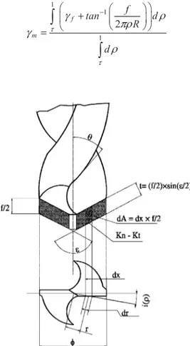
The actual rake angle, γ, is given by the sum of two addends as described by Equation (6.3). Since the closed analytical solution of Equations (6.10) and (6.11) is too complex, it is possible to adopt an average rake angle, γm, expressed as:
1 1 1 2 τ τ γ ρ πρ γ ρ − ⎛ ⎛ ⎞⎞ + ⎜ ⎜ ⎟⎟ ⎝ ⎠ ⎝ ⎠ =
∫
∫
f m f tan d R d (6.12)Figure 6.12. Twist drill and relevant parameters
vt
δFvt δFvn
Thus, the following quantities con be determined: 1 2 2 2 2 2 2 2 2 2 1 1 1 2 2 2 τ ε ρ ρ τ ε τ ρ ⎡ ⎤ ⎡ ⎛ ⎞ ⎤ = ⎢ − ⎥ = ⎢ − + ⎜ ⎟⎝ ⎠ ⎥ ⎣ ⎦ ⎣ ⎦
∫
w sin ( / ) G R d ( )R w sin ln R (6.13) 2 2 1 2 2 2 1 2 2 2 2 1 2 2 2 τ ε τ τ ε ε ε ρ τ ρ ⎡ ⎤ ⎞ ⎞ ⎛ − − ⎛ ⎜ ⎟ ⎢ ⎜ ⎟⎥ ⎡ ⎤ ⎝ ⎠ ⎣ ⎝ ⎠⎦ = ⎢ − ⎥ = ⎣ ⎦∫
w sin ( / ) sin ( ) R w sinG' R sin( / )d
R R
(6.14)
The value of the thrust force and of the torque can be calculated using the simpli-fied relations:
(
)
0 5 2 10−γ 2 = ⋅ ⋅ bm⋅ . ⋅ T ' B f / G' (6.15)(
)
2 ⎡ 10−γ 2⎤ = ⋅⎣ + ⋅ bm⋅ ⎦⋅ M ' A B f / G (6.16)In a similar way it is possible to evaluate the contribution of the chisel edge to the thrust force (the contribution to the torque is negligible) [16]:
0 5 10− ⋅γ 2
= ⋅ c chisel⋅ . ⋅
T C f w (6.17)
where C and c are two experimental coefficients.
The identified model was verified for glass fiber reinforced plastic (GFRP) laminates and theoretical values have shown a good correspondence to the ex-perimental ones, as can be seen in Figure 6.14 [16].
Figure 6.14. Typical run of the theoretical–experimental comparison of thrust and torque –
n = 1250 rpm; f = 0.25 mm/rev; ε = 140°; θ = 30°
6.4 Damage Generated During Drilling
and Residual Mechanical Properties
6.4.1 Structural Damage
The main types of structural damage generated during drilling of polymeric matrix composites are delamination, microcracks, fibre–matrix debonding, matrix crater-ing and thermal damage1. The presence and extension of the different kinds of damage depend on the composite material characteristics, tool geometry and mate-rial, and the process parameters [27–36]. The damage is particularly detrimental to the residual mechanical properties and significantly reduces the composite per-formance in use. Consequently, special care should be given to avoid the genera-tion of defects during drilling.
6.4.1.1 Damage Evaluation Methods
Different techniques and parameters can be used to assess the damage caused by drilling [27, 33, 39, 40]. Sophisticated non-destructive techniques can be employed in addition to low-magnification microscopy in order to identify internal defects, while destructive techniques are rarely employed. Moreover, a scanning electron microscope can be used to observe the cut surface morphology [28,29].
There are various methods for delamination evaluation. On semi-transparent composites, a coloured liquid can be used to penetrate the material through the cut surface. The extent of the damage around the hole is highlighted by the contrasting colours and can be measured using an optical microscope. In [39] an ultrasonic C-scan technique is used, but X-ray computerized tomography (CT) can also be successfully used, as mentioned by the author.
In [33] the principal parameters used to characterize delamination after drilling are discussed. One group of authors tends to use dimensional parameters, such as delamination area or length, while another proposes non-dimensional parameters
1 Unfortunately there is no consistency in the terminology used in the literature, and care should be taken to compare the damage described by different authors.
(ratio of damage area to the hole area, ratio of the drill radius to the delamination radius, etc.).
6.4.1.2 Delamination
Delamination is the damage which is most evident after drilling composite materi-als. It consists of local debonding around the drilled hole of one or more plies (Figure 6.15).
Delamination is commonly classified as peel-up delamination at the twist drill entrance and push-down delamination at the twist drill exit (Figure 6.16).
Peel-up delamination at drill entry is not always present. Push-down delamina-tion is generally more extensive and is consequently considered to be the most dangerous. The last plies of composite tend to open up as the drill pierces through the laminate while generating a hole. This happens because the last lamina un-dergo a push-down action, thus debonding the plies interface.
Several phenomena contribute to the delamination mechanism. It is assumed that delamination mainly depends on the thrust force exerted by the drill point. The process parameters play a main role in determining the thrust force, and con-sequently the extent of delamination.
The influence of the drilling parameters and tool geometry has been assessed for different fibre-reinforced composites.
Caprino and Tagliaferri [29] assert that the damages observed after drilling GFRP with an HSS drill are strongly affected mainly by the feed rate. Further-more, Tagliaferri et al. [28] indicate that the GFRP damage depends on the ratio between rotation speed and feed rate, irrespective of reinforcement form, resin type and fabrication method.
Capello and Tagliaferri [32] show that the degree of peel-up delamination de-pends on the feed rate and on the helix angle of the twist drill. Push-down delami-nation is mainly affected by the feed rate, by the presence of a support beneath the specimen and by the twist drill temperature.
In aramid composite drilling, a linear relationship exists between feed rate, thrust force and push down delamination, as proposed by Veniali et al. [31]. With regard to the tool geometry, the chisel edge width seems to be the most important factor that contributes to the thrust force and hence to the occurrence of delamina-tion, as shown by Jain and Yang [36]. The point angle is of minor significance.
Push-down delamination
Hole side surface Workpiece
thickness
Figure 6.15. Delamination around a drilled hole: bottom view (left) and cross section
Davim and Reis [45] studied the effect of two distinct geometries of cemented tungsten carbide drills on carbon-fibre-reinforced plastic (CFRP) laminates. The authors concluded that delamination at the drill entry and exit are affected by distinct parameters, i.e., at drill entry feed rate was the most significant factor affecting delamination whereas at the drill exit, delamination was primarily af-fected by cutting speed.
6.4.1.3 Modelling Delamination
A model predicting push-down delamination was identified using the classical plate-bending theory and linear elastic fracture mechanics [40–44].
The model describes the last stage of drilling as schematically reported in Figure 6.12. At this point the twist drill exerts a force (thrust force FA) on the
last lamina, which can be considered as a circular plate subject to a point central load.
When the drill is fed downwards, the delamination propagates. In energetic terms, the work done by the thrust force is used to bend the free part of the last lamina (similar to a circular plate) and to widen the intra-lamina crack, that is, the push-down delamination.
Push-down action Push-down delamination Peel-up action ("pull") Peel-up delamination
Figure 6.16. Delamination at the twist drill entrance (left) and exit (right) when drilling
PMCs laminate a FA z h delamination
Therefore, the energy balance equation can be written as:
= −
IC A
G dA F dz dU (6.18)
where z is the vertical displacement, dU is the infinitesimal strain energy, dA is the increase in the area of the delamination crack and GIC the critical crack
propaga-tion energy per unit area in mode I.
If an isotropic behaviour and a pure bending of the laminate are assumed, for a circular plate clamped at its periphery the stored strain energy U is [44]
(
)
3 2 2 2 2 2 8 8 12 1 π π ν = = − Eh z z U M a a (6.19)where E is the modulus of elasticity, ν is Poisson’s ratio and M is the flexural rigidity of the plate.
The thrust force at the onset of crack propagation can be calculated as: 3 2 8 32 3 1 π π ν ⎡ ⎤ = ⎢ − ⎥= ⎣ ⎦ IC A,th G Eh IC F G M ( ) (6.20)
where h is the uncut thickness of the last lamina.
In order to avoid delamination, the applied thrust force should not exceed this threshold value, which is a function of the material properties and the uncut thick-ness. If the thrust force exceeds the FA,th value, delamination occurs and propagates.
This model was later extended to various twist drill types, such as saw drill, candle stick drill, core drill and step drill [48, 49], where the load exerted by the drill is distributed in a different way.
6.4.1.4 Other Types of Damage
Cratering and thermal alteration of the matrix, pull-out and fuzzing of the fibres and intra-lamina cracks are reported in the literature as other types of damage occurring in a composite material subjected to drilling [29, 30, 32].
The thermal alterations in both fibre and matrix, generally limited to a small volume around the hole, are related to the energy converted into heat by frictional forces. The extent of this thermal damage depends on the thermal conductivity of fibre and matrix. For instance, low thermal conductivity in aramide/epoxy lami-nates promotes the increase of temperature and possible thermal damage of the material around the hole [30].
Fibre pull-out and fuzzing can be present along the entire hole surface and mainly depend on the fibre orientation and on the feed rate, as well as on the tool geometry.
6.4.2 Residual Mechanical Properties
The damage generated during drilling in a PMC laminate is particularly detrimen-tal to the residual mechanical properties.
In order to obtain a fail-safe composite part the relationship between the drilling parameters and the different kinds of damage must be understood, and the influence of these kinds of damage on the residual mechanical behaviour must be identified.
Some mechanical tests both under static and cyclic load conditions are pro-posed in the literature to evaluate these relationships [28, 38, 49].
6.4.2.1 Evaluation Methods of Residual Mechanical Properties
The most commonly used method for the evaluation of the residual mechanical properties is the tensile test, i.e., the static and cyclic bearing load tests and the fatigue test.
There are two ways of testing the residual mechanical properties of a drilled composite. One way, referred to as a load test, is to pull a rectangular specimen which has a hole drilled in the centre, at both short ends. The other method, gener-ally referred to as a bearing load test, is to place a pin in the drilled hole and to apply a pulling force to the pin and to one of the short ends (Figure 6.18). In the bearing load test the hole undergoes a localized stress similar to the stress it would probably undergo in use. The result of this test is more sensitive to the level of damage generated during drilling than the results of the conventional load test.
Furthermore, in both tests, the load can be either constant or cyclic. If the load is constant (static bearing load (SBL)), the specimen is elongated until breakage occurs or a given displacement has been imposed. If the load is cyclic (cyclic bearing load (CBL)), it is varied, generally following a sine wave, again until breakage occurs or a given displacement has been imposed.
6.4.2.2 Static and Fatigue Resistance
Several data are available concerning the static and fatigue resistance of GFRP laminate. The results discussed in [28] show that static tensile strength of speci-mens with a hole is not affected by drilling conditions and consequently by age, whereas a strong decrease in bearing strength could be observed as the dam-age around is increased.
In [38] the results of tests with static and cyclic bearing load show that the main cause of mechanical failure is the microdamage generated at the inner part of the hole surface, the influence of delamination being less evident. This underlines the
Drilled hole
Stress distribution
role played by the feed rate, which is the most important process parameter that promotes the generation of microcracks along the whole hole section.
The presence of a support under the material positively affects only the SBL but has a mild effect on the CBL mechanical behaviour. The twist drill preheating, even if it reduces the size of delamination [32], promotes thermal alteration uni-formly distributed in the hole section, and therefore has a negative effect in both SBL and CBL.
In [49] the influence of different drilling tool on the fatigue behaviour is dis-cussed. In particular the S–N curves are influenced by the used tool and then show a direct correlation between the damage and the fatigue behaviour of the material around the hole.
6.5 Damage
Suppression
Methods
6.5.1 Introduction
Damage reduction or suppression can be achieved through: • a careful selection of process parameter
• an enhancement of drilling conditions • the use of a special tool.
A careful selection of process parameters is the first step to reducing drilling dam-age, as this can be done without any particular effort. Drilling conditions may also be varied, but this is not always feasible. It may not be possible to place a pre-drilled support under the workpiece and align it perfectly with the twist drill axis. Lastly, the standard HSS twist drill tool might be substituted by tools in different materials and with optimised geometries, but these are generally more expensive [34, 51, 52].
6.5.2 Process Parameters Selection
The two parameters that significantly influence the drilling process, and, in par-ticular, the quality of the obtained holes, are the cutting speed vt and the feed rate f
[60, 61].
An increase in cutting speed results in lower thrust force and torque due to the higher temperatures reached by the tool and the machined material. On the other hand, higher twist drill temperatures negatively influence the internal quality of the hole and the residual mechanical properties.
Large values of feed rate are associated the failure modes typical of impact damage, with step-like delamination, intra-lamina cracks and high-density micro-failure zones [24, 30, 50, 54]. With intermediate values of feed rate the micro-failure consists essentially in push-down delamination, generated when the chisel edge and the inner portion of the lips have already left the work material [29]. Even lower values of feed rate may lead to a damage-free hole, at least for the supported drilling condition.
It should be noticed that the type and extension of the damage is strongly influ-enced by the ratio between the cutting speed vt and feed rate f, rather then on the
two separately. For large values of the vt/f ratio the internal surface of the hole is smooth and regular with little delamination, both in the case of supported or un-supported drilling; even though in the latter case, the push-out delamination is sensibly wider.
For small values of the vt/f ratio the hole is significantly damaged: the push-out delamination is wider and involves several layers, internal cracks and debonding of the fibres occur. Figure 6.19 reports the size of delamination (in terms of aver-age diameter of the delaminated area) as a function of the ratio between cutting speed and feed rate [28].
The effect of cutting parameters on surface roughness is quite difficult to gen-eralise, as the result is influenced by composite characteristics and, in particular, by fibre volume fraction.
For glass fibre reinforced/epoxy composites the hole surface finish can be im-proved by increasing cutting speed and fibre volume fraction. Holes drilled with low cutting speed and feed rates exhibit a large roughness. On the other hand, composites with high fibre volume fraction exhibit a contrary behaviour [26].
6.5.3 Drilling Conditions
The selection of drilling conditions is concerned with the application of particular cutting methods, such as the use of a pre-heated tool, the presence of a support under the workpiece, the vibration-assisted drilling and the employment of a damper for unsupported drilling.
The use of a pre-heated tool drastically reduces the thrust force, yielding a nar-rower push-out delamination and a lower energy required to drill the hole. Unfor-tunately, the thermal damage induced in the material around the hole is stronger and a strong reduction in residual mechanical properties can be observed [40].
Pre-Figure 6.19. Size of delamination zone as a function of the ratio between cutting speed and
cooled tools, on the other hand, present an increase in drill thrust force (and in the probability of delamination), but this drawback is compensated by the improved surface finish, hole quality and far superior tool life [57].
The presence of the support beneath the workpiece significantly reduces the level of the push-out delamination because the threshold thrust force at the onset of delamination is increased, but mildly affects the internal damage. Consequently, a commonly followed practice in the industry is the use of a support on the back to prevent deformations leading to exit delamination [37].
Better quality holes and high efficiency can be obtained by the vibration-assisted cutting technique [38, 55, 58]. Conventional drilling is a continuous cut-ting process, whereas vibration-assisted drilling is a pulsed intermittent cutcut-ting process using a piezoelectric crystal oscillator [59].
In the case of unsupported drilling, delamination can be sensibly reduced by us-ing a damper alongside the twist drill. In fact, the damper greatly reduces the workpiece dynamics, avoiding the fast release movement of the workpiece when the twist drill exits the laminate. Thus the actual feed rate in this particular final phase is reduced and delamination almost eliminated [37].
6.5.4 Special Tools
Several geometries of drill tools have been investigated, aiming mainly at the re-duction of thrust force and delamination. The most investigated geometries are the candlestick drill, saw drill, core drill and step drill (Figure 6.20) [33, 39, 53, 56].
All these tools were developed with the aim of reducing push-out delamination by reducing the thrust force. In Figure 6.21 the correlation between thrust force and feed rate for various drills is shown.
As can be seen, the drilling thrust of the twist drill is the highest, followed by the saw drill and core drill, while the candlestick drill and step drill are the lowest. This behaviour means that the twist drill is more susceptible to cause delamination damage due to the larger thrust force it generates during drilling.
The peel effect of plies along the edge of the major drill cutting edges takes place when the tool tip encounters the first ply. This defect increases with the rake angle and tends to produce ply detachment [44]. To reduce or eliminate this
en-Figure 6.20. Examples of different drilling tool geometries (from left to right): the
trance defect, a small rake angle prevents the first plate ply from lifting up and tearing off. A rake angle lower than 6° is usually recommended.
References
[1] Crivelli Visconti I (1974) Materiali Compositi, Tamburini, Italia
[2] Agarwal BD, Broutman LJ (1980) Analysis and Performance of Fiber Composites. Wiley, New York, NY
[3] Schwartz, MM (1984) Composite Materials Handbook. McGraw-Hill, New York, NY
[4] Ecklod G (1994) Design and Manufacturing of Composite Structures. Woodhead, Cambridge, England
[5] Hollaway L (1994) Handbook of Polymer Composites for Engineers. Woodhead, Cambridge, England
[6] Gürdal Z, Haftka RF, Hajela P (1999) Design and Optimization of Laminated Com-posite Materials. Wiley, New York, NY
[7] Staab GH (1999) Laminar Composites. Butterworth-Heinemann, Boston, MA [8] ASM Handbook, Volume 21 Composites (2001) ASM International. Material Park,
OH
[9] Merchant ME (1944) Basic mechanics of the metal-cutting process. ASME J Appl Mech 11: 168–175
[10] Oxford CJ (1955) On the drilling of metals-I. Basic mechanics of the process. Trans ASME 77: 103–114
[11] Mauch CA, Lauderbaugh LK (1990) Modeling the drilling process – An analytical model to predict thrust force and torque, computer modeling and simulation of manu-facturing processes. ASME Prod Eng Div 48: 59–65
[12] Armarego EJA, Wright JD (1984) Predictive models for drilling thrust and torque – a comparison of three flank configurations. Ann CIRP 33: 5–10
[13] Stephenson DA, Agapiou JS (1992) Calculation of main cutting edge forces and torque for drills with arbitrary point geometries. Int J Mach Tools Manuf 132(4): 521–538
[14] Ehmann KF, Kapoor SG, DeVor RE, Lazoglu I (1997) Machining process modeling: a review. J Manuf Sci Eng 119: 655–659
[15] Chandrasekharan V, Kapoor SG, DeVor RE (1995) A mechanistic approach to pre-dicting the cutting forces in drilling: with application to fiber-reinforced composite materials. J Eng Ind 117: 559–570
[16] Langella A, Nele L, Maio A (2005) A torque and thrust prediction model for drilling composite materials. Compos Pt A 36: 83–93
[17] Caprino G, Nele L (1996) Cutting forces in orthogonal cutting of unidirectional GFRP composites. J Eng Mater Technol 118: 419–425
[18] Caprino G, Nele L, Santo L (1996) On the origin of cutting forces in machining unidirectional composite materials. ASME International. Reprinted from: PD-Vol 75, ESDA Engineering System Design and Analysis Conference, 83–89
[19] Arshinov V, Alekseev G (1973) Metal Cutting Theory and Cutting Tool Design. MIR, Moscow
[20] Spur G, Stöferle T (1987) Enciclopedia delle Lavorazioni Meccaniche, vol. 3 aspor-tazione di truciolo. Tecniche Nuove, Milano
[21] Santochi M, Giusti F (2000) Tecnologia Meccanica e studi di fabbricazione, Casa Editrice Ambrosiana, Milano
[22] Jain S, Yang DCH (1994) Delamination – free drilling of composite laminates. J Eng Ind 116: 475–481
[23] Di Ilio A, Paoletti A, Veniali F (1996) Tool wear in drilling thermosets and thermo-plastic matrix composites.Eng Syst Des Anal ASME 3: 41–46
[24] Khashaba UA (2004) Delamination in drilling GFR-thermoset composites. Compos Struct 63: 313–327
[25] Abrate S, Walton DA (1992) Machining of composite material: Part I: Traditional methods. Compos Manuf 2: 75–83
[26] El-Sonbaty I, Khashaba UA, Machaly T (2004) Factors affecting the machinability of GFR/epoxy composites. Compos Struct 63: 329–338
[27] Davim JP, Rubio JC, Abrao AM (2007) A novel approach based on digital image analysis to evaluate the delamination factor after drilling composite laminates. Compos Sci Technol 67:1939–1945
[28] Tagliaferri V, Caprino G, Diterlizzi A (1990) Effect of drilling parameters on the finish and mechanical properties of GFRP composites. Int J Mach Tools Manuf 30 (1):77–84
[29] Caprino G, Tagliaferri V (1995) Damage development in drilling glass fibre rein-forced plastics. Int J Mach Tools Manuf 35 (6): 817–829
[30] Di Ilio A, Tagliaferri V, Veniali F (1991) Cutting mechanisms in drilling of aramid composites. Int J Mach Tools Manuf 31 (2): 155–165
[31] Veniali F, Di Ilio A, Tagliaferri V (1995) An experimental study of the drilling of aramid composites. J Energy Resour Technol 117:271–278
[32] Capello E, Tagliaferri V (2001) Drilling damage of GFRP and residual mechanical behavior-part 1: drilling damage generation. J Compos Technol Res 23 (2):122–130 [33] Abrao A M, Faria PE, Campos Rubio J., C., Reis P, Paulo Davim J (2007) Drilling of
fiber reinforced plastics: A review. J Mater Process Technol 186:1–7
[34] Jain S, Yang DCH (1993) Effects of federate and chisel edge on delamination in composite drilling. Trans ASME J Eng Ind 115: 398–405
[35] Mathew J, Ramakrishnan N, Naik NK (1999) Investigations into the effect of geome-try of a trepanning tool on thrust and torque during drilling of GFRP composites. J Mater Process Technol 91:1–11
[36] Jain S, Yang DCH (1994) Delamination-free drilling of composite laminates. Trans ASME J Eng Ind 116 (4):475–481
[37] Capello E (2004) Workpiece damping and its effect on delamination damage in drilling thin composite laminates. J Mater Process Technol 148:186–195
[38] Capello E, Tagliaferri V (2001) Drilling damage of GFRP and residual mechanical behavior – part 2: static and cyclic bearing loads. J Compos Technol Res 23 (2):131−137
[39] Hocheng H, Tsao CC (2006) Effects of special drill bits on drilling-induced delami-nation of composite materials. Int J Mach Tools Manuf 46:1403–1416
[40] Tsao CC, Hocheng H (2003) The effect of chisel length and associated pilot hole on delamination when drilling composite materials. Int J Mach Tools Manuf 43:1087−1092
[41] Timoshenko S, Woinowsky-Keiger S (1959) Theory of plates and shells. McGraw-Hill, New York, NY
[42] Tsao CC, Hocheng H. (2007) Effect of tool wear on delamination in drilling compos-ite materials. Int J Mech Sci 49:983–988
[43] Tsao CC (2006) The effect of pilot hole on delamination when core drill drilling composite materials. Int J Mach Tools Manuf 46:1653–1661
[44] Hocheng H, Dharan CKH (1990) Delamination during drilling in composite lami-nates. J Eng Ind 112:236–239
[45] Davim JP, Reis P (2003) Drilling carbon fiber reinforced plastics manufactured by autoclave-experimental and statistical study. Mater Des 24 (5):315–324
[46] Won M S, Dharan CK, H (2002) Chisel edge and pilot hole effects in drilling com-posite laminates. Trans ASME J Manuf Sci Eng 124:242–247
[47] Cantwell WJ, Morton J (1989) Geometrical effects in the low velocity impact re-sponse of CFRP. Compos Struct 12:39–60
[48] Hocheng H, Tsao CC (2003) Comprehensive analysis of delamination in drilling of composite materials with various drill bits. J Mater Process Technol 140:335–339 [49] Persson E, Eriksson I, Zackrisson L (1997) Effects of hole machining defects on
strength and fatigue life of composite laminates. Compos Pt A, 28: 141–151 [50] Konig W, Wulf C, Grass P, Willerscheid (1985) Machining of fiber reinforced
plas-tics. Ann CIRP 34 (2): 537–548
[51] Velayudham A, Krishnamurthy R (2007) Effect of point geometry and their influence on thrust and delamination in drilling of polymeric composites. J Mater Process Technol 185: 204–209
[52] Tsao CC, Hocheng H (2007) Parametric study on thrust force of core drill. J Mater Process Technol 192: 37–40
[53] Piquet R, Ferret B, Lachaud F, Swider P (2000) Experimental analysis of drilling damage in thin carbon/epoxy plate using special drills. Compos Pt A 31: 1107–1115 [54] Konig W, Grab P, Heintze A, Okcu F, Schmitz-Justen Cl (1985) New developments
in drilling and contouring composites containing kevlar aramid fiber, Fabrication of Composite Materials, Source Book edited by M. M. Schwartz, ASM, Metal Park, Ohio, 236
[55] Wang X, Wang LJ, Tao JP (2004) Investigation on thrust in vibration drilling of fiber-reinforced plastics. J Mater Process Technol 148: 239–244
[56] Tsao CC, Hocheng H (2005) Effect of eccentricity of twist drill and candle stick drill on delamination in drilling composite materials. Int J Mach Tools Manuf 45: 125−130
[57] Bhattacharyya, Horrigan DP (1998) A study of hole drilling in kevlar composites. Compos Sci Technol 58, 267–283
[58] Arul S, Vijayaraghavana L, Malhotrab SK, Krishnamurthy R (2006) The effect of vibratory drilling on hole quality in polymeric composites. Int J Mach Tools Manuf 46: 252–259
[59] Zhang LB, Wang LJ, Liu XY, Zhao HW, Wang X, Luo HY (2001) Mechanical model for predicting thrust and torque in vibration drilling fibre-reinforced composite materials, Int J Mach Tools Manuf 41: 641–657
[60] Chen WC (1997) Some experimental investigations in the drilling of carbon fiber-reinforced plastic (CFRP) composite laminates. Int J Mach Tools Manuf 37 (8): 1097–1108
[61] Stone R, Krishnamurthy K (1996) A neural network thrust force controller to mini-mise delamination during drilling of graphite-epoxy laminates. Int J Mach Tools Manuf 36 (9): 985–1003


![Figure 6.8. Experimental trend of the thrust force as a function of drilling time and feed rate [26]](https://thumb-eu.123doks.com/thumbv2/123dokorg/7585366.112964/10.659.158.498.595.857/figure-experimental-trend-thrust-force-function-drilling-time.webp)

![Figure 6.10. Experimental measure of torque during drilling as a function of drilling time and feed rate [26]](https://thumb-eu.123doks.com/thumbv2/123dokorg/7585366.112964/12.659.158.502.83.344/figure-experimental-measure-torque-drilling-function-drilling-time.webp)