Pg.
General introduction
iList of abbreviations
iiiChapter 1: Gas Storage in Porous Materials
11.1 Introduction 1
1.2 Gas storage and capture 1
1.2.1 Hydrogen Storage 1
1.2.2 Methane Storage 4
1.2.3 Carbon Dioxide Capture and Storage (CCS) 5
1.3 Porosity and Surface area 7
1.3.1 Adsorption isotherms 7
1.3.2 Surface area measurements and pore size distribution 11 1.4 Adsorbent properties for best performance gas storage 13
1.5 Porous materials for gas storage 14
1.5.1 Porous inorganic materials: zeolites 14
1.5.2 Microporous carbons 14
1.5.3 Metal−Organic Frameworks (MOFs) 16
1.5.4 Microporous organic polymers 18
1.5.4.1 Polymers of intrinsic microporosity (PIMs) 19 1.5.4.2 Covalent organic frameworks (COFs) 20 1.5.4.3 Conjugated microporous polymers (CMPs) 21 1.5.4.4 Hypercrosslinked polymers (HCPs) 22 1.5.4.5 Porous aromatic frameworks (PAFs) 25
References 28
Chapter 2: Synthesis of 3D porous aromatic frameworks (PAFs) using
Yamamoto homo-coupling
372.1 Introduction 37
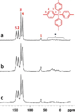
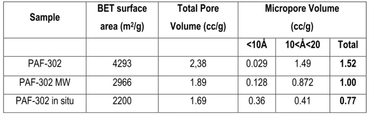
2.3 Results and discussion 42 2.3.1 Comparison of PAF-302 obtained with different methods 42
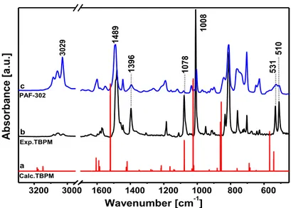
2.3.1.1 FTIR spectroscopy of PAF-302 43
2.3.1.2 Solid-state 13C MAS NMR 46
2.3.1.3 PXRD measurements 47
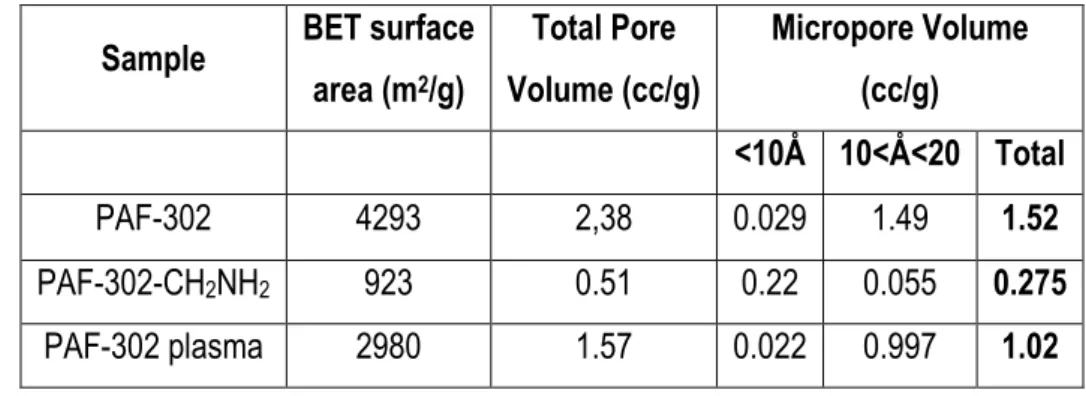
2.3.1.4 Thermogravimetric analysis (TGA) 47 2.3.1.5 Textural properties of PAF-302 samples 48 2.3.2 Modification of PAF-302 surface: Functionalization with amino groups 52
2.3.2.1 FTIR spectroscopy 54
2.3.2.2 Solid-state 13C MAS NMR 55
2.3.2.3 Thermogravimetric analysis (TGA) 56
2.3.2.4 PXRD measurements 57
2.3.2.5 N2 physisorption measurements 58
2.3.3 Methane Adsorption on PAF-302: FTIR and Theoretical Combined Studies 60
2.4 Conclusions 63
References 65
Chapter 3: Microporous hyper-crosslinked aromatic polymers: synthesis,
characterization and functionalization with amino groups
683.1 Introduction 68
3.2 Experimental 71
3.2.1 Standard procedure for the synthesis of mPAF materials with different TPM:FDA
ratio. 71
3.2.2 Post-synthetic temperature treatments of mPAF-1/16 71
3.2.3 Post-synthetic amination of mPAF-1/16 72
3.2.4 Synthesis of mPAF materials with different tetrahedral monomers 72 3.2.5 Friedel-Crafts reaction optimization: Effect of precursor concentration combined
with thermal treatment 73
3.3 Results and discussion 74
3.3.1 mPAF materials with different TPM:FDA ratio 74
3.3.1.1 FTIR Spectroscopy 75
3.3.1.3 PXRD measurements 77 3.3.1.4 Scanning electron microscopy analysis (SEM) 78
3.3.1.5 Thermogravimetric analysis (TGA) 78
3.3.1.6 Pore distribution and surface area 79
3.3.2 Post-synthetic temperature treatments of mPAF-1/16 81
3.3.2.1 Thermogravimetric analysis (TGA) 81
3.3.2.2 FTIR Spectroscopy 82
3.3.2.3 Solid-state 13C MAS NMR 84
3.3.2.4 N2 physisorption at 77K 84
3.3.3 Wet post-synthetic amination of mPAF-1/16 86
3.3.3.1 FTIR Spectroscopy 88
3.3.3.2 Solid-state 13C MAS NMR 88
3.3.3.3 Thermogravimetric analysis (TGA) 89
3.3.3.4 N2 physisorption at 77K 90
3.3.4 mPAF polymers with different tetrahedral monomers 92
3.3.4.1 FTIR Spectroscopy 94
3.3.4.2 Solid-state 13C MAS NMR 95
3.3.4.3 Thermogravimetric analysis (TGA) 96
3.3.4.4 PXRD measurements 97
3.3.4.5 Pore distribution and surface area 97
3.3.5 Friedel-Crafts reaction optimization: preliminary characterization 99
3.3.5.1 Infrared spectroscopy (FTIR) 100
3.3.5.2 Thermogravimetric analysis (TGA) 102
3.3.5.3 N2 physisorption at 77K 104
3.4 Conclusions 107
References 108
Chapter 4: Experimental and theoretical gas adsorption on the
synthesized polymers
1104.1 Introduction 110
4.2 PAF-302: Experimental and theoretical gas adsorption 112 4.2.1 Specific surface area and pore volume determination by Argon physisorption 113 4.2.2 Experimental and theoretical high-pressure CH4 and H2 adsorption isotherms 116
4.3.1 mPAF-1/16 polymer: Experimental and theoretical Argon physisorption 120
4.3.2 mPAF-1-/16 crystal structure from modeling 121
4.3.3 mPAF-1/n polymers: Experimental N2, CO2 and CH4 adsorption 124
4.3.4 mPAF-1/16 polymer : simulated uptake of CH4 and CO2 128
4.3.5 PAF-302 Vs. mPAF-1/16: CH4 volumetric adsorption 129
4.4 Zero Length Column method (ZLC) for CO2 uptake measurements 130
4.5 Conclusions 134
References 135
General conclusions
138Acknowledgements
141Appendix 1: Instrumental Parameters
142i
The main subject of the present Ph.D. dissertation is the synthesis and characterization of novel microporous organic polymers and the determination of their gas (H2, CH4 and CO2) storage capacity. Microporous
materials (with pores of less than 2 nm in diameter) have recently attracted considerable attention due to the variety of applications in which they can be used, including heterogeneous catalysis, gas purification, gas separation and gas storage. This research work is part of an industrially driven project that aims at the synthesis and characterization of microporous aromatic polymers to be used for H2 and CH4 storage and CO2
capture.
In Chapter 1, the systems mainly suitable for hydrogen, methane and carbon dioxide storage are described along with their textural properties. Gas storage applications mainly require materials with high surface area and high micropore volume. Different classes of materials having these characteristics such as porous carbons, MOFs (Metal Organic Frameworks) and a organic microporous polymers have been widely studied. The latter can be divided in different subclasses (PAFs, CMPs, HCPs and PIMs…etc), which have in common a structure formed by light elements (H, B, C, O and Si) linked by strong covalent bonds. They normally show high thermal and chemical stability, and can be synthesized with a plethora of organic reactions and building blocks, which provide flexibility for the material design to achieve desirable pore properties.
This PhD thesis has been focused on the synthesis and characterization of the porous aromatic framework (PAF) and hyper-crosslinked polymers (HCP), two classes of materials that can be obtained by different synthetic strategies: the Yamamoto homo-coupling reaction used to synthesize PAF materials and the Friedel-Crafts reaction suitable to obtain HCP polymers. These coupling reactions lead to the formation of new C-C bonds starting from precursors with specific functionalities. These materials and their syntheses will be discussed in Chapters 2 and 3.
In particular, in Chapter 2, an optimized synthesis of PAF polymers and their characterization with several physico-chemical techniques are described. The synthetic procedure was further optimized with the aim to reduce the cost of the synthesis. Besides the optimization of the experimental conditions to obtain reproducible high surface area materials with lower costs, particular attention was paid to improve the storage capacity, especially for CO2 capture, by introducing amine groups in the material.
In Chapter 3, HCP polymers synthesized from different tetrahedral precursors and FDA as crosslinking agent are described. In the first part of the work, we evaluated how different precursor/FDA ratios change the textural porosity of the resulting polymers. Then, using the optimized conditions, we synthesized new HCP materials with different tetrahedral aromatic monomers. As for PAF, post-synthesis treatments were adopted for
ii
thermal treatment under different conditions, and (II) functionalization with different amine groups.
PAF and HCP materials have been extensively characterized using the most common techniques to determine structure (FTIR, SS-NMR), chemical composition (elemental analysis), crystallinity (PXRD), thermal stability (TGA), surface area and pore distribution (N2 physisorption at 77K).
In Chapter 4, the results of gas uptake on selected synthesized materials, at different temperatures and pressures are considered. High pressure storage (up to 200 bar) of methane and hydrogen was used to evaluate the maximum uptake capacity of PAF-302. Methane and carbon dioxide storage up to 10 bar were measured for some HCP materials, along with their heat of adsorption and CO2/N2 selectivity. For all materials
CO2 storage was evaluated using the Zero Length Column (ZLC) method, at 0.1 bar and 35 ºC which are the
real conditions of a typical flue gas stream from post-combustion application. This allowed a rapid screening of materials because the analysis time of each sample is short.
Abbreviation Meaning
ANG Adsorbed Natural Gas
BET Branauer, Emmet, Teller
CCS Carbon Capture And Storage CMP Conjugated Microporous Polymer
CNG Compressed Natural Gas
COD 1,5-cyclooctadiene
COF Covalent -Organic Frameworks
DCE Dichloroethane
DMF N,N-Dimethylformamide
DMSO Dimethyl Sulfoxide
EA Elemental Analysis
FDA Formaldehyde Dimethyl Acetal
FTIR Fourier Transform Infrared Spectroscopy
HCP Hyper-Crosslinked Polymer
LNG Liquefied Natural Gas
MOF Metal–Organic Frameworks
NLDFT Non Local Density Functional Theory
PAF Porous Aromatic Framework
PCFF Polymer Consistent Force Field PIM Polymers Of Intrinsic Microporosity
PPN Porous Polymer Network
PSD Pore Size Distribution
PXRD Powder X-Ray Diffraction
QSDFT Quenched Solid Density Functional Theory SEM Scanning Electron Microscopy
SSA Specific Surface Area
SS-NMR Solid State Nuclear Magnetic Resonance TBPM Tetrakis(4-bromophenyl)methane
TETA Triethylenetetramine
TGA Thermal Gravimetric Analysis
THF Tetrahydrofuran TPA Tetraphenyladamantane TPE Tetraphenylethene TPEa Tetraphenylethane TPM tetraphenylmethane TPS Tetraphenylsilane TPT Tetraphenyltin
1
Gas Storage in Porous Materials
1.1 Introduction
In recent years, porous materials have attracted tremendous interest, investments and efforts in scientific research and technological development around the world. They possess unique surface, structural, and bulk properties that make them relevant in various fields such as ion exchange [1, 2], adsorption (for separation) [3, 4], catalysis [5,6], and gas storage [7-10]. In this introduction chapter the main storage systems for hydrogen, methane and carbon dioxide, as well as their porosity and surface area, will be described in relation to the main classes of porous materials that have been proposed for gas storage.
1.2 Gas storage and capture
The growing world population and the increasing standard of living increase the concerns over the sustainability of oil reserves: the supply of economically usable hydrocarbon resources in the world is limited, and the demand for hydrocarbon fuels is increasing. In the current hydrocarbon economy, transportation is fuelled primarily by petroleum. The burning of hydrocarbon fuels has an adverse effect on the environment as it is responsible for the increase in the earth's atmosphere of CO2 and other pollutants. A number of potential
solutions for conservation and remediation of the environment due to CO2 increment are cutting edge research
topics. These include work in CO2 capture and storage[11], as well as the use of cleaner fuels, such as natural
gas (CH4) [12] or hydrogen (H2) [13,14].
1.2.1 Hydrogen Storage
Hydrogen is considered a potentially relevant fuel for the automobile industry because it is the most abundant element in the universe, it contains the highest energy density per unit mass, and it burns cleanly, producing only water. Unfortunately, molecular hydrogen that can be used as fuel does not occur naturally in convenient reservoirs. It needs to be produced by steam reforming of hydrocarbons, water electrolysis or by other methods [15,16].
Possible approaches for hydrogen storage include [17]:
2
Physical storage of cryogenic hydrogen (cooled to -253°C, at pressures of 6-350 bar) in insulated tanks;
Storage in advanced materials — within the structure or on the surface of certain materials — as well as in chemical compounds that can undergo a chemical reaction to release hydrogen.
Hydrogen has a very high energy content by weight (about three times higher than gasoline), but it has a very low energy content by volume (liquid hydrogen is about four times lower than gasoline).
Currently, hydrogen is stored either in high pressure tanks or in liquid form in cryogenic tanks. These forms of storage are not suitable for widespread commercial application as the energy density of hydrogen even at about 700 bar or in liquid form is only 4.4 and 8.4 MJ/L, respectively, compared to the energy density of gasoline, namely, 31.6 MJ/L. In addition, there are significant energy costs in storing hydrogen in these forms, not to mention associated safety issues [18].
The alternative is the use of solid porous materials for hydrogen storage. The US department of Energy (DOE) has set quite stringent targets for hydrogen storage capacity for mobile applications that are yet to be met: the targets are 5.5 wt.% as gravimetric capacity (1.8 kWh/kg system), and 0.04 kg/L (1.3 kWh/L system) as volumetric capacity to be achieved by 2017. It should be noted that these are system requirements, and not just targets for the storage capacity of the material itself. In addition, the storage should be safe, durable (1500 operational cycle life), and cost-effective. No existing systems has met these conditions, yet [17].
As far as the interaction/adsorption of hydrogen with/on a material is concerned, there are mainly three different approaches [18]:
Physisorption: hydrogen remains molecular and binds weakly on the surface of the most common porous materials with a binding energy in the meV range. Hence, it desorbs already at very low temperatures. Sorbent materials belonging to this category are carbon-based materials such as nanotubes, fullerenes, graphene, mesoporous silica, metal–organic frameworks (MOFs), covalent -organic frameworks (COFs), and clathrates [19-21].
Chemisorption: H2 molecule dissociates into individual atoms, migrates into the material, and binds
chemically with a binding energy lying in the 2-4 eV range. As the bonding is strong, the desorption takes place at higher temperatures. Complex hydrides, which are light metal hydrides, are the main class of materials where hydrogen is held in strong covalent bonds [22-23].
The third form of binding occurs when the bond between H atoms in a H2 molecule is weakened but
3
(binding energy in the 0.1-0.8 eV range). This type of adsorption concerns carbon-based nanostructured materials such as nanotubes, fullerenes and graphenes doped with metals and transition metals [24-26].
Figure 1 summarizes the different types of materials being studied for hydrogen storage along with the challenges that they have to face [18].
Figure 1. Summary of various hydrogen storage materials and their limitations (Figure adapted from ref. 18)
Metal hydrides are reversible under ambient conditions but are too heavy. Simple chemical hydrides are reversible but only at very high pressure and temperature. Complex chemical hydrides have high hydrogen density but suffer from poor reversibility. Nanostructured materials are very promising but are yet to emerge as practical materials. In fact they offer good reversibility but require very low temperatures of storage. The kinetic of hydrogen adsorption by microporous materials is very rapid, which is a practical advantage for hydrogen storage, but low temperatures are required to achieve significant capacities at useful storage pressures. In practice, low temperature storage requires cooling, which inevitably makes heavier the storage unit and is therefore a significant disadvantage. In order to achieve high volumetric capacities, adsorbed hydrogen must be stored at relatively high densities within the pores.
For these reasons, the hydrogen adsorption capacity of microporous materials at ambient temperature is currently too low for practical use [27]. The actual research in this field is to enhance the interaction of hydrogen with the materials to reach an adsorption capacity sufficiently high for real applications.
4 1.2.2 Methane Storage
Economical and environmental considerations have also boosted interest in Natural gas (NG) as a fuel for transportation, and especially as a replacement for petrol (gasoline).
In the generation of energy from methane, the major concern is the production of CO2, though it is
comparatively less than other fossil fuels (gasoline or diesel). Indeed, methane has a gravimetric heat of combustion (55.7 MJ kg-1) comparable to that of gasoline (46.4 MJ kg-1), but it boasts the smallest amount of
CO2 per unit of heat produced among fossil fuels, and it is naturally abundant. However, the lack of efficient
storage methods has so far prevented the widespread use of NG in motor vehicles.
The two common methods of NG storage currently used are (1) liquefaction at low temperature (down to 120 K) and (2) compression to 200–300 bar at room temperature.
The volumetric energy density of Liquefied Natural Gas (LNG) is lower (22.2 MJ L-1, 112 K) than that of
gasoline (34.2 MJ L-1) but requires the storage in expensive cryogenic vessels and it suffers from boil-off
losses. On the other hand, Compressed Natural Gas (CNG) necessitates the use of heavy, thick-walled cylindrical storage tanks and multi-stage compressors to achieve a reasonable volumetric energy density, which is actually only 27% (9.2 MJ L-1) with respect to gasoline [28]. Despite efforts to improve cylinders and
compressors, the amount of NG stored in a CNG tank permits for only a short driving autonomy on light-duty passenger vehicles, and high pressure storage on vehicles has been associated to safety concerns [29]. In order to take advantage of the benefits that the use of NG in vehicles may offer, attractive alternatives to CNG and LNG are needed. It has been suggested that porous adsorbents represent a safer, simpler, and potentially more cost-effective method for storing NG at ambient temperature and reasonable pressures (around 35 bar) in the form of adsorbed NG (ANG) [30].
Similarly to hydrogen storage, also for CH4 the adsorption can be physical (weak van der Waals forces) or
chemical (significant covalent interactions) depending on the type and on the strength of the interaction between methane molecules and the material surface sites. From an application standpoint, the primary difference between physisorption and chemisorption is the significant disparity in binding energies. For reversible gas storage and delivery, moderate binding energies (measured as heat of adsorption) are required to maximize energy efficiency of the system. Therefore, physisorptive materials are best suited for this application, as chemisorptive materials would require a substantial amount of external heat to release the adsorbed gas.
5
To address the need for better technologies, in 1993, the U.S. Department of Energy (DOE) set the methane storage target as 150 cm3 (STP)/ cm3 at 298 K and 35 bar [31]. In 2000, this target was updated to 180 cm3
(STP)/ cm3 [32]. As a result of efforts by a number of researchers, some MOFs exhibited considerably high
methane uptakes, which exceeded the above DOE target [33].
In 2012, the U.S. DOE initiated a “Methane Opportunities for Vehicular Energy (MOVE) Program”, and re-set several targets to guide the research on adsorbent-based methane storage [34]. The major target is that the adsorbent-level volumetric energy density should exceed 12.5 MJ L-1 and 9.2 MJ L-1 after packing losses
(25%), at room temperature and low pressure (less than 35 bar). This corresponds to a volumetric storage capacity of 0.25 g cm-3 or 350 cm3 (STP)/ cm3 for the adsorbent material. Even assuming no packing loss, the
volumetric storage capacity still needs to be higher than 260 cm3 (STP)/ cm3 [35].Clearly, this is an ambitious
target, which none of the currently known adsorbent materials meet. In fact, even for the previously widely-referred, much lower target of 180 cm3 (STP)/ cm3, there are only few materials known to reach this value [33,
36, 37]. Additionally, DOE set a target concerning the gravimetric energy density, 0.5 g (methane) g-1
(adsorbent), or 700 cm3 (STP) g-1, which is equally challenging.
The ideal sorbent should also show resistance to impurities typically encountered in natural gas sources with a lifetime of at least 100 fill–release cycles, and it should be cost effective approaching, $10/kg sorbent, in addition to other system level targets such as desorption rates, tank abuse tests,…etc [29].
1.2.3 Carbon Dioxide Capture and Storage (CCS)
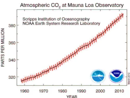
Beside the development of technologies for the use of methane [38] and hydrogen [39] as clean fuels, industrial technologies for carbon dioxide capture are vital in environmental safety. Due to growing levels of greenhouse gas emissions (Figure 2), separation of CO2 from mixtures of gases such as the gas emitted from
6
Figure 2. The increment of CO2 concentration during the period 1958–2010 (at Mauna Loa Observatory), in
the atmosphere. (Figure adapted from ref. 41)
Carbon capture and storage (CCS) is an efficient way to reduce CO2 concentration in the atmosphere. It is a
three-step process including separation of CO2 from other gases before reaching the atmosphere, CO2
transportation, and its permanent storage [41]. Among them, the CO2 capture is the most challenging key step
for which new adsorbent materials need to be developed. Conventional adsorbent materials rely on either chemisorption or physisorption to capture CO2.
There are three major approaches for CCS: pre-combustion capture, oxy-fuel process and post-combustion capture [42]:
In pre-combustion, the fossil fuel is partially oxidized in a gasifier. The resulting syngas (CO and H2) is
shifted into H2 and CO2, which can be captured from the stream.
Oxy-combustion occurs when the fuel is burned in the presence of oxygen. The resulting flow gas consists mainly of pure CO2 which can be transported to the sequestration site and stored.
The post combustion capture is based on removing CO2 from the flow gas after combustion. Instead
of being released directly into the atmosphere, flue gas is passed through a particular equipment that separates/captures most of the CO2.
Post-combustion capture offers some advantages since existing combustion technologies can still be employed without radical changes. This makes post-combustion capture easier to implement as a retrofit option compared to the other two approaches.
7
Various technologies such as membrane separation, cryogenic distillation and adsorption can be used for CO2
capture. The adsorption is the ideal way to achieve efficient CCS. It is a separation technology, able to reduce both cost and energy of post-combustion capture compared to other technologies. Selective capture and subsequent storage of carbon dioxide in porous materials has been considered as a promising new approach [11].
The adsorbents used for CO2 capture can be placed into two categories: physical and chemical adsorbents
[43].
Chemisorption is a sub-class of adsorption, driven by a chemical reaction occurring at the exposed surface. Chemical adsorbents are mostly metal compounds such as metal oxides and metal salts.
Physisorption is a process in which the electronic structure of the atom or molecule is barely perturbed upon adsorption. The major physical adsorbents reported for CO2 adsorption include activated
carbons and inorganic porous materials such as zeolites.
However, the success of this approach is dependent on the development of adsorbents with high capacity and selectivity; Ideally, this has to be environmentally benign, renewable, safe, and cost-effective [41].
In summary, the goal remains in the development of low-cost and high-performance adsorbents for CO2
sequestration, gas separation and energy storage applications.
1.3 Porosity and Surface area
Porous materials are most frequently characterized in terms of pore sizes derived from gas sorption data, and IUPAC (International Union of Pure and Applied Chemistry) conventions have been proposed for classifying pore sizes and gas sorption isotherms that reflect the relationship between porosity and sorption.
1.3.1 Adsorption isotherms
The adsorption of guest molecules onto a solid surface plays an essential role in determining the properties of porous compounds. Depending upon the strength of the interaction, all adsorption processes can be divided into chemical and physical adsorption categories. Chemical adsorption or chemisorption involves valence forces of the same type as those operating in the formation of chemical compounds, whereas physical adsorption or physisorption is a general phenomenon which occurs whenever a gas (the adsorbate) is brought into contact with the surface of a solid (the adsorbent), in this case the forces involved are intermolecular
8
forces (van der Waals) and always include the long-range London dispersion forces and the short-range intermolecular repulsion [44].
Adsorption is described through isotherms, which correlate the amount of gas adsorbed to the pressure in the system at a constant temperature. The adsorbed gas quantity is always normalized to the mass of adsorbent to allow the comparison with other materials.
The textural analysis of powders is usually performed by physisorption of nitrogen, argon and krypton at cryogenic temperatures (77.4 K and 87.3 K). From a proper isotherm, it is possible to extract information about surface area, pore size and porosity of a given material.
IUPAC proposed to classify pores by their internal pore width:
Pores exceeding ̴50 nm widths are called macropores;
Pores between 2 and 50 nm widths are called mesopores;
Pores not exceeding ̴ 2 nm widths are called micropores, which are further divided into those < 0.7 nm (ultramicropores) and those in the 0.7 – 2 nm range (supermicropores).
The sorption behaviour in mesopores is distinct from the adsorption phenomena occurring in micropores. The mesopore adsorption is dominated by capillary condensation, which is responsible for a sharp adsorption enhancement around the mid relative-pressure region. Conversely the adsorption in a micropore should not be considered as that of molecules onto a solid surface but as the filling of molecules into a nanospace where a deep potential field is generated between the adsorbate molecules and the pore walls. In this case, the adsorption isotherm shows a steep rise at very low relative pressure and a plateau after saturation [45].
Based on IUPAC classification, there are six representative adsorption isotherms that reflect the relationship between porous structure and type of sorption (Figure 3a) [46].
9
Figure 3. (a) Types of physisorption isotherms; (b) Types of hysteresis loops
These adsorption isotherms are characteristics of microporous (Type I), nonporous and macroporous (types II, III and VI), and mesoporous (type IV and V) adsorbents.
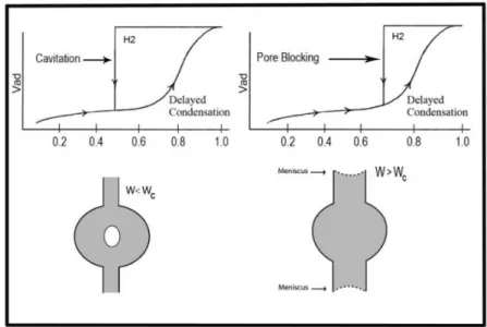
An empirical classification of hysteresis loops was given by IUPAC (Figure 3b), in which the shape of the hysteresis loops (types H1 – H4) is correlated to the adsorbent texture. According to this classification [46, 47]: Type H1 is often associated with porous materials exhibiting a narrow distribution of relatively uniform
(cylindrical-like) pores.
Materials that give rise to H2 hysteresis contain a more complex pore structure in which network effects such as pore blocking percolation and cavitation are relevant (Figure 4) [48-50].In case of pore blocking (sometimes called ink-bottle) desorption from the pore body may occur only after emptying its neck. In other words, desorption from the neck triggers evaporation in the blocked pore. Thus, the vapour pressure of desorption from the pore body depends on neck size, network connectivity, and on the state of the neighbouring pores. While the mechanism of desorption involves cavitation phenomena (spontaneous nucleation and growth of gas bubbles in the metastable condensed fluid) when the neck diameter is smaller than a certain critical width (estimated to be ca. 6 nm for nitrogen at 77.4 K). In this case, the pore body empties while the pore neck remains filled.
10
Isotherms with type H3 hysteresis do not exhibit any limiting adsorption at high P/P0. This behaviour
can be caused by the existence of non-rigid aggregates and in principle should not be expected to provide a reliable assessment of either the pore size distribution or the total pore volume.
H4 hysteresis loops are generally observed with complex materials containing both micropores and mesopores.
Figure 4. Schematic illustration of pore blocking and cavitation controlled evaporation. Adapted from ref. 46.
Great progress was achieved in the understanding of adsorption, capillary condensation, and desorption phenomena in highly ordered mesoporous materials with simple pore geometries, such as MCM and SBA-type mesoporous silica crystals [51]. However, there are still many open questions concerning adsorption - desorption mechanisms in more complex porous systems. Fluids adsorbed in hierarchically structured micro-mesoporous materials exhibit a great variety of hysteretic adsorption-desorption isotherms with multiple steps related to phase transformations in adsorbed phases. Adsorption -desorption processes involve a combination of physical mechanisms, such as delayed condensation, advanced condensation, cavitation-induced evaporation, pore blocking, and percolation, which are reflected in characteristic types of hysteresis loops formed by adsorption and desorption isotherms [52].
The hysteresis loops causes a considerable complication for the pore structure characterization; however, if interpreted correctly, hysteresis loops can provide important information on pore network morphology, which is crucial for discriminating the physical mechanisms of phase transformation [53].
11 1.3.2 Surface area measurements and pore size distribution
The specific surface area (SSA) is a relevant textural parameter of adsorbent materials. Conventionally, the Brunauer-Emmett-Teller (BET) gas adsorption method has become the most widely used standard procedure for the determination of the SSA, in spite of the over simplification of the theoretical model on which is based [44].
In particular, the BET model applied to the N2 adsorption data at 77 K has been widely used to characterize
the adsorbent material of interest. It assumes that once a monolayer becomes saturated, a further monolayer can form on top, and that the rates of adsorption and desorption are equal for each layer.
It is usual to apply the BET equation in the form:
This can be rearranged to:
Where P/V(P0-P) linearly correlates with P/P0, and the values of Vm and c can be obtained from the slope
[(c-1)/Vmc] and intercept [1/(Vmc)] of the straight line. Knowing the monolayer volume and the area occupied by
one adsorbate molecule, the BET surface area (S) can be derived:
The range of linearity is restricted to a limited part of the isotherm — usually the 0.05—0.30 P/P0 range.
Therefore, the SSA of any material can be measured by knowing the amount of sample, the amount of gas adsorbed in the monolayer and the area occupied by a single adsorbed molecule. Nitrogen (area of 16.2 Ǻ2) is
12
the most commonly used gas for BET measurements: this method allows the calculation of SSA ranging from 0.01 to 6000 m2/g.
For materials with a wide range of pore sizes including ultramicropores (pores smaller than 7 Å), the diffusion of nitrogen at 77K is very slow. This leads to time-consuming measurements of adsorption isotherms determined in non-equilibrium conditions. In order to overcome this inconvenience, Argon adsorption at its boiling temperature (87.3 K) has been proposed as an alternative gas for a more reliable determination of the textural properties (pore size and surface area analyses) of microporous solids [45].While nitrogen is a diatomic molecule with a quadrupole moment which produces specific interactions at the gas–solid interface, argon is much less interacting: for example, argon has no dipole or quadrupole moment, allowing to provide a more accurate scenario of the porous structure for a given solid. Compared to nitrogen, argon adsorption reveals a much more straightforward correlation between the pressure where micropore filling occurs and the pore size. This assumption, together with the higher boiling temperature (87.3 K), shifts argon pore filling to higher relative pressures (as compared to nitrogen at 77.4 K), which helps to reduce some kinetic restrictions usually associated with nitrogen adsorption at 77.4 K.
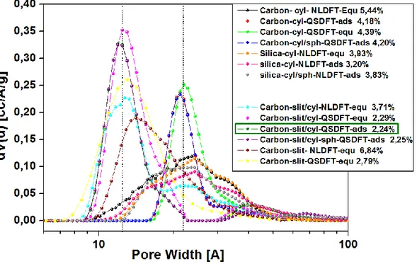
Pore size distribution can also be calculated from the isotherm using specifically developed models based on size and shape. Several different approaches are used to characterize the pore size distributions. In order to achieve a more realistic description, microscopic theories describing the sorption and the behaviour of fluids in narrow pores on a molecular level are necessary. Since the development of the PSD (pore size distribution) calculation methods, the Non Local Density Functional Theory (NLDFT) method, has been widely used for the characterization of micro- and mesoporous materials [54].
Briefly, the evaluation of PSD is based on the theoretical isotherms calculated for individual pores of a given adsorbate–adsorbent system. These isotherms, which constitute the so-called kernel, are generated using the NLDFT method where the fundamental molecular parameters characterizing the gas–gas and gas–solid interactions of the adsorption system are employed. The mathematical procedure used to calculate PSD can be described as the fitting between theoretical and experimental isotherms: the obtained PSD represents volumetric contributions of pores with different sizes whose theoretical isotherms best fit the experimental data [55].
13 1.4 Adsorbent properties for best performance gas storage
The work of this thesis primarily concern with the study of physical adsorption in different porous materials. Each gas and its associated applications have criteria that should be met for any gas storage material to be of use in practice. In general, there are different sets of performance criteria for a good adsorbent as listed below [56]:
High adsorption capacity. One of the most important parameters is the high specific surface area (SSA). However, simple considerations based on SSA are not enough to obtain an efficient material: also the sizes of the pores are of considerable importance, as adsorption predominantly occurs within the pores that are able to create a sufficiently high attractive potential. Such a situation is met as soon as the pore walls are so close to each other that their own potential fields overlap. This affects the bonding strength of the molecules to the adsorbent surface, which is related to the isosteric heat of adsorption [57].
Thus, the most relevant properties that affect the gas adsorption capacity are SSA, surface chemical nature, and pore size. These parameters determine how much adsorbates can be accumulated per unit mass of adsorbents.
High selectivity. For multicomponent mixtures, selectivity is highly desirable for gas separation. The selectivity of an adsorbent will depend on pore size, shape and pore size distribution as well as on the nature of the adsorbate components.
Favorable adsorption kinetics. Adsorption kinetics is determined by the particle (crystallite) size, and by the macro-, meso and microporosity of the adsorbent. Sometimes, binder type and amount would also affect the interparticle transport and thus the global adsorption process kinetics. For a favourable kinetic, the adsorption rate should be high or controllable depending on the requirements of a particular application.
Excellent mechanical properties. Adsorbents need to be mechanically strong and robust enough to stand attrition, erosion and crushing in adsorption columns or vessels. High bulk density and crushing strength, and attrition resistance are desirable.
Good stability and durability in use. Adsorbents are often subject to harsh chemical environments or to high pressure and thermal conditions. A high stability in those environments/conditions is essential in ensuring long life or durable utilization.
Obviously, the practical challenges concern the preparation of high performance materials in a simple and cost effective manner and the materials should meet the above requirements/criteria as much as possible.
14 1.5 Porous materials for gas storage
In recent years, nanoporous materials have been a core focus of scientific and technological importance because of their ability to adsorb within their extended interior surface and pore space atoms, ions and molecules. The main classes of materials that show good performances for gas storage are[28, 58-62]:
1) Porous inorganic materials (e.g. zeolites) 2) Porous Carbons
3) Metal Organic Framework materials (MOFs, also known as Porous Coordination Polymers (PPCs)) 4) Microporous organic polymers (PIMs, COFs, CMPs, HCPs, PAFs... etc)
1.5.1 Porous inorganic materials: zeolites
Zeolites are a family of microporous aluminosilicates formed from AlO4 and SiO4 tetrahedra. They are
crystalline materials with well-defined structures and amongst the most widespread chemical materials used today. Their ordered crystalline nature gives them uniform cavities and channels with dimensions in the microporous regime (Figure 5). The framework structures are relatively rigid and, as with all microporous solids, they have high SSA and large pore volumes.
15
Several types of zeolites are industrially produced and are widely used in different applications, which include purification of gases and liquids by removal of impurities [63, 64], catalysis in petrochemical industries [65], molecular sieves [66], gas sensors [67] and gas separation membranes [68].
Zeolites have a number of significant practical advantages over other microporous adsorbents in that, for example, they possess high thermal stability. However, it seems unlikely that zeolites could be useful as practical gas storage media as discussed by Felderhoff et al. [69]. The problems encountered when using zeolites as adsorbents for the storage of gas are the following [70]:
i) The presence of non-structural porosity given by aggregations of zeolite particles, which diminish the amount of material in the same volume and thus worsen the gas storage.
ii) Zeolites with hydrophilic character may preferentially adsorb traces of water found in gas mixtures, with a consequent reduction in storage capacity.
iii) Relatively low surface areas (<1000 m2/g).
1.5.2 Microporous carbons
Several types of porous carbons such as activated carbons, carbon nanotubes and nanofibres and microporous templated carbons have attracted interest for gas storage [71]. From a practical point of view, porous carbons are already commercially produced in large quantities for a broad range of applications and are relatively inexpensive.
Among porous carbons, activated carbons are the most widely studied family. They are a family of synthetically modified carbon-based materials containing very small graphite crystallites and amorphous carbon (Figure 6). These materials generally are prepared from a carbonaceous starting materials (coal, wood, coconut husks …. etc) by a thermal treatment or chemical treatment, which can lead to polymeric systems with large surface areas, often well in excess of 1000 m2g-1 and even up to >3000 m2g-1 [72].
16
Figure 6. Representation of the pore structure of activated carbons
Carbon dioxide adsorption capabilities for activated carbons are typically 2-3 mmol/g at 25 °C and 1 atmosphere pressure, but recently an activated carbon prepared from sawdust, AC-2-600, showed an enhanced carbon dioxide adsorption capacity of 4.8 mmol/g under the same conditions [73, 74].
As for methane, one of the best activated carbons reported in the literature, Maxsorb® carbon (Kansai coke based) [75] with a surface area of 3100 m2 g-1, is characterized by a storage capacity of 211 mg g-1 at 298 K
and 35 bar.
Unfortunately, due to their method of production, most activated carbons have a wide distribution of pores sizes ranging from microporous to macroporous. Additionally, the surface of activated carbons is chemically well defined with a mixture of oxygen and nitrogen functional groups. These two factors combine to give an excellent adsorbent material for a wide range of species, though it suffers from poor selectivity for specific molecules. Moreover, improvement of the storage capacity for porous carbons is currently limited by the difficulties in increasing the surface area above 3500 m2 g-1, being this parameter strongly correlated with the
amount of gas that can be stored in the material.
1.5.3 Metal−Organic Frameworks (MOFs)
In recent years, a new family of materials, porous metal−organic frameworks (MOFs) or coordination polymers in a broader sense, have emerged as promising adsorbents for gas storage.
17
MOFs consist of metal ions or clusters coordinated to organic linkers (Figure 7) to form three-dimensional framework structures like “crystal sponges”. The large combination of metals joints and organic linkers, the large surface areas, and tunable pore sizes make MOF compounds highly attractive for storing gas [76-78]. The intense interest in these inorganic-organic hybrid solids [76] has resulted in a vast array of new compounds proposed in the recent literature for the hydrogen, methane or carbon dioxide storage [79, 11, 35].
Figure 7. (a) Building blocks for MOF-5 (IRMOF-1), 3D-[Zn4O (bdc)3], (b) ball-and-stick representation of the
tetrahedral {Zn4O} secondary building unit with the carboxylate groups which span the edges of the {Zn4O}
tetrahedron in an octahedral fashion and (c) the crystal structure packing diagram as ball-and-stick, with polyhedral {Zn4O}, and as space-filling representation. Adapted from ref. 80.
The most interesting feature of these materials is that they can be highly porous with internal surface areas that can reach the record value of 10 400 m2 g-1 for MOF-210 [81]. For comparison this value is significantly
higher than zeolites, which typically have surface areas of several hundred m2g-1. Additionally, this class of
porous materials has unique features, such as structural flexibility and exposed metal sites, which give them more potential for future development.
The highest gravimetric adsorptions of CO2 have been reported in frameworks with high surface areas and
pore diameters lower than 15 Å. The framework [Zn4O(btb)2] (MOF-177) with a surface area of 4500 m2g -1, for
instance, exhibits the highest capacity for CO2, taking up to 33.5 mmol g-1 at 32 bar [82].
MOFs with coordinatively unsaturated metal centres, such as PCN-14 [33], HKUST-1 [83] and MOF-74 [84], have been considered as the most promising MOFs for methane storage, with storage capacity that exceed 180 cm3(STP)/ cm3.
18
MOFs exhibiting particularly high hydrogen storage capacities include MOF-210 [81] and NU-100 [85]. These two materials have reported gravimetric hydrogen adsorption capacities of 176 mg g-1 and 164 mg g-1,
respectively.
However, these materials are generally less robust than zeolites and microporous carbons, because they exhibit lower thermal and chemical stability that hinder them from usage under extreme conditions.
Nevertheless, their commercialization is already under way, principally by BASF who market a series of framework materials under the trade name Basolite TM, and so the practical application and use of these materials on an industrial scale is clearly feasible.
1.5.4 Microporous organic polymers
Porous Organic Polymers is another class of microporous materials of great interest in literature. They can be divided in several subclasses of polymers, which have in common the following features [86]:
The structure is formed by light elements (H, B, C, O and Si) that are linked by strong covalent bonds (B–O, C–O, C–C, B–C, and Si–C).
A high thermal and chemical stability to air and atmospheric moisture since they are linked by strong covalent bonds.
Normally, they do not have a long range order. Thus, their structure is amorphous due to irreversible bond formation governed by a kinetic control.
They can be constructed using a plethora of organic reactions and building blocks, which provides flexibility for the material design to achieve desirable pore properties. In all the materials is possible to use a wide range of organic functionalities using different synthetic strategies and a great choice of monomers that makes it easy to introduce various functional groups in the pore walls [87].
They show high specific surface area and microporosity, two properties of fundamental importance in gas storage. Actually, they are the reference point for the evaluation of the capacity of an adsorbent material.
The main classes of microporous organic polymer that are considered as potential candidates for gas storage are: Polymers of Intrinsic Microporosity (PIMs), Covalent Organic Frameworks (COFs), conjugated Microporous Polymers (CMPs), Hypercrosslinked Polymers (HCPs) and Porous Aromatic Frameworks (PAFs) [88].
19 1.5.4.1 Polymers of intrinsic microporosity (PIMs)
Polymers of intrinsic microporosity (PIMs) are a group of polymeric materials which do not require a network of covalent bonds in order to show microporosity; indeed intrinsic microporosity in polymers is defined as “a continuous network of interconnected intermolecular voids, which are formed as a direct consequence of the shape and rigidity of the component macromolecules” [89, 3].
PIMs are amorphous solids due to their random packing and lack of long-range order, but possess surface areas in the range of 400 – 1760 m2/g [3, 90]. Usually they are formed by a double nucleophilic aromatic
substitution reaction between a tetrahydroxylated monomer and a tetrafluorinated monomer, resulting in the formation of dioxane links between monomer units (Figure 8). It is essential for the production of a microporous PIM that one of the monomers has a highly rigid and contort structure.
Figure 8. Typical synthesis of PIM polymer (a) and molecular model(b). Adapted from ref. 3
Hydrogen uptakes of up to 2.7 wt%, at 10 bar and 77 K, have been reported for a triptycene-based polymer (trip-PIM) [91].
20 1.5.4.2 Covalent organic frameworks (COFs)
Covalent organic frameworks (COFs) are a family of porous crystalline macromolecules made solely from light elements (C, H, N, B and O) organic building blocks, which are linked together by strong covalent bonds [92, 93].
COFs possess rigid structures, long-range order, high thermal stability (up to 600 °C) and permanent porosity with extremely high surface areas, up to 6450 m2/g [94].
The synthetic routes for COFs may be different, and the most used are the self-condensation of aromatic boronic acids and the co-condensation between boronic acids and aromatic diols in which the covalent bonds are boronic esters (Figure 9); these synthetic routes are very economic since a simple dehydration process without the use of catalysts or other reagents are necessary.
Figure 9. The building blocks and structure model for COF-18 Å [95].
Each connector/linker combination forms a specific 2D or 3D framework with topology based on the geometry and the type of reactive functional groups[96]. COFs are attractive materials because their organic nature allows total control over their structural parameters, including composition and porosity. Thus, they are ideal for gas storage applications. The storage capabilities of COFs for gases, such as hydrogen, methane, and carbon dioxide, have been widely investigated [7, 97, 98].
As for methane, the highest COF storage capacity was observed for COF-102, which had a value of 187 mg g -1. COF-103 also demonstrated a high capacity of 175 mg g- 1. These values are comparable to values
21
On the other hand, the largest hydrogen storage capacity is observed for 3D COF-102 (SBET: 3620 m2 g- 1) [7],
which uptakes 72 mg per gram at 1 bar and 77 K. This capacity is comparable to those of MOF-177 (75 mg g -1, SBET: 4500 m2 g- 1) and MOF-5 (76 mg g-1, SBET: 3800 m2 g-1).
As far as CO2 storage is concerned, Yaghi and co-workers have reported that the CO2 uptake of COF-102
reaches 27 mmol g-1 at 298 K and 35 bar [7].
However, COFs suffer from poor gas selectivities, as the large pore size does not usually provide a preferential site of adsorption for one gas over another and, among the microporous organic polymers they tend not to be particularly stable to moist air, which is obviously a problem and limits their potential as useful materials [99].
1.5.4.3 Conjugated microporous polymers (CMPs)
Conjugated microporous polymers (CMPs) are a class of porous materials with amorphous three-dimensional organic framework made up of multiple carbon–carbon bonds and/or aromatic rings that form an extended conjugated network. CMPs were first reported in 2007 [100] and took advantage of Sonogashira–Hagihara palladium coupling to link aromatic halides to aromatic alkynes, thus forming poly(aryleneethynylene) (PAE) networks, with BET surface areas that exceed 1000 m2/g in some cases [101, 102].
CMPs are formed under kinetic control and display no long-range order, but their pore sizes are well-defined and can be controlled by careful selection of the monomers [101]. Surface areas can also be controlled by changing the linker length, with the number of micropores decreasing with increasing linker length. This behavior can be explained by the extra flexibility granted to the framework by longer linkers, that allows a more efficient packing and decreases the available surface area.
Thanks to the study on PAEs it was discovered that: (i) similarly to the crystalline materials, such as MOFs and COFS, the surface area and pore distribution can be modulated according to the type of organic linker that
connects the monomers, and (ii) that the structural order is not a prerequisite for controlling of microporosity. The gas sorption capacity of conjugated porous materials is effectively comparable with classical porous materials such as zeolites and active carbons. H2 storage capacity of CMPs based on poly(aryleneethynylene)
was studied by Cooper and coworkers who reported that the CMP with the largest BET surface area (1018 m2
g-1)shows a H2 storage capacity of 1.4 wt% [103].
Ren et.al. reported CO2 capture by CMP polymers[104]: The most successful of these materials is TNCMP-2,
22
surface area of 995 m2/g, shows excellent CO2 uptake (up to 2.62 mmol/g at 273K and 1 bar or 1.45 mmol/g at
298K and 1 bar) and high CO2:N2 selectivity (up to 25.2:1 at 298K and 1 bar).
The research performed on CMPs has focused on broadening the range of functional groups that can be incorporated into the frameworks, with the aim to tune the properties of the materials for different applications. CMPs are currently attracting considerable interest as materials that combine the mechanical stability of polymers with adjustable optoelectronic properties of organic molecules. In fact, species belonging to the family of conjugated polymers have already been exploited for some applications like optoelectronic (OLED (Organic Light Emission Diode) for photovoltaic cells and FET transistor [105, 106].
1.5.4.4 Hypercrosslinked polymers (HCPs)
HCPs represent a class of low cost porous materials, which can be prepared mainly by the Friedel Crafts alkylation reaction. The permanent porosity in HCPs is a result of extensive crosslinking reactions, which prevents the polymer chains from collapsing into a dense, nonporous state [107].
The crosslinking produces a highly rigid network structure with high thermal stability that is not commonly expected for organic polymers. Combined with their light weight properties, small pore size, micropore volume and high surface areas, HCPs can be considered as promising materials for H2 and CO2 storage applications
[108, 109].
According to the synthetic method, HCPs can be produced by the following procedures [110]:
1. Intermolecular and intramolecular crosslinking of preformed polymer chains (either linear chains or lightly crosslinked gels). “Davankov-type” resins are the first type of hypercrosslinked materials, which have been well-studied and are prepared by post-crosslinking of linear polystyrene (PS), poly(vinylbenzyl chloride), or their pre-crosslinked copolymers with a divinylbenzene (DVB) moiety [107]. The hypercrosslinking process consists of two simple steps (Figure 10): first, the linear or lightly crosslinked polymer precursors are dissolved or swollen in a thermodynamically good solvent; this introduces space between the polymer chains. Then, the precursors are quickly cross-linked via a Friedel-Crafts alkylation reaction using a Lewis acid, such as iron (III) chloride, forming a HCP polymer chains locked in an expanded form.
23
2. Direct step growth polycondensation of suitable monomers: this is an approach to microporous organic networks that uses bis(chloromethyl) aromatic monomers such as dichloroxylene (DCX), bis(chloromethyl)biphenyl (BCMBP), and bis(chloromethyl) anthracene (Figure 11) [102]. The HCP polymers obtained using these precursors are predominantly microporous and exhibit apparent BET surface areas of up to 1904 m2 g- 1 as measured by nitrogen adsorption at 77K [111]. Schwab and coworkers [112] have
copolymerized BCMBP with a set of non-functionalized fluorene-based comonomers such as fluorine (FLUO), 9,9′ -spirobi(fluorene) (sFLUO), dibenzofuran (DBF), and dibenzothiophene (DBT) resulting in copolymer networks, which exhibit BET surface areas up to 1800 m2 g-1.
Figure 11. Example of monomers used for the synthesis of the HCP networks. Adapted from ref. 111
3. Knitting aromatic compound polymers (KAPs) using an external crosslinking agent. This procedure has been recently developed and consists in the simple one-step Friedel-Crafts reaction between an aromatic monomer and formaldehyde dimethyl acetal (FDA): in the presence of FeCl3 as catalyst various aromatic
monomers can be directly crosslinked to form the highly porous networks (Figure 12 ) [113].
Figure 10. (a) Schematic representation of the Hypercrosslinking process; (b) Reaction scheme for the synthesis of a HCP polymer prepared from gel poly(divinylbenzene-co-vinylbenzyl chloride). Adapted
from ref. 110
24
Figure 12. Scheme showing the synthetic pathway of HCP polymers using an external crosslinking agent. Structures a, b and c are example of building blocks for the network. Adapted from ref. 113
Buyi Li and coworkers have used this method to “knit” rigid aromatic building blocks, such as benzene, biphenyl, 1,3,5-triphenylbenzene, methylbenzene, chlorobenzene, and phenol obtaining surface areas up to 1391 m2/g [113]. Also Cooper group demonstrated that this “knitting” approach can produce networks with
surface area of up to 1470 m2 g- 1 when using the tetrahedral monomer, tetraphenylmethane [114].
This method avoids the need for monomers with specific polymerizable groups and also avoids the use of precious metal coupling catalysts. Various functional groups can also be easily introduced into the porous frameworks just by choosing the proper monomers [115, 113].
Based on the combination of large specific surface area and enhanced microporosity, HCPs show good potential for gas storage [110].
Networks based on BCMBP exhibit a H2 storage capacity of 3.68 wt% at 15 bar and 77.3 K. The isosteric heat
of sorption for H2 on these materials is found to be in the range 6–7.5 kJ mol-1 [111].
The physisorption of CH4 in organic porous materials has been less investigated than H2 as CO2 storage.
Cooper and coworkers synthesized microporous HCPs based on poly(p-dichloroxylene), which show methane uptake up to 5.2 mmol g-1 (116 cm3 g- 1 ) at 20 bar and 298 K [9]. This value is comparable with many other
microporous systems but falls short of materials with higher micropore volumes [116]. However, it is worth noting that these materials demonstrate a high isosteric heats of sorption for CH4 (20.8 kJ mol- 1 ).
It was found that the CO2 capture capacities were related to the textural properties of the HCPs [117]. The
performance of these materials to adsorb CO2 at atmospheric pressure was characterized by maximum CO2
uptakes of 1.7 mmol g- 1 (7.4 wt%) at 298 K. At higher pressures (30 bar), the polymers show CO2 uptake up to
25
13.4 mmol g- 1 (59 wt%), superior to zeolite-based materials [118]and commercial activated carbons [7]. In
addition, these polymers showed low isosteric heats of CO2 adsorption and good selectivity towards CO2.
These results confirmed that the HCPs have potential to be applied as CO2 adsorbents in pre-combustion
capture processes where high CO2 partial pressures are involved.
The properties of HCPs can be fine-tuned for a specific purpose by post synthetic modification[119]. This is possible because the hypercross-linking reaction does not occur at each possible site, resulting in residual chloromethyl groups being present in the polymeric matrix. Thus, functional groups, such as amines or alcohols, can be transferred to the polymer matrix by replacing these residual chlorine atoms. This enables to improve the storage capacity of these materials and extends their application as adsorbents for toxic organic [120] and inorganic contaminants [4].
1.5.4.5 Porous aromatic frameworks (PAFs)
Porous aromatic frameworks (PAFs) are a family of microporous polyphenylic networks characterized by a three-dimensional, rigid and open-network structures. In 2009, Ben group [121, 122] developed a method to synthesize the first long range ordered porous aromatic framework (PAF) with diamond-like topology (PAF-1 or PAF-302), which had a record surface area (SBET = 5640 m2 g-1) at that time and exceptional
physicochemical stability via a nickel(0)-catalyzed Yamamoto-type cross-coupling reaction.
The original idea for the synthesis of PAF-1 came from the structure and properties of diamond, in which each carbon atom is tetrahedrally connected to four neighboring atoms by covalent bonds. Breaking the C–C covalent bond of diamond and inserting rigid phenyl rings allow sufficient exposure of the faces and edges of phenyl rings with the expectation of increasing the internal surface areas.
For a long time it was thought that the low surface area of porous organic polymers was due to the amorphous structure, but thanks to PAF-1, it has been shown that even non-crystalline materials could reach very high surface areas. This exceptional surface area, according to Hong-Cai Zhou [123], is mainly due to three factors: (1) The highly efficient Yamamoto reaction helps to eliminate unreacted termini at the monomers and therefore highly connected frameworks are formed [124] (2) The default diamondoid framework topology, imposed by the tetrahedral monomers, provides widely open and interconnected pores to efficiently prevent the formation of “dead space”. (3) The prevailing robust covalent C -C bond connecting the whole framework leads to a material with exceptionally high thermal and chemical stability.
26
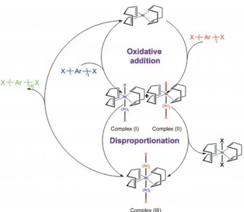
The Yamamoto coupling is an aryl–aryl coupling of aryl-halogenide compounds mediated mostly by stoichiometric amounts of bis(1,5-cyclooctadiene)nickel(0) (Ni(COD)2 for short) (Figure 13).
Figure 13. (a) Synthetic route for PAF-1 (x = C), PPN-4 (X = Si) and PPN-5 (X = Ge, (b) the default non interpenetrated diamond-like network of PAF-1.
The polymerization is advantageous as a self polycondensation with just a single, halogen-functionalized monomer can be used to form an organic framework.
Compared to other C–C coupling reactions, such as Sonogashira–Hagihara routes and Suzuki cross-coupling, Yamamoto coupling shows the unexpected halogen elimination ability of the ending group. This makes it unique to prepare ultrahigh porosity solids because heavy ending halogen atoms evidently decrease the surface area.
Several papers [10, 123, 125, 126] have been published on PAF-1 analogues obtained by replacing the central carbon with other quadricovalent building centers (adamantane, silicon, and germanium) (Figure 13) using the same method presented by Ben and co-workers [121], but with some variation on temperature, solvent and washing method.
Compared with other ultrahigh surface area solids such as porous carbons, porous silicas, zeolites, MOF and microporous polymers, PAFs show very high thermal (>450°C) and excellent physicochemical stabilities. They are also characterized by excellent adsorption abilities for CO2, H2 and CH4 [10, 125, 126].
PAF-1 with surface area of 5640 m2/g, demonstrates high adsorption capacity for hydrogen (10.7 wt% at 77K
and 48 bar) , carbon dioxide (50 wt% at 298K and 40 bar) and methane ( 15 wt% at 298K and 35 bar) [121, 126],and a heat of adsorption (Qst) of 5.4 kJ mol-1, 14.0 kJ mol-1 and 15.6 kJ mol-1 for H2, CH4 and CO2,
respectively [10].
Furthermore, PPN-4, PAF material obtained starting from quadrivalent tetraphenylsilane, has a BET surface area of 6461 m2 g-1, which represents a world record BET surface area [125]. In relation to this impressive
27
surface area, PPN-4 can adsorb 2121 mg g-1 CO2 (212 wt%) at 50 bar/295 K, 158 mg g-1 hydrogen at 77 K/80
bar and 389 mg g-1 methane at 298 K/55 bar.
To improve gas adsorption capacity in PAFs, post-synthesis treatments have also been proposed in literature: 1) KOH activation of PAF-1 at high-temperature [127]:The Carbonization was carried out by heating the
PAF-1/KOH powder mixture under N2 at 2 °C/min and a temperature ranging from 500 and 900 °C for
1 hour. After carbonization, the BET surface area of PAF-1 derivatives decreased to about 1000 m2 g -1, but showed a unique bimodal microporous structure located at 0.6 nm and 1.2 nm which revealed
high Carbon dioxide, methane and hydrogen sorption in both low-pressure and high-pressure environments. In particular, K-PAF-1-750 is able to store 1320 mg g-1 of carbon dioxide (40 bar, RT),
207 mg g-1 of methane (35 bar, RT) and 71.6 mg g-1 of hydrogen (48 bar, 77 K). The carbon dioxide
and methane high-pressure storage ability surpassed the original PAF-1.
2) Introduction of sulfonic groups onto the biphenyl frameworks. PAF-1 has been modified by reaction with chlorosulfonic acid to give sulfonate grafted acid (PPN-6-SO3H) and lithium salt (PPN-6-SO3Li)
species. After sulfonation, the surface area of PPN-6-SO3H and PPN-6-SO3Li was reduced to 1254 m2
g-1 and 1186 m2 g-1 but the Qst increased to 30.4 and 35.7 kJ mol-1. Strong
interactions between the sulfonate-graft samples and carbon dioxide lead to a very high uptake capacity at 295K and 1 bar, with values of 13.1 and 13.5 wt% (equivalent to 3.6 and 3.7 mmol g-1) for
28 References:
[1] Dyer, A. An Introduction to Zeolite Molecular Sieves (Wiley, Chichester, 1988). [2] Hölderich, W., Hesse, M. and Näumann, F. Angew. Chem. int. 1988, 27, 226−246.
[3] McKeown, N. B.; Budd, P. M. Polymers of intrinsic microporosity (PIMs): organic materials for membrane separations, heterogeneous catalysis and hydrogen storage. Chem. Soc. Rev. 2006, 35, 675–683.
[4] Li, B.; Su, F.; Luo, H. K.; Liang, L.; Tan, B. Hypercrosslinked microporous polymer networks for effective removal of toxic metal ions from water. Microporous and Mesoporous Mater. 2011, 138, 207–214.
[5] Du, X.; Sun, Y.; Tan, B.; Teng, Q.; Yao, X.; Su, C.; Wang, W. Tröger’s base-functionalised organic nanoporous polymer for heterogeneous catalysis . Chem. Commun. 2010, 46, 970–972.
[6] Dang, D.; Wu, P.; He, C.; Xie, Z.; Duan, C. Homochiral metal-organic frameworks for heterogeneous asymmetric catalysis. J. Am. Chem. Soc. 2010, 132, 14321–14323.
[7] Furukawa, H.; Yaghi, O. M. Storage of Hydrogen, Methane, and Carbon Dioxide in Highly Porous Covalent Organic Frameworks for Clean Energy Applications. J. Am. Chem. Soc. 2009, 131, 8875–8883.
[8] McKeown, N. B.; Gahnem, B.; Msayib, K. J.; Budd, P. M.; Tattershall, C. E.; Mahmood, K.; Tan, S.; Book, D.; Langmi, H. W. and Walton, A. Towards Polymer-Based Hydrogen Storage Materials: Engineering Ultramicroporous Cavities within Polymers of Intrinsic Microporosity. Angew. Chem. 2006, 118, 1836–1839. [9] Wood, C. D.; Tan, B., Trewin, A.; Su, F.; Rosseinsky, M. J.; Bradshaw, D.; Sun, Y.; Zhou, L. and Cooper, A. I. Microporous Organic Polymers for Methane Storage. Adv. Mater. 2008, 20, 1916–1921.
[10] Ben. T.; Pei. C.; Zhang. D.; Xu. J.; Deng. F.; Jing. X.; Qiu. S. Gas Storage in Porous Aromatic Frameworks (PAFs). Energy Environ. Sci. 2011, 4, 3991-3999.
[11] Deanna, M. D.; Berend, S.; Jeffrey R. L. Angew. Chem. Int. Ed. 2010, 49, 6058–6082.
[12] Frota, W.M.; Sa, J.A.S.; Moraes, S.S.B.; Rocha, B.R.P.; Ismail, K.A.R. Natural gas: The option for a sustainable development and energy in the state of Amazonas. Energy Policy. 2010, 38, 3830-3836.
[13] Jain, I.P. Hydrogen the fuel for 21st century. Int. J. Hydrog. Energy. 2009, 34, 7368-7378.
[14] Kelly, N.A.; Gibson, T.L.; Cai, M.; Spearot, J.A.; Ouwerkerk, D.B. Development of a renewable hydrogen economy: optimization of existing technologies. Int. J. Hydrog. Energy. 2010, 35, 892-899.
[15] Nath, K.; Das, D. Production and storage of hydrogen: Present scenario and future perspective. J. Sci. Ind. Res. 2007, 66, 701-709.
[16] Pasculete, E.; Condrea, F.; Radulescu, C. Hydrogen and sustainable energy. Research for hydrogen production. Environ. Eng. Manag. J. 2007, 6, 45-49.
[17] U.S. Department of Energy's Energy Efficiency and Renewable Energy Website. https://www1.eere.energy.gov/hydrogenandfuelcells/storage/current_technology.html(2010).