1
1
A textural classification of argillaceous rocks and their durability
2
3
Jordi Corominas
1, Joan Martínez-Bofill
1,2, Albert Soler
34
5
(1) Department of Geotechnical Engineering and Geosciences. UPC-BarcelonaTech
6
(2)Geomar. Enginyeria del Terreny. SLP
7
(3) Grup de Mineralogia Aplicada i Medi Ambient, Department de Cristal·lografia, Mineralogia i Dipòstis Minerals,
8
Universitat de Barcelona.9
10
e-mail: [email protected] ph. +(34).93.401.686111
12
ABSTRACT13
14
Argillaceous rocks can display a wide range of durability behaviour after excavation and in cut slopes. In
15
this paper we propose a classification of argillaceous rocks based on their textural characteristics. Three
16
main components of the classification scheme are: the clastic framework, the fine-grained matrix and the
17
cementing agent. Unlike other schemes, the unlithified argillaceous sediments are included as well. The
18
names proposed for the rocks broadly follow the existing nomenclature used in petrographic
19
classifications. The durability of some argillaceous rock types has been assessed by taking into account a
20
set of degradation features of the excavated slopes. It has been observed that the ratios of these textural
21
components exert a strong control on the long-term durability of slopes.
22
23
Key words: argillaceous rock, durability, slope deterioration, classification
24
25
26
INTRODUCTION27
28
Argillaceous rocks are frequent in the nature. They form around two thirds of the stratigraphic column
29
(Blatt, 1982) and about one third of all rocks exposed at the earth surface (Franklin, 1983). Although
30
strictly speaking an argillaceous rock is a rock made of clay, in its practical usage it has a broader
31
meaning and it is equivalent to terms such as lutite or mudrock. It encompasses rocks such as argillite,
32
claystone, siltstone, mudstone, shale, clay shale, or marl (Potter et al, 2005). They are all mostly
33
siliciclastic rocks whose predominant constituent particles are silt and/or clay-size. Though argillaceous
34
rocks are mainly composed of detritus from preexisting rocks, they may contain significant amounts of
35
chemically precipitated cement (such as calcium carbonate, silica, iron oxide, among others).
36
37
The mineralogy of the argillaceous rocks is controlled by the source of the sediment and the conditions of
38
the depositional environment. Typical clastic components are quartz, feldspar and phyllosilicates such as
39
mica, chlorite, illite and other clay minerals. During diagenesis, compaction and cementation transform
40
sediment into a rock. This is an ongoing process involving the progressive reduction of void space and the
41
crystallization of authigenic minerals that results in an increase in strength and decrease in
42
compressibility and permeability. This process is summarized by Czerewko and Cripps (2006).
43
44
It is difficult to assess when argillaceous sediment becomes rock because the conversion of sediment into
45
rock is a continuous process. Soils are defined as natural aggregates of mineral grains that can be
46
separated by gentle mechanical means such as agitation in water while rocks are natural aggregates of
47
minerals connected by strong and permanent cohesive forces (Terzaghi and Peck, 1967). The soil-rock
48
boundary is usually established based on their strength. British Standards (BS5930:1999) define a lower
49
limit for the undrained shear strength of very stiff soils of 150 kPa and an upper unconfined compression
50
strength for weak rocks of 12.5 MPa. Other limits have been proposed by other researchers (i.e. Hawkins,
51
2000). The boundary between hard soil and soft rock is commonly recognized around 1 MPa (Marinos,
52
1997; Czerewko and Cripps, 2006) although there is no complete agreement on this limit since these
53
materials are part of a continuum (Johnston and Novello, 1993).
54
55
Argillaceous rocks display a contrasting behavior in construction works. Blasting is often required to
56
excavate these rocks. However, the newly excavated slope surfaces may experience physical weathering
57
and disintegrate in a very short span of time, over a period of months to years. The shallow, progressive,
58
physical and chemical alteration of rock material and its subsequent detachment and removal or
59
2
redistribution by transport agents is defined as deterioration (Nicholson, 2004).
60
61
Weathering predisposes the instability of the excavated slopes (Calcaterra and Parise, 2010). Although
62
surface deterioration of cuts is perceived as having low risk it affects the safety of the users and involves
63
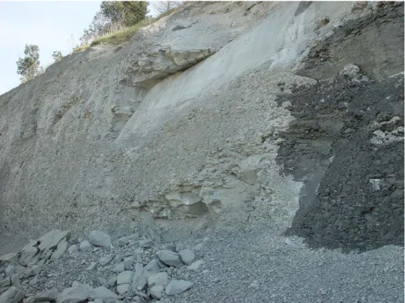
costly maintenance works (Martínez-Bofill et al. 2004). Listric joints may develop parallel to the slope
64
face being a main source of instability (Fig. 1). This type of discontinuities is seldom identified in
65
boreholes or in field surveys as they develop mostly after the rock has been exposed. The exposed rock
66
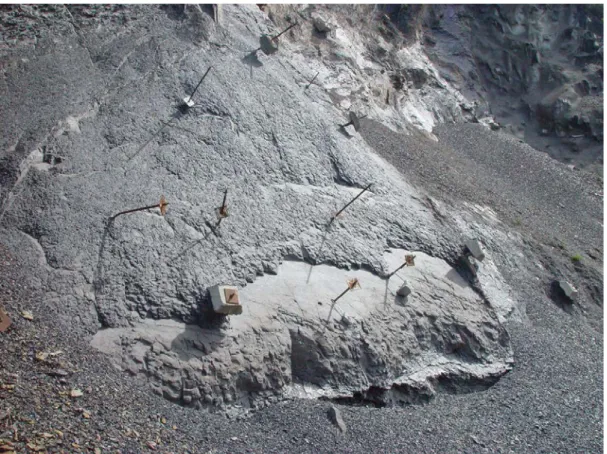
surface may experience swelling and breakdown facilitating the erosion and compromising the
67
appropriate performance of the remedial and/or stabilization measures (Fig. 2). When interbedded layers
68
of limestone, sandstone or conglomerate are present, disaggregation of the argillaceous rock results in
69
overhangs, which may produce topples and failures, especially if vertical joints parallel to the slope face
70
exist (Fig. 3).71
72
73
74
Figure 1. Slope surface deterioration with the development of listric (curvilinear) failures on mudstones in
75
the C-17 road at Tona, Barcelona province, NE Spain.
76
3
78
Figure 2. Cutslope surface deterioration in the N-1 road at Ormaiztegi in the Gipuzkoa province, N Spain.
79
The argillaceous rock decomposes around the bolt thus preventing its proper operation.
80
81
82
Figure 3. Differential weathering along the C-16 road at Navàs, Barcelona province, N Spain. Spalling
83
and disaggregation of the mudstone have generated overhangs in the sandstone layers which eventually
84
fall.
85
86
The described behavior cannot be generalized and some road cuts in argillaceous rocks may remain
87
4
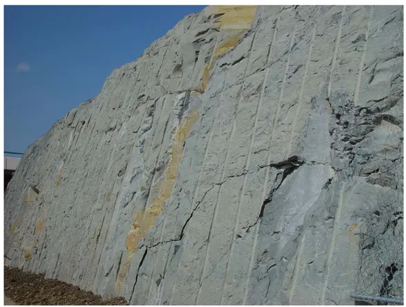
virtually unweathered without signs of degradation for years (Figure 4).
88
89
90
91
92
Figure 4. Slightly deteriorated cut slope. Well preserved blast holes are observable several years after the
93
excavation of the slope in the C-17 road at Torello, Barcelona province, NE Spain.
94
95
96
This contrasting behavior has attracted the interest of engineers involved in the design, construction and
97
maintenance of embankments, road cuts and tunnels. In fact, most the maintenance cost is due to the
98
inability to accurately identify and classify these rocks, and anticipate their behavior.
99
100
CHARACTERIZATION OF THE ARGILLACEOUS ROCKS FOR ENGINEERING PURPOSES
101
102
Many attempts have been made to classify and characterize the argillaceous rocks in order to predict their
103
behavior. Classical soil analyses such as particle size and Atterberg limits are not appropriate for
104
characterizing the argillaceous rocks because they cannot be easily disaggregated. Porosity, degree of
105
saturation and fissuring are parameters that govern the strength and deformability of the argillaceous
106
rocks. Similarly to other rocks, the Uniaxial Compressive Strength (UCS) tends to increase with the
107
increase of packing density. Recent reviews on the wide range of properties and on the engineering
108
performance of stiff sedimentary clay were prepared by Chandler (2010), Simpson (2010) and Pineda et
109
al (2014). Weathering of the argillaceous rocks reduces UCS and shear strength (Taylor, 1988; Bhattarai
110
et al. 2006). Czerewko and Scripps (2006) summarized the variation of the mudrock properties with the
111
different stages of the diagenetic maturity. Despite all this work, several researchers have reported that
112
standard rock tests are unsuitable to properly characterize the long-term behavior for most of argillaceous
113
rocks and its durability (Czerewko & Cripps, 2006; Nickmann et al. 2006, 2010). The reason is that
114
routine geomechanical tests are oriented to determine rock strength or the capability to withstand loads
115
but they are not primarily focused to assess the susceptibility of the rock to weaken upon exposure and
116
disintegrate along time. In other words, they are not designed to assess the durability.
117
118
The durability of a rock expresses its ability to resist abrasion, wear and breakdown with time (Santi,
119
1998). There exist several converging points of views on the factors that govern durability of the
120
argillaceous rocks and mechanisms leading to slaking and dispersion of soil particles. Among them stand
121
the swelling produced by stress release and water absorption (Mitchel, 1993). After excavation stress
122
5
release results in the development of fissures. These microstructures, rock pores and fissures induce the
123
infiltration and evaporation of water (cycles of wetting and drying) with the subsequent volume changes
124
that produces the slaking of the rock.
125
Compaction and cementation are critical post-depositional processes that control the properties and
long-126
term behavior of the argillaceous rocks (Morgenstern et al 1974; Dick and Shakoor, 1997). In the first
127
stages of diagenesis, materials are poorly indurated and have a strong tendency to disaggregate upon
128
immersion in water. The prominent role of bonding on durability was highlighted by Mead (1936) and
129
Underwood (1967), who classified shales into two broad groups. The first includes the compacted shales
130
(mudrocks) which have been consolidated by the weight of the overlying sediments without intergranular
131
cement. Meteoric agents may return the consolidated argillaceous rock to an assemblage of minerals and
132
rock fragments. The second group includes cemented shales (mudrocks) that have a cementing agent
133
(calcareous, siliceous or ferruginous) or bonding material formed by recrystallization of clay minerals
134
which reduce porosity and enhance durability by preventing the entrance of water and air. The removal of
135
cement as well as the poor binding efficacy may become a cause for rock degradation.
136
The role of the stress history of the argillaceous rocks in controlling both the fabric and bonding of the
137
rock and explaining its mechanical behavior has been summarized by Alonso and Pineda (2006) and Gens
138
(2013). Bjerrum (1967) attributed the swelling of unloaded shales to release of the locked in strain energy
139
of the diagenetic bonds. The less indurated clays will more readily release the strain energy stored during
140
compaction
141
The fundamental influence of the mineralogy has been also discussed by several authors (Gökçeoglu et al.
142
2000; Sadisun et al 2005). Russell (1981) observed the low durability of shales was partly due to the
143
inefficient cementing by calcite. Instead, the presence of hard bands, shaly limestone, increased
144
significantly the durability. The strength of fine-grained argillaceous rocks is found inversely related to
145
the total percentage of clay minerals (Gökçeoglu et al. 2000; Ward et al. 2005) while the presence of
146
expandable minerals such as smectites (Czerewko et al. 2006), or sulfides (Quigley & Vogan 1970;
147
Grattan-Bellew and Eden 1975; Sadisun et al. 2005) enhances the response to changes in moisture content
148
or changes in pore water chemistry. High carbonate content is associated to the high durability of the
149
rocks (Gökçeoglu et al. 2000). In most of these studies the influence of the mineralogical content on the
150
durability of the rocks has been established by means of statistical relations. However, neither a precise
151
nor the quantitative proportions of the mineralogical constituents governing the durability have been
152
proposed so far.
153
Most widely-used tests to assess rock durability are the Slake Durability Test (SDT) (Franklin and
154
Chandra, 1972) or the Jar Test (Wood and Deo, 1975) which aim at determining the effects of alternate
155
drying and wetting on the durability of soil and rock. Although these tests may be useful for assessing the
156
short-term performance of certain argillaceous rocks, the extensive experience on their performance
157
indicates that their results are far from yielding fully satisfactory results in the characterization of the
158
long-term durability of argillaceous rocks (Nickmann et al. 2006). This is attributed to the fact that
159
durability is not dependent on a single property but on combination of parameters such as the porosity,
160
compressive strength (expression of the bond strength of the matrix), grain size distribution, texture (grain
161
or matrix supported), mineralogical constituent, degree of cementation and stress history (Santi, 1998;
162
Cripps et al. 2006; Nickmann et al. 2006; Martínez-Bofill, 2011).
163
164
A CLASSIFICATION SCHEME FOR ARGILLACEOUS ROCKS
165
The successful construction and performance of engineering works in argillaceous rocks depends on
166
correctly anticipating the long-term behavior of these particular materials. As discussed above,
167
conventional laboratory tests often prove to be unable to fully characterize durability while the search for
168
predictors of the long-term behavior of the weak rocks after their exposure is still a challenge.
169
6
The mineralogy (Grainger, 1983), particularly expansive clays (Dick, 1992; Dick and Shakoor, 1992) and
170
the cementation (Shakoor and Brock, 1987) are widely accepted as important factors controlling the
171
deterioration of the rock cuts. Consequently, it might be possible to establish a relationship between the
172
mineralogical constituent, the cement content and the durability of the argillaceous rocks. The names of
173
sediments and sedimentary rocks have been traditionally proposed based on a wide range of criteria such
174
as the mineral content, texture, and other physical attributes as well as the depositional environment,
175
genetic relationship and economic importance (Hallsworth and Knox, 1999). However, as stated by Gens
176
(2013), a shortcoming of classifications based only on grain size is that they give no information on the
177
intensity of bonding or lithification, which is an important aspect in the context of durability. In order to
178
overcome these drawbacks we present a new classification scheme for the argillaceous rocks.
179
A classification should meet the needs of providing a concise and systematic method for designating
180
various types of rocks, and, if engineering properties are important, the classification should also enable
181
to derive soil properties. The proposed classification scheme is based on the rock texture which
182
specifically accounts for the bonding constituent. This classification does not attempt to replace the
183
existing and widely accepted terms. It also does not intend to change the established proportions of the
184
constituents of the argillaceous rocks and soils. Only when several options exist, we have selected the
185
most appropriate one.
186
The previously proposed classification involving argillaceous rocks are first reviewed, retaining their
187
original terms. Traditionally, sediments and sedimentary rocks have been classified independently and do
188
not take into account of schemes for other sediments and rocks with which they overlap. Thus, limestone,
189
sandstone and ironstone are classified separately although in nature they share strong compositional and
190
genetic links. Furthermore, the criteria used to classify each sedimentary group are usually different. As a
191
result, terms of sediment and sedimentary rocks tend to be inconsistent and lacking in basic or general
192
guidelines (Hallsworth and Knox, 1999). Many classification schemes of detrital sediments and rocks
193
have been proposed. Hallsworth and Knox (1999) and USGS (2004) presented complete reviews of the
194
existing classification schemes which will be taken as starting point.
195
Krynine (1948) used rock texture, including mineralogical content as criteria for classification. Grain size
196
was the primary criterion for grouping conglomerates, sandstones and fine clastics. Williams et al. (1982)
197
presented a ternary plot naming conglomerates and sandstones those clastic rocks having respectively
198
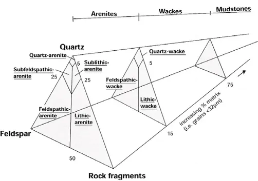
more than 50% of coarse fraction (pebbles and cobles) and sand. Folk (1954, 1980) based his
199
classification on the particle size (Figure 1). In his ternary plot the vertices are gravel, sand and mud. He
200
proposed the term conglomerate when gravels content exceed 80% and several combinations of the terms
201
gravel, sand and mud (silt and clay). This scheme has been widely accepted.
202
7
203
Fig.5 Classification of sedimentary detritic rocks (from Folk, 1954)
204
205
Pettijohn et al. (1972) adapted Krynine’s (1948) classification and introduced the term fine matrix to
206
distinguish between arenites and mudstones. Rock with more than 75% of fine-grained content
207
(<0.03mm) is named mudstone. Rocks with contents between 15 and 75% of fine particles are named
208
wackestone. Sand size aggregates with fine-grained content less than 15% (this boundary is 10% in the
209
proposal of the USGS 2004) correspond to sandstones.
210
211
212
213
8
Figure 6. Classification of the arenaceous rocks from Pettijohn et al. 1972 in USGS (2004).
On the other hand, carbonatic sediments and rocks (limestone, dolomite) are defined as having more than
214
50% of carbonate content. This percentage must not include the carbonatic cement although this
215
requirement is not necessary in the classification of the USGS (2004).
216
Several researchers suggest that the classification of the argillaceous rocks based on particle size and
217
mineralogical composition may not be appropriate due to the difficulty of separating the individual grains
218
from each other (Czerewko et al. 2006).
219
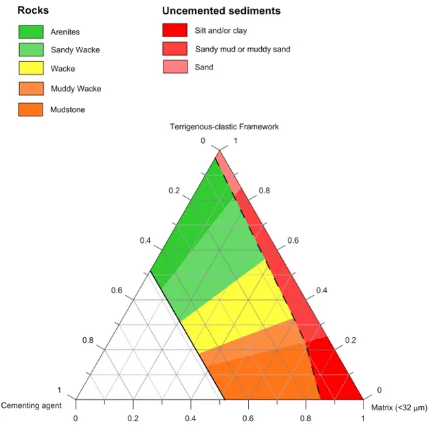
We propose a new classification, based on textural attributes of the argillaceous rocks. The nomenclature
220
consists of root names which combine information on grain size (grain framework, matrix) and the
221
amount of cementing agent. To classify a sample, one needs to determine the content of clastic
222
framework (sand size), matrix and cement.
223
The proposed scheme (figure 7) is based on a ternary plot in which the vertices are sand-size content
224
(between 0.032 and 2mm), mud-size content (< 0.032mm) and cement (calcium carbonate). The
225
boundary of 0.032mm is the one proposed by Dott (1964), Hallsworth and Knox (1999), and USGS
226
(2004). It is also found as practical boundary for visually identifying individual grains using a
227
petrographical microscope. Smaller sized grains often appear overlapped in thin sections and may be
228
subjected to misinterpretations.
229
The scheme includes the boundary proposed by Dott (1964) between arenites, mudstones, and wackes.
230
The latter are however considered arenaceous rocks. Despite this apparent inconsistency we have
231
included wackes in the classification of the argillaceous sediments because most of wackes are classified
232
as shales or mudstones in the field and because in the classification of terrigenous sediments, Folk (1954),
233
adopted by USGS (2004) the boundary between of mudrocks and sandy rocks corresponds to a relative
234
proportion of 50% of mud-size constituents.
235
We have adopted the same criterion as USGS (2004) for the compositional attribution of the grain-size
236
framework. No distinction has been made on whether the grain framework is mostly siliciclastic,
237
carbonate or other.
238
The argillaceous rocks may contain authigenic minerals formed during the diagenesis at temperatures and
239
pressures less than that required for the formation of the metamorphic rocks. In this classification of the
240
9
argillaceous rocks, the authigenic minerals may correspond to the anchimetamorphism that is the final
241
stage of the deep diagenesis or the first effects of metamorphism. (Kornprobst, 2003).
242
The term mud and mudstone is given to sediments and rocks containing at least 75% of fine grained
243
constituent. Mixtures of mud with sand with the former ranging between 75% and 15% are named
244
wackes. The predominance of fine components (up to 65%) or sandy components (up to 60%) qualifies
245
wackes as muddy wacke or sandy wacke respectively.
246
Cement is the textural constituent of the proposed classification not considered in other classification
247
schemes. Cement is a fundamental rock constituent that determines the strength and makes the difference
248
between soils and rocks. Cement is usually calcium carbonate (calcite) or calcium magnesium carbonate
249
(dolomite). However, cementing agents of a different composition (i.e. silica, iron oxide) may also be
250
present.
251
The proposed classification (Figure 7) establishes the boundary between sediments and rocks ranging
252
between 4% and 15% of cement content. This boundary is defined based on the recommended
253
percentages of cement used in soil stabilization (ACI, 1997, USACE, 1994). At the other extreme of the
254
plot, a 48% of cementing agent content has been taken to define the boundary between detritical rocks
255
and chemical sedimentary rocks. This value of 48% is the porosity of a simple cubic packing of
256
identically–sized spheres (Conway and Sloane, 1993) in which cement may grow. In chemical
257
sedimentary rocks, the cementing agent can be found not only as a post-sedimentary phase, but also
258
having been formed during the sedimentation.
259
10
260
Figure 7. Proposed textural classification of the argillaceous rocks
261
The mineral composition of terrigenous-clastic constituents can be determined reliably with the
262
petrographic microscope and by X-ray diffraction. Fine matrix has a size smaller than 32µm and may be
263
identified in the microscope as well. However, distinction between matrix and cement can be only
264
achieved if the cement crystals are bigger than 32µm (i.e. sparite in carbonate cemented rocks). Smaller
265
crystals (microsparite and micrite) are unresolvable for quantitative analysis with the petrographic
266
microscope and the cement cannot be distinguished from the matrix. In this case, the amount of cement
267
may be determined with a procedure such as the one described below.
268
QUANTIFIYING THE CONSTITUENTS OF THE ARGILLACEOUS ROCKS
269
Determining the components of the proposed classification scheme is not straightforward, because they
270
cannot be mechanically separated. Furthermore, the grain size of both cementing agent and fine matrix
271
11
are often unresolvable using a petrographic microscope. The fine grained cement cannot be distinguished
272
from the matrix thereby requiring an alternative procedure to separate the two constituents.
273
X-ray Fluorescence (XRF) and X-ray Powder Diffraction (XRD) are the techniques most frequently used
274
to determine the constituents of the argillaceous rock. XRF yields the chemical composition of the rock as
275
oxides of the different elements (Potts, 1992). This composition relates to the mineralogy but it does not
276
provide the real mineralogical species of the rock. For example the CaO content may correspond to
277
calcite, dolomite or Ca silicates (plagioclase), which may be either part of the detrital constituents of the
278
rock (calcite fragments and/or carbonated fossils), or cementing agent, or both.
279
The XRD is a rapid analytical technique used for mineral identification of a crystalline material (Bish &
280
Post, 1989). The mineralogical content of the rock can be determined by the semi-quantitative Rietveld
281
analysis of X-ray powder diffraction, determining the amount of each mineral (Young, 1993). The
282
Rietveld XRD permits the accurate determination and quantification of the mineral species present in the
283
rock although no information is provided on whether these minerals are part of the terrigenous framework
284
or of the fine-grained matrix.
285
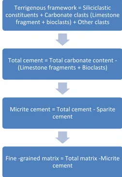
In order to overcome this uncertainty, we performed the following procedure (Figure 8) developed for
286
rocks containing carbonate cement (Martínez-Bofill, 2011). The procedure may be adapted for the
287
quantification of the components of the argillaceous rocks indurated with other cementing agents:
288
289
290
Figure 8. Procedure for determining the textural components of the argillaceous rocks (see explanations in
291
the text)
292
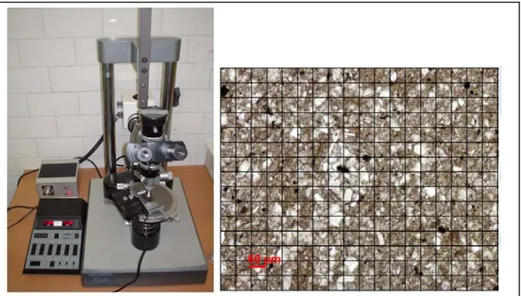
First, the terrigenous clastic framework, the matrix content and sparite cement (>32µm) are determined in
293
the optical microscope on thin sections of rock samples, provided with a point counter. Between 1000
294
and 2000 counts per section are recommended to be performed. Mineral constituents are obtained by
295
counting each mineral occurrence along a series of traverse line across the thin section (Figure 9).
296
Terrigenous framework = Siliciclastic constituents + Carbonate clasts (Limestone
fragment + bioclasts) + Other clasts
Total cement = Total carbonate content -(Limestone fragments + Bioclasts)
Micrite cement = Total cement - Sparite cement
Fine -grained matrix = Total matrix -Micrite cement
12
320
Figure 9. Determination of the clastic framework, matrix and cement bigger than 32µm in the
321
petrographic microscope (see explanation in the text).
322
323
All clasts are identified and counted using the polarizing microscope. The terrigenous framework is
324
mostly composed of siliciclastic constituents although it may contain clasts of calcium carbonate
325
composition (i.e. limestone fragments, bioclasts). The terrigenous framework is then divided between
326
carbonate clasts (limestone fragments, bioclasts) and the rests (mostly quartz, feldspars and lithic
327
fragments).
328
The total amount of carbonate content of the sample is determined with the Bernard calcimeter method
329
(UNE-103-200:93, ASTM D4373). The total carbonate content includes both carbonate clasts and
330
carbonate cement. By subtracting the amount of carbonate clasts from the total carbonate, the total
331
amount of cement is obtained. The latter is composed of sparite carbonate crystals (>32µm) and
332
microsparite and micrite (<32µm) which are included within the matrix. The micrite content which is
333
unresolvable with the petrographic microscope is obtained by subtracting the sparite content from the
334
total cement.
335
The fine-grained matrix contains all constituents smaller than 32µm including the micritic cementing
336
agent. The amount of silt and clay (mud) constituents is obtained by subtracting the microsparite and
337
micrite content from the total amount of matrix.
338
This procedure has been complemented when necessary by the Rietveld XRD. The latter is particularly
339
useful for double-checking the total calcium carbonate content measured with the Bernard calcimeter
340
(table 1) and for obtaining the composition of rock samples mostly composed of fine matrix, in which the
341
mineralogical constituents are unresolvable using a petrographic microscope.
342
Sample % CO2 Calcimetry % CO2 Calcite XRD Rietveld % CO2 Dolomite XRD Rietveld Difference Calcimetry- XRD A-2.1 m1 28,84 31,19 0,65 -3 A-2.1 m2 5,1 3,97 1,94 -0,81 A-2a.2 6,73 0 8,3 -1,5713
A-2.3 19,57 16,93 2,76 -0,12 A-2.5 19,57 16,24 2,65 0,68 A-2.6 30,44 29,59 2,16 -1,31 A-2.7 21,59 9,13 11,59 0,87 A-2.8 27,79 0 34,8 -7,01 C-16.1 m1 15,57 13,23 1,65 0,69 C-16.2 14,77 13,89 1,81 -0,93 C-16.3 13,94 12,77 0 1,17 C-16.4 m1 18,56 16,41 0,68 1,47 C-16.4 m2 8,49 8,11 1,63 -1,25 C-16.4 m3 23,83 21,43 0,37 2,03 C-16.6 17,9 15,32 0,6 1,98 C-16.7 9,81 7,2 2,77 -0,16 C-17.1 16,75 15,87 3,85 -2,97 C-17.2 16,91 16,59 2,87 -2,55 C-17.3 15,21 13,63 2,19 -0,61 C-17.4 8,66 7,77 4,91 -4,02 C-17.5 17,21 13,64 3,2 0,37 C-25.1 23,83 21,02 1,62 1,19 C-25.2 13,81 12,79 2,94 -1,92 C-25.3 18,81 15,34 2,81 0,66 C-25.4 m1 16,44 13,6 1,59 1,25 C-25.4 m2 17,32 17,25 1,39 -1,32 C-25.5 m1 8,18 8,28 0,77 -0,87 C-25.5 m2 8,09 7,8 2,59 -2,3 C-25.7 m1 17,32 19,47 0,91 -3,06 C-25.7 m2 22,73 16,97 1,39 4,37 C-25.9 13,06 12,49 3,02 -2,45 C-25.10 18,64 11,3 8,7 -1,3614
C-25.11 15,84 9,53 0,81 5,5 C-25.12 m1 10,04 10,32 2,3 -2,58 C-25.12 m2 11,62 9,36 0,89 1,37 C-25.13 18,82 12,4 3,33 3,09 C-25.14 m1 34,93 21,5 1,35 12,08 C-25.15 m1 36,62 29,91 1,24 5,47 C-25.16 16,66 12,32 2 2,34 C-25.17 2,2 0 0 2,2 C-55.1 m1 23,82 23,63 0,68 -0,49 C-55.1 m2 15,77 13,31 1,63 0,83 C-55.1 m3 16,21 12,18 1,3 2,73 C-154.1 m1 25,41 28,37 1,62 -4,58 L-301.1 m1 10,95 5,82 4,31 0,82 L-301.2 m1 20,57 13,45 1,25 5,87 L-301.2 m2 17,94 14,94 1,14 1,86Table 1. Total carbonate content of samples collected in different cut slopes in Spain (see next section)
343
measured with the Bernard calcimeter and the amount of calcite and dolomite obtained with X-ray
344
difractometry. Differences are usually less than 5%.
345
346
PERFORMANCE OF THE CLASSIFICATION
347
The performance of this classification has been assessed by analyzing the mid/long-term behavior
348
(between 2 and 30 years) of cut slopes excavated in different argillaceous rock formations of Catalonia
349
and Basque Country, in Spain.
350
The analysis consists of confronting the qualitative description of the deterioration features of the cuts
351
(taking into account the time of exposure) with both the Slake Durability Index (SDI) and the textural
352
composition of intact rock samples collected in the cuts. The cutslopes were first grouped based on their
353
deterioration stage. Contrary to other schemes aiming at assessing the susceptibility to deterioration (i.e.
354
Nicholson, 2004), grouping of the cut slopes is only descriptive and based on the present state of the slope
355
face. The deterioration stages are defined using the following descriptors (Martínez-Bofill et al. 2004)
356
(Figure 10):357
358
359
360
361
15
Cutslope Comment
Stage 1
More than 20 years old cutslope composed of sandstones in the C-17 road at Borgonyà, Spain. Drill holes are still observable in the excavated rock surface
Stage 2
More than 20 years old cutslope in the C-17 road at Borgonyà, Spain. Rock chips (few cm length) fall from the slope surface and scattered failures of rock blocks. Chips accumulate at the bottom of the slope without further slaking. Failures governed by pre-existing tectonic joint are not considered deterioration features
16
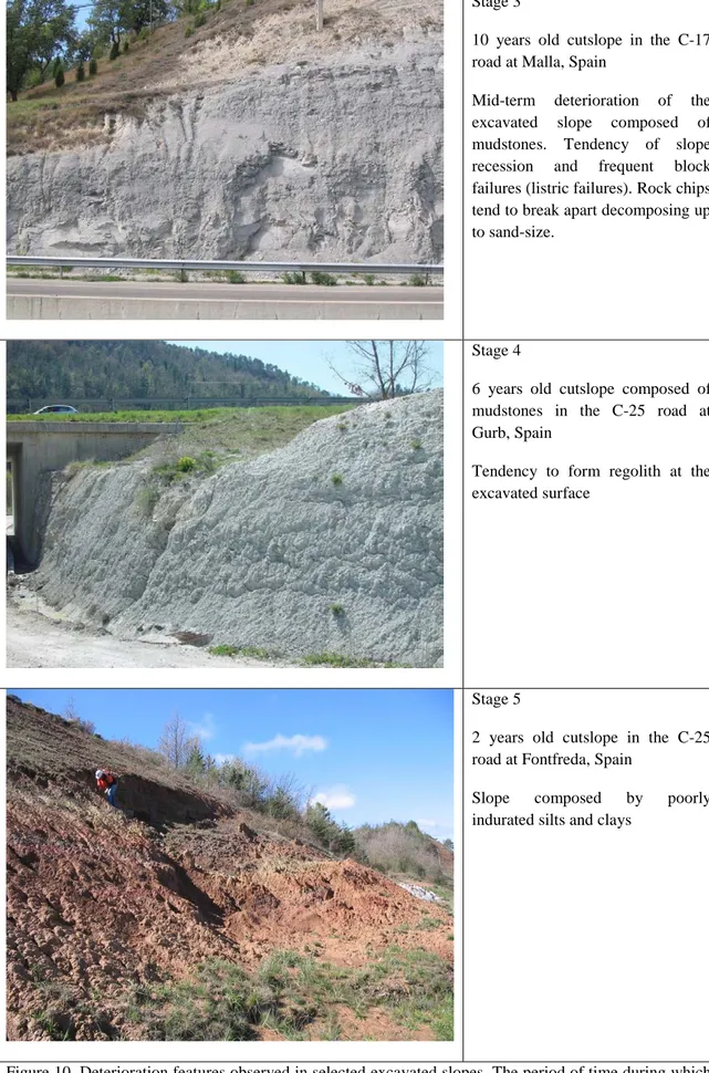
Stage 3
10 years old cutslope in the C-17 road at Malla, Spain
Mid-term deterioration of the excavated slope composed of mudstones. Tendency of slope recession and frequent block failures (listric failures). Rock chips tend to break apart decomposing up to sand-size.
Stage 4
6 years old cutslope composed of mudstones in the C-25 road at Gurb, Spain
Tendency to form regolith at the excavated surface
Stage 5
2 years old cutslope in the C-25 road at Fontfreda, Spain
Slope composed by poorly indurated silts and clays
Figure 10. Deterioration features observed in selected excavated slopes. The period of time during which
362
these deterioration features are generated reduces from Type 1 to Type 5.
363
17
• Stage 1: Intact cutslope. Blast holes are fully visible. Intact or virtually intact excavated slope
365
surface. The slope is stable and only sporadic rockfalls occur.
366
• Stage 2: Slightly weathered slope surface. Fissures and spheroidal exfoliation cracks may appear
367
after some years. It is an overall stable slope. Local (small size) rockfalls occur associated to
368
scattered listric joints. Blast holes are observable for most of the length. The original profile of
369
the excavated slope is kept in average. Unweathered rock chips of a few centimeters in length
370
may accumulate at the bottom of the slope
371
• Stage 3. Weathered slope surface. The excavated surface loses the rocky appearance with time.
372
Spalling and disintegration of the rock surface takes place in less than 10 years. Blast holes are
373
poorly preserved. Frequent small size slides and falls occur through listric joints (curved)
374
generated after the excavation. Debris starts accumulating at the slope foot. The accumulated
375
material decomposed up to sand size and rarely to smaller sizes. Generally overall stable but
376
receding slope.
377
• Stage 4. Heavily weathered slope surface. Intense slaking of the rock surface and tendency to
378
form regolith. Continuous slaking and falling of chunks prevents the slope from rock falls.
379
Weathered rock surface (regolith) may reach depths of some decimeters (figure 11). Original
380
rock structure cannot be recognized. Blast holes have virtually disappeared. Erosion and gullying
381
of the slope surface. Fallen debris easily decomposes to silt-clay size fragments. Receding slope
382
profile. Steep slopes tend to be unstable.
383
• Stage 5. Slope composed of poorly indurated silt and clay. The original rock color has vanished.
384
Weathering and cracking of the rock reach depths of more than 25 cm. Steep slopes are unstable
385
with frequent rotational failures. Gullying develops even with low slope angles.
386
In this description, the slope failures generated along pre-existing joints in the rock mass were not
387
considered as rock deterioration features.
388
389
Figure 11. Gully of more than 20cm depth in the regolith developed on the surface of a 6-years old
390
excavated slope of the C-25 road at Gurb, Spain (stage 4)
391
18
392
393
Seventy-two rock samples were collected from forty-three excavated slopes. The samples were extracted
394
with a portable drilling machine. Cores of 30 mm diameter and 30 cm length were obtained and sent to
395
the laboratory for mineralogical and textural characterization. For the selection of the slopes and the rock
396
samples we took into account several factors: (i) presence of either marine or continental formations; (ii)
397
lithological variety such as mudstones, marls, and shales, in order the assess the influence of the
398
mineralogical and textural components; (iii) absence or a low degree of structural deformation of the
399
layers and whenever possible, the presence of expandable clays to avoid the inclusion of factors that may
400
generate additional scattering in the assessment of the durability of the materials.
401
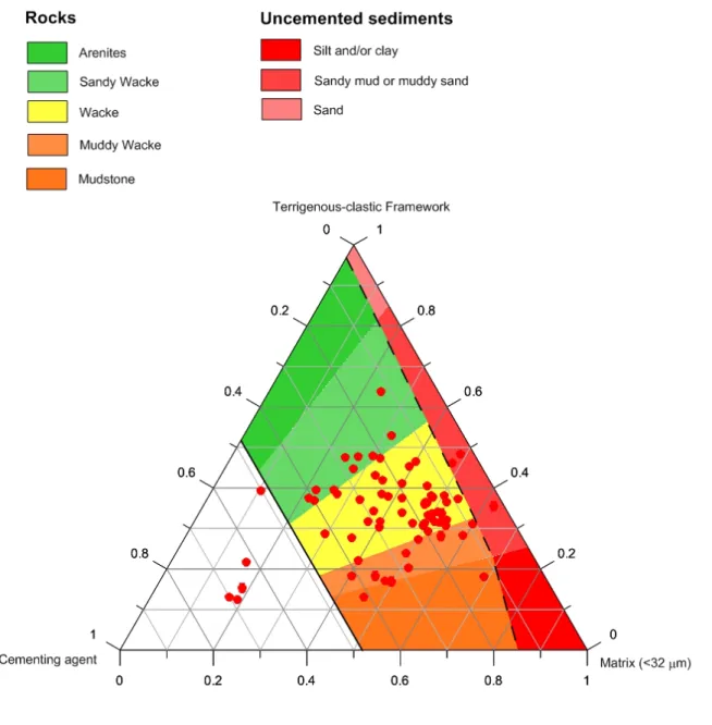
The samples cover a wide range of argillaceous rock compositions and the results are presented in Figure
402
12. As mentioned above, the procedure to quantify the textural components is subjected has some of
403
uncertainty due to of the assumptions made for the quantification of the cementing agent. Therefore, the
404
mineralogical content has been replicated by performing a semi-quantitative Rietveld analysis by X-ray
405
powder diffraction (Martínez-Bofill, 2011). It is noticeable that despite most of the samples having been
406
classified in the field as mudstones and shales only a few of them fulfill the requirement of having more
407
than 75% of fine-grained constituents.
408
19
409
Figure 12. Textural content of the collected samples using the classification scheme proposed in this
410
paper
411
412
The main textural feature that can be identified at first sight during the microscope observation or even at
413
nude eyesight in the counterlight is the homogeneity. Samples may be homogeneous or heterogeneous
414
(Martínez-Bofill et al. 2008): homogeneous textures are characterized by a regular and uniform
grain-415
size and matrix distribution, without remarkable disturbing signs (Figure 13). Conversely, heterogeneous
416
textures show a pattern of different types of textures and grain-size distribution (Figure 14).
417
20
418
Figure 13. Homogeneous texture in thin section: wacky texture, composed of sand-sized quartz grains
419
with fine-grained cemented matrix
420
421
422
Figure 14. Heterogeneous texture in thin section: heterogeneous muddy- predominant texture.
423
The most distinctive features that classify homogeneous textures are grain-size distribution that can be
424
coarse (sandy) or fine (muddy), or presence of fine matrix between coarse clasts (wacky). Fine grained
425
matrix can be bonded either by micrite or sparite crystals or both. Matrix may also be indurated but
not-426
cemented, composed by silt and clay without carbonate cement. The heterogeneous textures are
427
characterized by the presence of clusters of either coarse grains or fine grained-matrix
428
All the samples were tested using a standard slaking test to characterize their durability. The procedure
429
followed was the Slake Durability Test (Franklin and Chandra, 1972) up to five cycles (Figures 15 and
430
16, and table 2).
431
21
432
Figure 15. Two-cycle Slake Durability Index (SDI) of rock samples taken from cut slopes showing
433
different deterioration stages (Fig. 10).
434
435
Figure 16. Five-cycle Slake Durability Index (SDI) of rock samples taken from cut slopes showing
436
different deterioration stages (Fig. 10).
437
438
Samples extracted from cut slopes classified as deterioration stages 1 and 2 have homogeneous coarse and
439
sandy wacke texture and display a Slake Durability Index (SDI) higher than 90% for the two-cycle test.
440
These samples correspond to wackestones, with a high content of sandy grains and, commonly, a
grain-441
supported texture, and carbonate bonding. Conversely, samples displaying two-cycle SDI smaller than
442
22
60% were obtained from cut slopes with deterioration stages 4 or 5. These samples correspond to rock
443
with both homogeneous and heterogeneous muddy textures (Martínez-Bofill et al. 2008).
444
Sample Two cycle SDI Five cycle SDI Cut Slope Stage Sample Two cycle SDI Five cycle SDI Cut Slope Stage A-2.1 m1 2,1 0,0 5 C-25.5 m2 95,9 91,9 3 A-2.1 m2 5,7 0,0 5 C-25.7 m1 61,2 28,6 5 A-2.3 94,4 89,5 4 C-25.7 m2 85,0 60,9 5 A-2.5 84,8 72,6 4 C-25.9 93,4 78,6 4 A-2.6 97,6 94,5 4 C-55.1 m1 99,0 98,2 2 A-2.7 89,5 77,7 4 C-55.1 m2 94,9 89,5 3 A-2.8 93,4 79,1 4 C-55.1 m3 80,4 48,9 4 A-2a.2 82,6 65,0 4 L-301.1 m1 70,3 42,1 5 C-154.1 m1 98,6 96,7 3 L-301.2 m1 91,2 84,0 3 C-16.1 m1 96,2 91,6 4 L-301.2 m2 96,6 93,0 3 C-16.2 96,9 94,3 4 C-16.1 m2 99,1 98,5 1 C-16.3 94,3 88,1 4 C-16.8 88,2 74,2 4 C-16.4 m1 55,4 22,1 5 C-25.6 93,6 81,9 4 C-16.4 m2 77,1 48,3 4 C-25.8 84,0 46,1 4 C-16.4 m3 96,1 91,8 2 IM-2 97,3 94,1 3 C-16.6 55,1 27,2 5 IM-3 97,5 94,1 3 C-16.7 85,5 70,6 4 IM-5 95,8 90,6 3 C-17.1 98,6 96,8 3 IM-6 96,9 93,5 3 C-17.2 97,7 95,0 3 IM-8 96,2 91,9 4 C-17.3 98,9 97,4 3 IM-9 92,9 86,7 3 C-17.4 95,9 87,7 3 IM-11 92,0 88,1 3 C-17.5 97,7 94,2 3 IM-12 95,5 91,7 3 C-25.1 94,7 86,5 4 IM-13 92,7 77,8 3 C-25.10 78,0 62,0 4 IM-15 98,0 96,7 323
C-25.11 11,1 8,4 5 IM-16 97,4 95,3 3 C-25.12 m1 86,8 72,9 4 IM-17 98,9 98,2 2 C-25.12 m2 94,2 89,0 4 IM-18 94,3 84,8 4 C-25.13 98,3 96,9 3 OM-2 91,4 82,6 3 C-25.14 m1 99,2 98,5 2 OM-5 91,8 84,0 3 C-25.15 m1 98,2 96,2 2 OM-6 97,9 95,7 3 C-25.16 79,8 50,5 4 OM-8 97,2 93,8 3 C-25.17 10,5 1,2 5 OM-9 97,5 93,9 3 C-25.2 96,2 88,8 3 OM-10 94,4 88,7 3 C-25.3 98,5 96,8 2 OM-12 97,8 95,7 3 C-25.4 m1 55,9 16,3 4 OM-13 95,9 92,0 3 C-25.4 m2 97,1 94,7 3 OM-15 96,3 91,7 3 C-25.5 m1 77,9 55,3 4 OM-18 99,3 98,6 2 OM-19 97,6 93,3 3Table 2. Two-cycle and five-cycle Slake Durability Indexes (SDI) of samples collected in the studied cut
445
slopes and their deterioration stages
446
447
However, Figs 15 and 16 show that no unique SDI range of values can be assigned to a specific
448
deterioration stage. Despite the fact that several classification schemes consider those rocks displaying
449
two-cycle SDI over 80 as durable rocks (Franklin and Dusseault, 1989; Sadisun et al. 2005; Santi, 2006),
450
in our study area high SDI values do not guarantee the presence of intact slopes on the mid-long term. In
451
fact, two thirds of the tested samples yielded two-cycle SDI over 80%. Figure 15 shows that samples
452
extracted from cuts with deterioration stages 3 and 4 have yielded two-cycle SDI values ranging from
453
98.9 to 91.2 and 97.6 to 77.1, respectively. High values (>90%) of the SDI may also be found in cuts with
454
deterioration stages 1 to 4, indicating that in the study area, the SDI is unable to adequately predict
455
whether any particular slope will evolve towards deterioration stage 3 and 4, or it will remain
456
unweathered. Such a lack of sensitivity of the two-cycle SDT to the rock durability (here, to the cut slope
457
behaviour) has been observed by several researchers (Taylor, 1988; Moon and Beattie, 1995; Gökçeoglu
458
et al 2000; Erguler and Shakoor, 2009).
459
Finally, the cut slope degradation stages have been contrasted against the textural composition of their
460
exposed argillaceous rocks. The results have been split considering homogeneous and heterogeneous rock
461
textures respectively (Figures 17 and 18).
462
24
463
Fig. 17. Distribution of samples showing homogeneous texture from the analyzed cutslopes and their
464
association to the slope deterioration stages (Fig. 10) plotted on the classification scheme proposed in this
465
paper.
466
25
467
Fig. 18. Distribution of the samples showing heterogeneous texture from the analyzed cutslopes and their
468
relation to the slope deterioration stages (Fig. 10) plotted on the classification scheme proposed in this
469
paper.
470
Slopes excavated in sandy wackes consistently show few deterioration features while the slopes
471
excavated in mudstones and muddy wackes deteriorate easily and are highly erodible and unstable. In that
472
respect, the texturally homogeneous argillaceous rocks (Figure 17) show a contrasting response and a
473
reasonable correspondence with the deterioration stage of the excavated slopes. Texturally heterogeneous
474
slopes (Figure 18) display a higher degradability for similar textures. It is suggestive that heterogeneity,
475
and particular the uneven distribution of the grain favours on one hand, the existence of preferential flow
476
paths (high connected porosity or permeability) of the weathering agents and on the other hand, the
477
inability of the cementing agents for accessing the fine-grained clusters.
478
In figure 17, two samples composed of about 80% of total calcium carbonate were studied further to find
479
a more in-depth explanation. As mentioned in the previous section, the main assumption in the procedure
480
followed is that all the carbonate content of the fine-grained matrix is a cementing agent. Figure 19 is an
481
image obtained with a Scanning Electron Microscope with Energy Dispersive X-ray Spectroscopy. It
482
shows well developed dolomite crystals mostly ranging between 2 and 12 µm in size. These crystals have
483
26
replaced previously existing calcite crystals, reaction that produces a reduction of the volume with the
484
subsequent loss of the effectiveness of the bonding action.
485
486
487
Figure 19. Scanning Electron Microscope image of well-developed dolomite crystals (Dol) surrounding a
488
crystal of phyllosilicate (Filo). This image is from one of the samples shown in the lower left-edge
489
(labeled with number 4) in Figure 11.
490
This case shows that while the proposed classification scheme provides a good indicator of likely road cut
491
performance there are additional factors that can influence the actual performance.
492
One must take into account that the excavation process disturbs the rock mass by releasing confinement
493
and causing expansive recovery (Gerber and Scheidegger, 1969; Nichols, 1980) and exposes it to the
494
environmental conditions particularly to moisture and temperature changes. Other well-known factors
495
such as the connected porosity, presence of the expansive or soluble minerals, which have been identified
496
as influencing durability, have not been considered in the classification. Therefore, it will require further
497
analysis and development. Despite of this, texturally-homogeneous argillaceous rocks have shown a
498
satisfactory correspondence with the long-term performance of the excavated slopes.
499
The analysis of the Figures 17 and 18 also highlights that the relationship between cement content and
500
durability is complex. Surprisingly, changes in the cement content of the rocks per se are not reflected in
501
the nature and quantity of deterioration features observed in the excavated slopes. Figure 17 shows that
502
the increase in content of the calcium carbonate cement within the different types of wackestones does
503
not result in an increase of the durability of the corresponding excavated slope. On the other hand, Figure
504
17 suggests that it is the ratio between the clastic framework and the fine-grained matrix that actually
505
controls the durability of the argillaceous rocks.
506
27
Based on this, we interpret that the effectiveness of the bonding between particles depends on the amount
507
of matrix and, particularly on the content of phyllosilicate minerals (clay minerals, mica minerals,
508
chlorite). The efficacy of the cementing agent in sandstones and sandy wackestones for creating strong
509
bonds between the grains is high. This is because the bond is generated as grain-to-grain connection. In
510
wackestones, muddy wackestones and mudstones the matrix content (i.e. phyllosilicates) is high. In this
511
case bonding takes place between grains of the clastic framework, phyllosilicate minerals or between
512
both. Degradation of the argillaceous rock may occur by splitting apart sheets of the phyllosilicate
513
minerals through their exfoliation planes (Figure 20) which are held to one another by weak residual
514
forces, Van der Waals, hydrogen bonds and cations (Thorez, 1975; Weaver, 1989). In this case, rock
515
deterioration can only be prevented by a cementing agent able to generate effective bonds between the
516
grains of the clastic framework and/or around the phyllosilicate minerals.
517
518
Figure 20.Interpretative sketch of the rock disaggregation. Left: sand-size calcite crystals (yellow)
519
bonding both clasts (white) and phyllosilicates (green); Right: disaggregation of the rock is facilitated by
520
the presence of weak phyllosilicate layers bonds
521
FINAL REMARKS
522
Several researchers agree on that the texture and the mineralogical composition of the argillaceous rocks
523
are critical parameters controlling their durability (i.e. Gökçeoglu et al. 2000; Sadisun et al 2005). These
524
two components condition the effectiveness of the weathering processes in changing the intrinsic
525
characteristics of the argillaceous rocks such as the mineralogy, porosity, particle cohesion and the
526
development of microfractures. Other parameters such as the geological history (degree of fracturing,
527
stresses) and the stress release mechanisms must also exert a strong influence (Cripps & Czerewecko,
528
2006).
529
The textural-based classification scheme of the argillaceous rocks presented here aims at effectively
530
accounting for the texture and unlike other classification schemes, the cementing agent has been
531
considered. Three components form the basis for the classification: the clastic framework, the
fine-532
grained matrix and the cement content.
533
To implement this classification either quantitative petrographical or mineralogical analysis is required to
534
determine the textural components. In the samples analyzed in the study areas in Spain, petrographic
535
analysis using an optical microscope and supported with semi-quantitative Rietveld mineralogical
536
analysis based on X-ray powder diffraction have yielded consistent results. These procedure might appear
537
time-consuming and expensive for the durability analyses of the rock. However, this drawback is not
538
more restrictive than other mechanical analysis (i.e. UCS, triaxial tests) routinely performed in
539
engineering projects.
540
28
The analysis of the behavior of the argillaceous rocks in different excavated slopes in Spain shows that
541
road cuts in sandy wackes consistently show few deterioration features while the slopes excavated in
542
muddy wackes and mudstones deteriorate easily, are highly erodible, and produce frequent falls.
543
Texturally homogeneous sandy wackes, wackes and muddy wackes, are mostly associated with slope
544
deterioration stages 2, 3, and 4-5, respectively.
545
The relationship between the cement content and the durability of the rock is complex. We have found
546
that deterioration is mainly prevented by bonding of the grains of the clastic framework. The increase of
547
matrix content and, particularly the presence of phyllosilicate minerals, makes bonding inefficient.
548
Because of this, we conclude that the ratio between the clastic framework and the fine-grained matrix
549
exerts a strong control on the durability of the argillaceous rock. The increase of cementing agent beyond
550
a certain amount does not result in an improvement of the durability.
551
Argillaceous rocks showing heterogeneous textures are less durable. We interpret that heterogeneity
552
favours the existence of preferential flow paths where the weathering agents can penetrate more easily
553
and the presence of fine-grained clusters where the cementing agents are less effective.
554
The proposed classification scheme provides a good first order estimate of the long-term behaviour of
555
argillaceous rock cuts but there are still shortcomings that need to be improved. There are a variety of
556
factors that are not included as the presence of either expansive or soluble minerals, the stress history of
557
the rock, the effect of textural heterogeneity, among others. The influence on durability of the different
558
types of cementing agents (calcite, silica, iron oxide, etc.) also has to be considered in future
559
investigations
560
In the study area the proposed classification scheme performs more satisfactorily than the two-cycle SDT
561
in assessing the potential of the slopes to deterioration. Rock samples having two-cycle SDT values
562
higher than 90% may are associated to cuts showing a wide range of deterioration stages (from stage 2 to
563
4).564
REFERENCES565
566
Alonso EE, Pineda JA (2006). Weathering and degradation of shales: experimental observations and
567
models of degradation. VIth South American Conference on Rock Mechanics, Cartagena de
Indias-568
Colombia. Colmenares & Montero Eds., pp. 249-296
569
570
ACI-American Concrete Institute. (1997). State-of-the-Art Report on Soil Cement. ACI230.1R-90
571
572
Bish DL, Post JE (1989). Modern Powder Diffraction, MSA Reviews in Mineralogy 20, Washington,
573
Mineralogical Association of America, 384 p.
574
575
Blatt H (1982). Sedimentary petrology: WH Freeman and Company, San Francisco, 564 pp.
576
577
Bjerrum L (1967) Progressive failure in slopes of overconsolidated plastic clay and clay shales. J.Soil
578
Mech. & Found. Division, ASCE, Vol 93, pp.3-49.
579
580
Calcaterra, D, Parise M (2010). Weathering as a predisposing factor to slope movements: an introduction.
581
In D. Calcaterra & M. Parise (Eds.). Weathering as a predisposing factor to slope movement. Geological
582
Society, London, Engineering Geology Special Publication 23:1-4. DOI: 10.1144/EGSP23.1
583
584
Cripps JC, Czerewko MA (2006). The implications of diagenetic history and weathering on the
585
engineering behaviour of mudrocks. In 10th Congress of the International Association of Engineering
586
Geology and the Environment, Nottingham.
587
588
Chandler RJ (2010). Stiff sedimentary clays: geological origins and engineering properties,
589
Géotechnique, 60: 891-902
590
591
Conway JA, Sloane NJA (1993). Sphere packings, lattices and groups. Springer-Verlag. New York.
592
29
593
Dick JC, Shakoor A (1997). Predicting the durability of mudrocks from geological characteristics of
594
mudrocks: in Santi, P. and Shakoor, A., eds., Assoc. Eng. Geol., Special Publication No. 9, pp. 89-105
595
596
Dott RH (1964). Wackstone, graywacke and matrix = what approach to inmature sanstone classification?.
597
Journal of sedimentary petrology. Num 34. 625-632 pp
598
599
Erguler ZA, Shakoor A. (2009). Quantification of fragment size distribution of clay-bearing rocks after
600
slake durability testing. Environmental and Engineering Geoscience 15: 81-89
601
602
Erguler ZA, Ulusay, R. (2009). Assessment of physical disintegration characteristics of clay-bearing
603
rocks: disintegration index test and a new durability classification chart. Engineering Geology, 105: 11-19
604
605
Folk RL (1954). The distinction between grain size and mineral composition in sedimentary rock
606
nomenclature: Journal of Geology, 62: 344-359.
607
608
Folk RL (19809. Petrology of sedimentary rocks: Austin, Texas, Hemphill’s Bookstore, 170 pp.
609
610
Franklin JA, Chandra R (1972). The slake durability test. International Journal of Rock Mechanics and
611
Mining Science & Geomechanics Abstracts, 9, 325-328.
612
613
Franklin JA (1983). Evaluation of Shales for Construction Projects: an Ontario shale rating system.
614
Report RR29 Research and Development Branch. Ministry of Transportation and Research. Toronto
615
616
Franklin JA, Dusseault MB (1989). Rock Engineering. Mc Graw Hill Inc. New York. 600pp.
617
618
Gens A (2013). On the hydromechanical behaviour of argillaceous hard soils-weak rocks. Proceedings of
619
the 15th European Conference on Soil Mechanics and Geotechnical Engineering – Geotechnics of Hard
620
Soils – Weak Rocks (Part 4). A. Anagnostopoulos et al. (Eds.). IOS Press. pp. 71-118
621
622
Gerber E, Scheidegger AE (1969). Stress-induce weathering of rock masses. Eclogae Gelogicae Helvetiae
623
62: 401-416
624
625
Gökçeoglu C, Ulusay R, Sönmez H (2000). Factors affecting the durability of selected weak and
clay-626
earing rocks from Turkey, with particular emphasis on the influence of the number of drying and wetting
627
cycles. Engineering Geology 57: 215-237
628
629
Grattan-Bellew PE, Eden W J. (1975). Concrete deterioration and floor heave due to biogeochemical
630
weathering of underlying shale. Canadian Geotechnical Journal, 12: 372 - 378.
631
632
Hallsworth CR, Knox RWO’B (1999). BGS Rock Classification Scheme. Volume 3. Classification of
633
sediments and sedimentary rocks. British Geological Survey. Research Report number rr 99-03.
634
Nottingham UK. 44 pp.
635
636
Hawkins AB (2000). General Report: The nature of hard soils/soft rocks, The Geotechnics of Hard Soils
637
– Soft Rocks (A. Evangelista, L. Picarelli, eds.) Balkema, Rotterdam. Vol.3: 1391-1402
638
639
Johnston IW, Novello EA (1993). Soft rocks in the geotechnical spectrum, Geotechnical Engineering of
640
Hard Soils-Soft Rocks (A. Anagnostopoulos et al., eds.),
641
Balkema, Rotterdam. Vol.1: 177-183.
642
643
Kornprobst J (2003) Metamorphic rocks and their geodynamic significance. A petrological handbook.
644
Kluwer Academic Publishers. 205 pp.
645
646
Krynine PD (1948), The megascopic study and field classification of sedimentary rocks: Journal of
647
Geology, 56:130-165
648
649
Marinos PG (1997). General Repot Session 1: Hard soils – soft rocks: Geological features with special
650
emphasis to soft rocks, Geotechnical Engineering of Hard Soils- Soft Rocks (A. Anagnostopoulos et al.,
651
eds.), Balkema, Rotterdam. Vol. 3: 1807-1826
652
30
653
Martinez-Bofill J, Corominas J, Soler A (2004). Behaviour of the weak rock cutslopes and their
654
characterization using the results of the Slake Durability Test. In Lecture Notes in Earth Sciences. 104.
655
Engineering Geology for Infrastructure Planing in Europe, pp. 405-413.
656
657
Martinez-Bofill J, Corominas J, Soler A (2008). Analysis of the relationship between durability and
658
petrological characteristics of weak rocks. Euroengeo. Proceedings of the II European Conference of
659
International Association for Engineering Geology. Madrid
660
661
Martinez-Bofill J (2011). Alterabilidad de limolitas, arcillitas y margas. Aplicación a la estabilidad de
662
desmontes y excavaciones. PhD Thesis. Universitat Politèccnica de Catalunya. 427 pp.
663
664
Mitchell JK (1993). Fundamentals of soil behavior. John Wiley & Sons, New York. 437 pp.
665
666
Moon VG, Beattie AG (1995). Textural and microstructural influences on the durability of Waikato coal
667
measures mudrocks. Quaterly Journal of Engineering Geology, 28: 303-312
668
669
Morgenstern N (1974). Classification of Argillaceous Soils and Rocks. Journal of the Geotechnical
670
Engineering Division, Vol. 100 (10): 1137-1156
671
672
Nichols TC (1980). Rebound its nature and effect on engineering works. Quaterly Journal of Engineering
673
Geology, 13: 133-152
674
675
Nicholson DT (2004). Hazard assessment for progressive, weathering-related breakdown of excavated
676
rockslopes. Quarterly Journal of Engineering Geology and Hydrogeology, 37, 327–346
677
678
Nickmann M, Spaun G, Thuro K (2006). Engineering geological classification of weak rocks. In 10th
679
Congress of the International Association of Engineering Geology and the Environment, Paper number
680
492, Nottingham
681
682
Nickmann M, Sailer S, Ljubesic J, Thuro K (2010). Engineering geological investigations into the border
683
between hard and weak rocks. Geologically Active – Williams et al. (eds). Taylor & Francis Group,
684
London. pp. 2265-2272
685
686
Pettijohn FJ, Potter PE, Siever R. (1972). Sand and Sandstone. Springer-Verlag, Nueva York, 618 pp
687
688
Pineda JA, Alonso EE, Romero R (2014). Environmental degradation of claystones. Geotechnique, 64:
689
64-82
690
691
Potter PE, Maynard JB, Depetris PJ (2005). Mud and mudstones. Springer-Verlag, Berlin. 308 pp.
692
693
Potts PJ (1992). X-ray fluorescence analysis: principles and practice of wavelength dispersive
694
spectrometry. In Potts PJ (Ed) Handbook of silicate rock analyses. p. 226-285
695
696
Quigley RM, Vogan RW (1970). Black shale heaving at Ottawa, Canada. Canadian Geotechnical Journal,
697
7: 106-112
698
699
Russell DJ (1981). Controls on shale durability: the response of two Ordovician shales in the slake
700
durability test. Canadian Geotechnical Journal,19: 1-13,
701
702
Sadisun IA, Shimada H, Ichinose M, Matsui K. (2005). Study on the physical disintegration
703
characteristics of Subang claystone subjected to a modified slaking index test. Geotechnical and
704
Geological Engineering, 23: 199-218.
705
706
Santi P (1998). Improving Jar Slake, Slake index, and Slake Durability Tests for shales. Environmental &
707
Engineering Geoscience, 4: 385-396
708
709
Santi P (2006). Field methods for characterizing weak rocks for engineering. Environmental &
710
Engineering Geoscience, 12: 1-11
711
31
Simpson B (2010). Engineering in stiff sedimentary clays. Géotechnique, 60: 903-911.
713
714
Taylor RK (1988). Coal Measures mudrocks: composition, classification and weathering processes.
715
Quarterly Journal of Engineering Geology and Hydrogeology, 21, 85-99.
716
717
Terzaghi K, Peck RB (1967). Soil Mechanics in Engineering Practice. Wiley, New York, 729 pp.
718
719
Terzaghi K, Peck RB, Mesri G (1996). Soil Mechanics in Engineering Practice, 3rd ed., John Wiley &
720
Sons, New York. Winterkorn, 549 pp.
721
722
Thorez J (1975). Phyllosilicates and Clay Minerals: A laboratory handbook for their X-Ray diffraction
723
Analysis. G. Lelotte. California University. 579 pp.
724
USACE (1994). Soil Stabilization for Pavements. Joint Departments of the Army and Air Force, USA,
725
TM 5-822-14/AFMAN 32-8010
726
U.S. Geological Survey, USGS, (2004). North American Geologic-Map Data Model Science Language
727
Technical Team, 2004b, Report on progress to develop a North American science-language standard for
728
digital geologic-map databases; Appendix C1 – Sedimentary materials: Science language for their
729
classification, description, and interpretation in digital geologic-map databases; Version 1.0 (12/18/2004),
730
in Soller, D.R., ed., Digital Mapping Techniques ’04—Workshop Proceedings: U.S. Geological Survey
731
Open-File Report 2004-1451, 595 p. Appendix C1 accessed at
732
http://pubs.usgs.gov/of/2004/1451/sltt/appendixC/appendixC_pdf.zip.
733
Ward CR, Nunt-jaruwong S, Swanson J. (2005). Use of mineralogical analysis in geotechnical assessment
734
of rock strata for coal mining. International Journal of Coal Geology, 64: 156-171
735
736
Weaver CE (1989). Clay, muds and shales. Developments in Sedimentology, 44. Elsevier Science
737
Publishers B.V. Amsterdam, The Netherlands. 809 pp.
738
739
Williams H, Turner FJ, Gilbert CM (1982) Petrography, An Introduction to the
740
Study of Rocks in Thin Section: W.H. Freeman and Co., San Francisco, 626p.
741
742
Wood LE Deo P (1975). A suggested system for classifying shale materials form embankments. Bulletin
743
of the Association of Engineering Geologists, 12: 39-55
744
745
Young RA (1993). The Rietveld Method. International Union Crystallography, Oxford University Press,
746
298 p. New York.