Scuola Superiore Sant’Anna
The BioRobotics Institute
PHD IN BIOROBOTICS
A Unified Hierarchical Framework for Motion Planning and Control
of Anthropomorphic Robotic Manipulators: an Intended Application
of Physical Human-Robot Interaction to Rehabilitation
Ali Leylavi Shoushtari
2017
Tutor: Prof. Paolo Dario
Supervisor: Dr. Stefano Mazzoleni
1
A Unified Hierarchical Framework for Motion Planning and
Control of Anthropomorphic Robotic Manipulators: an Intended
Application of Physical Human-Robot Interaction to
Rehabilitation
By:
Ali Leylavi Shoushtari
Submitted to The BioRobotics Institute
in partial fulfillment of the requirements for the degree
Doctor of Philosophy
at the
SCUOLA SUPERIORE SANT’ANNA
May 2017
Tutor: Prof. Paolo Dario
Supervisor: Dr. Stefano Mazzoleni
ABSTRACT
By:Ali Leylavi Shoushtari Submitted to the BioRobotics Institute
On May 2017, in partial fulfillment of the requirements for the Doctor of Philosophy in Biorobotics
SCUOLA SUPERIORE SANT’ANNA
This dissertation is aimed to human-robot interaction design, modeling and validating of compliance control on a 7 DOFs robotic manipulator. This thesis initiates with a systematic literature review on robotic interaction: theoretical and technical aspects of interaction control algorithm are studied and analysed. In this review a critical analysis of the control algorithms developed for robotic interaction tasks is presented. A hierarchical classification of distributed control levels from general aspects to specific control algorithms is also illustrated. Hence, two main control paradigms are discussed together with control approaches and architectures. The challenges of each control approach are discussed and the relevant solutions are presented. Furthermore an evolvement trend of interaction control theories and technologies over time is presented. In addition this dissertation highlights the pros and cons of each control approaches and addresses how the flaws of one control approach were compensated by other control methods. This review can provide the robotic controller designers with useful information on how to select the right architecture and accordingly to design the appropriate control algorithm for any given interactive task and with respect to the technology implemented in a robotic manipulator.
Hence the impedance controllability is recognized as one of the control challenges of interaction control. Safety is another issue to be faced in rehabilitation control which is analysed in two terms: collision avoidance and stability of the controller. To implement these two characteristics, an innovative collision and singularity free redundancy resolution named “Bio-inspired inverse Kinematic (BINIK)” is presented. The algorithm takes advantage of human upper arm-inspired concept of inter-joint dependency to control a 7 DOFs anthropomorphic redundant robotic arm. A mechanism is presented in this dissertation in order to provide the optimal working point of the algorithm. Finally the performance of the algorithm is evaluated by means of a set of kinematical simulations.
In the next two parts of this dissertation the theory of joint space admittance control is presented and a set of rehabilitative tasks are simulated as the intended application of this control. The general idea of this control theory is based on motion planning in trajectory space and performing a control in joint space. So, by applying BINIK a collision-avoided motion is achieved. The stability conditions of the system are obtained through a stability analysis and are applied on controller design. In the fifth chapter, the kinematics and dynamics of a rehabilitation task are analysed based on a set of task/control modalities. Accordingly, dynamic simulation trials are designed with respect to these modalities aimed to simulate activities of daily living and also to evaluate the performance of the controller. The results prove the robot’s compliance modulation capability (which enables robot to work in different modes spanning from stiff to compliant behavior), robustness in presence of harsh interactions as well as safety (including collision avoidance and dynamic stability). The last chapter presents the effects of the body of robot on the physical interaction. Hence a design and fabrication framework is presented to integrate the rigid elements into soft robots. The framework addresses solutions to deal with issues presented in hybrid rigid-soft integration.
2
Acknowledgement
To complete this work, I have received supports and helps from so many persons. I would like to thanks especially to my supervisor, Prof. Dario who first of all, always directly or indirectly encouraged me, and kept me motivated through his advices and lectures. I would thank my co-advisor Dr. Mazzoleni for his supports during these three years. And furthermore, I would appreciate the helps I received from the scientific members of Rehabilitation Bioengineering Laboratory of Auxilium Vitae, Volterra where I’ve carried out my research.
Two papers (Leylavi Shoushtari et al., 2016b, Leylavi Shoushtari et al., 2016a) are published respectively in the Journal of Assembly Automation and Industrial Robots as results of this study. Two more papers have been submitted to journal of Autonomous Robots. These papers are entitled " joint space admittance control of 7 DOFs anthropomorphic manipulator: part I-theory" and "joint space admittance control of 7 DOFs anthropomorphic manipulator: part II-application on robotic rehabilitation". Furthermore, as results of the soft robotic project (in collaboration with Yasmin Ansari and Vito Cacucciolo), two conference papers have been published (Cacucciolo et al., 2015, Ansari et al., 2015) and one more paper is under preparation to be submitted to journal of
Applied Sciences. The paper is entitled “Control of soft-limbed robots using morphological
computation”.
Table of Contents
ABSTRACT ... 1 Acknowledgement ... 2 List of figures ... 5 List of tables ... 7 Chapter 1 Introduction ... 81.1 Robotic interaction control ... 8
1.2 Redundancy resolution ... 9
1.3 Control, motion planning and safety ... 10
1.4 Robotic rehabilitation ... 12
Chapter 2 A systematic review on robotic interaction control ... 15
2.1 Introduction ... 15
2.2 Methods ... 16
2.3 Robotic interaction control ... 18
2.3.1 First control paradigm: control of force and motion ... 19
2.3.1.1 Partitioned control approach ... 19
2.3.1.2 Integrated control approach ... 24
2.3.2 Second control paradigm: control of dynamic behavior ... 28
2.3.2.1 Impedance control ... 29
2.4 Impedance control challenges ... 30
2.4.1. Impedance controllability ... 31
2.4.1.1 Robot-object (passive environment) interaction task ... 31
2.4.1.2 Robot-robot interaction task ... 32
2.4.1.3 Robot-human interaction task ... 32
2.4.1.3.1 Cognitive studies of human motor control... 32
2.4.1.3.2 Robotic neuromotor rehabilitation ... 33
2.4.2 Impedance variability ... 33
2.4.2.1 Actuators ... 34
2.4.2.2 Robot bodyware ... 35
2.5 Conclusions ... 36
Chapter 3 A synergy-based collision-free redundancy resolution ... 40
3.1. Introduction ... 40
3.2. Unified Motion Planning Framework ... 41
3.2.1 Geometric algorithm ... 41
3.2.2 Geometry of the system ... 41
3.2.3 Control algorithm ... 41
3.3. Simulation of planar task ... 45
3.4. Spatial motion planning algorithm ... 50
3.4.1 End-effector 3D positioning ... 50
3.4.2 Modeling and motion control ... 51
3.4.3 Spatial motion simulation results ... 55
3.5. Discussion and conclusion ... 57
Chapter 4 A joint space compliance control approach: theoretical approach ... 59
4.1 Introduction ... 59
4.2 motion planning ... 59
4.3 Compliant control design ... 62
4.4 Safety issues ... 65
4.4.1 Stability analysis ... 65
4
4.5 Discussion and conclusions ... 69
Chapter 5 A joint space compliance control approach: an application on robotic rehabilitation... 71
5.1 Introduction ... 71
5.2 Materials and methods ... 71
5.2.1 Task/motion planning parameters and modalities ... 73
5.2.2 Control parameters and modalities ... 74
5.3 Design of dynamic simulation trials ... 75
5.3.1 Kinematics of trials ... 75
5.3.2 Control and dynamics of trials ... 82
5.4 Results and discussion ... 85
5.4.1 Critical case scenario ...101
Chapter 6 A Robot’s body contribution in interaction control ... 105
6.1 Introduction ... 105
6.2 Design and fabrication ... 107
6.2.1 Flexible fluidic actuator ... 107
6.2.2 Nozzle-tube connection design ... 108
6.2.3 Design of flexible spine ... 110
6.2.4 Integrating the robot and spine ... 111
6.3 Actuator characterization ... 112
6.4 Control ... 113
6.5 Results and discussion ... 114
6.5.1 Results of characterization ... 114
6.5.2 Application on quadrupedal locomotion ... 115
6.5.2.1 Rigid spine ... 116
6.5.2.2 Flexible symmetric spine ... 116
6.5.2.3 Flexible asymmetric spine ... 117
6.6 Conclusion ... 119
Chapter 7 Conclusions and future works ...120
Future works ...122
Bibliography ...123
Appendix A ...132
Appendix B ...133
List of figures
Figure 2-1 The hierarchical classification pyramid of robotic interaction control ... 16
Figure 2-2 Four main steps of the method used to carry out the review ... 17
Figure 2-3 Two control paradigms of robotic interaction task and relevant approaches/architectures ... 18
Figure 2-4 Schematic representation of tele-operation system ... 20
Figure 2-5 The human operator, master robot, controllers and communication channel ... 22
Figure 2-6 The schematics of Multi-Masters/Multi-Slaves architecture ... 22
Figure 2-7 The main challenges that impedance control has encountered ... 23
Figure 2-8 A schematic diagram of hybrid control ... 25
Figure 2-9 The main challenges of impedance as well as control problems/solutions ... 28
Figure 2-10 Target stiffness model of end-effector ... 30
Figure 2-11 The main challenges of impedance control, problems and relevant resolutions ... 36
Figure 3-1 Schematic configuration of the mechanism with n DOFs ... 40
Figure 3-2 The unified computational framework for motion planning of a 4 DOFs robot manipulator ... 41
Figure 3-3 The morphology of the robot is considered as a second order polynomial ... 41
Figure 3-4 The geometric algorithm as a control loop to calculate the position of the robot’s joints ... 42
Figure 3-5 The computational geometric algorithm ... 43
Figure 3-6 The control algorithm designed to regulate the value to reach... 44
Figure 3-7 The predicted postures of the redundant robot ... 45
Figure 3-8 The predicted postures for three paths ... 46
Figure 3-9 The simulation results of P-shape trajectory tracking (4 DOFs). ... 47
Figure 3-10 End-effector tracking errors. ... 48
Figure 3-11 Optimal point analysis flowchart ... 49
Figure 3-12 MAE plotted versus algorithm step size ... 49
Figure 3-13 NRMSE and NCTSP and normalized computational time for single point (NCTSP) ... 50
Figure 3-14 Synergy based control of a 7 DOFs robot. ... 51
Figure 3-15 The 3DOFs cylindrical mode. ... 52
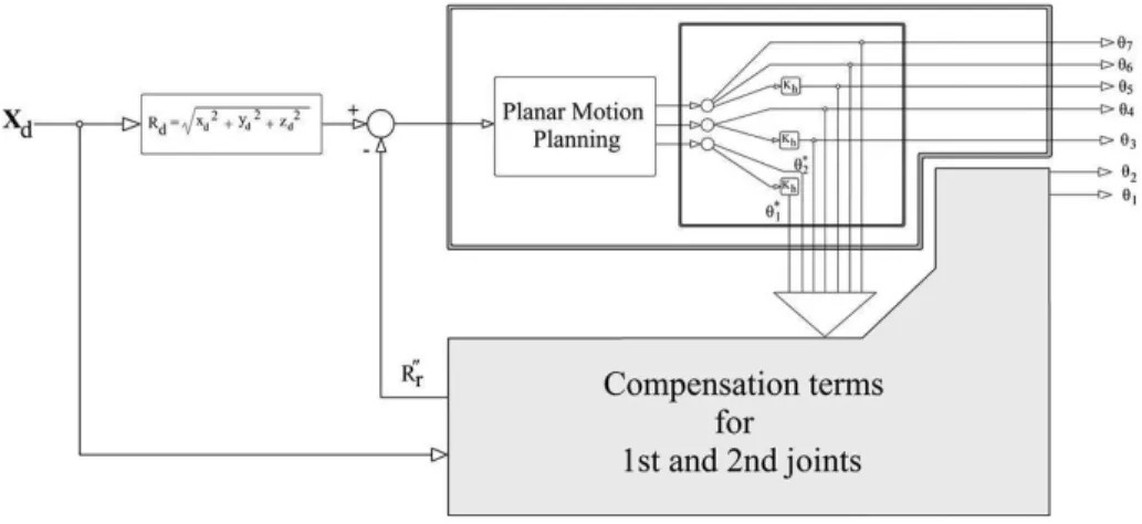
Figure 3-16 Block-diagram representation of the spatial motion planning algorithm ... 52
Figure 3-17 Scheme of planar motion planning algorithm. ... 53
Figure 3-18 Top: “Compensation terms for the first and second joints”. ... 53
Figure 3-19 Optimal point analysis for 3D oval-shape trajectory ... 54
Figure 3-20 Joint analytical angle profiles plotted for 3D oval-shaped trajectory ... 55
Figure 3-21 RMSE plotted for 3D oval-shape task with different values of synergy coefficient ... 56
Figure 3-22 Robot configurations during tracking an “R-shaped”path, error and manipulability ... 57
Figure 4-1 General representation of computed-torque control ... 63
Figure 4-2 Inverse dynamic-based admittance control scheme ... 64
Figure 4-3 The projection flow of external force from human side to robot's joints ... 65
Figure 4-4 Representation of sphere which embeds the ellipsoid ... 66
Figure 4-5 The division of robot and human workspace. ... 68
Figure 4-6 Configurations of robot for four planar trajectories located in different distances from robot. ... 69
Figure 5-1 Hierarchy of motion control trial design ... 72
Figure 5-2 Goals and sub-goals of robotics rehabilitation tasks ... 73
Figure 5-3 Parameters and modalities (black box) of task/motion planning goals ... 74
Figure 5-4 The parameters and modalities of control goals ... 75
Figure 5-5 The schematic view of human-robot in transversal plane for door opening task ... 76
Figure 5-6 Schematic view of door opening task designed in transversal plane ... 77
Figure 5-7 Schematic view of reaching tasks designed in sagittal ... 78
Figure 5-8 Schematic view of Reaching task and end-effector tracking the trajectory ... 79
6
Figure 5-10 Schematic view of Window wiping task and robot tracking the trajectory... 80
Figure 5-11 Schematic view of spatial spiral task ... 81
Figure 5-12 Schematic view of the spiral-shaped task and end-effector trajectory designed in space ... 81
Figure 5-13 The resulted deviation of end-effector in Normal-Bi-normal plane ... 85
Figure 5-14 The joint torques corresponded to the smooth-firm (left) and smooth-loose (right) trials ... 86
Figure 5-15 The joint torques corresponded to the Jerky &Firm (left) and Jerky & Loose (right) trials ... 87
Figure 5-16 End-effector traces for the "reaching" tasks for stiff (left) and compliant(right)modes. ... 88
Figure 5-17 The robot traces for "window wiping" tasks for stiff (left) and compliant (right)modes ... 88
Figure 5-18 The end-effector traces for "Door opening" tasks for stiff (left) and compliant (right) modes .... 89
Figure 5-19 The end-effector traces for the "Spiral" tasks for stiff (left) and compliant (right) modes ... 89
Figure 5-20 The end-effector stiffness profile in TNB ... 91
Figure 5-21 The end-effector stiffness profile in TNB for reaching task (Direct reaching) ... 92
Figure 5-22 The end-effector stiffness profile in TNB for Window wiping task (Near case) ... 93
Figure 5-23 The end-effector stiffness profile in TNB for Window wiping task (Mid case) ... 94
Figure 5-24 The end-effector stiffness profile in TNB for Window wiping task (Mid case) ... 95
Figure 5-25 The end-effector stiffness profile in TNB for Door opening task ... 96
Figure 5-26 The end-effector stiffness profile in TNB coordinate system for Spiral task ... 97
Figure 5-27 The end-effector velocity profile in TNB coordinate system for reaching task (obs. avoid.) ... 98
Figure 5-28 The end-effector velocity profile in TNB coordinate system for Reaching task (Direct case) ... 98
Figure 5-29 The end-effector velocity profile in TNB coordinate system for Window wiping task (Near) ... 99
Figure 5-30 The end-effector velocity profile in TNB coordinate system for Window wiping task (Mid) ... 99
Figure 5-31 The end-effector velocity profile in TNB coordinate system for Window wiping task (Far) ...100
Figure 5-32 The end-effector velocity profile in TNB coordinate system for Door opening task ...100
Figure 5-33 The end-effector velocity profile in TNB coordinate system for Spiral task ...101
Figure 5-34 The end-effector velocity profile in TNB coordinate system for Spiral task in CCS ... 101
Figure 5-35 The end-effector stiffness profile in TNB coordinate system ...102
Figure 5-36 The resulted deviation of end-effector in Normal-Binormal plane. ...102
Figure 5-37 The end-effector trajectory for critical case scenario ...103
Figure 5-38 The joint torque profiles for critical case scenario ...104
Figure 6-1 The possibility space of impedance-based control approach for both soft and rigid robots... 105
Figure 6-2 Bending motion as a result of pressurizing the developed anisotropic FFA... 107
Figure 6-3 Fabrication steps of our version of flexible fluidic actuators ... 108
Figure 6-4 Bi-functional nozzle ... 108
Figure 6-5 Cross-section of the mold ... 109
Figure 6-6 Different clamp-based connections ... 110
Figure 6-7 CAD design of the flexible spine ... 111
Figure 6-8 Fully assembled robot with dimensions ... 111
Figure 6-9 a. FASTT Robot. b. the leg motion in sagittal plane. c. the robot motion in transversal plane ... 112
Figure 6-10 Experimental method used to measure the force exerted by the actuator ... 113
Figure 6-11 Actuation pattern for bounding gait according to Hildebrand ... 113
Figure 6-12 Experimental set-up. ... 114
Figure 6-13 Angle-pressure and force-pressure characterization of the fluidic actuator ... 114
Figure 6-14 (Left) rigid spine (center) symmetric spine (right) asymmetric spine ... 116
Figure 6-15 Angular displacement for asymmetric spine for ( = 40⁰, =-20⁰)... 117
Figure 6-16 Schematic view of asymmetric and symmetric spine when front legs are actuated ... 118
Figure B-1 The values for absolute error and relative error for critical case scenario ...133
List of tables
Table 2-1 The coefficients of control inputs implemented in controller's equation ... 21
Table 2-2 A List of control challenges, problems and resolutions ... 38
Table 3-1 The parameters of algorithm used for fourfold trajectories ... 44
Table 3-2 The values of polynomial coefficients for joint angle profiles ... 56
Table 4-1 A hierarchy-based approach from motion planning (darkest row) to control... 60
Table 5-1 The interaction force modalities: designed for the spiral trajectory ... 82
Table 5-2 The modalities of the tangential velocity designed for entire all trajectories ... 83
Table 5-3 The modalities of the impedance designed for entire all trajectories ... 84
Table 5-4 The modalities of critical case scenario designed for spiral-shaped trajectory ... 84
Table 6-1 A summary of results ... 118
Table C-1 Denavit-Hartenberg parameters of the 7 DOFs robot. ... 135
Table C-2 Dynamic parameter of the robot links. ... 135
8
Chapter 1
Introduction
Several critical issues have to be carefully considered when designing a control algorithm for rehabilitation/assistive tasks, such as 1) physical interaction control, 2) safety, and 3)-motion planning. Considering that the robot used in this work is a redundant robotic manipulator, the
redundancy represents an additional issue to be faced with. Hence, in this chapter an extensive
literature review is presented in order to provide the state of the art of the above mentioned issues. In each of following sections one of the above-mentioned issues are presented. The sections are as follow: 1) robotic interaction control, 2) redundancy resolution 3) control, motion planning and safety and finally 4) robotic rehabilitation.
1.1 Robotic interaction control
The interaction is a critical issue in robotics since not only it deals with all aspects of a robot e.g. design of sensors, actuators, body of robot and control, but also it enables robots to carry out extraordinary tasks e.g. exploration the physical features of an object through robotic finger (Dario and Buttazzo, 1987, Dario and Bergamasco, 1988) and robotic colonoscopy (Dario et al., 2004).Achieving such capabilities requires a control system which not only should be consistent with the hardware but also should satisfy all goals of control e.g. stability, adaptation, robustness, safety and of course efficiency. This chapter is aimed to review the robotic interaction control in order to provide a guide for designers of robotic controllers.
In engineering-based research the researchers always are searching for solutions; accordingly they always come up with novel designs, algorithms, methods or development of current methods and designs. While, in addition to finding the right solution, it is also highly required to recognize the right problem to be solved. In other words, it is required to understand well the problem description/statement. To achieve such objective we need to look over the trend of solutions, which would help us to reveal what fundamental question/questions the researchers were trying to answer. Accordingly, by representing two general and fundamental questions, we would design a unified classification over the control algorithms presented for robotic interaction task.
The first fundamental question/problem to be posed about the control of any dynamic task simply is "what element has to be controlled?"
By analyzing the control algorithms for robotic interaction control developed so far, two distinguished sets of answers/solutions have been identified and named as control paradigms. In particular, the "control paradigm" is defined as a "unified theoretical framework which embeds various control approaches, aimed to provide a specific solution to the mentioned problem". These paradigms are: "paradigm of force/motion control" and the "paradigm of dynamic behavior control".
Each robotic control algorithm selects one or a set of variables as control elements e.g. contact force/torque and/or rotational/linear displacement, velocity or acceleration known as motion. The answer to the primary question reveals which elements have to be controlled. Accordingly, the main control elements would be force/motion and dynamic behavior. Within each paradigm a secondary question can be asked in order to reach a practical solution: "How the controller can control the control elements?" The control approaches provide a set of general answers/solutions for the question/problem and the control architectures are the specific practical forms of these answers/solutions.
1.2 Redundancy resolution
Numerous instances of redundancy can be found in biological and artificial systems. One of the most significant is represented by the musculoskeletal structure of human body which can be modeled as a kinematic chain (Khatib et al., 2009). Maneuverability is a consequential feature which allows redundant systems to have dexterous behavior e.g. manipulation. Mechanisms with redundant degrees of freedom (DOFs) are potentially able to perform dexterous tasks. While redundancy provides maneuverability in terms of efficiency, on the other hand it also raises problems in the motion planning.
Over the last decades a growing attention has been paid to redundant robotic manipulators due to the several advantages linked to the exploitation of redundancy, such as safety and maneuverability. Despite the fact, redundancy is often considered as a problem from the control point of view. Several solutions have been proposed to deal with position (Seraji, 1989, Pyung, 1987), velocity (Whitney, 1969, Yoshikawa, 1985) and acceleration (Hollerbach and Suh, 1987). These solutions can be classified into three main categories: 1) linear algebra-based (LAB), 2) soft computing-based (SCB) and 3) bio-inspired approaches (BIO).
The pseudo-inverse is a fundamental method in the LAB category (Siciliano, 1990) which proposes to decouple the joint velocities into two terms associated with the operational space and the null space (Whitney, 1969, Whitney, 1972). The second component is usually addressed for optimizing an arbitrary criterion. The main advantage of this method is to provide the incorporation of a biological-based defined criterion as second term e.g. collision avoidance (Maciejewski and Klein, 1985), minimum joint torques (Chen et al., 1994), task priority (Chiaverini, 1997, Nakamura et al., 1987).
The SCB approaches, including artificial neural networks (ANN), pseudo-inverse network (Wang, 1997) and linear programming neural networks (Xia, 1996), fuzzy logic (Ramos and Koivo, 2002)) and genetic algorithms, generally rely on linear algebraic equations presented in the previous category; consequently the inevitability of the Jacobian matrix which occurs in singular/near-singular points represents an issue to be considered.
The BIO methods provide solutions where the specific strategies that human central nervous system (CNS) employs to control body movements are considered as source of inspiration. The majority of human imitation-based motions planning techniques are based on directly mimicking the human arm posture (Kim et al., 2005) and hand pose (Pollard et al., 2002) (position and orientation). In fact these methods, known as bio-mimetic approaches, aim to imitate the human
10
arm movement (Potkonjak et al., 1998) for robotic motion planning purposes. The task-specification represents the main feature of these approaches, restricting their motion planning capability on the tasks where the data sets were recorded from. In other words, in addition to the ability to generate human-like motion the generalization should also be considered as a mandatory property of a kinematic control for anthropomorphic manipulators.
In contrary of imitation-based approaches, the other BIO methods put emphasis on human movement primitives (Abedi and Shoushtari, 2012). These methods solve kinematic redundancy in human-like fashion by satisfying biological-based defined constraints/cost functions (Abedi and Shoushtari, 2012). In particular, human motion principles, e.g. metabolic energy consumption (Cruse et al., 1990) and postural stability (Leylavi Shoushtari, 2013), are designed as cost functions which are subjected to be minimized by an optimal motion planning algorithm. Complexity and difficulty-to-generalization represent their main drawbacks.
Visuo-motor coordination neural models of humans (Asuni et al., 2003) and specific learning ability is another motion principle where Guglielmelli et al. presented a neuro-controller able to control a redundant manipulator (Guglielmelli et al., 2007). With respect to the nature of the learning which occurs within an action-perception cycle the previously mentioned controller was developed as model-free learning-based framework to control the pose of the end-effector of a redundant robotic arm (Asuni et al., 2006).
The joint synergy-based approach is being considered as another bio-inspired redundancy solution aimed to identify a motion planning algorithm that does not only relies on limited set of captured data but also can be generalized to unknown motion. In particular the motor synergies have been proposed to deal with redundancy in modeling human grasping (Santello et al., 1998) and human-liked motion planning for robotic hands (Palli et al., 2014). Suarez et al. (Suárez et al., 2015) proposed a synergy-based approach for dual-arm manipulation which is capable to extract the human motion principles and incorporate them in motion generation of a robotic system. To approach human-like motion planning, generalization is a key feature; accordingly, Artemiadis et al. (Artemiadis et al., 2010) tried to encode the anthropomorphic characteristics of human upper arm motion in a mathematical function and then incorporated the model in an inverse kinematic resolution. In fact they used a Bayesian network to extract the inter-joint dependencies and then they formulated the dependencies as an objective function to be implemented in a closed-form inverse kinematic algorithm. The algorithm was successful in generating bio-mimetic motion and it could also develop new anthropomorphic motions, not previously seen in captured-motions set. The main limitation of this method is the reliability on the Jacobian-based inverse kinematic solution which would not work in singular/near-singular points.
1.3 Control, motion planning and safety
The current control strategies to deal with passive interaction are mainly depending on type of reaction received from environment, whether it is static or dynamic. The main controller design policy is to employ the robot's dynamics for compensating the reactions of environment in order to accomplish task at end-effector level. Stiffness control is an appropriate choice to interact with passive environment (Salisbury, 1980). To cope with dynamic disturbances Hybrid control
framework was proposed which took advantage simultaneously of both force and motion control loops. It was established by Raibert and Craig who defined concepts of “natural and artificial
constraints of force and position” (Raibert and Craig, 1981) and later developed by Hayati for
multiple manipulator system involved in cooperative task (Li and Gruver, 1997). Researchers have shown that the stability of the system with the mentioned hybrid position-force (HPF) controller depends on the type of the interaction with environment and either proper choice of selection matrix (Li and Gruver, 1997). The other research study also shows that the control scheme has a stable behavior in case of application of rigid constraints (Goldsmith et al., 1997) which means that the system is not robust enough in facing with uncertainties and any changes in environment properties would threat system’s stability. The proposed resolution by (Chiaverini and Sciavicco, 1993) solved this problem by implementing a priority-based algorithm but unsuccessfully the system performance reduces when is in contact with environment. The instability was just one of the problems while failure in providing a variable stiffness is also another issue. It was eliminated by the adaptive control strategy which took advantages of scaled position trajectory based on the stiffness of environment (Villani et al., 1999) but it could be used just in case that robot is keeping in contact with environment.
Considering interaction with an active environment, it is almost impossible to use HPF controller due to high uncertainties. Despite all modification and development in HPF control architecture such as PD force/motion control (Wen and Kreutz-Delgado, 1992, Caccavale et al., 2000, Caccavale and Uchiyama, 2008, Caccavale et al., 1999a) or feedback linearization control schemes (Khatib, 1988, Khatib, 1995), it still suffers from its discrete nature as significant deficiency. Impedance is a behavior-based concept adopted theoretically and technically by Hogan to deal with active mechanical interaction between robot and environment (Hogan, 1985a, Hogan, 1985b). It could eliminate the mentioned deficiencies with HPF control. Due to its behavior-based definition it has been subjected to many researches for cognitive study of human movement. Three impedance control modalities such as internal force-based (Bonitz and Hsia, 1996a), external based (Schneider and Cannon Jr, 1992) and integrated internal/external force-based impedance control (Caccavale et al., 2008) were developed for robot-robot cooperation and robot-object tasks.
Despite all improvements in compliance-based control approaches, and particularly impedance controllers, the body collision is still a big challenge to implement them in human-robot tasks such as robotic rehabilitation. In fact the robots such as MIT-MANUS or robots with elastic joints (Zollo et al., 2005) have no problem with that as they are backdrivable. But those robots with rigid joints which take advantage of only wrist force/torque sensor cannot detect and consequentially avoid the body collision. Hence, different aspects of the body collision as a general challenge in human-robot interaction have been investigated by previous researches. Two main strategies are employed to deal with the robot's collision (body and/or end-effector) with environment e.g. detecting and controlling the collision (Zhang and Wang, 2004, Kunwar and Benhabib, 2006) or avoiding it (Najmaei and Kermani, 2011, Villani et al., 2013, Dupree et al., 2008). In the interaction with predictable environment, the body collision can be avoided through modeling the robot's body (Leylavi Shoushtari, 2016). Whereas, in interaction with human, due to unpredictability of
12
human movements, it cannot be applied.
Hence, in order to achieve safety in physical interaction together with compliance, the impedance control approach has developed in many different new forms. Employing a collision detection algorithm which regulates the actuators input is one of these approaches (Kashiri et al., 2014). In a similar work, (Morinaga and Kosuge, 2003) proposed an adaptive impedance controller to detect the end-effector collision, but just when the collision occurred. The other research suggest another adaptive approach which takes advantage of weighted motion planning plus wrist and base force toque sensor (Lu and Chung, 2005, Lu et al., 2006).
1.4 Robotic rehabilitation
The robot interaction with human has a quite different nature, as in robot-robot cooperative tasks the behavior of the second robot is under our control in a way that a unified control framework can control whole interaction perfectly while the human has an independent and, of course unknown controller (Central Nervous System). Despite this fact, during last decade researchers took advantage of impedance description together with designing new human-aided robotic devices (Lenzi et al., 2011, Klein et al., 2014) to illustrate mechanisms which central nervous system (CNS) employs to perform a natural movement. In particular Kawato and colleagues found that the human CNS follows optimal stiffness-learning procedure to stabilize upper arm movements in unstable conditions (Burdet et al., 2001, Franklin et al., 2007, Franklin et al., 2008). Incorporation of impedance control approach together with inverse dynamics model was a unified framework to study the adaptation mechanism of human motor control system to both stable and unstable environment (Franklin et al., 2003). Based on recent investigations, the Impedance is also a consequential issue in describing the behavior of human motor control in sense of accuracy of the movements (Selen et al., 2006) and softness-rigidity perception (Pressman et al., 2011).
These promising results motivate researchers to design and develop impedance-based controllers for human-robots interaction tasks such as robotic neuromotor rehabilitation for motor recovery (MacClellan et al., 2005, Krebs and Hogan, 2006) and also measuring the kinetic and kinematic parameters of human motion (Krebs et al., 2014). The MIT-MANUS is considered as a preeminent robotic system which integrated in clinical application widespreadly (Krebs et al., 1998). It’s a direct-drive SCARA mechanism which takes advantage of a stiffness-damping form of impedance control which enables it to have a soft interaction with the patient. Later on, the mentioned control strategy was developed to a performance-based progressive algorithm which actually was a combination of previously mentioned impedance law together with an artificial potential field which restricts the patient’s hand to go far away the ideal trajectory (which connects starting point to finish point) while allows capable users to move it unassisted (Krebs et al., 2003, Posteraro et al., 2009, Mazzoleni et al., 2013, 2014, Sale et al., 2014). While the mentioned robotic system only support planar movement in zero-gravity plane, its spatial version was designed by using an direct-drive extender module integrated into previous system aimed to anti-gravity movements out of the mentioned plane (Krebs et al., 2004a). A hybrid control
structure was proposed to compensate the system’s friction and increased impedance by adding the module to the end-effector of MIT-MANUS by incorporating force-feedback in previous impedance scheme (Buerger et al., 2001). Deneve et al proposed a switching controller which shifts between four control laws designed based on position, force, impedance and force/impedance for 3 DOFs robotic exoskeleton in different rehabilitation modes (Denève et al., 2008). In force/impedance control law they take advantage of a fuzzy logic-based weighting system for determine the contribution of force and impedance terms in commanded end-effector acceleration to have smoother human/robot interaction.
Despite all improvements in compliance-based control approaches, and particularly impedance controllers, there is still a big challenge to implement them in rehabilitation task. Let’s consider the robotic rehabilitation task formed by two major subtasks features:
COMPLIANCE: robot should be compliant to the motion of human arm to let it to drive the robot.
ASSISTANCE: Robot should assist the hand to move along a predefined trajectory with a pre-defined velocity/acceleration.
Achieving the first subtask entails to working in low-stiffness mode in order to provide a back-drivability. While for the second feature, robot should be in stiff mode to be capable to govern the geometry and kinematics of trajectory (i.e. the predefined velocities and accelerations of end-effector). To carrying out a rehabilitation task, the robot should works in both modes. Hence, to achieve this goal, the robot's function entails compliance variability. On the other hand, one of the main challenges of compliance-based control approaches e.g. impedance control is impedance variability that entails the back-drivability of actuators and the compliance of robot's bodyware (Leylavi Shoushtari et al., 2016a). Since the industrial robots do not have such capabilities, so the current impedance based approaches are not appropriate candidate to control them in a rehabilitation task. Collision is another issue in human-robot interaction, which different aspects of it was investigated by previous researches. Two main strategies are employed to deal with the robot's collision (body and/or end-effector) with environment e.g. detecting and controlling the collision (Zhang and Wang, 2004, Kunwar and Benhabib, 2006) or avoiding it (Najmaei and Kermani, 2011, Villani et al., 2013, Dupree et al., 2008). In the interaction with predictable environment, the body collision can be avoided through modeling the robot's body (Leylavi Shoushtari, 2016). While in interaction with human, due to unpredictability of human movements, another strategy should be taken.
This thesis organize as follow: in the second chapter a systematic review on robotic interaction control is presented. Within this chapter all control algorithm presented for robotic interaction tasks from late sixties so far are studied, analysed, categorized and finally a list of limitations/capabilities of the control algorithm are presented. In third chapter a safe and collision free redundancy resolution is presented for the anthropomorphic robot manipulators. This algorithm is applied on a dynamic control algorithm in next chapter. In the fourth chapter a novel control algorithm is designed for compliance control of the 7 DOFs anthropomorphic robot
14
(Telerobot). It is a joint space compliance control algorithm which allows us to apply the collision-free kinematic resolution. In the fifth chapter the robotic rehabilitation task is model, designed and controlled by the joint space compliance control algorithm. Finally the performance of the control is evaluated through a set of dynamic simulations. The chapter sixth is assigned to the effect of the body of robot to the physical interaction with environment. In fact soft robots are as a solution itself for impedance variability issue, are dealing with impedance controllability. In particular, this chapter represents hybrid soft-rigid structure as a solution to enhance the performance of soft robots in interaction tasks.
Chapter 2
A systematic review on robotic
interaction control
2.1 Introduction
Interaction plays a significant role in robotics and it is considered in all levels of hardware and software control design. Several models have been introduced and developed for controlling robotic interaction. This chapter aims to address and analyse the state of the art on robotic interaction control by which reveals that both practical and theoretical issues have to be faced when designing a controller. This review was presented in (Leylavi Shoushtari et al., 2016). In this chapter a critical analysis of the control algorithms developed for robotic interaction tasks is presented. A hierarchical classification of distributed control levels from general aspects to specific control algorithms is also illustrated. Hence, two main control paradigms are discussed together with control approaches and architectures. The challenges of each control approach are discussed and the relevant solutions are presented. This review presents an evolvement trend of interaction control theories and technologies over the time. In addition, it highlights the pros and cons of each control approaches with addressing how the flaws of one control approach were compensated by emerging another control methods. It provides the robotic controller designers to select the right architecture and accordingly design the appropriate control algorithm for any given interactive task and with respect to the technology implemented in robotic manipulator.
In particular, a systematic study approach is followed in order to carry out the review. It consisted of four main steps including: A. Framing questions, B. Identifying relevant works, C. Categorization and analysis and D. Summarize findings and conclusions. Following the systematic study, provide an overview on robotic interaction control algorithms enabled us to present a hierarchical classification on these control methods. We represent a top-down overview of interaction control which covers vast aspects from general term "Robotic interaction control" to "Control algorithm of robotic interaction" (Figure 2-1). The chapter is organized in two main sections; the first presents the details of control approaches, architectures as well as their relevant challenges and resolutions of the first control paradigm. At the end of this section, we introduce how the flaws in the first control paradigm may cause the control paradigm shift. In the next section we categorize the challenges which the impedance control architecture has faced so far, and introduce the different solutions deal with them. Finally, a detailed list of challenges/solutions and strengths/weaknesses of each control architecture will be presented.
16
Figure 2-1 The hierarchical classification pyramid of robotic interaction control.
2.2 Methods
The goal of this chapter is to extract and represent limitations/weaknesses and potentials/strengths of each control architecture in order to facilitate the controller design process. To achieve this importance, a diagnostic scenario is followed (e.g. the first step of the fourfold research framework) (Figure 2-2). In particular, the framing questions (first step) are designed in a way that guide us toward the control problems by which, the limitations/weakness of control architectures will be revealed. In other words, the control architectures are represented through their cons/flaws.
Accordingly in the first step, four main framing questions in hierarchy form are presented. Executing first two questions, allow us to carry out a general clustering over the control methods. The next two questions are employed to analyse the resulted control architectures as well as their pros and cons. In second step, a set of target scientific databases are specified to search for relevant keywords i.e. robotic interaction control, cooperative manipulation, teleoperation, hybrid force-motion control, impedance control, master-slave control, and also for the pioneering works and works with theoretical and and/or technological novelty on interaction control i.e. (Hogan, 1985a) with 1301 ISI citations and (Raibert and Craig, 1981) with 1022 citations. The search is carried out within the era of modern robotics (late sixties to present) since the first robotic manipulators i.e. Stanford Arm were designed. In third step, an analysis is carried out on the challenges/solutions of each control architecture with respect to control goals (i.e. adaptability, stability, robustness and generalization-ability). By last step, a categorized list of control problems and their relevant solutions is provided and the limitation/weaknesses together with opportunities/strengths are represented.
Robotic Interaction control
Control paradigms
Control approaches
Control architectures
Control challenges (based on robot's hardware & task)
Figure 2-2 Four main steps of the method used to carry out the review.
A.
Framing questions
What element/elements have to be controlled?
How to control the elements?
What challenges each control architecture is facing?
How the next developments could solve the control architectures
challenge?
B.
Identifying relevant research
studies
Searching in:
Scopus, IEEE Xplore, ASME DIGITAL COLLECTION, SAGE Pub,
Google Scholar.
Searching for:
Pioneering works
Keywords
Works with novelty in theory and technology.
Search within time period of modern robotics (late 1960's to
present).
C.
Categorization and analysis
Using the mentioned questions in section A for classification.
Analyse each control architecture by considering its challenges and
resolutions with respect to how it achieves the control goals.
D.
Summarize findings and conclusion
Summarize the challenges and suggested solutions for each control
architecture.
List the weaknesses/limitations of each control architecture.
List the strengths/potentials of each control architecture.
18
2.3 Robotic interaction control
Robotic interaction is a general task which can contribute to two main specific tasks: cognitive interaction (in human-robot interaction case) and physical interaction. In the former the robot controller deals with learning behaviors and controlling the reactions whereas in the latter it copes with the mechanical aspect of interaction. In this chapter we will focus on the physical interaction. The stability, adaptability, robustness, efficiency and safety represent the goals of the control algorithms: their importance depends on the specific interaction task where the robot is involved. For instance, in robotic cooperative manipulation the adaptability is most important goal to be achieved whereas in industrial tasks such as grinding, reaming and drilling, the robustness and adaptability are desired. Furthermore, in robotic upper limb rehabilitation safety and adaptability (back-drivability) and in legged locomotion efficiency and adaptability are major goals. Practically, in the robotic interaction control the achievement of all the mentioned goals is required (especially in human-robot interaction case).
In theory, the robotic interaction control is a field where motion control theories meet the force
control theories. Force and motion respectively play the roles of cause and effect in the causal
relationship known as Dynamics. In other words, these are basic elements of dynamics of every physical task such as interaction. In particular, the dynamics of interaction is essentially represented by force and motion exchanges. Hence, the control of interaction dynamics is a matter of control over force and motion. Having a historical overview on this control problem, we would be able to distinguish two major control paradigms: one is to directly control and another is to indirectly control over force and motion. This division was the consequence of the rise of the impedance control which instead of controlling force and motion, is focused on the control of the dynamic behavior. It states that the control of force/motion is inadequate to handle the interaction task (Hogan, 1985a). In fact before mid-eighties, the main control paradigm was the "direct control of force and motion" whereas the rise of impedance-based algorithms caused a paradigm shift to the "indirect control of force and motion" or "dynamic behavior control" (Figure 2-3).
Figure 2-3 Two major control paradigms of robotic interaction task and relevant approaches/architectures.
Task Interaction control
Control paradigms
Control approach
19
The first robotic interaction tasks can be traced back to mid-forties when robots were used in teleoperation tasks to handle the radioactive materials in isolated rooms (Bejczy, 2002). Till mid-eighties, control theories unanimously had accepted the direct control of force/motion in robotic interaction tasks. In 1985 Hogan (Hogan, 1985a) proposed a new control theory based on the concept of mechanical impedance. The theory was followed by a unified framework for its implementation and application (Hogan, 1985c, Hogan, 1985b) for robotic manipulators to handle the interactive tasks. The rationale behind the theory was about the indirect control of force and motion called "control of dynamic behavior". What he realized from previous works was the inadequacies of direct force/motion control models (Raibert and Craig, 1981, Mason, 1981, Whitney, 1977) to control the exchanged mechanical work between the robot and the environment. His theory was based on causal relationship between force and motion and takes advantage of Bond-graph theory to represent the impedance/admittance behavior of robot-environment in physical interaction. The core idea was to control the relationship between force and motion. However, the previous control strategies developed to be able to achieve the mentioned control goals (stability, adaptation, robustness, safety and efficiency) but they all suffered mainly from incapability of task generalization. The impedance control was widespreadly employed for a vast spectrum of interactive tasks from medical application to industrial that implies the capability of generalization.
2.3.1 First control paradigm: control of force and motion
Before mid-eighties, all the control strategies presented for interaction tasks have been focused on direct control of these two factors due to critical roles of force and motion in control of dynamic tasks. Considering this control paradigm, two major control approaches can be distinguished: one dealing with partitioning force control and motion control (e.g. master-slave architecture) another contributes to the integration of force/motion control (e.g. hybrid force/motion control) (last two rows in Figure 2-3). In the former the end-effector position trajectory (motion) is imposed by one of the robots, and the others are responsible for controlling the interaction force. The second approach deals with simultaneous control of force and motion. In the following sections the design and development will be discussed and a critical evaluation of the control architectures for each approach will be provided.
2.3.1.1 Partitioned control approach
In this approach, the whole controller is divided into two (or more) sub-controllers where one is responsible for the motion control and the rest for controlling the force. The first concept of master-slave control architecture which was designed based on “leader-follower” architecture for cooperation manipulation is the best instance for this approach (Nakano, 1974). It’s worth of mentioning that nowadays the master-slave architecture is developed and has become much wider than what explained here. the As regards its name, the robots are also divided into master or leader and slave or follower robots respect to their controller’s duty whether to control position or force. In other words, the master robot is controlled to impose a desired force/motion
20
trajectory, so its controller takes advantages of a position/orientation control approach. The slave robots should have a compliant behavior to be able to follow the referenced trajectory generated by master robot. Hence, the position/orientation control approach should be robust enough to be able to reject possible disturbances due to the interaction with the other cooperating arms. Lee (Lee, 1989) presents a task-oriented dual-arm manipulability measure for master-slave architecture in order to achieve to optimal configuration of manipulators. Gilgueng et al. analysed the position/orientation singularities as well as manipulability of single-master multi-slave robotic system (Gilgueng et al., 2004) and (GAN et al., 2012) represented a path planning algorithm where the motion constraint between the end-effector of the master robot and slave robot are satisfied. Similarly, (Luh and Zheng, 1987) analysed the orientation/position and velocity constraints in master-slave cooperative manipulation. The dynamic characteristics of the manipulator i.e. backlash, Coulomb friction, and bandwidth can has negative effect on positioning of end-effector which were analysed and modeled by (Book and Hannema, 1980). Nakano (Nakano, 1974) presents a minimum potential energy to achieve a robust positioning of end-effector of dual anthropomorphic arms during cooperative manipulation.
Figure 2-4 Schematic representation of tele-operation system (Arcara and Melchiorri, 2002).
The master-slave control architecture in single DOF form is illustrated by Figure 2-4. It shows the model of four main elements which always are present in all forms of this architecture i.e. operator, master robot, slave robot and object. The set of equations (1-2) which governs the dynamics of this system is modeled by Yokokohji and Yoshikawa (1994). The first set of equations (1) represent the dynamics of master robot as well as the dynamics of operator coupled through interaction force . Similarly, the second set (2) represents the governing dynamics of slave robot and object coupled via interaction force . The subscript m and s are stand for master and slave robots while op and w illustrate the variables of operator and object.
{ ̈ ̇
21
{ ̈ ̈ ̇ ̇
The generalized form of a controller for the master-slave structure with single DOF is represented by (3) and (4). In these equations and are control commands of master and slave robots respectively. These commands are designed as mathematical functions of interaction forces i.e. and and the motion of end-effectors of master robot and slave robots i.e. and . Considering the 2 control commands, the 2 robots and the four control variables (position, velocity, acceleration and interaction forces), 16 coefficients ( ) are required in order to define a linear equation between the control commands and the control variables. These coefficients are introduced by Table 2-1.
[ ] [ ] [( ) ] [ ]
[ ] [ ] [ ] [ ]
Table 2-1 The coefficients of control inputs implemented in controller's equation. The rows show the contributions
of coefficients to control commands (for master robot) and (for slave robot). The columns are stand for control variables fed back to master and slave controllers.
Coefficients
Position Velocity Acceleration Force
Master
Slave
Master
Slave
Despite all the disadvantages of this architecture in handling the interaction, it still remains as the most appropriate approach in bilateral tele-manipulation tasks with numerous medical applications such as laparoscopic and endoscopic surgery (Kolwadkar et al., 2011, Matsui et al., 2000). In fact, this strategy is appropriate for remotely-operated systems where the master robot should be directly in contact with the human operator (in order to receive the reference trajectory manually and transfer it to the slave robots). Accordingly, the slave manipulators, which are in contact with the object, are responsible for actuating object and also feeding back the experienced interaction forces to the master robot. Figure 2-5 illustrates the elements of a single master-single slave control structure together with actuation and force and motion signal flows.
22
Figure 2-5 The human operator, master robot, controllers and communication channel, slave robot, and the
environment as basic elements of a single master-slave robot system. The and are signals of force and motion transferred from human to environment and vice versa (Arcara and Melchiorri, 2002).
The other type of the master-slave control framework which is developed by (Sirouspour and Setoodeh, 2005b, Sirouspour and Setoodeh, 2005a) is named multi masters-multi slaves or multi-operator/multi-robot teleoperation system. The idea is still the same since the masters are responsible for generating the reference motion and slaves should follow it. Whereas the forces experienced by the operator is not only due to the interaction of one slave robot but it also receives effects of the interaction between the other slave robots and object. Figure 2-6 illustrates the multi-masters/multi-slaves (MMMS) architecture.
Figure 2-6 The schematics of Multi-Masters/Multi-Slaves architecture (Sirouspour and Setoodeh, 2005b).
These control schemes mainly suffers from implementation issues as the slave robots need to have high compliant behavior to follow strictly the reference trajectory and also due to the problems arises during shifting between master and slave modes. That is why all of the control approaches in master-slave framework are designed with an emphasis on robustness and adaption features. For instance, researchers (Sirouspour and Setoodeh, 2005b, Sirouspour and Setoodeh, 2005a) proposed an adaptive nonlinear controller mode in order to deal with uncertainty and nonlinearity during interaction with unknown environment. While, (Sirouspour, 2005) designed a robust controller to
deal with dynamic uncertainties due to unknown operators’ and the environment dynamics. As regards the illustration in Figure 2-5 the system has a sort of cascade architecture which made it vulnerable to time delay error. In fact, the natural sensitivity to time delay error represents another fundamental problem investigated by several studies. Particularly, Acara and Melchiorri (Arcara and Melchiorri, 2002, Setoodeh et al., 2006, Anderson and Spong, 1992) show the time delay in such systems will cause instability so it is required to make a tradeoff between stability and performance to select the control parameters. Hence, (Arcara and Melchiorri, 2002, Setoodeh et al., 2006, Anderson and Spong, 1992) designed a stable controller regarding time delay effect using the Lypanov theory and Tellegen's theorem to prove the stability. Most recently, (Arcara and Melchiorri, 2002, Setoodeh et al., 2006, Anderson and Spong, 1992) represents a discrete multi-modal controller to control a multi-operator telemanipulation under the time delay. Above of all, the task specification is another limitation of this architecture, which it can be applied just in the robot-robot interaction and telemanipulation tasks and it cannot be applied on the robot interaction tasks. Figure 2-7 presents a scheme of challenges and solutions offered by this control architecture. Hence, the basic idea to
partitioned force/motion control has changes to integrated control of force/position to remedy the
above mentioned problems.
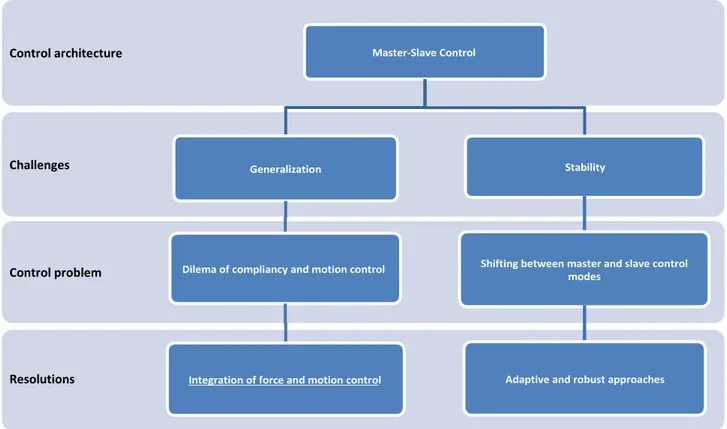
Figure 2-7 Represents the main challenges that impedance control has encountered. Control architecture
Challenges
Control problem
24
2.3.1.2 Integrated control approach
In such approach the controller is designed to simultaneously control force and position of the robot end-effector. The compliance of end-effector to the environment and trajectory tracking can be defined as the major subtasks of interaction control required to be achieved simultaneously. This fact reveals the necessity of the integration of both position and force control in such task. Raibert and Craig established the fundaments of hybrid force/motion control architecture by means of defining the concepts such as “natural and artificial constraints of force and position” (Raibert and Craig, 1981). Later on, a method was developed by Hayati (Hayati, 1986) to control a multi-manipulator cooperative task. The core idea of the proposed approach was based on: decomposition of the joints torques into two terms contributed to the position and force of end-effector and the mentioned twofold constraints were employed to shift between force and position control modes for each joint. It also takes advantages of two separate force and position feedbacks to calculate the relevant joint torques. In other words, the torque commands vector is divided in to two parts: first is calculated based on the position error and the other is calculated based on the force error (5).
( )
where and are position and force errors calculated based on desired and measured values of position and force at the end-effector. The and are functions used to calculate the torques of the joints contribute to the position and force calculated based on the position and force errors of the end-effector respectively. As regards the block diagram illustrated in Figure 2-8 and using equations of (Uchiyama and Dauchez, 1988), these functions are described as (7) and (8):
( ) ( )
The matrix interprets the orientation errors to the equivalent rotation vectors. The Jacobian matrix is employed to transform the joint velocity ̇ into the operational-space velocity . The matrix operators and represent the position and force control signals contributed to the relevant control laws. The gain matrices and are assumed to be diagonal; their diagonal elements convert velocity and force commands into actuator commands. The matrix is the selection matrix and is the identity matrix having the same dimensions as . The proposed constraints by Craig and Raibert (Raibert and Craig, 1981) are the references to design the selection matrix . The vectors of measured joint variables and measured end-effector generalized forces are denoted by and , respectively. Their transformation to the operational space, respectively, are denoted by and . The and are standing for the desired motion and force trajectory respectively.
Figure 2-8 A schematic diagram of hybrid control.
Based on the Raibert and Craig study (Raibert and Craig, 1981), the mentioned structured of the hybrid position/force control has not always a stable behavior due to problem in kinematic transformation (i.e., kinematic instability). The researchers showed that the stability of the system with the mentioned hybrid position/force control scheme depends on the type of the interaction with the environment and a proper choice of selection matrix (Li and Gruver, 1997). Another study also showed that the control scheme has a stable behavior in case of application to rigid constraints (Goldsmith et al., 1997). Detailed information of the trajectory and dynamics of the environment is required in order to define the virtual constraints: in presence of uncertainties the controller will encounter instability. In other words, it would work just in particular tasks; therefore, the task specification is one of its main limitations.
The controller instability occurs not only due to the environment uncertainties, but even in the specified environment due to the discrete nature of the controller. As the mechanical behavior of the environment changes during the interaction so, the instantaneous transition between force and position control modes endangers the stability of the system. Therefore using such architecture will make it impossible to carry out fundamental operations, such as self-regulation of small planning errors or recovery from unexpected impacts when large contact forces may arise. However, the proposed method by Chiaverini and Sciavicco (Chiaverini and Sciavicco, 1993) was able to successfully eliminate the above mentioned drawbacks by employing a priority-based solution, but the system performance was reduced when in contact with the environment.
A dilemma between having low stiffness to guarantee the compliance of the end-effector and high stiffness to achieve the aims in position control is considered as the other drawback of such discrete control algorithm. Since the interaction with the environment requires such a compliant system (Vukobratović and Stojić, 1995) it is compulsory for a robot involved in the interaction to have not only a variable but also an adjustable stiffness to be able to deal with the mentioned paradox.
26
Accordingly an adaptive control strategy was proposed to control force/position of the end-effector in interaction with the unknown-stiffness environment by employing of scaled position trajectory based on the stiffness of environment (Villani et al., 1999). A time-varying factor is exploited in case of unknown stiffness. Despite the merits of the algorithm, it can be employed only in case that the end-effector is in contact with the environment.
The PD force/motion control is considered as another adjustment on hybrid control architecture. It follows a Lyapunov-based approach to divide the force and PD-type position control laws (Wen and Kreutz-Delgado, 1992). Namely, the joint torques for each arm is computed as the combination of two contributions of position and internal forces/torques. The first portion is a PD-type term including a feedback/feed-forward model-based compensation term and the second one is based on the force feedback of the robot end-effector.
Generally, the overall structure of this control approach is the same as the previous scheme as it also divides the joints torques inputs into the two parts previously mentioned. The only differences are in the approaches that employed to calculate 1) the position control signal and 2) the joint torques (through using internal forces). A PD control law in task space together with gravity compensation is employed for trajectory control purpose (Caccavale et al., 2000).
̇
Where and are positive definite matrixes and represent the derivative and proportional coefficients respectively. also is a block diagonal matrix and is the gravity compensation term is defined based on (12). In equation (11) represents the task-space error calculated by using (10) where is vector of desired joint variables and is the vector of the gravitational forces/torques acting at the manipulators joints, is the vector of gravity forces/moments at the manipulated
object. is the grasp matrix and denotes a pseudo-inverse of (Caccavale et al., 2000). The internal force/torque term is calculated based on the Jacobian matrix , internal force/torque
and matrix which is the full-column-rank matrix spanning the null space of grasp matrix (Caccavale and Uchiyama, 2008). This term calculate as (13).
The internal force is designed by employing a linear filter to eliminate the steady state error as
(14).
( )
The desired and measured internal forces/torques are represented by and and also
is a linear filter, such that has zeros only in the left half plane (Caccavale and Uchiyama, 2008). The can be computed based on the measured forces/torques at end-effector as . Caccavale et al. (Caccavale et al., 1999a) employed a kineostatic filtering in order to eliminate the