Classe di Scienze Sperimentali
Settore di Ingegneria Industriale e dell’Informazione
Smart Charging Algorithm Optimization
Supervisors:
Prof.ssa Maria Chiara Carrozza
Ing. Federico Caleno
Ing. Eleonora Sammartino
Candidate:
Isabel Naranjo De Candido
Non c’è via d’uscita
Deh, è giunta l’ora ch’io debbo andare.
Ringrazio la mia tutor, Prof.ssa Maria Chiara Carrozza, per il sostegno e l’interessamento che ha sempre dimostrato nei miei confronti.
Ringrazio Eleonora Sammartino, per la pazienza che ha avuto nel seguirmi e darmi le indicazioni per questa tesi e per i bei mesi che ho trascorso presso Enel X.
Dal punto di vista degli affetti, inizio senza dubbio dal ringraziare mia madre e mio padre, per tutto ciò che significano per me.
Seguendo l’ordine cronologico, la terza persona che voglio ringraziare è la mia amica di una vita e chi ha convivissuto con me negli anni delle superiori, perché mi ha fatto crescere molto allora e continua tuttora ad essere importante.
E arriviamo al Sant’Anna. Senza la Scuola non sarei neanche lontanamente ciò che sono ora. Le esperienze che mi ha consentito di vivere sono incommensurabili, ma non avrebbero questo inestimabile valore astraendole dalle persone che le hanno rese possibili. Ricordo l’esperienza e la qualità del Corpo Docenti e l’Amministrazione e l’umanità, la disponibilità e la fondamentale e quotidiana importanza della Segreteria Didattica, la Mensa, la Portineria e le Pulizie.
Ci sono poi le persone con cui sono stata sulla stessa barca per questi sei anni. Persone interessanti, strane, a volte opportuniste, sempre disponibili, geniali, fuori dal mondo, fin troppo dentro alle cose del mondo, un po’ saccenti, modeste. Conoscenti, amici e non proprio. Quanti gli aneddoti divertenti, personali e a volte imbarazzanti che ricordo di questi anni! Bambinoni appena usciti dalle superiori che diventano adulti insieme, in un collegio che non permette la minima privacy e che ricorda e tramanda. In questo contesto non posso non menzionare Hammameth al mio primo anno e poi la progettazione degli armamenti per La Battaglia (e il suo arbitraggio...).
Voglio ringraziare coloro per i quali ho dovuto installare Telegram, per la compagnia, l’affetto, le uscite e le conversazioni mai banali ma spesso senza senso.
E devo un ringraziamento particolare a ciascuna delle amicizie nate in collegio, con cui ho condiviso passeggiate prima di cena, chiaccherate sul senso delle cose, lunghe riflessioni e sfoghi sui problemi della vita (mi sono sorbita tanti di quei problemi sentimentali...),
ragionamenti su questioni da risolvere e stratagemmi da mettere in atto, o semplicemente dei pranzi o delle cene a mensa, dei consigli e delle benevole prese in giro.
E per fortuna che non sono tutti santannini! C’è chi ho conosciuto grazie all’Università di Pisa, ai viaggi in Cina e in USA, alla tesi e chi fa parte di più di una di queste categorie o di nessuna. Grazie perché, nonostante le distanze, riusciamo a mantenere l’amicizia.
Alcune persone continueranno ad essermi a fianco nel futuro, altre rimarranno dei punti nella linea del tempo passato; vorrei ringraziare, dunque, anche tutte le persone che sono entrate e poi uscite dalla mia vita in questi anni di università.
Grazie a tutti, per le gioie e i divertimenti condivisi nei momenti più belli e per il sostegno nei momenti più difficili (ma soprattuto, nel momento più buio finora).
The e-mobility revolution poses a number of challenges to the current electric management system that have to be addressed and solved. One of them is the control of the charging processes, needed in order to reduce the impact of the EV recharges on the grid. The algo-rithm for smart charging currently in use at Enel X was tested and some criticalities were highlighted. Suggestions to overcome the mayor issues identified are then proposed.
Contents
Contents v
List of Figures vii
List of Tables viii
1 Introduction 1
2 Overview of the Electric Vehicles 2
2.1 State of the art . . . 2
2.2 Comparison with ICEs . . . 9
2.3 General structure of an EV . . . 10 3 Charging an EV 16 3.1 Regulatory framework . . . 16 3.2 Charging modes . . . 17 3.3 Connection cases . . . 19 3.4 Connection means . . . 21 3.4.1 AC charging . . . 22 3.4.2 DC charging . . . 24
3.5 Solutions for EV charging . . . 26
3.6 Communication between the EV and the charging station . . . 26
4 Managing the charging processes 31 4.1 Introduction . . . 31
4.2 About the need of and active control of the charging process . . . 34
4.3 Grid components and entities . . . 35
4.4 Communication among the stakeholders . . . 36
4.6 Enel X smart charging scenario . . . 40
5 Tests and suggestions 44 5.1 General improvements to the algorithm . . . 44
5.2 Vehicle A characterization . . . 49
5.3 Vehicle B characterization . . . 54
5.4 Smart charging tests with multiple vehicles . . . 59
6 Conclusions 64
References 65
List of Figures
2.1 EV architecture [14] . . . 12 2.2 BEV structure [16] . . . 14 3.1 Mode 1 . . . 17 3.2 Mode 2 . . . 18 3.3 Mode 3 . . . 19 3.4 Mode 4 . . . 19 3.5 Case A . . . 20 3.6 Case B . . . 20 3.7 Case C . . . 213.8 AC connection means (Type 1, Type 2, Type 3A, Type 3C) . . . 23
3.9 DC connection means (Combo 1, Combo 2, CHAdeMO, Tesla) . . . 24
3.10 Typical CP Circuit [6] . . . 27
3.11 Typical PWM sequence during a recharge [15] . . . 28
4.1 Local demand profile and electric car charging in the European Union on a typical day (Below 2 Degrees Scenario in 2030, 200 millions of EVs, 15% of the total) [5] . . . 33
4.2 Grid entities and communication system . . . 35
4.3 Uncontrolled charging example . . . 39
5.1 Example of a power and energy plot for vehicle A . . . 49
5.2 End of charge for vehicle A (x: time [minutes], y: power [kW]) . . . 52
5.3 Example of a power and energy plot for vehicle B . . . 55
5.4 End of charge for vehicle B (x: time [minutes], y: power [kW]) . . . 57
5.5 Simulation A (x: time, y: power absorbed) . . . 60
5.6 Simulation B (x: time, y: power absorbed) . . . 61
5.7 Simulation C (x: time, y: power absorbed) . . . 62
List of Tables
2.1 BEV models available in Europe as of 2018 [8] . . . 3
2.1 BEV models available in Europe as of 2018 [8] . . . 4
2.2 Charging power. . . 5
2.3 P-HEV functional classification . . . 6
2.4 S-HEV functional classification . . . 7
2.5 PHEVs models available in Europe as of 2018 [8] . . . 7
2.5 PHEVs models available in Europe as of 2018 [8] . . . 8
2.5 PHEVs models available in Europe as of 2018 [8] . . . 9
3.1 Enel charging station models . . . 25
5.1 Derating due to temperature. . . 46
5.2 “Finite power levels” procedure example . . . 48
5.3 “Finite power levels” procedure for vehicle A . . . 51
Chapter 1
Introduction
Enel X is working towards a future in which electric mobility (e-mobility) represents a viable solution for the reduction of greenhouse gases linked to transportation and for the modernization of the electric grid.
In Chapter 2, after an overview of the Electric Vehicle (EV) state of the art and a compar-ison between them and Internal Combustion Engine vehicles (ICEs), the general structure of an EV will be described.
Chapter 3 will focus on the charging process of an EV: the regulatory framework, the charging modes, the connection cases and the connection means, differentiating between AC and DC charging. Then, Enel X solutions for EV charging will be described, as well as how communication between the EV and the charging station works.
The way the charging process is managed will be the main topic of Chapter 4. An introductive part will describe the issues, challenges and opportunities due to the integration of e-mobility in the current electric grid. The need of and active control of the charging process will be then highlighted. Grid components and entities and the communication among the stakeholders are essential to understand the charging control and to introduce Enel X smart charging scenario.
Finally, in Chapter 5 the current smart charging algorithm will be tested and suggestions for improving it will be introduced on the basis of these tests. First, general improvements to the algorithm will be suggested. Then, following the characterization of the two vehicles in use during the tests (Vehicle A and Vehicle B), specific tuning of the algorithm for each of the two vehicles will be proposed. Further, a smart charging tests with multiple vehicles will be described.
Chapter 2
Overview of the Electric Vehicles
An Electric Vehicle (EV) is a vehicle in which one or more electric motors provide propul-sion power. This can be the only power available for propulpropul-sion or it can be coupled to other propulsion systems. Both Purely Electric Vehicles (PEVs) and Hybrid Electric Vehi-cles (HEVs) belong to this category. [14] The vehiVehi-cles of interest for this thesis are Battery Electric Vehicles (BEVs), a subcategory of PEVs, and Plug-in Hybrid Electric Vehicles (PHEVs), as they are the two categories rechargeable from the electric grid. In particular, we will consider only four-wheeled commercial vehicles belonging to the categories L6e, L7e, M1 and N1.
2.1 State of the art
EVs can be divided in two main categories: PEVs and HEVs.
PEV
A PEV is a vehicle in which one or more electric motors provide propulsion power and this is the only power available for propulsion. PEVs can be divided into BEVs and Fuel Cells Electric Vehicles (FCEVs). [14] In the latter, the Hydrogen stored in the vehicle tank reacts in a controlled way with the Oxygen contained in air producing water and electricity. This is not a technology of interest for this thesis, so it will not be further analyzed.
BEV
There are a number of different technologies and sizes for the energy storage systems; the most used for vehicles are batteries, in some special cases in conjunction with super
capaci-tors because of their high power-energy ratio. Between the battery typologies nowadays the most used are Lithium batteries. [14]
BEV available in Europe The EV market is growing day by day. The brands and models of BEVs currently available on the European market are listed in Table 2.1 [8], that in-cludes also the main technical features of interest for this thesis. For the sake of clarity, the information about the Charging Power (CP) is further analyzed in Table 2.2.
The current supplied to the vehicle can be a one phase alternating current (AC 1 PH), a three phases alternating current (AC 3 PH) or a direct current (DC).
Table 2.1: BEV models available in Europe as of 2018 [8]
Brand Model Connector Current Max CP Battery Range BMW i3 Combo 2 AC 1 PH 7.4 kW
33 kWh 245 km AC 3 PH 11 kW
DC 50 kW Citroen C-Zero Type 1 AC 1 PH 3.7 kW
16 kWh 150 km CHAdeMO DC 50 kW
E-Mehari Type 1 AC 1 PH 3.7 kW 30 kWh 200 km Berlingo Type 1 AC 1 PH 3.7 kW
22.5 kWh 170 km Van Full E CHAdeMO DC 40 kW
Ford Focus E Type 1 AC 1 PH 7.4 kW 23 kWh 160 km Hyundai Ioniq E Combo 2 AC 1 PH 7.4 kW
28 kWh 250 km DC 100 kW
KONA E Combo 2 AC 1 PH 7.4 kW
64 kWh 482 km DC 70 kW
Jaguar I-PACE Combo 2 AC 1 PH 7.4 kW
90 kWh 480 km DC 100 kW
Kia Soul EV Type 1 AC 1 PH 7.4 kW
27 kWh 210 km CHAdeMO DC 100 kW Mercedes B ED Type 2 AC 1 PH 3.7 kW 28 kWh 200 km AC 3 PH 11 kW Vito Type 2 AC 1 PH 3.7 kW 36 kWh 130 km E-CELL AC 3 PH 11 kW
Mitsubishi i-MiEV Type 1 AC 1 PH 3.7 kW
16 kWh 150 km CHAdeMO DC 50 kW
Table 2.1: BEV models available in Europe as of 2018 [8]
Brand Model Connector Current Max CP Battery Range Nissan e-NV200 Type 1 AC 1 PH 7.4 kW
24 kWh 170 km CHAdeMO DC 50 kW
LEAF Type 2 AC 1 PH 7.4 kW
40 kWh 378 km CHAdeMO DC 50 kW
Opel Ampera-e Combo 2 AC 1 PH 7.4 kW
60 kWh 520 km DC 50 kW
Peugeot iOn Type 1 AC 1 PH 3.7 kW
16 kWh 150 km CHAdeMO DC 50 kW
Partner E Type 1 AC 1 PH 3.7 kW
22.5 kWh 170 km CHAdeMO DC 40 kW
Renault Fluence E Type 1 AC 1 PH 3.7 kW 22 kWh 185 km Kangoo E Type 2 AC 1 PH 7.4 kW 33 kWh 270 km Twizy Type 3A AC 1 PH 2.3 kW 6.1 kWh 100 km Zoe Q90 Type 2 AC 1 PH 7.4 kW 41 kWh 370 km AC 3 PH 22 kW AC 3 PH 44 kW Smart Fortwo ED Type 2 AC 1 PH 7.4 kW
17.6 kWh 145 km AC 3 PH 22 kW
Tesla Model S Type 2 AC 1 PH 7.4 kW
100 kWh 613 km AC 3 PH 22 kW CHAdeMO DC 50 kW Tesla SC DC 120 kW Model X Type 2 AC 1 PH 5.5 kW 100 kWh 542 km AC 3 PH 16.5 kW CHAdeMO DC 50 kW Tesla SC DC 120 kW VW E-Golf Combo 2 AC 1 PH 3.7 kW 35.8 kWh 300 km AC 2 PH 7.4 kW DC 50 kW e-Up! Combo 2 AC 1 PH 3.7 kW 18.7 kWh 160 km DC 40 kW
Voltage Current Current type Charging power Connector type
230 V 10 A AC 1 PH 2.3 kW Schuko, Type 1, Type 2 230 V 16 A AC 1 PH 3.7 kW Schuko, Type 1, Type 2 230 V 24 A AC 1 PH 5.5 kW Type 1, Type 2 230 V 32 A AC 1 PH 7.4 kW Type 1, Type 2 400 V 16 A AC 2 PH 7.4 kW Type 2 400 V 16 A AC 3 PH 11 kW Type 2 400 V 24 A AC 3 PH 16.5 kW Type 2 400 V 32 A AC 3 PH 22 kW Type 2 400 V 63 A AC 3 PH 43.5 kW Type 2 400 V 125 A DC 50 kW CHAdeMO 500 V 125 A DC 62.5 kW CHAdeMO 400 V/500 V 200 A DC 100 kW Combo 2 480 V 300 A DC 120 kW Tesla connector
Table 2.2: Charging power.
HEV
An HEV is an EV in which the propulsion power originates from more than one independent sources, of which at least one has to be from a storage battery and the second one is generally an Internal Combustion Engine (ICE).
HEV classification
HEVs can be divided primarily based on their physical architecture. [14] The main cate-gories are the following:
• Parallel HEV (P-HEV): all the power is converted to mechanical power before the summation. Essentially, the power supplied by the battery is converted to mechanical power and then summed to the power provided by the ICE. Its structure is more similar to the one of an ICE than to the one of a BEV. In fact, it performs better in highways, whereas it is less efficient in the urban traffic.
• Series HEV (S-HEV): all the power is converted to electric power before the summa-tion. Essentially, the power supplied by the ICE is converted to electrical power and then summed to the power provided by the battery. Then an electrical motor supplies torque to the wheels. Its structure is more similar to the one of a BEV than to the one
of an ICE. In fact, it performs better in the urban traffic, whereas it is less efficient in highways.
• Series-Parallel HEV (SP-HEV): it combines the features of a P-HEV and a S-HEV. At lower speeds it operates more as a S-HEV while in highways, where the series drivetrain is less efficient, the ICE takes over.
• Axle-Split HEV (AS-HEV): the power provided by the two sources is summed di-rectly on the road. In fact, one axle is powered by the ICE and one by the electric system.
• Power-Split-Device HEV (PSD-HEV): the power is summed in a more complex way. The Power Split Device (PSD) is a gears system that combines part of the two powers. Additionally, they all can be plug-in or not.
In table 2.3 and 2.4 P-HEV and S-HEV respectively are subdivided based on a functional classification. [14]
Functional classification
Start/Stop Mild HEV Strong HEV PHEV Function Start/Stop X X X X Regeneration X X X X Electric assistance X X X Electric driving X X Plug-in charging X NEDC savings 4-5% 10-15% 20-30% 50-70% Hybridization grade ————————————>
Functional classification Range Extender Full HEV Function Start/Stop X X Regeneration X X Electric assistance X X Electric driving X X Plug-in charging (*) (*) Full full-power range X Hybridization grade ——————>
Table 2.4: S-HEV functional classification PHEV
A PHEV is an HEV that can be connected to the grid to recharge its battery. It derives all or part of its energy from an on-board rechargeable energy storage system. It is an EV that can charge the rechargeable electrical energy storage device from an external electric source and also derives part of its energy from another on-board source. [14]
PHEV available in Europe While HEV have more operation history, PHEV diffusion is more recent. In table 2.5 the PHEV models present on the European market as of today are listed. [8]
Table 2.5: PHEVs models available in Europe as of 2018 [8]
Brand Model Connector Current Max CP Battery E range Audi A3 e-tron Type 2 AC 1 PH 3.7 kW 8.8 kWh 50 km
Q7 e-tron Type 2 AC 1 PH 3.7 kW 17.3 kWh 56 km AC 3 PH 7.4 kW BMW 225xe PHEV Type 2 AC 1 PH 3.7 kW 7.6 kWh 41 km 330e PHEV Type 2 AC 1 PH 3.7 kW 7.6 kWh 40 km 740e PHEV Type 2 AC 1 PH 3.7 kW 9.2 kWh 48 km i8 Type 2 AC 1 PH 3.7 kW 7.1 kWh 35 km
Table 2.5: PHEVs models available in Europe as of 2018 [8]
Brand Model Connector Current Max CP Battery E range X5
xDRIVE 40e
Type 2 AC 1 PH 3.7 kW 9 kWh 31 km Chevrolet Volt Type 1 AC 1 PH 3.7 kW 16 kWh 60 km Fisker Karma Type 1 AC 1 PH 3.7 kW 20 kWh 80 km Ford C-MAX Energi PHEV Type 1 AC 1 PH 3.7 kW 7.6 kWh 44 km Hyundai IONIQ PHEV Type 2 AC 1 PH 3.7 kW 8.9 kWh 50 km KIA Niro PHEV Type 2 AC 1 PH 3.7 kW 8.9 kWh 58 km
Optima PHEV Type 2 AC 1 PH 3.7 kW 8.9 kWh 54 km Mercedes C350 Type 2 AC 1 PH 3.7 kW 6.2 kWh 31 km GLC 350e PHEV Type 2 AC 1 PH 3.7 kW 8.7 kWh 34 km MINI Cooper S E Country-man ALL4 Type 2 AC 1 PH 3.7 kW 7.6 kWh 40 km Mitsubishi Outlander PHEV Type 1 AC 1 PH 3.7 kW 12 kWh 60 km Opel Ampera Type 1 AC 1 PH 3.7 kW 16 kWh 60 km Porsche Cayenne S E-Hybrid Type 2 AC 1 PH 7.4 kW 10.8 kWh 36 km Panamera S E-Hybrid Type 2 AC 1 PH 3.7 kW 9.4 kWh 36 km Range Rover Sport PHEV Type 2 AC 1 PH 7.4 kW 13.1 kWh 51 km Toyota Prius PHEV Type 2 AC 1 PH 3.7 kW 8.8 kWh 50 km VW Golf GTE Type 2 AC 1 PH 3.7 kW 8.7 kWh 50 km
Table 2.5: PHEVs models available in Europe as of 2018 [8]
Brand Model Connector Current Max CP Battery E range Passat GTE Type 2 AC 1 PH 3.7 kW 9.9 kWh 50 km Volvo S90 T8 PHEV Type 2 AC 1 PH 3.7 kW 9.2 kWh 50 km V60 PHEV Type 2 AC 1 PH 3.7 kW 11.2 kWh 50 km V90 T8 PHEV Type 2 AC 1 PH 3.7 kW 9.2 kWh 50 km XC60 T8 PHEV Type 2 AC 1 PH 3.7 kW 10.4 kWh 56 km XC90 T8 Twin Engine PHEV Type 2 AC 1 PH 3.7 kW 9.2 kWh 43 km
2.2 Comparison with ICEs
At the very beginning of the history of vehicles (mid-19th century) both EVs and ICEs were present in the early market, and in the very first times EVs were more in use than ICEs. The main reasons for the prevalence of EVs were the fact that EV were faster, had a larger autonomy, reliability, immediate and easy start up, no noise and no smelly emissions. Then the ICE technology had mayor improvements whereas EVs did not evolve likewise, leading to an overtake of the firsts. The main reasons were the better performances of the new ICEs, the lower cost of ICEs due to the new chain production introduced by Ford, the simplification of the start up phase and the lower cost of oil. In particular, there was not such an improvement in batteries that could balance the new long ranges and low refueling time of the new ICEs.
Nowadays, the new environmental and health concerns have raised the issue of pollution caused by ICEs. The improvements of electronics and of batteries technology from the ’90s paved the way to a new generation of EVs, that increasingly show more advantages than disadvantages. There is a continuos ongoing work addressed to the elimination of the disadvantages of EVs. [12]
A list of pros and cons of EVs is reported below.
Pros
• partial energy recovery while braking and going downhill. In ICE vehicles power cannot go up from the wheels-brakes system as the ICE is unable to absorb it (apart from the small part that causes the so-called engine brake)
• high reliability of the components part of the EVs, most of which are steady state elec-tric parts, in comparison with the major number of mechanical moving components in ICEs
• high tank to wheel efficiency (67% to 81%) and even well to wheel (around 30%) compared to ICEs (both values around 15%)
• no noise
• no smelly and dirty emissions
• more distributed charging possibilities: people can charge their own vehicles even at home
Cons
• lower range compared to ICEs
• longer charging times with respect to the refueling time of ICEs • need of an electric grid adaptation to sustain the new loads • need of a new type of infrastructures for the charging • high batteries prices
• higher vehicles prices
2.3 General structure of an EV
An EV has a considerable lower number of components and of moving parts with respect to an ICE. The main innovations with respect to ICEs are described below.
Electric motor
An EV has at least one electric motor. The more advanced models of PEVs tend to have at least two electric motors, one for each driving wheel. In general, the sizes of the motors vary between 50 kW for the smallest city cars and the 150 kW for the high performance ones, with a higher peak of 300 kW for the supercars and lower peak of 4kW-15 kW for the motorized quadricycles.
They can be brushless motors, also called permanent magnets synchronous motors, or induction motors, also called asynchronous motors. The stator of this two motors is es-sentially the same, the rotor constitutes the real difference. The synchronous motor has a permanent magnet rotor while the asynchronous one has a shorted structure inside. Peak point efficiency is generally higher in a synchronous motor because less heat is produced. It can operate at unity power factor, whereas the best for the asynchronous drive is about 0.85. In the asynchronous motors, at light loads the inverter can reduce the voltage such that magnetic and conduction losses are reduced. Thus, with a smart inverter, it has an advantage over a synchronous machine and this becomes increasingly important as perfor-mance is increased. With synchronous motors, as machine size grows, the magnetic losses increase proportionately, while with asynchronous motors, as machine size grows, losses do not necessarily grow. Permanent magnets are expensive and permanent magnet rotors are difficult to handle when anything ferromagnetic gets close to them. Spinning asynchronous machines produce little or no voltage when de-excited so they are easier to protect. On the other hand, asynchronous machines are more difficult to control. In conclusion, syn-chronous drives will likely continue to dominate in the HEVs and asynsyn-chronous drives will likely maintain dominance for the high-performance PEVs. [9]
Transmission
A transmission is needed in an ICE because it needs to operate at a relative high number of revolutions per minute (rpm), generally between 1000 and 5000 rpm. The torque transmitted is increased decreasing the number of revolutions with a gearbox. A differential is also needed to allow the wheels to rotate at a different speed.
In general, in a BEV (and also a S-HEV) this is not needed and a fixed gearing can be enough. Only some kinds of sport EVs include a gearbox, always with a maximum of two/three different ratios. In facts, the electric motors operate well at all speeds.
In fig. 2.1 the architecture in relationship with the transmission scheme is illustrated. [14]
it has been completely abandoned.
The schemes b) and c) represent the second evolution, but as they include a differential they are progressively being abandoned.
The last stage of simplification leads to the schemes d) e) and f), which show one motor per driving wheel, eliminating the need for a differential because of the individual torque control. This are the schemes currently envisaged for the future vehicles.
The scheme of a P-HEV is similar to schemes a) and b). Generally speaking, the ICE and the electric motor are coupled by a PSD, a planetary gearbox. This represents by itself a continuously variable transmission, so there is no need for an additional gearbox. However, there is obviously the need for a differential.
Figure 2.1: EV architecture [14]
Battery
The energy storage system can be a monolithic battery system, with more cells of the same type, or a hybrid system, with a part dedicated to power management (for acceleration
and braking) and one dedicated to energy storage (to guarantee a good range). The power management can be achieved with electrostatic systems, as super capacitors, whereas the energy storage is obtained by the use of batteries. Generally speaking, BEVS and HEVS require energy oriented and power oriented batteries, respectively.
The most common type of batteries as today are Lithium batteries. [12] At least five main Lithium-based chemistries exist and the most developed and spread is the Li-ions technology.
The typical architecture of a battery includes several cells, that connected in series in the same case are called modules, which together constitute the strings and the battery pack. Each cell is capable of generating only a few volts, so they are set in series to reach a power of the order of kWs. In some rare cases the strings can be connected in parallel to raise the current output of the battery. [14]
Inside of each cell, with different modalities depending on their typology, a flow of charge occurs due to chemical transformations between the electrodes and the electrolytic solution.
The general characteristics of a battery are:
• nominal capacity (C): charge that can be extracted from a fully charged battery in a given time T
• nominal current (A): current linked to the nominal capacity: C=I*T
• nominal voltage (V): voltage of each cell multiplied by the number of cells in series • max/min voltage (V): maximum and minimum voltages at which the battery can
op-erate
• specific energy (Wh/kg): maximum energy stored divided by the battery weight • energy density (Wh/L): maximum energy stored divided by the battery volume • specific power (W/kg): maximum power divided by the battery weight
• power density (W/L): maximum power divided by the battery volume
• self discharge: speed at which the battery suffers from a progressive reduction of extractable energy
• useful life: the battery shows an initial increase in capacity and then suffers from a progressive loss of it. Calendar life is related to the aging over time (years) and cycle life is related to aging over cycles of charge and discharge
In any case, the higher the discharge current the lower the extractable energy. The ex-tractable energy depends also on the temperature and the humidity.
To preserve as far as possible the capabilities of a Li-ions battery the recommended charging profile is a constant current/constant tension profile. During the first part of the charging process, the current delivered is the maximum current supported by the battery, as it is the fastest way to charge it. As soon as the voltage approaches the maximum voltage, the current is diminished maintaining the voltage constant at the maximum voltage available, thus switching to a constant voltage control till the end of the charging process. [13]
Figure 2.2: BEV structure [16]
Battery charger
The battery charger converts the 1 PH or 3 PH alternating current to a direct current. The rectification can be performed with simple uncontrolled diode rectifiers or with more com-plex AC/DC converters that show a cleaner absorbed current wave. Then a Power Factor Corrector (PFC) increases the power factor and in a third stage a DC/DC converter lowers the voltage on the battery side. The weight of the rectifier increases with the maximum power it can handle, and that is one of the reason why DC current is used at high charging powers. In the latter case, the rectifier is placed inside the EVSE and the voltage is limited by the maximum battery voltage (400-800 V), which is generally higher than the AC volt-age. [15] It is important to mention that, by regulation, the EV power factor must be 0.9 during all the charging process except for the beginning and the end of it. [1]
Battery Management System
The Battery Management System (BMS) records the most important parameters for the safe operation of the battery, such as voltage, current, State Of Charge (SOC), internal temperature of the battery and ambient temperature. Then it provides inputs to the protection devices to generate alarms or disconnect the battery in case of emergency. Its main functions are the following:
• control and monitoring the charging and discharging of the battery, managing also the communication with the charging station
• ensuring the safe operation and protecting the battery from any damage
• monitoring and management of the state of health and state of life of the battery It also supervises the cell charge balancing, also called cells equalization. Since the current is the same for all the cells connected in series, theoretically the SOC should always be the same for all the cells. On the other hand, non-homogeneity in self-discharge and other minor phenomena cause the unbalance of the SOC of the different cells. As the charging process of the battery is stopped whenever the most charged cell is full and the discharging ends whenever the less charged cell is empty, equalization is strictly needed to reach an extractable charge as close as possible to the nominal capacity.
A passive balancing is made with resistors that discharge the most charged cells to equal-ize their charge with the others. It has a low capital cost but it involves energy losses. The more the cells are similar the more this solution is convenient. If the unbalancing speed is slow, the cost of energy lost in resistors is negligible and the lower cost of passive equaliza-tion prevails. In an active balancing process the most charged cells supply energy to the less charged ones. It can be cost effective to compensate for cheap, uneven cells. [15]
Chapter 3
Charging an EV
There are a number of aspects involved in the charging of an EV. This Chapter will mainly focus on the components closer to the user: the EV, the cable with the connectors and the charging station. On Chapter 4 the other elements important for the charging process will be analyzed.
3.1 Regulatory framework
A number of regulations apply to the EV charging process: • IEC 61851 “Electric vehicle conductive charging system”
• IEC 62196 “Plugs, socket-outlets, vehicle couplers and vehicle inlets - Conductive charging of electric vehicles”
• ISO/IEC 15118 “Road vehicles - Vehicle to grid communication interface”
• ISO/IEC 17409 “Electrically propelled road vehicles - Connection to an external elec-tric power supply - Safety requirements”
• IEC 63110 “Protocol for Management of Electric Vehicles charging and discharging infrastructures”
• IEC 61000-3-2 “Limits - Limits for harmonic current emissions (equipment input current 16 A per phase)”
• IEC 61000-3-12 “Limits - Limits for harmonic currents produced by equipment con-nected to public low-voltage systems with input current >16 A and 75 A per phase”
3.2 Charging modes
The methods for connecting the EV to the grid in order to supply energy to the vehicle itself are called charging modes. In [6] the four different allowed charging modes are described. Briefly, Mode 1 is a slow charging process from a domestic electrical socket (1 PH or 3 PH AC), Mode 2 is a slow charging process from a domestic socket but with some EV specific protection arrangement and an in-cable protection device (1 PH or 3 PH AC), Mode 3 is a slow or fast charging process using a specific EV multi-pin socket with control and protection functions (1 PH or 3 PH AC) and Mode 4 is a fast charging process using an off board charger with some special charger technology (DC).
A more precise definition of the different charging modes and functions for energy trans-fer to EVs, taken from [6], is reported below.
Mode 1
Mode 1 is a method for the connection of an EV to a domestic standard socket-outlet of an AC supply network, utilizing a cable and plug not fitted with any supplementary pilot or auxiliary contacts. The rated values for current and voltage shall not exceed:
• 16 A and 250 V AC 1 PH • 16 A and 480 V AC 3 PH
EV supply equipment intended for Mode 1 charging shall provide a protective earthing con-ductor from the domestic standard plug to the vehicle connector. In Italy, Mode 1 charging is prohibited in public areas by the national regulation and is permitted only in private areas not accessible to third parties. Further, the maximum current allowed is 10 A.
Mode 2
Mode 2 is a method for the connection of an EV to a standard socket-outlet of an AC supply network utilizing an AC EV supply equipment with a cable and plug, with a control pilot function and system for personal protection against electric shock placed between the standard plug and the EV. The rated values for current and voltage shall not exceed:
• 32 A and 250 V AC 1 PH • 32 A and 480 V AC 3 PH
Current limitations are also subject to the standard socket-outlet ratings. EV supply equip-ment intended for Mode 2 charging shall provide a protective earthing conductor from the standard plug to the vehicle connector. Mode 2 equipment that is destined to be mounted on a wall but is detachable by the user, or to be used in a shock resistant enclosure shall use protection equipment as required by IEC 62752. In Italy, Mode 2 charging is prohibited in public areas by the national regulation and is permitted only in private areas not accessible to third parties. The use of IEC 60309-2 accessories is recommended for Mode 2 connections for more than 10 A.
Figure 3.2: Mode 2
Mode 3
Mode 3 is a method for the connection of an EV to an AC EV supply equipment permanently connected to an AC supply network, with a control pilot function that extends from the AC EV supply equipment to the EV. EV supply equipment intended for Mode 3 charging shall provide a protective earthing conductor to the EV socket-outlet and/or to the vehicle connector.
Figure 3.3: Mode 3
Mode 4
Mode 4 is a method for the connection of an EV to an AC or DC supply network utilizing a DC EV supply equipment, with a control pilot function that extends from the DC EV supply equipment to the EV. Mode 4 equipment may be either permanently connected or connected by a cable and plug to the supply network. EV supply equipment intended for Mode 4 charging shall provide a protective earthing conductor or protective conductor to the vehicle connector.
Figure 3.4: Mode 4
3.3 Connection cases
The cable assembly consists of a flexible cable or cord fitted with a plug and/or a vehicle connector, used to establish the connection between the EV and the supply network or an EV supply equipment. A cable assembly may include one or more cables, with or without a fixed jacket, which can be in a flexible tube, conduit or wire way. A cable assembly can be detachable or be a part of the EV or the EV charging station as described below. [6]
Case A
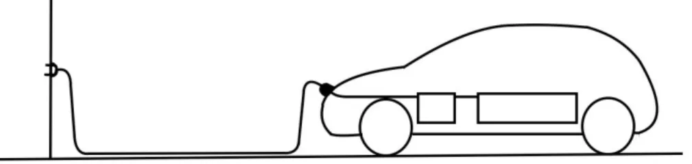
Connection of an EV to the supply network with a plug and cable permanently attached to the EV. This case is generally associated to Mode 1 or Mode 2.
Figure 3.5: Case A
Case B
Connection of an EV to a supply network with a cable assembly detachable at both ends.
Figure 3.6: Case B
Case C
Connection of an EV to a supply network utilizing a cable and vehicle connector perma-nently attached to the EV supply equipment. This case is compulsory for Mode 3 in case of a current supply >32 A and for Mode 4.
Figure 3.7: Case C
3.4 Connection means
Four different terms must be defined:
• EVSE socket-outlet: a specific socket-outlet intended to be used as part of an EV supply equipment and defined in the IEC 62196 series. In general, a socket-outlet is an accessory having socket-contacts designed to engage with the contacts of an EV plug and having terminals for the connection of cables or cords. In the case that the cable is detached from the charging station (Case A or B), the EV socket-outlet is the part of the charging station that fits with the cable from the charging station side. • Plug: a specific plug intended to be used as part of an EV supply equipment and
defined in the IEC 62196 series. In general, a plug is an accessory having contacts designed to engage with the contacts of an EV socket-outlet, also incorporating means for the electrical connection and mechanical retention of flexible cables or cords. In the case that the cable is detached from the charging station (Case A or B), the EV plug is the first part of the cable from the charging station side.
• Connector: an accessory having contacts designed to engage with the contacts of an EV inlet, also incorporating means for the electrical connection and mechanical retention of flexible cables or cords. In the case that the cable is detached from the vehicle (Case B or C), the EV connector is the first part of the cable from the EV side. • EV inlet: an accessory having socket-contacts designed to engage with the contacts of an EV connector and having terminals for the connection of cables or cords. In the case that the cable is detached from the vehicle (Case B or C), the EV inlet is the part of the EV that fits with the cable from the EV side.
The standard plugs and socket-outlet are plugs and socket-outlet which meets the require-ments of any IEC and/or any national standard that provides interchangeability by standard sheets.
Vehicle adaptors shall not be used to connect a EV connector to a EV inlet. Adaptors between the EV socket-outlet and the EV plug shall be used only if specifically designated and approved by the vehicle manufacturer or by the EV supply equipment manufacturer and in accordance with national requirements. Such adaptors shall not allow transitions from one mode to another. Not even cable assemblies shall allow transitions from one mode to another. [6]
In the following paragraphs the different types of connections in use as of today are described. [3]
3.4.1 AC charging
The following contacts may be present in an AC connector: [6] • up to three phases (L1, L2, L3)
• neutral (N)
• protective conductor (PE)
• control pilot (CP): it verifies the continuity of the PE during the charging process and ensures the bidirectional communication between the EV and the charging station • proximity contact (PP): it notifies to the EV the presence of the mobile connector and
identifies the size of the cable
Schuko
EEC 7/4 type F. The Schuko connector is the connector standard used in Europe, present in all appliances that can require more than 10 A, with an intensity limit of 16 A. It is especially common in scooters and electric bikes.
Type 1
A Type 1 plug is a 1 PH vehicle coupler reflecting the SAE J1772/2009 automotive plug specifications, as defined in IEC 62196-2. It has 2 pilot contacts (CP and PP) and the inter-lock and retention systems are compulsory. The protection degree against electric shocks is
Figure 3.8: AC connection means (Type 1, Type 2, Type 3A, Type 3C)
IPXXB. It is designed for a voltage till 250 V and a current till 32 A. It exists only as an EV inlet on the EV and as an EV connector on the cable on the vehicle side.
Type 2
A Type 2 plug is a 1 PH or 3 PH vehicle coupler reflecting the VDE-AR-E 2623-2-2 auto-motive plug specifications, as defined in IEC 62196-2. It has 2 pilot contacts (CP and PP) and the interlock and the retention systems are compulsory. The protection degree against electric shocks is IPXXD. It is designed for a voltage till 500 V and a current till 63 A. To limit lack of interoperability issues, the European Commission has stated that all electric vehicles must have installed the “Type 2” connector.
Type 3
A Type 3 plug is a 1 PH or 3 PH vehicle coupler with shutters reflecting the EV Plug Alliance proposal, as defined in IEC 62196-2.
Type 3a
It has 1 pilot contact (CP) and the interlock and the retention systems are optional. The protection degree against electric shocks is IPXXD. It is designed for a voltage till 250 V and a current till 16 A (1 PH). It is designed for light vehicles.
Type 3c
It has 2 pilot contacts (CP and PP) and the interlock and the retention systems are optional. The protection degree against electric shocks is IPXXD. It is designed for a voltage till 500 V and a current till 63 A (1 PH/3 PH). It exists only as an EV socket-outlet on the charging station and as an EV plug on the cable on the charging station side.
Figure 3.9: DC connection means (Combo 1, Combo 2, CHAdeMO, Tesla)
3.4.2 DC charging
CHAdeMO
The CHAdeMO connector was designed by TEPCO "Tokyo Electric Power Company". It is a connector suitable for Mode 4 charging which currently provides up to 200 kW using DC. Communications with the vehicle is addressed through CAN bus.
CCS Connectors (COMBO)
The CCS connectors incorporates a pair of terminals for DC recharges in an AC socket-outlet and plug.
Combo Type 1
The SAE J1772 combo connector incorporates an extra pair of terminals for DC recharges and hence allows its use for Mode 4 recharges. Its supported voltage is up to 500 V, with currents from 80 to 200 A (40-100 kW).
Combo Type 2 CCS
The Combo Type 2 connector is a variant of the previously described Mennekes, and incor-porates a new connector with a pair of terminals for DC recharges so that it use in charging Mode 4 up to 500 V and 200 A is allowed (100 kW).
Tesla
Tesla’s own plug is the smallest DC connector and supports up to 120 kW. For its super-charger in Europe, Tesla uses a modified version of the Type 2 connector (without CCS).
Type Voltage Current Type Po wer Connector type A C Juice Box for pri vate 3 kW 230 V 16 A A C 1 PH 3.7 kW One rechar ge at a time with a Type 2 or Type 3a sock et-outlet 22 kW 400 V 32 A A C 3 PH 22 kW One Type 2 sock et-outlet A C Juice Pole for cities 22 kW 230 V 32 A A C 1 PH 7.4 kW Tw o sock et-outlets: Type 2 and/or Type 3a 400 V 32 A A C 3 PH 22 kW A C Juice Pole for cities 43 kW 400 V 64 A A C 3 PH 43 kW One Type 2 connector Multistandard Fast Char ge Quartetto 400 V 32 A A C 3 PH 22 kW One Type 2 sock et-outlet 400 V 64 A A C 3 PH 43 kW One Type 2 connector 50 V to 500 V 120 A DC 50 kW One rechar ge at a time with a CHAdeMO or Combo 2 connector Trio 22 kW 400 V 32 A A C 3 PH 22 kW One Type 2 sock et-outlet 50 V to 500 V 120 A DC 50 kW One rechar ge at a time with a CHAdeMO or Combo 2 connector Trio 43 kW 400 V 64 A A C 3 PH 43 kW One Type 2 connector 50 V to 500 V 120 A DC 50 kW One rechar ge at a time with a CHAdeMO or Combo 2 connector V2G V2G DC 10 kW Bidirectional, CHAdeMO only Table 3.1: Enel char ging station models
3.5 Solutions for EV charging
A number of producers and a number of different models of charging stations exist. The models commercialized by Enel that are in use as of today are summarized in Table 3.1.
The Wallbox/Box Station is thought for slow charging for private use, the Pole Station for public charging, the Fast Charge Station and the Fast Recharge Plus for public fast charging and the V2G Station for a bidirectional transit of current. They are all designed to be user friendly, as the presence of an operator in proximity of each charging station is not envisaged. [10]
3.6 Communication between the EV and the charging
sta-tion
Installed on board of the EV, the BMS is responsible for the communication with the EV supply equipment. It has to translate the signals coming from the EVSE into instructions for the charging process. Inside each EV supply equipment, two systems manage the infor-mation and the communication:
• CP: it is a control system that manages the EVSE electronics and allows the moni-toring and diagnostic of the EVSE components. It also manages the communication between the charging station and the EV.
• CM: it manages the information interchange between the EVSE and the remote con-trol center. All the CP operations are memorized and sent to the concon-trol center. The way in which the EV and the EVSE communicate is based mainly on analog signals and secondarily on digital signals. [15]
PWM
The analog communication is performed sending a series of standard signals, called control pilot function, over the Control Pilot Circuit (CPC), used in Mode 2, Mode 3 and Mode 4. It is the charging station that sends a Pulse-Width Modulation (PWM) signal to the vehicle to communicate the current that can be absorbed by the vehicle. The vehicle can just communicate if it is ready or not for the charging process by opening and closing a switch located on the EV side of the control circuit. Two types of control pilot function are possible, simplified and typical, corresponding respectively to the simplified and typical control pilot circuit. An EV using the simplified control pilot circuit shall limit itself to
single phase charging and shall not draw a current of more than 10 A, so in the following part of this paragraph only the typical CPC (Figure 3.10) will be taken into account.
Figure 3.10: Typical CP Circuit [6]
A typical sequence of signals during a charging process is shown in Figure 3.11. The EV supply equipment communicates by setting the duty cycle of a PWM signal or a continuous DC voltage signal. The EV responds by applying a resistive load to the positive half-wave to the control pilot circuit. The basic PWM signal generated by the EVSE has a value of +-12 V and a frequency of 1 kHz. Before the EV connection the voltage measured by the EVSE is +12 V (state A). When the vehicle is connected the voltage becomes +9 V (state B1) and then the voltage is made to oscillate between +9 V and -12 V (state B2). When the vehicle is ready for the charging process, it closes a switch and the voltages starts to oscillate between +6 V and -12 V (state C). The charge begins. Varying the duty-cycle of the PWM signal (the width of the +6 V signal), the information about the current that can be absorbed as well as some other service information are transmitted to the vehicle. After the time needed the charge ends, the vehicle opens its switch and the signal oscillates again between +9 V and -12 V (state B2). The connector on the EVSE is opened and the cable can be unplugged. [6]
The minimum of current signal that can be sent is 6 A, while the maximum is 80 A. The analog signal is then converted to a digital signal by the battery charger.
The EVSE CP selects the current value to send as the minimum of the followings: • maximum current supported by the cable checking the resistor coding
• maximum current supplied by the control remote center
• maximum current allowed by the temperature inside the CU to avoid the switching of the protection devices
• maximum current due to the configuration in the control remote center • nominal current of the socket-outlet
This fact has to be taken into account especially in the case of a smart charging process, because that could mean that the desired current may not be available in some cases.
Figure 3.11: Typical PWM sequence during a recharge [15]
Mandatory functions in Modes 2, 3, and 4
The following control pilot functions shall be provided by the EV supply equipment: • Continuous continuity checking of the protective conductor
• Verification that the EV is properly connected to the EV supply equipment • Energization of the power supply to the EV
• De-energization of the power supply to the EV • Maximum allowable current
Compliance is checked by inspection and test where applicable. If the EV supply equip-ment can supply more than one vehicle simultaneously, it shall ensure that the control pilot function performs the above functions independently at each connecting point. The control pilot functions can be achieved using a PWM signal and a control pilot or by any other non PWM system that provides the same results. EV supply equipment designed for Mode 2 or Mode 3, using the control pilot conductor and utilizing accessories according to IEC 62196-2, shall be provided with a control pilot function. [6]
Digital communication
The drawback of the DC charging solution is that the communication real time requirements on the EV-EVSE interface increases as the rectifier on the EVSE and the BMS on the EV must be able to communicate via this interface. The prevention of an incorrect charging state requires a real time communication, which is tailored to the charging process. The digital communication standard in use as of today are the following:
• IEC 61851-1 Annex D • IEC 61851-24
• ISO 17987 • ISO/IEC 15118 • DIN SPEC 70121
• Daimler Protocol (Smart)
The following paragraphs will briefly describe the digital communication standard in use as of today.
IEC 61851-1 Annex D
This Annex D specifies a control pilot function that provides bidirectional communication between LIN nodes in the charging station and in the EV. Optionally, a third LIN node may be present in a cable assembly. LIN-CP is based on the same control pilot circuit that is used for PWM-CP. This makes it easy to design backward compatible charging stations and EVs that implement both PWM-CP and LIN-CP.
IEC 61851-24
IEC 61851-24:2014, together with IEC 61851-23, applies to digital communication between a d.c. EV charging station and an electric road vehicle (EV) for control of d.c. charging, with an a.c. or d.c. input voltage up to 1 000 V a.c. and up to 1 500 V d.c. for the conductive charging procedure. The EV charging mode is mode 4, according to IEC 61851-23. Annexes A, B, and C give descriptions of digital communications for control of d.c. charging specific to d.c. EV charging systems A, B and C as defined in Part 23.
ISO 17987
ISO 17987 (all parts) specifies the use cases, the communication protocol and the physi-cal layer requirements of an in-vehicle communication network physi-called Lophysi-cal Interconnect Network (LIN).
ISO/IEC 15118
Digital communication as described in ISO/IEC 15118 series may be carried out over the control pilot conductor. Additional components can be needed to couple this high-frequency signal onto the control pilot signal.
AC/DC charging. DIN SPEC 70121
The digital communication between an EV and an EVSE defined in DIN SPEC 70121 is based on an early unpublished version of the ISO/IEC 15118 series of documents. As the ISO/IEC 15118 series has since undergone further development, there are now technical differences between DIN SPEC 70121 and the ISO/IEC 15118 series.
DC only. Combo2 connector. Mainly used in Germany: BMW, Volkswagen, etc. Daimler Protocol (Smart)
Chapter 4
Managing the charging processes
At a first glance, reading Chapter 3 it seems that there are no external entities that influence the charging process, and the only players involved are the EV and the EVSE. In this Chap-ter, the reasons why there is the need not only of an energy provider, but also of a number of components that will work together in order to manage the charging processes will be illustrated.
4.1 Introduction
In the past decades, the loads acting on the grid were, for the major part, predictable, and the energy provider was unique for each State. There were big consumers and small consumers with defined energy consumption trends and essentially only medium and big power plants connected to the grid and controlled by the same energy agent. This was convenient for the grid, as the generation and distribution could be controlled without major difficulties, in an era in with electronics and informatics were not developed as today.
Then, more recently, the introduction of small local generators, for the most part un-predictable renewable energy plants, and the liberalization of the market, lead to increasing difficulties in the energy management. The renewable energy generation is variable depend-ing on day by day conditions, mostly unpredictable in terms of instant power and no flexible in terms of power modulation. The electric grid is envisaging major modifications to handle the not easy task of balancing in real time energy supply and demand. Adding an extra source of unpredictability, as EV charging could be, may be deleterious for the grid. In this moment, the low number of EVs does not pose serious threats, but in the future they could become an issue.
Actually, EVs could be an advantage for the grid. If the actual concept of mobility does not chance too much, it has been seen that most of the private vehicles are active in the
morning and in the afternoon, as they are mainly used to travel from home to work. Even in the case of small EVs that means that, for each car connected to the grid, there is an availability of at least 20 kWh with a charging power of a minimum of 3.7 kW, but more commonly 7.4 kW for at least eight hours during the day and eight hours during the night. This could help to manage the unbalance between energy demand and energy production during the central hours of the day, that are the most critical. In the first part of the afternoon there is the peak of production by solar panels, but at the same time the energy demand is not at its maximum, that is around 5 p.m.. During the night there is a big drop of the power demand, that could be increased with the help of the EVs charging. The goal is to flatten as much as possible the demand of production from the big power plants, as the power installed needed is linked to the maximum power required, not only to the average power delivered. In addition, EVs could not only absorb energy when the production is higher than the demand, but also deliver current to the grid when the demand is higher. For this reasons, the future grid must be a smart grid: bidirectional, flexible and digital. This target is strictly linked to the ability to control, both in time and in power, the EV charging process. In Figure 4.1 a possible scenario for Europe in 2030 is shown. [5]
Actual situation
Nowadays, commonly the EV Charging Process is uncontrolled. That means that an EV, after the connection to the charging station and the payment authentication (if needed), starts charging at the maximum power available. There is not an active control of the charging process.
Growth perspectives
In 2017, for the first time, the global sales of new EVs passed the one million units threshold. Under the current trends, by 2020 this achievement could be almost quadruplicated, moving to 4.5 millions units, that will be around 5% of the global light-vehicle market, reaching 20% or 25% by 2030. BEV sales are growing faster that PHEV sales. In absolute terms, China’s EV sales is bigger than the European and American one put together, even if the adoption rate represents only 2% on a national level. Europe’s EV market grew by almost 40% from 2016 to 2017 and Norway’s EV sales-penetration rate reached 32% in 2017. [5] EV market
Global automakers will launch approximately 340 BEV and PHEV models before 2020. The new models are always more far away from the initial niches, as high-performance
Figure 4.1: Local demand profile and electric car charging in the European Union on a typical day (Below 2 Degrees Scenario in 2030, 200 millions of EVs, 15% of the total) [5] sports car and mid-range small city cars, moving also to midsize and volume-segment vehi-cles. The benchmark models have surpassed the 300 km target, that make this cars poten-tially attractive for the majority of the customers.
Several countries are setting end dates for the sale of ICEs. For example, Norway will make BEVs the 100% of new sales by 2025 while California, France and UK will stop ICEs sales by 2040.
The fact that in the next years the trends for mobility could abruptly change must be taken into account. The majority of the statistics are made on today’s car divers, but it is every day more clear that young people are always less prone to own a car, preferring public transportation, car-sharing and e-hailing instead.
Government incentives could also make the difference, as Norway and China cases show. [5]
Infrastructures
The availability of EVSE is one of the key factors for the market penetration of EVs. As the number of EV sold has continued to increase, private and public charging infrastructure have also grown. In 2016, the annual growth rate of publicly available charging was 72%, hence of a similar magnitude of the EV stock growth rate in the same year (60%). Global EVSE outlets passed 2 millions in 2016, with more that 200,000 public slow chargers (3.7 kW < x < 22 kW) and 100,000 public fast chargers. Public EVSE growth is primarily driven by the rapid increase in the number of fast chargers, as the charging time (coupled with a low range) is the perceived limit for EVs strong diffusion. However, analyzing the Norway case as the most significative one because of the strong penetration of the EVs, this fears seems unmotivated. In fact, it can be seen that EV charging does not match refueling habits for ICEs, as EV owners most frequently charge their vehicles at home and secondly at work, relying on slow chargers. Then they use less frequently public slow chargers, chargers located in commercial facilities and the last used are fast charging stations, as they primarily supply planned stops for long-distance trips. Trends studies show that 80% of users travel no more than 50 km per day, a range well compatible with EVs use.
For comparison, as of today there are 2,700 public charging points in Italy, 25,500 in Germany, 16,300 in France, 14,300 in UK, 10,300 in Norway and 5,000 in Spain. On the other hand, in Italy there are 23,000 oil distributors, 14,700 in Germany, 12,500 in France, 9.000 in UK and 9,000 in Spain.
EVSE deployment is supported by the development of standards ensuring interoperabil-ity, by financial incentives, regulations and permits. [5]
4.2 About the need of and active control of the charging
process
The rapid growth of the market will lead to a big number of EVs circulating in the nearest future. Each car means a quite important load on the grid with respect to an average house, and an EV fleet may lead to mayor problems for the grid, if the charging processes were performed at the same time of the peaks of energy demand. This is the main reason to state that the EV charging processes must be regulated. Looking at it with a positive approach, a number of EVs could help managing and flattening the power curve, making them to recharge during the slots with a low request of energy. In the future, with a V2G approach, they could help the grid providing energy during the high demand peaks. In addition, in some particular cases, users could decide to use their EV battery to deliver electric energy
to their house.
How charging processes are expected to be managed in the future
In the near future a closer integration between the grid entities is expected. This will pri-marily lead to a close communication between the entities that will regulate the charging processes.
4.3 Grid components and entities
The grid entities that have or will have a role in the charging process managing in the scenario described in [7] are introduced below. The EV and the EVSE are omitted as already described in Chapter 2 and 3.
Figure 4.2: Grid entities and communication system
Charging Station Operator
The Charging Station Operator (CSO) operates the EVSE and is responsible for some or all functions of installation, maintenance, and operation of EVSEs for public service. It manages the charging process of each EVSE and forwards the charging session information to each Charge Service Provider.
Charge Service Provider
The Charge Service Provider (CSP) manages and authenticates EV user credentials and may provides charging and Value Added Services (VAS) for the users. If EV drivers are
allowed to use a single credential and contract to access services on multiple e-Mobility networks, information exchanges and related provisions between CSPs are needed; this service is called roaming. For roaming services, two CSPs are involved. The visited CSP collects meter data and charging session information from the visited CSO, then creates a Charge Detail Record (CDR) and forwards it to the home CSP directly or through the Clearing House.
Clearing House
The Clearing House (CH) is an optional intermediate actor that facilitates authorization, billing and settling procedure for roaming EV charging services between two different CSPs. It can provide centralized service efficiency in the case there are many CSPs. It should be a different and separate entity from all CSPs.
Energy Vendor
The entity that sells the electric energy to the CSP.
Energy producers
The entities that supply electric energy to the grid. They can be renewable or non-renewable energy generators.
Transmission System Operator
The Transmission System Operator (TSO) is the player that manages the transmission of the electric energy through the grid, typically in High Voltage (HV), and the balancing between energy offer and demand. It is also responsible for the primary, secondary regulation.
Distribution System Operator
The Distribution System Operator (DSO) is the player that manages the last section that connects the grid to the final users, typically in Medium and Low Voltage (MV, LV).
4.4 Communication among the stakeholders
All stakeholders have different communication needs and protocols that have to match when communicating between each other. The scenario described is taken from [7].
User-EVSE
Example credentials include RFID card, credit card or user/password inputs from station displays.
User-CSP
It can take place through a mobile application, a web page or similar. Supported credentials include NFC-based RFID, static or dynamic QR code, and username + password.
EV-CSP
Embedded credential supported by automated ID recognition, as for example a digital cer-tificate for plug and charge defined in ISO/IEC 15118 series.
EV-Third Party
The functions may include remote control and management of the EV.
EV-EVSE
Mainly aimed at power supply and charging session management. It may also include smart communication functions specified in ISO/IEC 15118 series.
EVSE-CSO
This interface may include credential authentication, EVSE charging status exchange, and charging session management.
CSO-CSP
It may be an internal interface within one entity or an external interface between two entities.
CSP-CH
It specifies EV roaming process through centralized CH mode. The roaming functions may include credential authentication, EVSE charging status exchange, charging session remote control and management and charging transaction billing and settlement. IEC 63119-1.
CSP-CSP
It specifies EV roaming process through peer-to-peer direct mode. The visited CSP may also be a CSO. IEC 63119-1.
CSP-DSO
To implement smart grid functions, the DSO could send to the CSPs power set point pro-files to be followed, that are translated into power curves to be followed by each EVSE connected.
CSP-Third Party
Third-party services may include intelligent transportation service, navigation service, park-ing lot service, public transportation card service and many others.
4.5 Charging control
As said, charging control will be essential when EV penetration will be stronger.
Uncontrolled charging
It is the simplest way to manage a charging process. The EV absorbs energy at the maximum power available till a SOC depending on the EV battery characteristics, generally around 85% or 90%. Then the power absorbed decreases till the end of the charging process, as in Figure 4.3. The maximum power available is determined locally as linked to the current constrains. [16] In particular, it is selected as the minimum of the followings:
• maximum current supported by the cable checking the resistor coding • maximum current supplied by the control remote center
• maximum current allowed by the temperature inside the CU to avoid the switching of the protection devices
• maximum current due to the configuration in the control remote center • nominal current of the socket-outlet
Figure 4.3: Uncontrolled charging example
Smart charging
In a future with a strong penetration of EVs one of the goals will be not to burden the grid with the charging processes. CSPs will have a convenience or will be forced to control the power delivered to each EVSE time by time. The factors that must be taken into account in a smart charging process are the following:
• timing the EV will stay connected to the EVSE • final SOC desired by the EV user
• grid power requirements and needs
• EV limiting factors linked to charging power and energy storage • EVSE constrains
The information exchange will follow a path similar to the one described below: • The user successfully authenticates with his/her home CSP
• The user plugs in the car
• The user selects the maximum charging time • The user selects the final SOC desired
• The information is transmitted to the CSP
• The CSP elaborates a possible load curve compatible with the grid constrains and user preferences
• If needed, the CSP modifies the load curves of other ongoing smart charging processes • If expected, the CSP takes into consideration also future smart charging reservations
parameters
• The CSP translates the power information into a current signal
• The CSP transmits each current load curve to the corresponding EVSE
• The EVSE transmits to the EV, for example, via a PWM signal the current set point time by time
• The EV adapts the charging process to the value received
There are various tests ongoing to verify the functioning of this process. As of today, all the automatic information flux between the grid and the CSP is only simulated, and the power set points are manually introduced in the system.
Probably, fast charging on motorways will not be subject to smart charging, as this kind of charging process is thought to deliver the maximum power to the EV to charge it as quickly as possible.
V2G
An ulterior step for smart charging will be the bidirectionality of the current flux to and from the vehicles. This will help not only to absorb energy when there is less demand, but also to cut the peaks providing energy to the grid when more needed. The information path will be similar to the one already described for smart charging, but the possible bidirectionality will make the calculations more complex and will probably intensify the information flux. The V2G concept could also work in case of isolated homes or as a strategy to buy energy at a lower price and to use it later when it is sold at a higher price.
4.6 Enel X smart charging scenario
As of today, the structure described in Sections 4.3 and 4.4 is not completely in place. Enel X manages all its EVSE using the Enel Electric Mobility Management (EMM) platform,
a multi tenant system that acts CSO and CSP roles. All the recharges are managed as uncontrolled charging, while smart charging and V2G are being tested in a number of R&D stations. The driver for smart charging can be an external system as Charge Advisor (CA).
Charge Advisor
The algorithm is deeply under R&D. The user logs in using a mobile app and registers his contract and his vehicle(s). To start a recharge it is necessary to open the app and set the following parameters:
• EVSE and socket-outlet where to recharge • Time of start of the recharge
• Desired duration of the recharge • EV to recharge
• Initial SOC (in %, as shown on the vehicle monitor) • Desired final SOC (typically 100%)
The information about the EV to recharge allows the system to understand the battery size and how the power curve will look like during the charging process, as will be explained in Chapter 5. Then the user taps on the start button. The CA central system receives a smart charging request notification and asks EMM to unlock the socket-outlet on the selected EVSE. Then the user plugs in the cable and the recharge starts.
Essentially, the function of CA is to make the vehicle(s) to follow a load curve during the charging process. The load curve is a simulation of the possible power curve that the DSO could ask CA to follow. With more than one vehicle charging at the same time, the target curve is the sum of the power values that the vehicles have to follow minute by minute. In this case, CA has to distribute the power between the vehicles respecting the parameters set by the user. [11]
CA sends to EMM a list of power values to be set minute by minute during the following minutes, and each minute it receives back from EMM the following data referred to the last minute:
• maximum power • energy delivered
• PWM sent to the EV (in case of an AC charging) • current on each one of the three phases
• voltage on each one of the three phases
Example of information exchanged during a smart charging session
As CA is perceived by EMM as an external caller that asks for a recharge on a EVSE con-trolled by EMM, the communication between them is regulated by the Enel InterCharge Protocol (EICP). EICP is one of the communication interface that EMM offers to any ex-ternal caller to allow it to perform a recharge on a charging point managed by EMM and to receive the data recorded by EMM [4]. In particular, each minute during the recharge EMM sends a Charging Session Scheduling Request, and each five minutes CA sends back the new power curve.
The chain that links the power value sent by CA to the information read by the EV is the following:
• CA sends the power value to EMM
• EMM receives it and transforms it into a current value using the formula: A =380·0.998·P p 3
• The current value is then transformed into a PWM value: PW M = b A 0.6c
• The PWM is then sent to the EVSE
• The EVSE reads the PWM and sends it as an analog signal to the EV
• The BMS of the EV reads the PWM and transforms it into a digital signal to control the charging process
Business model
Today’s situation is different from the one described in Sections 4.3 and 4.4. With the docu-ment Piano Nazionale Infrastrutture di Ricarica Elettrica – PNIRE, the Italian Governdocu-ment defines the guidelines to guarantee the unitary development of the charging services of EVs in Italy [2]. The major statements are the followings:
• At least two charging stations must be available per each EV for a complete recharge as well as a number of public charging stations for a possible complementary recharge to avoid range anxiety to users
• Each person must have granted the possibility to open and manage a public charging point and the cooperation of any DSO with no discrimination
• The price of electricity debited by all public charging stations must be fair; prohibitive extra charges cannot be applied to external users
• The creation of a charging network is urgent and a priority
An important aspect to be considered is the interoperability. It is the key for the success of electric mobility, as the user is free to recharge in any available station, independently on his own CSP or the EVSE CSO.
![Table 2.1: BEV models available in Europe as of 2018 [8]](https://thumb-eu.123doks.com/thumbv2/123dokorg/2926344.18626/12.892.131.795.477.1111/table-bev-models-available-europe.webp)
![Table 2.1: BEV models available in Europe as of 2018 [8]](https://thumb-eu.123doks.com/thumbv2/123dokorg/2926344.18626/13.892.127.794.209.1062/table-bev-models-available-europe.webp)


![Table 2.5: PHEVs models available in Europe as of 2018 [8]](https://thumb-eu.123doks.com/thumbv2/123dokorg/2926344.18626/17.892.128.795.230.1104/table-phevs-models-available-in-europe-of.webp)
![Table 2.5: PHEVs models available in Europe as of 2018 [8]](https://thumb-eu.123doks.com/thumbv2/123dokorg/2926344.18626/18.892.132.792.231.573/table-phevs-models-available-in-europe-of.webp)
![Figure 2.1: EV architecture [14]](https://thumb-eu.123doks.com/thumbv2/123dokorg/2926344.18626/21.892.226.685.433.915/figure-ev-architecture.webp)
![Figure 2.2: BEV structure [16]](https://thumb-eu.123doks.com/thumbv2/123dokorg/2926344.18626/23.892.164.755.386.659/figure-bev-structure.webp)