Università di Pisa
School of Graduate Studies “G. Galilei”
PhD Thesis in Chemical Sciences
Monomer and polymer indole-derived systems having NLO
properties for very high optical gain photorefractive materials.
The role of the electrostatic interactions.
Francesco Greco
Supervisor:
Referee:
Prof. Arturo Colligiani Prof. Vincenzo Schettino
Local Supervisor:
Prof. Giacomo Ruggeri
Contents
General object of the research
1
1
Introduction
3
1.1 The Photorefractive (PR) effect 4 1.2 Non Linear Optics (NLO) principles 11 1.3 Connections between molecular and “in bulk” NLO properties 17 1.4 Orientational contribution to photorefractive effect 20
1.5 Photoconductivity (PC) 26
1.6 Different categories of organic photorefractive materials 32 1.6.1 Guest-host photorefractive materials 33 1.6.2 Totally functionalized polymers 38 1.6.3 Low molecular weight organic glass formers (LMWG) 39
1.6.4 Liquid Crystals 41
1.7 Optoelectronic applications 42
1.8 The role of Tg and the importance of intermolecular interactions in PR organic
materials 45
1.8.1 Thermodynamics of miscible binary polymer blends 47
2
Indole-based
PR
materials
55
2.1 Why the indole group in polymers for PR materials 55
2.2 Aim of the research 60
3
Materials
and
Methods
63
3.1 Reagents and solvents 63
3.2 Methods and instrumentation for characterization 65
3.3 Syntheses 66
3.3.1 Synthesis of 3-[2-(4-nitrophenyl)ethenyl]-2-methylindole (NPEMI) 66 3.3.2 Synthesis of 3-[2-(4-nitrophenyl)ethenyl]-1-allyl-2-methylindole (NPEMI-A) 67
3.3.3 Synthesis of 3-[2-(4-nitrophenyl)ethenyl]-1-(2-ethylhexyl)-2-methylindole
(NPEMI-E) 69
3.3.4 Second NPEMI-E synthetic route 70
Synthesis of 1-(2-ethylhexyl)-2-methylindole 3-carboxaldehyde (ALD-E) Synthesis of 3-[2-(4-nitrophenyl)ethenyl]-1-(2-ethylhexyl)-2-methylindole (NPEMI-E) from ALD-E 3.3.5 Synthesis of 1-(2-ethylhexyl)-5-methoxyindole 3-carboxaldehyde (MeO-ALD-E) 73
3.3.6 Synthesis of 3-[2-(4-nitrophenyl)ethenyl]-1-(2-ethylhexyl)-5-methoxyindole (MeO-NPEI-E) 75
3.3.7 Synthesis of 1-(2-ethylhexyl)-5-nitroindole 3-carboxaldehyde (NO2-ALD-E) 77
3.3.8 Synthesis of 3-[2-(4-nitrophenyl)ethenyl]-1-(2-ethylhexyl)-5-nitroindole (NO2-NPEI-E) 78
3.3.9 Synthesis of 2,3-dimethyl-N-vinylindole (DMVI) 80
3.3.10 Synthesis of poly-(2,3-dimethyl-N-vinylindole) PVDMI 81
3.4 Preparation of photorefractive blends 81
3.5 Preparation of electrooptic cells for photorefractive measurements 85
3.6 AsymmetricTwo-Beam Coupling (2BC) meaurements apparatus 87
3.7 Measurement methods in the 2BC experiment 97
3.8 Photoconductivity measurements 101
3.9 Calorimetric analysis (DSC) 102
3.10 Spectroscopic Ellipsometry measurements 103
4
Results
and
Discussion
107
4.1 MOPAC-7 calculations of the relevant electrooptic parameters of the chromophores 107
4.2 Charge transfer complexes with TNFM. UV-Vis spectra 111
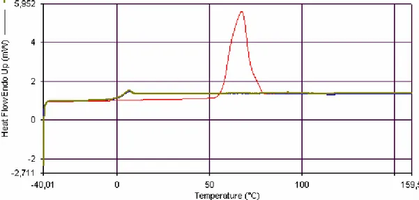
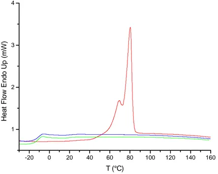
4.3 Calorimetric analysis (DSC) 118
4.3.1 Thermal behaviour of the NLO chromophores 119
4.3.1.1 NPEMI 121
4.3.1.2 NPEMI-A 123
4.3.1.3 NPEMI-E 124
4.3.1.5 NO2-NPEI-E 127
4.3.2 Thermal behaviour of binary polymer blends 129 4.3.2.1 PVDMI/NPEMI-E blends (NPE) 131 4.3.2.2 PVDMI/NPEMI-A blends (NPA) 137 4.4. Photoconductivity measurements 143
4.4.1 PVDMI/NPEMI-E blends (NPE) 144
4.4.2 PVDMI/NPEMI-A blends (NPA) 150
4.5 Photorefractivity measurements 155
4.5.1 PVDMI/NPEMI-E blends (NPE) 157
4.5.2 PVDMI/NPEMI-A blends (NPA) 162
4.6 Spectroscopic Ellipsometry measurements 166
5
Concluding
remarks 169
5.1 Conclusions 169
5.2 Expected developments 172
6
Experimental
spectra
175
6.1 1H and 13C Nuclear Magnetic Resonance spectroscopy 175
6.2 Infrared spectroscopy 180
6.3 UltraViolet and Visible spectroscopy 183
7
Glossary
187
7.1 Chemicals 187
7.2 Acronyms and abbreviations 188
Acknowledgments
189
References
191
General object of the research
Object of the present research is the study of some indole-based photorefractive (PR) materials. Novel indole-based NLO chromophores have been synthesized and their photoconductive (PC) and PR behaviour have been investigated when employed both alone (as low molecular weight glass forming multifunctional PR moieties) as well as in blends with a PC indolyl polymer, namely poly-(N-vinyl-2,3-dimethylindole). The aim was to get more insight in the onset of PR effect and to evaluate various contributions to it related to intermolecular interactions occurring among the components of a PR material. The introduction of increasing contents of polymer counterpart in PR blends containing the novel NLO chromophores permitted to follow these interactions in their onset and the establishment of new supramolecular arrangements, expected to be responsible for dramatic changes of electrooptic properties. In this way, it has been also possible to look for the proper formulation in order to take advantage of such interactions for the achievement of the best PC and PR performances. The joint analysis of the results of PC, PR and thermal (DSC) behaviour of the investigated materials revealed itself as particularly useful, due to the complexity of the many processes occurring simultaneously in organic PR materials. A careful comparison with numerous theoretical treatments permitted to rationalize the obtained results and to put in evidence the prominent role played by intermolecular interactions. On the other hand, the obtaining of long-term phase stability of amorphous PR materials, desirable for their practical use in a number of applications, was also a challenge. Many PR materials described in the past, indeed, although having good photorefractive properties, showed the undesirable drawback of fast recrystallization of one or more of their molecular components, leading to opacization of films and to the rapid loss of PR properties. Such aspect has been faced during this research obtaining indefinitely stable materials. As concerns PR, very large values of the photorefractive optical gain Γ (a main PR figure of merit) have been achieved in many cases, classifying the materials object of this research among the most efficient PR materials.
1
Introduction
The photorefractive (PR) effect refers to spatial modulation of the index of refraction under non-uniform illumination via space-charge-field formation and electrooptic nonlinearity1,2. The effect arises when charge carriers, photogenerated by a spatially modulated light intensity in a photoconductive material, separate by drift and/or diffusion processes and become trapped to produce a non-uniform space-charge distribution. The resulting internal space-charge electric field then modulates the refractive index to create a phase grating, or hologram, which can diffract a light beam. Because such an hologram can typically be erased by uniform optical illumination, PR holograms are dynamic, that is, they may be erased and rewritten many times. This last is one of many properties that distinguish PR materials from other mechanisms for hologram formation.
The PR effect has been observed and discovered for the first time in 1967 by a research group operating at Bell Telephone Laboratories3. They referred to it as a “detrimental effect” for the optics of nonlinear devices based upon LiNbO3 or LiTaO3 crystals. Prosecuting
that initial observation, many other research groups devoted themselves to the understanding of this effect. The challenge was twofold: on one side the need for a deeper and more comprehensive understanding of the principles and mechanisms ruling the effect and for a theoretical modelling; on the other side, or complementary to this, the work for the ideation and realization of new materials and devices, pushed also by new technological demands. During the years, since that first discovery, photorefractive effect has been observed in many other materials, the research in this field focussing mainly on inorganic crystalline materials, e.g. ferroelectrics (LiNbO3, BaTiO3, KNO3, SrxBa1-xNbO3), sillenites (Bi12SiO20),
semiconductors (InP, GaAs, CdTe, multiple-quantum-wells semiconductors)4. Inorganic crystalline materials, however, have several intrinsic drawbacks, concerning for example their processability, their expensiveness, their poor flexibility; all these reasons limited the spread of such materials in technological applications. One of the main problems is represented by the difficulties and cost relative to the growth of high purity grade crystals (a primary requirement for optical applications).
It was only at the beginning of ’90 that the discovery of the PR effect in organic crystals5,6, and then in amorphous and polymeric materials7,8, paved the way to the study of organic PR materials2. The main interest in this effect, besides the one aroused for the understanding of the complexity of phenomena related to it, lies in the potential use of
photorefractive materials as novel reversible recording media in many applications in the field of holography. Many of such applications has been proposed and realized, e.g. phase correlation, optical amplification, high density optical memory storage9,10,11,12,13.
1.1 The Photorefractive (PR) effect
As already briefly mentioned, the PR effect is based on the redistribution of electric charges (electrons or holes) photogenerated by a non-uniform pattern of light impinging on a material; this gives rise to a spatially variable internal electric field E which, mainly through the electrooptic effect (EO), modulates the refractive index of the medium. It deals effectively with the creation of an optical diffraction grating in materials possessing simultaneously electrooptic (non linear optics), photogeneration and photoconductivity properties.
The PR effect has been treated by Kukhtarev in his theory describing its mechanism in crystalline inorganic materials14. We use this theory in order to describe the effect; further specifications will be made in the following, including the successive modifications to the original theory, necessary to expand its application to molecular organic materials.
In the frame of Kukhtarev model, the PR material can be seen as a crystal containing only one typology of charge carrier (electrons e-), and two different typologies of so-called impurities, i.e. donors (D) and acceptors (A). D and A normally lie inside the forbidden band of the crystal, viz between valence band and conduction band. Optical excitations may permit the electrons to “hop” from non-ionized donors towards the conduction band, where they are free to move owing to diffusion (caused by charge density gradients) or drift (which is the case if an electric field is applied), until they recombine elsewhere with ionized donors.
Considering a crystal such as the one described so far, two laser beams are directed symmetrically on it, with incidence angles ±θ with respect to sample normal incidence; their propagation inside the material can be described by means of two plane electromagnetic travelling waves 1 1 1 10 j jk r E =E e eϕ − G G⋅ 2 2 2 20 j jk r E =E e eϕ − G G⋅ , (1.1)
being
E
1 beam 1 electric field,E
2 beam 2 electric field,E
10 andE
20 their respectiveamplitudes,
φ
1 andφ
2 their respective phases and kG1, kG2 being the wave vectors indicating the directions in which they are propagating.Figure 1.1 Schematic drawing displaying the process of writing of an hologram by means of the interference of two coherent laser beams of intensities I1 and I2. Interference pattern
(represented by dark and light planes) is formed, having periodicity Λg. K is the grating
wavevector (s. text).
These two intersecting coherent beams of light produce a standing-wave interference pattern, i.e. a time-independent but spatially modulated intensity pattern (interference pattern) described by the squared modulus of the electric field
(
)
2 2 2 1 2 10 20 2 10 20cos 2 1 I = E +E =E +E + E E K rG G⋅ +ϕ ϕ− (1.2) 2 1 k k KG = G − G . K JJGis called the grating wavevector.
Considering the system in a proper reference frame, s. Figure 1.1 and after some simple operations, it is possible to write down an analytical expression for the interference pattern in a more useful and immediately comprehensible way, i.e.
⎥ ⎥ ⎦ ⎤ ⎢ ⎢ ⎣ ⎡ ⎟ ⎟ ⎠ ⎞ ⎜ ⎜ ⎝ ⎛ Λ + = g x m I x I( ) 0 1 cos 2π (1.3)
in which I0 =I1 + I2 is the total incident intensity of light, m is called fringes visibility, Λg is the spatial wavelength or periodicity of the interference pattern. They are, respectively,
defined as →
K
Λ
gI
1I
2X
(
)
(
1 2)
2 1 2 1 2 I I I I m + = (1.4) θ λ sin 2 0 n g = Λ , (1.5)in which λ0 is the optical wavelength of the incident radiation in the vacuum, n is the index of refraction of the material, θ = θ2 – θ1 with θ1,2 the internal angles of incidence of the two
writing beams relative to the sample normal. For visible light (380 < λ0 < 750 nm) the spatial periodicity Λg can typically vary in the range from 0.1 up to 20-30 µm, depending on the angle between the beams. The grating wavevector KJJG lies along the normal direction with respect to the light and dark planes; its magnitude is given by K = 2π / Λg. In Figure 1.2 (a)
the optical intensity following a sinusoidal pattern is shown, being x the direction of the grating wavevector KJJG.
As we have previously mentioned, photoconductivity (PC) behaviour is a primary requirement for a material to show photorefractive effect. A PC material is an insulating one in the dark while it becomes a conductor under the exposure to light. Making an interference pattern, as the one described so far, to impinge upon a PC material gives rise to a spatially non-uniform excitation of couples electrons-ionized donors (holes), and, therefore, to the generation (photo-generation) of mobile charge carriers. Their density is proportional to the incident light intensity15; sites corresponding to the maxima of intensity of the interference pattern are the ones in which mobile electrical charge carriers photogeneration is maximum. The electrons (negative charge) or holes (positive charge) can therefore migrate from their original positions leaving behind fixed charges of opposite sign, through two different mechanisms: diffusion or drift. Diffusion is mainly related to charge density gradients inside
the material and play a minor role in photorefractive materials. When an external electric field is applied the main charge transport mechanism is due to drift, i.e. photogenerated electric
charges move under the effect of the electric field. The conductivity mechanism and the sign of the charge carrier (electrons or holes) depend on the nature of the material. It is important to remark here that charge mobility in a material is typically different for different kinds of charge carrier, i.e. one charge carrier is more mobile than the other one. If it would not be the case and both of them would possess the same value of mobility, the resulting charge distribution would be neutral, not giving rise to an internal electric field. For this reason, here and in the following of this study it has been referred only to one type of “charge carrier” (the
more mobile one), actually considering the other type as fixed. In organic amorphous materials charge migration is typically schematized by a hopping mechanism: the charge
carrier moves by “jumping” from one molecular site to the other. This kind of migration process is limited and regulated by the presence of the so-called traps, i.e. molecular sites in
which, by means of modified local potentials, charge carriers can live in a lower energy state. Indeed, traps are sites in which the mobile charges are blocked and excluded from the transport process for some time16. Traps in crystalline materials have been identified as ionic impurities, vacancies or defects in the crystal lattice. On the contrary, in organic amorphous photorefractive materials their nature has not yet been fully understood in detail, but it is surely related to the value of the ionization potential ip of the molecular species involved.
Figure 1.2 Schematic drawing summarizing the phenomena occurring in the formation of a PR grating. Space relationships between the incident light interference pattern, the resulting charge distribution, Space Charge Field Esc and the refractive index
modulation are displayed. The non-local nature of PR grating is reflected by the phase angle Θ.
Going back to the subject of the mechanisms involved in the illumination by an interference pattern of a PR material, the global effect is therefore represented by a migration
of free charges from “bright” regions towards “darker” regions, where charge mobility (and hence, conductivity) is lower and charges can be trapped. The distances typically covered in such migration process are in the order of few micrometers. This migration will result in a non-uniform charge density distribution ρ(x), s. Figure 1.2 (c), that will give rise in turn to an
internal electric field sinusoidally varying in space and called the Space Charge Field ESC (x), Figure 1.2 (d).
The equation that relates the charge distribution ρ(x) with the gradient of ESC (x) is known as the Poisson equation
ε πρ( ) 4 ) ( x dx x dEsc = , (1.6)
being ε the static dielectric constant of the material. Because of Poisson equation ESC has maxima in correspondence of ρ(x) = 0, that is between positive and negative charges centers,
thus resulting in a phase shift Θ = π/2 (displacement) between the internal field ESC and the charge distribution.
Kukhtarev14 in his theoretical treatment of the PR effect in crystalline inorganic materials gave an extremely accurate derivation of the space charge field. In the frame of this model, the amplitude of the electric field created by a sinusoidal interference pattern is given by the following expression
1 2 2 2 0 2 2 0 exp( ) 1 sc sc D sc D q q E E j E E E m E E E E = Θ ⎛ ⎞ ⎜ ⎟ ⎜ + ⎟ = ⎜ ⎟ ⎛ ⎞ ⎛ ⎞ ⎜ ⎟ + + ⎜ ⎟ ⎜ ⎟ ⎜⎜ ⎟ ⎜ ⎟ ⎟ ⎜⎝ ⎠ ⎝ ⎠ ⎟ ⎝ ⎠ (1.7)
in which E0 is the component of the applied static electric field along the pattern wave vector
K
JJG
, while ED, known as the diffusion field, is defined as
B D Kk T E e = . (1.8)
K = 2π / Λg is the wave vector of the interference pattern, kB the Boltzmann constant, T the temperature, e the elementary charge, and Eq is the so-called trap limited field that is defined
as 0 T q eN E Kεε = ; (1.9)
ε is the static dielectric constant, ε0 the static dielectric permittivity in the vacuum and NT
represents the numeral density of traps. Spatial phase shift Θ between the electric field ESC and the incident light intensity pattern in the same Kukhtarev’s description results to be
2 0 0 arctg D 1 D q D q E E E E E E E ⎡ ⎛ ⎞⎤ Θ = ⎢ ⎜⎜ + + ⎟⎟⎥ ⎢ ⎝ ⎠⎥ ⎣ ⎦ . (1.10)
If transport occurs only via diffusion, this phase shift is equal to π/2. Otherwise, Θ value depends on the relative forces of drift and diffusion processes. It is important to remark that, as a peculiar feature, PR effect produces only non-local gratings, that is gratings in which Θ ≠ 0.
The space charge field ESC , Eq. (1.7), gives rise to the modulation ∆n(x) of the local
refractive index inside the material, through the Pockels Effect or other non-linear optics
(NLO) related effects
( )
1 32 eff SC
n x n r E
∆ = − (1.11)
where n is the refractive index of the material and reff is the effective electrooptic parameter; it is actually a combination of different elements of the electrooptic tensor and it depends on the symmetry and mutual orientations of the NLO molecular moieties inside the material. The elements of the electrooptic tensor are related to the components of the second-order non linear susceptibility, of (2)
(
- ; 0,)
IJK
χ ω ω type, i.e. those relative to interactions of an optical field (ω pulsation) with a static dc electric field (pulsation ω=0)17,18. The sinusoidally varying refractive index modulation described by the Eq. (1.11) is actually a lattice; under the usual Bragg’s conditions this lattice is able to diffract light along certain, defined directions.
The phase shift Θ between I(x) and ∆n(x), Figure 1.2, gives rise to an asymmetric energy transfer (Asymmetric Two-Beam Coupling or 2BC), an effect that is peculiarly ascribed to the PR effect: one of the two incident beams (beam 2: “signal beam”) gains energy at the expense of the other beam (beam 1: “pump beam”). Coupling of these two beams can occur because both of them fulfill Bragg’s conditions for the lattice created by themselves. It could be said that the beams are “self-diffracted” by the lattice they have generated through their interaction with the PR material.
Such a mechanism applies to all holographic recording phenomena, including those producing local gratings (Θ = 0) like, for instance, those related to effects as photochromism or photoisomerizations, or those related to thermal, chemical, electronic nonlinearities2,19. In
all these effects transmitted light of one beam is dephased by π/2 in respect to other beam’s diffracted light. After the transmission through the material, both waves (I1,trans and I2,diffr,
I2,trans and I1,diffr, respectively) interfere each other identically in both directions. This is not the case for non-local gratings (Θ ≠ 0), like those produced by photorefractive effect: phase relationships existing between transmitted and diffracted parts are such that interference is constructive for one beam (signal beam increases) and destructive for the other beam (pump beam decreases). Phase shift is therefore a specific feature for photorefractive effect8,20,21. This feature is responsible for the energy transfer between the two beams. A strict treatment about the propagation of electromagnetic radiation at optical frequencies in a photorefractive material leads to the following equation9
(
)
0exp sin cos
2
E =E ⎡⎢Γ Θ + j Θ x⎤⎥
⎣ ⎦ . (1.12) Eq. (1.12) relates E, amplitude of the electric field associated with a beam at the exit from the
material, to E0, the value of the electric field of the same beam prior to the entrance. It actually describes the effect exerted on amplitude (and hence, on energy) by the photorefractive material. In Eq. (1.12) Γ appears, the photorefractive optical gain, whose dimensions are [cm-1]. It is defined as follows
(
1 2)
4 ˆ ˆ sin e e n π λ ∗ Γ = ⋅ ∆ Θ , (1.13)where ˆe are polarization unit vectors of the two beams. From (1.13) it is clear that the highest i obtainable energy transfer can occur fulfilling the requirement Θ = π/2. Moreover, the sign of
Γ stands for the direction of energy transfer, viz. which beam gains energy (Γ > 0), and which looses it (Γ < 0). Actually, the experimentally determined quantity is the power of light, and not the amplitude of the electric field associated to a light beam. For this reason it is more useful to express the energy transfer between the two beams in terms of the intensity of light transmitted by the material. Resolution of the wave equation for the total field given by the sum of the two beams leads to the following expressions of the intensity of transmitted light for each beam, as a function of the distance z covered through the sample22
(
)
1 1 (0) 1 exp( z) ( ) exp( z) I b b I z b α + − = + Γ (1.14)(
)
2 2 (0) 1 exp( z) ( ) 1 exp( z) I b I z b α + − = + −Γ , (1.15) in which b = I2(0) / I1(0) is the ratio of beams intensities at the entrance of the material, and α is the optical loss factor due to absorption.Energy transfer between the two beams in an Asymmetric Two Beam Coupling (2BC)
experiment can be helpfully characterized by the beam coupling ratio γ0; it is defined21 as the ratio between the intensities of transmitted signal beam in the presence of the other beam (PR effect “ON”) and in the absence of the other beam (uniform irradiation, PR effect “OFF”).
(
)
(
)
2 1 0 2 1 0 0 I I I I γ = ≠ = . (1.16) Beam coupling ratio γ0 is related to photorefractive optical gain Γ through the relations(
)
( )
( )
0 1 exp exp b l b l γ = + Γ + Γ ;[
0 0]
1 ln(b ) ln(1 b ) l γ γ Γ = − + − , (1.17)being l the length of the optical path of the beam inside the PR material.
1.2 Non Linear Optics (NLO) principles
An electric field E r tG G( , ) in a linear, not dispersive, homogeneous and isotropic dielectric medium gives the medium a net polarization PG. A direct proportionality
relationship exists between the polarization PG and the value of the applied electric field for such kind of medium; PG and EG are parallel vectors and the following relation holds
(1)
( ) ( )
P r,tG G =χ E r,tG G , (1.18)
where χ(1) is defined as the linear susceptibility. If the electric field is that associated with an
optical radiation, the response of the medium can be as well described in terms of its refractive index n, a quantity related to the linear susceptibility dependent on the angular frequency ω of the incident optical radiation
(
)
1(1) 2
( ) 1 4 ( )
n ω = + πχ ω . (1.19)
A radiation propagating as plane wave through a linear medium is described by the equation ( ) 0 0 1 cos( ) . . 2 j t kz E=E kz−ωt = ⎣⎡E e ω− +c c⎤⎦ , (1.20)
with c.c. conjugated complex; it is important to notice that in Eq. (1.20) the refractive index n, the wave vector k =nωc are all quantities independent by E.
The frame is different for anisotropic media; this is also the case for electrooptic and photorefractive organic materials in which the anisotropy is caused by the re-orientation of non-centrosymmetrical units having permanent electric dipole moment (edm) under the effect of a poling electric field. In this kind of media the polarization PG is no longer necessarily parallel to the electric field, the components of PG and EG being related by tensorial quantities, instead of scalar proportionality factors. The component Pi along the i direction is therefore related to the electric field components along all the three directions in space. The polarization in an anisotropic medium can therefore be described by an expression like
i ij j j P =
∑
χ E ⇔ 11 12 13 21 22 23 31 32 33 x x y z y x y z z x y z P E E E P E E E P E E E χ χ χ χ χ χ χ χ χ = + + = + + = + + . (1.21)The susceptibility turns out to be a rank 2 tensor defined by 9 (that is, 32) terms χij 11 12 13 21 22 23 31 32 33 χ χ χ χ χ χ χ χ χ χ ⎛ ⎞ ⎜ ⎟ = ⎜ ⎟ ⎜ ⎟ ⎝ ⎠ I . (1.22)
If the light-matter interaction is non-resonant (i.e. the material is transparent and has no absorption) the susceptibility tensor is a real and symmetric one, i.e. χij = χji and it has only six independent elements. The magnitude of the tensor elements depends on the choice of the X, Y, Z axes relative to the symmetry axis of the anisotropic medium.
The linear dielectric approximation (viz., the response of a material to an applied optical field is simply proportional to the amplitude of the electric field and the susceptibility is independent by the value of the field) results to be valid as long as the field amplitude is low with respect to the internal atomic or molecular electric fields. When a laser light is applied this assumption can cease to be valid because the intensity of the optical field can be such that the response of the material becomes a linear one. The polarization for a non-linear dielectric medium is defined by additional contributions at higher orders in the electric field (squared, cubic, etc...) with respect to (1.18), that represents the first-order expression. A more general expression of the polarization for non linear media is
(1) (2) (3)
( ) ...
P E =χ E+χ EE+χ EEE+ =χE . (1.23)
The non-linear electric field dependence can be resumed in a new expression for the dielectric susceptibility χ ; it depends on the applied electric field and is defined as
(1) (2) (3)
( )E E EE ...
χ =χ +χ +χ + . (1.24)
where χ(1) is the linear susceptibility, χ(2) is the second-order susceptibility, χ(3) is the third-order susceptibility, and so on. These corrections at the second and third third-order to the polarization are responsible for many NLO processes like, for instance, second-harmonic generation (SHG) or the dependence of the refractive index of the material on the incident light intensity. In order to visualize more clearly the origin of these effects, we must reconsider the propagation of a plane wave through a non-linear medium. In such a medium a travelling plane wave
0cos( ) 0cos
E E= kz−ωt =E α (1.25)
will produce a polarization
(
)
(1) (2) 2 2 (3) 3 3
0 0 0
(1) (2) 2 (3) 3
0 0 0
cos cos cos
1 3 1
cos cos 2 1 cos cos3
2 4 4 P E E E E E E χ α χ α χ α χ α χ α χ α α = + + = ⎛ ⎞ = + + + ⎜ + ⎟ ⎝ ⎠ . (1.26)
Equation (1.26) clearly shows the harmonics generation (multiple frequencies components: 2α, 3α); the second-harmonic is related to χ(2) , and the third harmonic to χ(3). Moreover, χ(3) brings an additional term at the same frequency α of the incident radiation, taking into account the dependence of the refractive index on the intensity. Second-harmonic generation (SHG) and third-harmonic generation (THG), together with some other effects (e.g. two-photon absorption, 2PA), are known as non-linear optics (NLO) processes, field of an intense research activity during the last decades23,24.
Generally speaking, all the materials could exhibit at various extent NLO properties at the third-order (and, generically, odd-order NLO properties), while second-order (and, generically, even-order) NLO properties are prerogatives to materials fulfilling certain symmetry requirements; only non-centrosymmetrical materials -that is those who lack inversion symmetry- can exhibit second-order NLO effects17,25. As already mentioned, Eq. (1.22), optical properties of anisotropic and non-centrosymmetrical media are described by means of tensorial quantities.
For a NLO process, nth order non-linear polarization deals with the interaction of n electric field vectors. It could happen that many different electric fields are simultaneously present at different frequencies ωn ; such systems are described by means of the following relations ( , ) ( ) exp( ) . . ( , ) ( ) exp( ) . n n n n n n E r t E j t c c P r t P j t c c ω ω ω ω = − + = − +
∑
∑
G G G G G G . (1.27)In dispersive materials the direct proportionality between polarization and electric field, though not valid in time domain, is still valid in that of frequency, so that26
( ) ( ) ( )
P ω =χ ω E ω (1.28)
and (1.28) describes dispersive non-linear media, in frequency domain.
Let us now take into consideration in greater detail the second-order contribution to the polarization; indeed, it will turn out to be the more useful and important one for the study of photorefractive organic materials.
A general expression for the non-linear second-order polarization is given by
(2)
( ) ( ; , ) ( ) ( )
i n m ijk n m n m j n k m
jk
P ω ω+ =D
∑
χ ω ω ω ω+ E ω E ω (1.29) with i,j,k referring to the cartesian components and D being the so-called degeneration factor, relating to the different distinct possible permutations of frequencies ωn and ωm. Every second-order non linear polarization component is therefore described by a sum of 9 different terms, so that the tensor χI(2) has 27 elements. Fortunately, this tensor often possessessymmetry properties that permit to remarkably reduce the number of independent elements. Due to the intrinsic permutation symmetry, tensor elements are reduced to 18: tensor elements
χ(2)ijk can be expressed in contracted form χ(2)il with only two indices but where the first index
i takes the values 1,2 or 3, corresponding to the three Carthesian coordinates, and the second index l varies between 1 and 6. The values of l refer to the six different combinations of the indices j and k with the following convention:
l: 1 2 3 4 5 6
j,k: 1,1 2,2 3,3 2,3 or 3,2 1,3 or 3,1 1,2 or 2,1
Using this new convention,17 susceptibility is described by means of a 3x6 tensor of 18 elements χ(2)il.
When photorefractive polymer materials are considered, for instance, and their dipolar molecular units are poled by an externally applied electric field, second-order susceptibility tensor further reduces to only two independent elements, as follows17,18
(2) 31 (2) (2) 31 (2) (2) (2) 31 31 33 0 0 0 0 0 0 0 0 0 0 0 0 0 χ χ χ χ χ χ ⎛ ⎞ ⎜ ⎟ = ⎜ ⎟ ⎜ ⎟ ⎝ ⎠ I , (1.30)
Writing down the polarization in a different manner permits to better understand the effects related to second-order non-linearity:
3 3 1 2 1 2
( ) ( ; , ) ( ) ( )
PG ω =χ ω ω ωI EG ω EG ω (1.31)
with ω3 = ω1 + ω2.
A particular case is that in which ω1 = 0, namely when one of the involved electric fields is a d.c. one or its frequency is very low in comparison with optical frequencies; therefore, ω3 = ω2 = ω and it brings to
( ) ( ;0, ) (0) ( )
PG ω =χ ω ωI EG EG ω . (1.32)
This process is referred to as linear electrooptic effect (LEO), or more often as Pockels
Effect, bearing the name of its discoverer. Though the input optical frequency ω is not modified by the interaction with the material, amplitude and phase of the transmitted light depend through a linear proportionality on the value of the applied d.c. electric field E(0). The capability to manipulate the phase of an electromagnetic wave via the variation of the refractive index of a material is the fundament of the operation in many optical devices relying on NLO effects17,18,21,25.
The description made up to now used an expansion of electric susceptibility in power series of the total electric field. In electrooptics it is often more useful to deal with the refractive index n(E) as a function of the static electric field, E(ω = 0) =E0; in this new notation it is possible to expand the refractive index by a Taylor series around E0 = 0,
obtaining: 0 0 2 2 0 0 0 2 0 0 0 0 0 1 ( ) ( 0) 2 E E dn d n n E n E E E dE = dE = = = + + . (1.33)
0 0 3 3 2 0 0 0 0 3 0 0 2 3 2 0 0 1 1 ( ) ( 0) 2 2 2 1 E E n E n E n rE n sE dn r n dE d n s n dE = = = = − − = − = − . (1.34)
The two quantities r and s are adopted as electrooptic (EO) parameters and they are called, respectively, linear EO coefficient and squared EO coefficient.
In an anisotropic medium the refractive index is represented by means of an ellipsoid describing light propagation along different axes; r and s are no longer scalar quantities but tensors. In (1.34) the Pockels effect is defined by the first term (term linear in E0), while Kerr
effect is related to the second one (squared in E0). It is possible to show how the elements of the linear EO coefficient rij are related to the elements of second-order NLO susceptibility
(2)
ij
χ according to the equation
(2) 4 8 ij ij r nπ χ = − . (1.35)
In analogy with susceptibility, Group Theory and symmetry properties permit to drastically reduce the number of independent terms of rI tensor. It is represented by the matrix: 13 13 33 13 13 0 0 0 0 0 0 0 0 0 0 0 0 0 r r r r r r ⎛ ⎞ ⎜ ⎟ ⎜ ⎟ ⎜ ⎟ = ⎜ ⎟ ⎜ ⎟ ⎜ ⎟ ⎜ ⎟ ⎜ ⎟ ⎝ ⎠ I . (1.36)
1.3 Connections between molecular and “in bulk” NLO properties
Up to now, in our description of non-linear phenomena we have dealt with “macroscopic” or bulk NLO properties, neglecting the microscopic world of molecules and
atoms that constitute the materials. Indeed, molecules (or atoms) and their “microscopic” properties are responsible for the bulk effects experimentally observed. Microscopic NLO properties can be correlated with macroscopic ones taking into account different factors like, for instance, mutual orientations and distances between different molecules, mean orientation, evaluation of local fields actually affecting the molecules in bulk that are different from the externally applied electric fields, mutual polarizations operated by nuclei and electrons on neighbour molecules (cooperative supramolecular effects). Second-order NLO effects in organic molecular materials result from strong intramolecular donor-acceptor interactions. As common features, such molecules are highly polarized (i.e. they own a permanent electric dipole moment µ) and/or polarizable systems; necessarily, due to symmetry requirements, they are non-centrosymmetrical. Their typical molecular structure is elongated: a “π-bridge”, that is an extended region of conjugated π electrons, substituted at the opposite extremes by functional groups or atoms characterized by very different electron affinities (different substituents are referred to as electron donor and acceptors), s. Figure 1.3. Delocalization of π-electrons along the molecular principal axis (they can roughly be visualized as rod-like molecules) is obtained through the use of conjugated chemical structures as benzene, stilbene, azobenzene, heterocycles, polyenes, biphenyls, poly-phenylene-vinylene chains, etc. An increase of the electron density at the electron acceptor substituted molecular extreme (A) is correspondingly associated with a lowering at the opposite extreme (D) substituted by an electron-donor. On these grounds such molecules are usually called push-pull molecules or
push-pull NLO chromophores.
Figure 1.3 Drawing schematizing the typical molecular structure of a push-pull NLO chromophore. An electron acceptor and an electron donor are substituted at the opposite extremes of an elongated structure of π-conjugated electrons.
NLO chromophores own a permanent µ in their ground state. Further, NLO chromophores are characterized by a more or less pronounced anisotropy ∆α defined as the difference between the polarizability α║ along the molecular axis and the polarizability α┴
along directions perpendicular to it. As in macroscopic treatment, it is possible to analogously define proper microscopic quantities describing the polarization, and non-linear higher order additional contributions. Concerning molecular moieties, under the condition of non-resonating excitation (i.e. making the simplifying assumption that no absorption of light by molecule is present at the operating wavelength), the application of an electric field E produces a microscopic polarization p (in order to distinguish it from P, the macroscopic polarization). It can be written down as
(2) (3)
i i ij j ijk j k ijkl j k l
j jk jkl
p =µ +
∑
α E +R∑
β E E +R∑
γ E E E +… (1.37) i, j, k, l being the cartesian coordinates in the molecular frame of reference; αij, βijk, γijkl are tensor elements; Ej, Ek, El are electric field components; αI is the linear polarizability tensor -microscopic equivalent to χ(1)-; βI is the first hyperpolarizability tensor -microscopic equivalent to χ(2)-; γI is the second hyperpolarizability tensor -microscopic equivalent to χ(3)-;R(n) are degeneration factors, similar to those D factors valid in the macroscopic treatment, s. (1.29), concerning the typology of NLO processes and the frequencies of fields involved in the interactions.
In order to experimentally study macroscopic second-order NLO effects -those related to first hyperpolarizability β at molecular level- it is mandatory to impose a poling of molecular dipoles, that are otherwise randomly oriented in the bulk material. This is, for instance, the case for a NLO chromophore dissolved in an amorphous polymer matrix; poling is usually imposed by applying an external static electric field at temperatures well above Tg,
the glass transition temperature of the material. In these conditions molecular units owning permanent electric dipoles (like NLO chromophores) can move and reorient themselves along the direction of the applied electric field. Poling of NLO chromophores, whether they are free or linked through covalent bonding to a macromolecular chain, is a fundamental process in organic photorefractive materials. The orientation degree of the molecular active units is the most important parameter that relates the microscopic NLO properties to the bulk effect.
Various models exist concerning this molecular re-orientation mechanism18. The simplest one, known as Oriented Gas Model, assumes a Maxwell-Boltzmann orientational distribution for dipoles and considers material’s response as the sum of individual molecular responses. Electrostatic interactions among the molecules are totally neglected. In spite of the various simplifying assumptions adopted in this model, it provides an approximately good calculation of relations between microscopic factors and macroscopic properties. Avoiding a
more detailed description of the model, whose features can be found elsewhere17,18, we present here the results only. For a poling electric field Ep applied along the direction of Z axis (macroscopic frame of reference) the change in linear susceptibility between a poled sample and a non-poled one (random oriented) turns out to be
(
)
2 (1) (1) 2 (1) (1) 2 45 1 2 ZZ p B XX ZZ NF E k T µ χ α α χ χ ⊥ ⎛ ⎞ ∆ = − ⎜ ⎟ ⎝ ⎠ ∆ = − ∆ & (1.38)and the second-order susceptibility becomes
(2) (2) (2) (2) 5 3 p ZZZ zzz B ZZZ ZXX E NF k T µ χ β χ χ = = . (1.39)
Z and X are, respectively, parallel and perpendicular directions with respect to the applied electric field in the macroscopic frame of reference; N is the numeral density of NLO chromophores; µ is their permanent edm in ground state; F(1) and F(2) are local field correction factors taking the screening effect of the medium into account.
1.4 Orientational contribution to photorefractive effect
It is important to notice that, besides the second-order effects involved with β (LEO), s. Eqs. (1.32) and (1.39), other contributions exist due to linear polarizability α, s. (1.38). NLO chromophores, indeed, because of their elongated structure, show different linear responses to optical fields directed along directions that are parallel or perpendicular to the molecular principal axis, i.e. their linear polarizabilities components are α║ ≠ α┴. This peculiar feature permits to a poled sample of NLO chromophores, reoriented under the effect of an applied electric field, to exhibit birefringence. In merely electrooptic PR polymers, in which an electric d.c. field is not capable to reorient NLO units (as, for instance, when glass transition temperature Tg > Trt, the so-called “hard” materials), this mechanism leads to a
modulation of refractive index due to EO effect. PR effect is said therefore to be “merely” electrooptic, i.e. due to the Pockels effect.
On the other hand, when NLO chromophores can reorient in a poling field, that is the case of polymeric photorefractive materials with Tg < Trt (the so-called “soft” materials)
another contribution arises. The poling field acting on the dipoles is the one given by the superposition of the externally applied d.c. electric field Eext and the modulated space charge
field ESC (s. Sect. 1.1); the effect is to produce inside the material a spatially modulated
birefringence, whose additional contribution to the global PR effect is very important and, often, predominant. This additional contribution has been discovered and recognized some years after the first observation of PR effect in organic materials and scientific community commonly refers to it as orientational contribution or birefringence contribution to photorefractive effect27. It is important to notice that this enhancement is one of the main differences existing between the behaviour of organic and inorganic photorefractive materials.
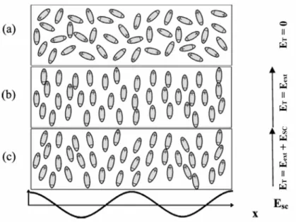
Figure 1.4 Dipolar NLO chromophores reorientation in the total electric field ET. a)
no electric field is applied; b) d.c. external electric field Eext is applied; c) spatially
modulated space charge field ESC is added.
The orientational or birefringence contribution is strictly correlated to the capability of NLO chromophores to align along the total (local) electric field ET, and hence to their
mobility in the amorphous phase of the material. Figure 1.4 qualitatively displays the different alignment of dipolar NLO chromophores for different kinds of ET. From this point of view,
glass transition temperature Tg plays a fundamental role in determining the extent of the PR
together with other features involved with charge transport and in general with all the viscoelastic properties of the materials, to be discussed later (s. Sect. 1.6.1 and Sect. 2).
In the model so far used in order to describe the PR effect, refractive index modulation ∆n is caused by the space charge field ESC through EO effect (1.11). In organic materials
birefringence contribution can lead to a significant enhancement of PR effect which is related to space charge field in a different manner27. It is worth to notice that the poling field acting on the edms of NLO chromophores in a PR material is the total electric field ET given by the
sum of two different electric fields: Eext, the externally applied d.c. electric field (static,
uniform in space), and ESC , the space charge field induced in the material by the interference
pattern (modulated in space) (s. Figure 1.4). These two fields add together in the resulting ET
field that changes both its amplitude and direction over the grating axis (X axis in Figure 1.4), due to the modulation of ESC , whose amplitude varies amidst its extremes +│ESC│ and
-│ESC│. The presence of such a field is responsible for a space periodic reorientation of NLO
chromophores, as illustrated in Figure 1.4 and Figure 1.5. Reorientation dynamics in low-Tg
materials is therefore a fundamental aspect for the comprehension of PR materials and is the topic of extensive studies28,29. In addition, it has been noticed that the global writing speed of a PR grating in an organic material is mainly influenced by the chromophores mobility30. Indeed, molecular reorientation times can vary from picoseconds (e.g., in liquids), up to extremely long times of the order of years (as observed, for instance, in very high Tg polymers
in which a high temperature, T >Tg, poling has been made under the effect of an externally
applied electric field, followed by a rapid temperature quenching). Typical features related to reorientation times are material’s viscosity, molecular dimensions and steric hindrances of NLO chromophores, intermolecular interactions.
The periodic reorientation of the anisotropic units responsible for the NLO effects gives origin to a corresponding periodic modulation of refractive index via a mechanism of orientational birefringence, s. Eq. (1.38).
Figure 1.5 a) Poling total electric field ET is the sum of d.c. external electric field, Eext, and
modulated space charge field, ESC; b) periodic reorientation along x of NLO dipolar chromophores
(dipoles are sketched as arrows) caused by the application of ET; c) orientation of axes and
definitions of angles in a common experimental geometry employed in 2BC or Degenerate Four-Wave Mixing (DFWM) techniques.
In this way, it is possible to recognize two different contributions to the total refractive index modulation ∆n: an electrooptic contribution ∆nEO, related to second order NLO properties (β), and a birefringence contribution ∆nBR, related to edm µ and linear polarizability anisotropy ∆α. Making reference to the previous equations it is possible to sum up all these considerations and to deduce some general rules about molecular features that NLO chromophores must possess in order to exhibit the best PR properties. Here is a list of these requirements:
1) high value of first hyperpolarizability β, in order to maximize EO effect, Eq. (1.39); 2) high value of permanent edm µ, in order to obtain an efficient chromophores
reorientation through the moment of the forces exerted on them by an electric field; an high value of µ is desirable also because of the µ2 dependence of birefringence contribution, Eq. (1.38);
3) high value of linear polarizability anisotropy ∆α, in order to maximize birefringence contribution.
Given the resulting squared dependence on total electric field ET of both contributions
refractive index modulation in organic PR materials as a Kerr effect; otherwise, as concerns inorganic materials, a Pockels effect is recognized31,32. Coherently with this interpretation and with the observed peculiar behaviour of organic amorphous materials, the same group of researchers have subsequently defined a proper molecular figure of merit, FKerr, to be used for
push-pull NLO chromophores. It quantitatively describes and measures the previously listed requirements. Kerr figure of merit is defined as33:
2 1 2 9 Kerr B F M k T µ α µβ ⎡ ∆ ⎤ = ⎢ + ⎥ ⎣ ⎦ (1.40)
in which M is the molecular weight of the NLO chromophore, and kB is the Boltzmann
constant. In the simplest case, that is when NLO chromophores can be considered as “one-dimensional” push-pull moieties, the polarizabilities figuring in (1.40) can be approximated as follows33: 2 2 c eg eg h µ λ α ∆ = , (1.41)
( )
2 2 0 2 6 c eg eg h µ µλ β = ∆ , (1.42)with µeg transition dipole moment, λeg transition wavelength and ∆µ variation of the edm
between the ground state (g) and the excited state (e) in a simple two levels scheme, frequently employed in the modeling of such systems. Calculations made on typical NLO chromophores revealed that the main contribution to PR response is given by the term dependent on ∆α (birefringence contribution up to > 75%), while β-dependent term has poorer relevance (< 25%)31,33. It is important to notice that, at low concentration of NLO moieties in the PR material, a good correlation exists between the isolated chromophore figure of merit
FKerr and the bulk refractive index modulation ∆n. This correlation ceases to remain valid at higher concentrations; actually it has been evidenced in some kinds of chromophores the onset of strong intermolecular interactions (like, for instance, the phenomenon of aggregation in head-to-tail dimers arrangement leading to a neat reduction of the total edm for dimer) that cause the deviation from the behaviour expected on the basis of molecular figure of merit33,34,35. This aspect has not yet been sufficiently explained and is currently the field of extensive studies.
The derivation of analytical expressions that describe the bulk electrooptic and birefringence contributions when poling field is the modulated total electric field ET, is more complicated than in “traditional” purely electrooptic case. While details of such derivation are extensively described elsewhere17, we report here the obtainable expressions for the different contributions of the refractive index modulation. For the birefringence (BR) contribution:
(
)
1 2 1 2 1 2
2 3
2cos sin sin cos cos cos sin sin 2 BR p ext SC n BE E n π ⎡ ϕ α α ϕ α α ϕ α α ⎤ ∆ = ⎢ − + + ⎥ ⎣ ⎦ , (1.43) being 2 2 ( ) 45 B B N k T µ α α⊥ ⎛ ⎞ = − ⎜ ⎟ ⎝ ⎠ & . (1.44)
For the electrooptic (EO) contribution:
(
)
1 2 1 2 1 2
8
cos cos cos 3cos sin sin sin sin EO p ext SC n CE E n π ⎡ ϕ α α ϕ α α ϕ α α ⎤ ∆ = ⎣ + + + ⎦ , (1.45) being 15 B N C k T βµ = . (1.46)
In the previous equations, φ = (90° - Ψ) is the angle between the interference pattern wave vector KJJG and the normal direction to sample surface; Ψ is the tilt angle between sample normal and beams bisector; α1 and α2 are the incidence angles of beam 1 and 2 with respect to normal incidence, respectively. These angles are visualized in Figure 1.5 c) that schematizes the geometrical arrangement commonly employed in 2BC or Degenerate Four-Wave Mixing (DFWM) techniques, frequently used to test and study PR materials2,36. Details on 2BC and on the experimental setup adopted in the present research are given in the following ( s. Sects. 3.6 and 3.7). The Eext
JG
field component aligned along the grating wave vector KJJG results to be E0 = Eextcosφ; it is important to stress the fact that this component must be diverse from zero
the periodic distribution of charges responsible for space charge field ESC. The relations described so far are valid for p polarized beams, i.e. light beams whose electric field lies in a direction parallel to the plane of incidence (the plane made by the radiation propagation direction and a vector normal to the plane of a reflecting surface). Similar relations can be derived for s-polarized beams (even if, in that case, pump and signal beams invert themselves). Some studies have also been conducted in order to verify beams inversion and geometrical relations1,2.
1.5 Photoconductivity (PC)
In order to have PR effect a material must be able to conduct charges, as briefly discussed in the introduction. This capability is obtained making use of photoconductors (PC); in organic PR materials several different types of materials can be used: photoconductive polymers (e.g., PVK, PSX, PPV), low molecular weight glass forming photoconductive molecules, insulating polymer matrices (e.g., polycarbonates, PS, PMMA, polysiloxane) doped with photoconductive monomers (PC monomers are dissolved in inert polymer matrices) or functionalized polymers having pendant groups with charge transport properties. All of them are unipolar photoconductors, that is, conduction takes place involving only one kind of charges (holes or electrons). The large majority of organic PR materials are hole-transporting photoconductors; for this reason in the following we refer only to hole transport. Nevertheless, it is important to remind that some electron transporting and bipolar organic PC materials have been discovered and studied37,38,39. The primary requirement for a PC material is photosensitivity; it means that a phenomenon is present through which charge generation under illumination of the material occurs. Several ways exist to introduce photosensitivity in an organic material; the more exploited one is the addition of species acting as photosensitizer agents whose role is to assist charge photogeneration. The choice of a particular photosensitizer is imposed by the nature of the moieties (molecular species or functional groups, grafted units, repetitive units of a macromolecular chain) designed as charge transport agent in the material and by the desired wavelength sensitivity. Dealing with wavelength sensitivity it is important to remark that, in order to fully exploit the sensitizer agent in the operating wavelength range, sensitizer moiety must exhibit the smaller bandgap (i.e. gap between ground and excited states; it is responsible for the absorption of light and, hence, for photogeneration) among the different components of the photorefractive material. On the other hand, absorption by other components must be avoided in order to minimize the
production of different photochromic gratings. At the same time, optical absorption by the sensitizer must be limited, in order to achieve a neat optical gain.
Several classes of organic molecules have been studied and utilized as sensitizers (e.g. squaraines, phtalocyanines, thiapyrylium salts, perylene dyes, transition metal complexes)40,41,42,43. Other approaches tried to use inorganic agents, like CdS or CdSe semiconductor quantum dots, as sensitizers in order to give hybrid inorganic-organic composites or nanocomposites44,45,46,47.
The most common class of photosensitizers, indeed, is represented by charge transfer complexes (CTC)48 formed by the interaction between electron-donor moieties responsible for
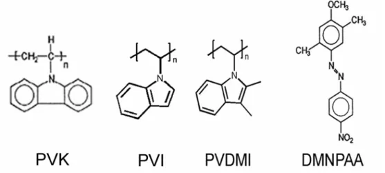
conduction of holes (e.g., electron-rich molecules or polymers, like poly-(N-vinylcarbazole) PVK extensively studied and applied49), and electron-acceptor ones (e.g., molecular species as 2,4,7-trinitro-9-fluorenone TNF, or (2,4,7-trinitro-9-fluorenylidene)malononitrile TNFM, Table 1.1). Besides nitro-derivatives, other photosensitizers have been tested and employed: cyano-derivatives, halogenated compounds, fullerene C6050,51,52,53.
The intermolecular interaction between the donor D and the acceptor A, through the formation of a CTC, results in new absorption bands in the visible or near infrared regions; these bands do not appear in the absorption spectra of both single isolated molecules. The relative ease of formation of such complexes is primarily due to the low ionization potentials ip of electron rich moieties (e.g., the planar carbazole unit).
The mechanism of photogeneration operating in such systems is based on the optical excitation of a CTC; it is usefully schematized (s. Figure 1.6, right) as a three-steps process in a model called coupled charges recombination model:
1. optical excitation of CTC by incident radiation
2. electron transfer from a not-complexed donor species to the excited CTC
3. dissociation of the electron-hole pair and migration through transport molecules. A fundamental role in such a frame is played by the energy stabilization of HOMO level (Highest Occupied Molecular Orbital) of the CTC, with respect to HOMO of the not-complexed donor. This stabilization energy is equal to complexation enthalpy ∆Hc,(s. Figure 1.6, left) whose value is in turn related to the ip of the donor. Molecules whose ip is low are indeed better electron-donors; it means, therefore, that they link more strongly the acceptors to create a CTC. The lower is the value of ip, the higher will be complexation enthalpy. These two quantities rule the rate of the process described in step 2, that is the transfer of an electron
from a donor molecule to an excited CTC. Marcus theory54 predicts for the rate constant KET of the electron transfer reaction:
(
)
(
)
2 0exp exp 4 c ET B H K K b R k T λ λ ⎛ ∆ − ⎞ ⎜ ⎟ = − ∆ − ⎜ ⎟ ⎝ ⎠ (1.47)with K0 and b constants; λ is a parameter called reorganization energy, ∆R is the distance
between reaction centers.
The absorption of a photon by the CTC causes the generation of an electron-hole pair (Frenkel’s exciton); it is necessary to separate this pair so that free charges may rise. This separation process is competing with the corresponding recombination: because of the low values of dielectric permittivity in organic materials, Coulomb interactions between electron and hole are poorly screened, attraction thus leading to charges recombination. This process strongly influences the generation of free charges capable to participate in the transport, thus resulting in a diminished photogeneration efficiency. Quantum efficiency for the photogeneration process η (photogeneration efficiency) is defined as the ratio between the number of photogenerated charges (NPC) and the number of absorbed photons (NAP):
PC AP
N N
Figure 1.6 To the left, scheme displaying the energetic levels of acceptor and donor molecules and the corresponding levels of the CTC formed by the complexation of these two species. Only a simplified representation of the resulting HOMO and LUMO levels of CTC is displayed for clarity, even if more levels are formed, resulting in HOMO2, LUMO2, etc. levels of the CTC. The gap existing between HOMO levels of donor and CTC represents the stabilization energy, or complexation enthalpy, ∆Hc. To the right, the three steps of photogeneration mechanism by a CTC
through its excitation at energy ECT and migration of charges from neighbour donor molecules (s.
text).
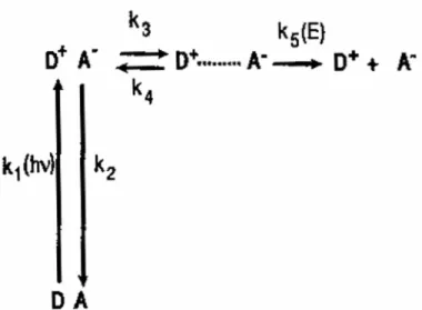
Photogeneration and recombination of charges are usually described by means of a kinetic model55 schematized in Figure 1.7. During the first stage an absorption of light (E =
hν) occurs by the CTC (DA) formed between an electron donor D and an electron-acceptor A.
This event causes DA to change in D+ A-, the excited state; the rate of this process is regulated by the k1 constant. The excited state might eventually decay to ground state with
rate k2 or the charges may separate each other via the jump of a hole (or of an electron) towards an A species (or, respectively, D species), thus forming a separated charges state D+....A-, this process being regulated by the k3 constant. This is a reversible process: the CTC
excited state (D+A-) can be obtained again via coupled recombination (k4). The complete
separation of electron-hole pairs into free charges occurs only when they can efficiently escape their mutual coulomb attraction field: it happens only when an electric field of proper magnitude is externally applied to the sample. The constant regulating this process, k5(E), is
HOMO HOMO LUMO LUMO CTC acceptor donor ∆Hc ECT Space CTC* donor donor (1) (2) (3)
therefore electric field dependent. Charge generation actually can increase under the application of an electric field capable to separate charges; in this way quantum efficiency for charge generation is strongly dependent on applied electric field, increasing as it increases. The dependence of photogeneration efficiency by parameters as temperature T and applied electric field has been described in the frame of a model developed by Onsager56, and subsequently by more complex theories by Noolandi and Hong50,57; trends derived by this models show good agreement with experimental data.
Figure 1.7 Kinetic scheme describing the process of charge generation in a CTC formed by a donor (D) and an acceptor (A) moieties (s. text).
In inorganic materials (crystalline solids) conduction takes place through a transport mechanism based on the band structure of electronic levels, due to periodicity of crystal lattices. In that case “extended” electronic states are involved (states expanding over the entire lattice) and microscopic mobility of charges µ0 is determined by band structure and scattering phenomena due to lattice vibrations (phonons). On the contrary, when organic amorphous material are considered PC is described by means of a hopping mechanism16,58. In this process, charges are said to be exchanged (or to “jump”) among neighbour sites, namely molecular species or functional groups in polymeric chains. It is thus the case of “localized states”. In this frame, holes are therefore cationic radicals -molecules or functional groups positively charged-, while electrons are the corresponding anionic radicals. Transport mechanism could be seen as a series of reversible redox reactions, driven by the applied electric field, in which neutral functional groups or molecules repeatedly transfer an electron to the nearest neighbour radical cation in the direction of the applied electric field. Charge migration involves ionic species (radical cations in the case of hole transport); nevertheless
hopping is not considered an ionic mechanism because matter transport is not involved (ions don’t move). In this description it is assumed that energy distribution of various discrete hopping sites is narrow, that is, the activation energy required for a free charge to jump from one site to the other is approximately the same for all sites. An estimate made by Bässler et
al.59 calculated a mean width of ≈ 0.1 eV for such distribution.
In guest-host systems (s. Sect. 1.6.1) like polymers doped with molecular species, charge transport is a very complex process, its full description remaining a challenge because of the multiplicity of features influencing holes mobility. Energetic disorder degree, dipole moments of the host matrix and guest molecule/s, are only some of the many features taken into consideration in the literature60. A Gaussian Disorder Model (GDM) was introduced in
order to describe the hopping mechanism16,58,59,60,61,62. In this GDM frame it has been shown that the edm of the active donor group, together with edms of other species involved in PC, cannot be ignored. The interactions of the migrating charges (holes) with the edms inside the material leads to the Poole-Frenkel-like equation for the mobility m:
( )
(
1/2)
m(E) m 0 exp SE= (1.49) as a function of the square root of the applied electric field E 63. In a semilogarithmic representation, m(0) is the intercept at E = 0 and S represents the slope of the linear function when E1/2 is reported on the abscissa. A high value of m(0) has been put in relation, in the frame of the GDM61, to a low value of the energetic disorder due to the dispersive interactions of the migrating charges with the donor D molecules. Such a disorder relates to the density of the states (DOS) whose width increases with the disorder. The slope S too is sensitive to the energetic disorder; it has been also related to the geometrical disorder connected to random distribution of the intermolecular distances and orientations among hopping sites. As a general remark, high S values are found for systems characterized by high disorder.
In this quite complex frame it is necessary to consider another important aspect, playing a major role in PC and PR: the presence of traps. Traps are known to be sites in which charges can be blocked for some time, thus limiting or hampering charge migration; they are hopping sites differing from the huge majority of sites: their activation energy, necessary to release charges, is larger than the average value of activation energy of the distribution. In a hole transport photoconductor, traps can be molecular moieties or functional groups in a polymer whose ip is lower with respect to ip of hopping species. Migrating holes (which are the mobile charges in the vast majority of organic PR materials) can incur and be trapped in various different trap sites: molecular impurities accidentally present in the