ScienceDirect
Available online at Available online at www.sciencedirect.comwww.sciencedirect.com
ScienceDirect
Energy Procedia 00 (2017) 000–000
www.elsevier.com/locate/procedia
1876-6102 © 2017 The Authors. Published by Elsevier Ltd.
Peer-review under responsibility of the Scientific Committee of The 15th International Symposium on District Heating and Cooling.
The 15th International Symposium on District Heating and Cooling
Assessing the feasibility of using the heat demand-outdoor
temperature function for a long-term district heat demand forecast
I. Andrić
a,b,c*, A. Pina
a, P. Ferrão
a, J. Fournier
b., B. Lacarrière
c, O. Le Corre
caIN+ Center for Innovation, Technology and Policy Research - Instituto Superior Técnico, Av. Rovisco Pais 1, 1049-001 Lisbon, Portugal bVeolia Recherche & Innovation, 291 Avenue Dreyfous Daniel, 78520 Limay, France
cDépartement Systèmes Énergétiques et Environnement - IMT Atlantique, 4 rue Alfred Kastler, 44300 Nantes, France
Abstract
District heating networks are commonly addressed in the literature as one of the most effective solutions for decreasing the greenhouse gas emissions from the building sector. These systems require high investments which are returned through the heat sales. Due to the changed climate conditions and building renovation policies, heat demand in the future could decrease, prolonging the investment return period.
The main scope of this paper is to assess the feasibility of using the heat demand – outdoor temperature function for heat demand forecast. The district of Alvalade, located in Lisbon (Portugal), was used as a case study. The district is consisted of 665 buildings that vary in both construction period and typology. Three weather scenarios (low, medium, high) and three district renovation scenarios were developed (shallow, intermediate, deep). To estimate the error, obtained heat demand values were compared with results from a dynamic heat demand model, previously developed and validated by the authors.
The results showed that when only weather change is considered, the margin of error could be acceptable for some applications (the error in annual demand was lower than 20% for all weather scenarios considered). However, after introducing renovation scenarios, the error value increased up to 59.5% (depending on the weather and renovation scenarios combination considered). The value of slope coefficient increased on average within the range of 3.8% up to 8% per decade, that corresponds to the decrease in the number of heating hours of 22-139h during the heating season (depending on the combination of weather and renovation scenarios considered). On the other hand, function intercept increased for 7.8-12.7% per decade (depending on the coupled scenarios). The values suggested could be used to modify the function parameters for the scenarios considered, and improve the accuracy of heat demand estimations.
© 2017 The Authors. Published by Elsevier Ltd.
Peer-review under responsibility of the Scientific Committee of The 15th International Symposium on District Heating and Cooling.
Keywords: Heat demand; Forecast; Climate change
Energy Procedia 129 (2017) 575–582
1876-6102 © 2017 The Authors. Published by Elsevier Ltd.
Peer-review under responsibility of the scientific committee of the IV International Seminar on ORC Power Systems. 10.1016/j.egypro.2017.09.209
10.1016/j.egypro.2017.09.209
© 2017 The Authors. Published by Elsevier Ltd.
Peer-review under responsibility of the scientific committee of the IV International Seminar on ORC Power Systems.
1876-6102 Available online at www.sciencedirect.com
ScienceDirect
Energy Procedia 00 (2017) 000–000www.elsevier.com/locate/procedia
1876-6102 © 2017 The Authors. Published by Elsevier Ltd.
Peer-review under responsibility of the scientific committee of the IV International Seminar on ORC Power Systems.
IV International Seminar on ORC Power Systems, ORC2017
13-15 September 2017, Milano, Italy
Intermittent waste heat recovery: Investment profitability of ORC
cogeneration for batch, gas-fired coffee roasting
A. M. Pantaleo
a,b, *, J. Fordham
,b, O. A. Oyewunmi
band C. N. Markides
ba Department of Agro-environmental Sciences, University of Bari, Via Amendola 165/A 70125 Bari, Italy
b Clean Energy Processes (CEP) Laboratory, Department of Chemical Engineering,
Imperial College London, South Kensington Campus, London, SW7 2AZ, UK
Abstract
Coffee roasting is a highly energy intensive process with much of the energy being lost in intermittent cycles as discharged heat from the stack. CHP systems have been investigated to provide heat to the roasting process by a micro gas turbine (MGT). However, much of the heat released in a coffee roaster is from the afterburner that heats up the flue gas to higher temperatures to remove volatile organic compounds and other pollutants. In this paper, a solution to utilising waste heat is assessed through energy and material balances of a rotating drum coffee roasting with partial hot gas recycling. A cost assessment methodology is adopted to compare the profitability of three systems configurations integrated into the process. The case study of a major coffee torrefaction firm with 500 kg/hr production capacity is assumed to carry out the thermo-economic assessment, under the Italian energy framework. The CHP options under investigation are: (i) regenerative topping micro gas turbine (MGT) coupled to the existing modulating gas burner to generate hot air for the roasting process; (ii) intermittent waste heat recovery from the hot flue gas through an organic Rankine cycle (ORC) coupled to a thermal storage buffer. The results show that the profitability of these investments is highly influenced by the natural gas/electricity cost ratio, by the coffee torrefaction production capacity and intermittency level of discharged heat. MGT seems to be more profitable than waste heat recovery via ORC due to the intermittency of the heat source and the relatively high electricity/heat cost ratio.
© 2017 The Authors. Published by Elsevier Ltd.
Peer-review under responsibility of the scientific committee of the IV International Seminar on ORC Power Systems. Keywords: ORC, waste heat recovery, miccro gas turbine, intermittent heat recovery, coffee torrefaction
* Corresponding author. Tel.: +39(0)80.5442869; fax: +30(0)805442830.
E-mail address: [email protected]; [email protected]
Available online at www.sciencedirect.com
ScienceDirect
Energy Procedia 00 (2017) 000–000www.elsevier.com/locate/procedia
1876-6102 © 2017 The Authors. Published by Elsevier Ltd.
Peer-review under responsibility of the scientific committee of the IV International Seminar on ORC Power Systems.
IV International Seminar on ORC Power Systems, ORC2017
13-15 September 2017, Milano, Italy
Intermittent waste heat recovery: Investment profitability of ORC
cogeneration for batch, gas-fired coffee roasting
A. M. Pantaleo
a,b, *, J. Fordham
,b, O. A. Oyewunmi
band C. N. Markides
ba Department of Agro-environmental Sciences, University of Bari, Via Amendola 165/A 70125 Bari, Italy
b Clean Energy Processes (CEP) Laboratory, Department of Chemical Engineering,
Imperial College London, South Kensington Campus, London, SW7 2AZ, UK
Abstract
Coffee roasting is a highly energy intensive process with much of the energy being lost in intermittent cycles as discharged heat from the stack. CHP systems have been investigated to provide heat to the roasting process by a micro gas turbine (MGT). However, much of the heat released in a coffee roaster is from the afterburner that heats up the flue gas to higher temperatures to remove volatile organic compounds and other pollutants. In this paper, a solution to utilising waste heat is assessed through energy and material balances of a rotating drum coffee roasting with partial hot gas recycling. A cost assessment methodology is adopted to compare the profitability of three systems configurations integrated into the process. The case study of a major coffee torrefaction firm with 500 kg/hr production capacity is assumed to carry out the thermo-economic assessment, under the Italian energy framework. The CHP options under investigation are: (i) regenerative topping micro gas turbine (MGT) coupled to the existing modulating gas burner to generate hot air for the roasting process; (ii) intermittent waste heat recovery from the hot flue gas through an organic Rankine cycle (ORC) coupled to a thermal storage buffer. The results show that the profitability of these investments is highly influenced by the natural gas/electricity cost ratio, by the coffee torrefaction production capacity and intermittency level of discharged heat. MGT seems to be more profitable than waste heat recovery via ORC due to the intermittency of the heat source and the relatively high electricity/heat cost ratio.
© 2017 The Authors. Published by Elsevier Ltd.
Peer-review under responsibility of the scientific committee of the IV International Seminar on ORC Power Systems. Keywords: ORC, waste heat recovery, miccro gas turbine, intermittent heat recovery, coffee torrefaction
* Corresponding author. Tel.: +39(0)80.5442869; fax: +30(0)805442830.
576 A. M. Pantaleo et al. / Energy Procedia 129 (2017) 575–582
2 Pantaleo A./ Energy Procedia 00 (2017) 000–000 Nomenclature
Symbols
VOCs volatile organic compounds NG natural gas
CHP combined heat and power MGT micro gas turbine ORC organic Rankine cycle PM particulate matter TES Thermal Energy Storage
𝑄𝑄 thermal power recovered from cycle (kJ/s) 𝑚𝑚 gas turbine mass flow rate (kg/s)
ℎ!"#$ enthalpy of flue gas in drum (kJ/kg) ℎ!" enthalpy of flue gas at MGT outlet (kJ/kg) R heat capacity of flue gas (J/kg K)
ρ density of flue gas (kg/Nm3) 𝑇𝑇!" T pressurised water in the TES (°C) 𝑚𝑚!" mass of water in the TES (kg)
𝑚𝑚!" mass flow rate of water in TES (kg/s) 𝑐𝑐!,!" specific heat capacity of pressurised water in TES (J/kg°C)
𝑄𝑄!" intermittent rate of heat transfer from flue gas to TES (kJ/s)
𝑄𝑄!"# constant heat transfer rate from pressurised water to ORC (kJ/s)
𝑇𝑇!",!"##$%supply temperature of water in TES (°C) 𝑇𝑇!",!"#$!%return temperature of water in TES (°C) 𝑊𝑊!"# net power output from ORC system (kW) 𝜂𝜂!"# efficiency of ORC working fluid (%) 𝑃𝑃!"#$ ORC working fluid evaporator limits (bar) 𝑃𝑃!"#$ ORC working fluid condenser limits (bar) LHV lower heating value
1. Introduction
Coffee roasting is a growing industry with 6.7 billion kg of coffee being roasted every year. It is highly energy intensive, requiring 11.2 x 10¹² kJ/fuel energy annually, with 75% of the energy being wasted as heat through the
stack [1,2]. Around 50% of industrial processes such as coffee roasting, sintering, dairy production and pharmaceuticals use batch processes to improve the quality and consistency of the products [3-6]. The drawback to batch processes is the substantial amount of waste heat emitted intermittently, preventing conventional methods from being used for recovery. Heat integration of batch processes across industries have been investigated in the literature to reduce energy use [7-9]. Heat storage system have proven to be successful in recovering and reusing the heat as seen in further investigations [10-15].
The operation of batch gas-fired coffee roasters equipped with afterburners is well known and widely described in literature [16-19]. The methods include a heating air process, generally by means of a modulating gas burner, followed by passing the hot air through the coffee beans passively with a batch process that lasts around 10 minutes. The hot air usually travels from the roasting chamber through an afterburner to remove the VOCs and carbon monoxide and is finally discharged at high temperature into the atmosphere. This single-pass roasting method is often substituted to a semi-closed loop where part of the roaster gases are recycled and mixed to the hot air flow in order to roast the beans with the desired time-temperature curve. A big challenge for roasting is to rapidly heat the air before introducing it into the batch. To achieve this rapid heating, the roasters use a very energy intensive and quite low efficiency process. The afterburner is also quite energy intensive and releases the final gas at a very high temperature. In this paper, energy and material balances of a rotating drum coffee roasting with partial hot gas recycling and costs assessment methodologies are adopted to compare the profitability of three cogeneration systems integrated into the process. The case study of a major coffee processing firm with 500 kg/hr production capacity and the Italian electricity/NG cost scenario are assumed to carry out the thermo-economic assessment. The CHP options under investigation are: (i) regenerative topping MGT coupled to the existing modulating gas burner to generate hot air for the roasting process; (ii) fluctuating waste heat recovery from the hot flue gas through an ORC with a thermal storage buffer; (. MGTs are the typical choice for implementing CHP systems in these types of roasters, therefore ORCs are investigated to determine their feasibility of utilising more waste heat form the afterburner. The sensitivity of investment profitability to the main techno-economic process parameters and in particular to the daily roasting operating hours and electricity/NG cost ratio is presented, to derive useful insights about the key factors influencing the feasibility of such investments for coffee roasting firms.
Pantaleo A./ Energy Procedia 00 (2017) 000–000 3
2. The coffee roasting process under investigation
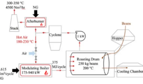
The coffee roasting process is a chemical process that turns green coffee beans into beans that can be ground, brewed and consumed with a complex aroma and flavor. For a batch coffee roaster, the roasting happens in cycles as the green coffee beans enter the roasting drum and are heated to the desired temperature of 200-250 °C before being transferred to a cooling chamber [20,21]. A cycle lasts 10 to 20 minutes depending on the desired degree of roasting. The roasting drum is a horizontal rotating chamber that rotates at a specified speed to induce mixing without the beans getting stuck to the walls from centrifugal forcing. Hot air is generated in a combustion chamber, usually fueled by NG, and passes through the roasting drum, heating the beans to the desired temperature. The first stage of coffee roasting involves the evaporation of water from the bean when it reaches temperatures between 160 °C and 190 °C [18,22-24]. After water removal, the bean undergoes of set of chemical reactions in pyrolysis, which give the coffee its final flavor and aroma at a temperature of 200-250 °C. During pyrolysis, there is also a release of volatile organic compounds, carbon dioxide, and particulate matter from the roasted chaff that are added to the flue gas in the roasting drum. When too many volatiles are released from the bean at temperature higher than 200 °C, the aroma of the bean can decrease and the resulting product becomes bitter and undesirable. For this reason, the temperature gradient during the process must be constant in order to achieve a uniform and gradual heating of the beans from the outside to the center. This is done by means of a modulating boiler that can control the output of heat into the roasting drum. The beans are then sprayed with water which turns to steam upon heat absorption, halting the roasting process of the beans. They are then transferred to a cooling chamber where they are continuously stirred as cool air is blown on them to bring their temperature down to ambient air conditions. Some of the flue gas is returned to the combustion chamber at 180-230 °C through a heat exchanger to utilize some of the waste heat and increase the efficiency of the burner. For the rest of the flue gases leaving the roasting drum, the VOCs, PM and CO2 must be
removed before being emitted to the environment to comply with air quality standards. The flue gas goes through a cyclone to remove particulate and then an afterburner to combust pollutants that are released from the beans during the roasting phase and is then finally released through a chimney into the atmosphere at temperatures between 300-350 °C.
Due to the nature of the batch coffee roasting process, waste heat is released intermittently at the end of each 10-min cycle, with a discharge duration of about 15 seconds. This intermittency prevents a constant flow of energy to recover and reutilise in systems such as an ORC. This can be done using a thermal storage system, either sensible heat thermal storage or latent heat thermal storage. Sensible heat storage systems are most common and use a medium such as pressurized water to store the generated energy from the intermittent source through a heat exchanger. As the flue gas passes through the heat exchanger, its temperature drops, causing a potential issue of fouling. The VOCs and other compounds in the flue gas could condense on the heat exchanger, lowering the efficiency of the heat transfer. The optimal size of the thermal storage tank must also be determined considering the intermittent heat addition and constant release to the ambient air.
The production site being investigated is a large coffee roasting firm that has roasting capacity of 500kg/hr. The firm operates 6 hours per day and 1,560 hours per year. There are two torrefaction units that roast 250 kg of beans per cycle with each cycle lasting 10 minutes. The modulating boiler and afterburner are fueled by NG. Each cycle requires 1.5 MJ of natural gas fuel per kg of beans, or 375 MJ per cycle. With the firm operating at 6 hours per day and 5 days a week, it requires 7020 GJ of natural gas and 800 MWh of electricity per year. The modulating boiler operates in the range 175-940 kW. The temperature of the exhaust gas from the stack is in the range 300-350 °C and the flow rate is 4500 Nm3/hr. This hot air flow rate is assumed constant through the system. A flow chart of the
proposed torrefaction process is shown in Fig 1.
3. The scenarios under investigation
The roasting process is carried out at a relatively low temperature, hence it is possible to improve the overall efficiency recovering thermal energy from a topping MGT in cogenerative configuration or recovering the thermal energy content of the flue gas exiting the afterburner section via an ORC, as described in the following.
A. M. Pantaleo et al. / Energy Procedia 129 (2017) 575–582 577 2 Pantaleo A./ Energy Procedia 00 (2017) 000–000
Nomenclature Symbols
VOCs volatile organic compounds NG natural gas
CHP combined heat and power MGT micro gas turbine ORC organic Rankine cycle PM particulate matter TES Thermal Energy Storage
𝑄𝑄 thermal power recovered from cycle (kJ/s) 𝑚𝑚 gas turbine mass flow rate (kg/s)
ℎ!"#$ enthalpy of flue gas in drum (kJ/kg) ℎ!" enthalpy of flue gas at MGT outlet (kJ/kg) R heat capacity of flue gas (J/kg K)
ρ density of flue gas (kg/Nm3) 𝑇𝑇!" T pressurised water in the TES (°C) 𝑚𝑚!" mass of water in the TES (kg)
𝑚𝑚!" mass flow rate of water in TES (kg/s) 𝑐𝑐!,!" specific heat capacity of pressurised water in TES (J/kg°C)
𝑄𝑄!" intermittent rate of heat transfer from flue gas to TES (kJ/s)
𝑄𝑄!"# constant heat transfer rate from pressurised water to ORC (kJ/s)
𝑇𝑇!",!"##$%supply temperature of water in TES (°C) 𝑇𝑇!",!"#$!%return temperature of water in TES (°C) 𝑊𝑊!"# net power output from ORC system (kW) 𝜂𝜂!"# efficiency of ORC working fluid (%) 𝑃𝑃!"#$ ORC working fluid evaporator limits (bar) 𝑃𝑃!"#$ ORC working fluid condenser limits (bar) LHV lower heating value
1. Introduction
Coffee roasting is a growing industry with 6.7 billion kg of coffee being roasted every year. It is highly energy intensive, requiring 11.2 x 10¹² kJ/fuel energy annually, with 75% of the energy being wasted as heat through the
stack [1,2]. Around 50% of industrial processes such as coffee roasting, sintering, dairy production and pharmaceuticals use batch processes to improve the quality and consistency of the products [3-6]. The drawback to batch processes is the substantial amount of waste heat emitted intermittently, preventing conventional methods from being used for recovery. Heat integration of batch processes across industries have been investigated in the literature to reduce energy use [7-9]. Heat storage system have proven to be successful in recovering and reusing the heat as seen in further investigations [10-15].
The operation of batch gas-fired coffee roasters equipped with afterburners is well known and widely described in literature [16-19]. The methods include a heating air process, generally by means of a modulating gas burner, followed by passing the hot air through the coffee beans passively with a batch process that lasts around 10 minutes. The hot air usually travels from the roasting chamber through an afterburner to remove the VOCs and carbon monoxide and is finally discharged at high temperature into the atmosphere. This single-pass roasting method is often substituted to a semi-closed loop where part of the roaster gases are recycled and mixed to the hot air flow in order to roast the beans with the desired time-temperature curve. A big challenge for roasting is to rapidly heat the air before introducing it into the batch. To achieve this rapid heating, the roasters use a very energy intensive and quite low efficiency process. The afterburner is also quite energy intensive and releases the final gas at a very high temperature. In this paper, energy and material balances of a rotating drum coffee roasting with partial hot gas recycling and costs assessment methodologies are adopted to compare the profitability of three cogeneration systems integrated into the process. The case study of a major coffee processing firm with 500 kg/hr production capacity and the Italian electricity/NG cost scenario are assumed to carry out the thermo-economic assessment. The CHP options under investigation are: (i) regenerative topping MGT coupled to the existing modulating gas burner to generate hot air for the roasting process; (ii) fluctuating waste heat recovery from the hot flue gas through an ORC with a thermal storage buffer; (. MGTs are the typical choice for implementing CHP systems in these types of roasters, therefore ORCs are investigated to determine their feasibility of utilising more waste heat form the afterburner. The sensitivity of investment profitability to the main techno-economic process parameters and in particular to the daily roasting operating hours and electricity/NG cost ratio is presented, to derive useful insights about the key factors influencing the feasibility of such investments for coffee roasting firms.
Pantaleo A./ Energy Procedia 00 (2017) 000–000 3
2. The coffee roasting process under investigation
The coffee roasting process is a chemical process that turns green coffee beans into beans that can be ground, brewed and consumed with a complex aroma and flavor. For a batch coffee roaster, the roasting happens in cycles as the green coffee beans enter the roasting drum and are heated to the desired temperature of 200-250 °C before being transferred to a cooling chamber [20,21]. A cycle lasts 10 to 20 minutes depending on the desired degree of roasting. The roasting drum is a horizontal rotating chamber that rotates at a specified speed to induce mixing without the beans getting stuck to the walls from centrifugal forcing. Hot air is generated in a combustion chamber, usually fueled by NG, and passes through the roasting drum, heating the beans to the desired temperature. The first stage of coffee roasting involves the evaporation of water from the bean when it reaches temperatures between 160 °C and 190 °C [18,22-24]. After water removal, the bean undergoes of set of chemical reactions in pyrolysis, which give the coffee its final flavor and aroma at a temperature of 200-250 °C. During pyrolysis, there is also a release of volatile organic compounds, carbon dioxide, and particulate matter from the roasted chaff that are added to the flue gas in the roasting drum. When too many volatiles are released from the bean at temperature higher than 200 °C, the aroma of the bean can decrease and the resulting product becomes bitter and undesirable. For this reason, the temperature gradient during the process must be constant in order to achieve a uniform and gradual heating of the beans from the outside to the center. This is done by means of a modulating boiler that can control the output of heat into the roasting drum. The beans are then sprayed with water which turns to steam upon heat absorption, halting the roasting process of the beans. They are then transferred to a cooling chamber where they are continuously stirred as cool air is blown on them to bring their temperature down to ambient air conditions. Some of the flue gas is returned to the combustion chamber at 180-230 °C through a heat exchanger to utilize some of the waste heat and increase the efficiency of the burner. For the rest of the flue gases leaving the roasting drum, the VOCs, PM and CO2 must be
removed before being emitted to the environment to comply with air quality standards. The flue gas goes through a cyclone to remove particulate and then an afterburner to combust pollutants that are released from the beans during the roasting phase and is then finally released through a chimney into the atmosphere at temperatures between 300-350 °C.
Due to the nature of the batch coffee roasting process, waste heat is released intermittently at the end of each 10-min cycle, with a discharge duration of about 15 seconds. This intermittency prevents a constant flow of energy to recover and reutilise in systems such as an ORC. This can be done using a thermal storage system, either sensible heat thermal storage or latent heat thermal storage. Sensible heat storage systems are most common and use a medium such as pressurized water to store the generated energy from the intermittent source through a heat exchanger. As the flue gas passes through the heat exchanger, its temperature drops, causing a potential issue of fouling. The VOCs and other compounds in the flue gas could condense on the heat exchanger, lowering the efficiency of the heat transfer. The optimal size of the thermal storage tank must also be determined considering the intermittent heat addition and constant release to the ambient air.
The production site being investigated is a large coffee roasting firm that has roasting capacity of 500kg/hr. The firm operates 6 hours per day and 1,560 hours per year. There are two torrefaction units that roast 250 kg of beans per cycle with each cycle lasting 10 minutes. The modulating boiler and afterburner are fueled by NG. Each cycle requires 1.5 MJ of natural gas fuel per kg of beans, or 375 MJ per cycle. With the firm operating at 6 hours per day and 5 days a week, it requires 7020 GJ of natural gas and 800 MWh of electricity per year. The modulating boiler operates in the range 175-940 kW. The temperature of the exhaust gas from the stack is in the range 300-350 °C and the flow rate is 4500 Nm3/hr. This hot air flow rate is assumed constant through the system. A flow chart of the
proposed torrefaction process is shown in Fig 1.
3. The scenarios under investigation
The roasting process is carried out at a relatively low temperature, hence it is possible to improve the overall efficiency recovering thermal energy from a topping MGT in cogenerative configuration or recovering the thermal energy content of the flue gas exiting the afterburner section via an ORC, as described in the following.
578 4 Pantaleo A./ Energy Procedia 00 (2017) 000–000 A. M. Pantaleo et al. / Energy Procedia 129 (2017) 575–582
3.1. Case Study 1: Regenerative CHP-MGT
A possible solution where a topping MGT is installed before the fresh air inlet is reported in Fig. 2. Therefore the MGT exhaust gas is mixed with the recirculated stream and driven to the furnace, where the temperature is adjusted by means of the existing burner before entering the roasting drum. Assuming that the roasting process is carried out at average temperature of 200°C and a typical exhaust gas temperature of a regenerative gas turbine is 270°C the heat recovered can be calculated from:
𝑄𝑄 = 𝑚𝑚(ℎ!"− ℎ!"#$) (1)
where 𝑄𝑄 is the heat recovered; 𝑚𝑚 is the gas turbine exhaust gas flow rate; ℎ!" is the enthalpy of the flue gas at the gas turbine outlet temperature; hdrum is the enthalpy of the flue gas at the drum temperature
Assuming the data of a commercial 200 kWe MGT, with exhaust gas flow rate of 1.3 kg/s and outlet temperature 270°C, and assuming the flue gas composition of Table 1, the heat recovered Q is 58.32 MJ in a 10 min cycle.
Assuming a heat demand of 1.5 MJ/kg of green beans and a processed mass of 250 kg, the overall heat required per cycle is 375 MJ. The MGT gas flow rate of about 3700 Nm3/h is coherent with the flow rate discharged into atmosphere in a commercial roasting process, which means a minor perturbation to the original process.
Fig. 1. Flow chart of the coffee torrefaction process. Fig. 2. Schematic of CHP-MGT in Case Study 1: Electricity from the MGT is fed to the grid or on site consumed and cogenerated heat is used for torrefaction process.
3.2. Case Study 2: Waste-heat recovery via ORC
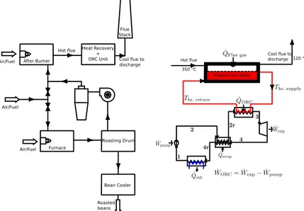
Another viable option for the recovery of waste heat from the coffee torrefaction process is via an ORC system. The torrefaction process generally lasts 10 minutes after which the ‘torrefied’ coffee is extracted and the torrefaction air with coffee peel is discharged to a post burner. In the post burner, the coffee peel is further burnt to avoid emissions of coffee peels and the eventual flue gas exits the after-burner at around 350 °C and at a flowrate of 4,500 Nm3/h;
the flue gas is discharged for a duration of about 15 seconds. Due to the intermittent nature of the flue gas discharge, a thermal energy storage system (TES) in the form of a pressurized-water loop (it is also possible to use a hot-oil loop here) is employed to recover the discharged heat from the flue gas; the flue gas is then discharged to the environment at a lower temperature of 120 °C. This pressurized-water loop acts as the heat source to the ORC system, ensuring a constant availability of heat to the ORC system. The schematic of the coffee torrefaction process with the ORC power system is shown in Fig. 3. A temporal energy balance around the heat recovery loop is described in Eqns (2) and (3), where 𝑇𝑇!", 𝑚𝑚!" and 𝑐𝑐!,!" are the temperature, mass and specific heat capacity of the pressurized-water in the heat recovery loop and 𝑄𝑄!"(𝑡𝑡) is the (intermittent) rate of heat transfer from the flue gas to the heat recovery loop. 𝑄𝑄!"# is the (constant) heat transfer rate from the pressurized-water stream to the ORC working fluid in the ORC evaporator. The thermal storage system is designed (by suitably modifying 𝑚𝑚!" and 𝑚𝑚!") such that the constant temperatures of the pressurized water are 𝑇𝑇!",!"##$%= 120 °C and 𝑇𝑇!",!"#$!%= 90 °C, and supplying ~350 kW to the ORC.. The ORC system configuration is shown in Fig. 4; the system features an extra heat exchanger (the recuperator) to improve its thermal efficiency and power output. In all the heat exchangers, the minimum pinch temperature difference is assumed to be 10 °C, with all cycle processes assumed to be taking place at subcritical pressures due to the low heat source temperature.
Pantaleo A./ Energy Procedia 00 (2017) 000–000 5
Table 1. Composition of flue gas (mass %)
Composition From MG From torrefaction
CO2 2.89% 12.58% H20 3.56% 2.99% N2 73.71% 71.08% O2 18.55% 3.64% AR 1.29% 1.25% R [J/kgK] 318.49 291.54 ρo [kg/Nm3] 1,15 1,26 𝑚𝑚!"𝑐𝑐!,!"d𝑇𝑇d𝑡𝑡!"= 𝑚𝑚!"𝑐𝑐!,!" 𝑇𝑇!",!"#$!%− 𝑇𝑇!",!"##$% + 𝑄𝑄!"(𝑡𝑡) (2) 𝑄𝑄!"#= 𝑚𝑚!"𝑐𝑐!,!" 𝑇𝑇!",!"##$%− 𝑇𝑇!",!"#$!% (3)
The ORC heat sink is assumed to be cooling water supplied at a temperature of 20 °C and discharged at a temperature of 30 °C while the isentropic efficiencies of the pump and expander are assumed to be 85% and 75% respectively. A few of the common ORC working fluids were compared, and at a supply temperature of 120 °C, the ORC systems delivers in excess of 32 kWe while it delivers around 75 kWe at a supply temperature of 150 °C. However, as the input energy to the TES (and hence to the ORC) is fixed and dependent on the intermittency of hot flue gas discharge during the torrefaction process, increasing 𝑇𝑇!",!"##$% from 120°C to 150°C and consequently the TES size from 350 kWt to 700 kWt and the ORC size from 32 to 75 kWe reduces correspondently the operating hours and increases the investment cost (both the expander and the heat exchanger sizes are doubled), while the electric energy output remains quite constant.
Fig. 3. Case Study 2: Waste heat recovery form flue gas via the organic Rankine cycle (ORC) system: LEFT – Schematic of coffee torrefaction process showing heat recovery and ORC power generating unit; RIGHT – Schematic of pressurized-water heat recovery and recuperative ORC
For this reason, even though the conversion efficiency and maximum power output are higher for the case with a supply temperature of 150°C, it appears clear that the most profitable option is the one that minimizes the installed ORC size and hence the investment cost, i.e., the 120°C supply temperature case. Hence in the profitability analysis, the scenario of 120°C supply temperature and ~30 kWe is taken. The option of larger ORC could be however of interest if a further (and low cost) heat source is available, to integrate the intermittent heat stream fed to the TES, in order to increase the capacity factor of the ORC. The inclusion of a recuperator in the ORC system is also seen to improve its efficiency as up to 200 kW of heat is ‘internally recovered’ within the ORC system.
A. M. Pantaleo et al. / Energy Procedia 129 (2017) 575–582 579 4 Pantaleo A./ Energy Procedia 00 (2017) 000–000
3.1. Case Study 1: Regenerative CHP-MGT
A possible solution where a topping MGT is installed before the fresh air inlet is reported in Fig. 2. Therefore the MGT exhaust gas is mixed with the recirculated stream and driven to the furnace, where the temperature is adjusted by means of the existing burner before entering the roasting drum. Assuming that the roasting process is carried out at average temperature of 200°C and a typical exhaust gas temperature of a regenerative gas turbine is 270°C the heat recovered can be calculated from:
𝑄𝑄 = 𝑚𝑚(ℎ!"− ℎ!"#$) (1)
where 𝑄𝑄 is the heat recovered; 𝑚𝑚 is the gas turbine exhaust gas flow rate; ℎ!" is the enthalpy of the flue gas at the gas turbine outlet temperature; hdrum is the enthalpy of the flue gas at the drum temperature
Assuming the data of a commercial 200 kWe MGT, with exhaust gas flow rate of 1.3 kg/s and outlet temperature 270°C, and assuming the flue gas composition of Table 1, the heat recovered Q is 58.32 MJ in a 10 min cycle.
Assuming a heat demand of 1.5 MJ/kg of green beans and a processed mass of 250 kg, the overall heat required per cycle is 375 MJ. The MGT gas flow rate of about 3700 Nm3/h is coherent with the flow rate discharged into atmosphere in a commercial roasting process, which means a minor perturbation to the original process.
Fig. 1. Flow chart of the coffee torrefaction process. Fig. 2. Schematic of CHP-MGT in Case Study 1: Electricity from the MGT is fed to the grid or on site consumed and cogenerated heat is used for torrefaction process.
3.2. Case Study 2: Waste-heat recovery via ORC
Another viable option for the recovery of waste heat from the coffee torrefaction process is via an ORC system. The torrefaction process generally lasts 10 minutes after which the ‘torrefied’ coffee is extracted and the torrefaction air with coffee peel is discharged to a post burner. In the post burner, the coffee peel is further burnt to avoid emissions of coffee peels and the eventual flue gas exits the after-burner at around 350 °C and at a flowrate of 4,500 Nm3/h;
the flue gas is discharged for a duration of about 15 seconds. Due to the intermittent nature of the flue gas discharge, a thermal energy storage system (TES) in the form of a pressurized-water loop (it is also possible to use a hot-oil loop here) is employed to recover the discharged heat from the flue gas; the flue gas is then discharged to the environment at a lower temperature of 120 °C. This pressurized-water loop acts as the heat source to the ORC system, ensuring a constant availability of heat to the ORC system. The schematic of the coffee torrefaction process with the ORC power system is shown in Fig. 3. A temporal energy balance around the heat recovery loop is described in Eqns (2) and (3), where 𝑇𝑇!", 𝑚𝑚!" and 𝑐𝑐!,!" are the temperature, mass and specific heat capacity of the pressurized-water in the heat recovery loop and 𝑄𝑄!"(𝑡𝑡) is the (intermittent) rate of heat transfer from the flue gas to the heat recovery loop. 𝑄𝑄!"# is the (constant) heat transfer rate from the pressurized-water stream to the ORC working fluid in the ORC evaporator. The thermal storage system is designed (by suitably modifying 𝑚𝑚!" and 𝑚𝑚!") such that the constant temperatures of the pressurized water are 𝑇𝑇!",!"##$%= 120 °C and 𝑇𝑇!",!"#$!%= 90 °C, and supplying ~350 kW to the ORC.. The ORC system configuration is shown in Fig. 4; the system features an extra heat exchanger (the recuperator) to improve its thermal efficiency and power output. In all the heat exchangers, the minimum pinch temperature difference is assumed to be 10 °C, with all cycle processes assumed to be taking place at subcritical pressures due to the low heat source temperature.
Pantaleo A./ Energy Procedia 00 (2017) 000–000 5
Table 1. Composition of flue gas (mass %)
Composition From MG From torrefaction
CO2 2.89% 12.58% H20 3.56% 2.99% N2 73.71% 71.08% O2 18.55% 3.64% AR 1.29% 1.25% R [J/kgK] 318.49 291.54 ρo [kg/Nm3] 1,15 1,26 𝑚𝑚!"𝑐𝑐!,!"d𝑇𝑇!"d𝑡𝑡 = 𝑚𝑚!"𝑐𝑐!,!" 𝑇𝑇!",!"#$!%− 𝑇𝑇!",!"##$% + 𝑄𝑄!"(𝑡𝑡) (2) 𝑄𝑄!"#= 𝑚𝑚!"𝑐𝑐!,!" 𝑇𝑇!",!"##$%− 𝑇𝑇!",!"#$!% (3)
The ORC heat sink is assumed to be cooling water supplied at a temperature of 20 °C and discharged at a temperature of 30 °C while the isentropic efficiencies of the pump and expander are assumed to be 85% and 75% respectively. A few of the common ORC working fluids were compared, and at a supply temperature of 120 °C, the ORC systems delivers in excess of 32 kWe while it delivers around 75 kWe at a supply temperature of 150 °C. However, as the input energy to the TES (and hence to the ORC) is fixed and dependent on the intermittency of hot flue gas discharge during the torrefaction process, increasing 𝑇𝑇!",!"##$% from 120°C to 150°C and consequently the TES size from 350 kWt to 700 kWt and the ORC size from 32 to 75 kWe reduces correspondently the operating hours and increases the investment cost (both the expander and the heat exchanger sizes are doubled), while the electric energy output remains quite constant.
Fig. 3. Case Study 2: Waste heat recovery form flue gas via the organic Rankine cycle (ORC) system: LEFT – Schematic of coffee torrefaction process showing heat recovery and ORC power generating unit; RIGHT – Schematic of pressurized-water heat recovery and recuperative ORC
For this reason, even though the conversion efficiency and maximum power output are higher for the case with a supply temperature of 150°C, it appears clear that the most profitable option is the one that minimizes the installed ORC size and hence the investment cost, i.e., the 120°C supply temperature case. Hence in the profitability analysis, the scenario of 120°C supply temperature and ~30 kWe is taken. The option of larger ORC could be however of interest if a further (and low cost) heat source is available, to integrate the intermittent heat stream fed to the TES, in order to increase the capacity factor of the ORC. The inclusion of a recuperator in the ORC system is also seen to improve its efficiency as up to 200 kW of heat is ‘internally recovered’ within the ORC system.
580 A. M. Pantaleo et al. / Energy Procedia 129 (2017) 575–582
6 Pantaleo A./ Energy Procedia 00 (2017) 000–000
4. Profitability and sensitivity analysis
The annual electricity demand of the firm results of about 800 MWh with a total cost of supply of 150 kEur/year and a correspondent avoided cost for on site generated electricity of 150 Eur/MWh. The NG supply cost is 0.385 Eur/Nm3 with a LHV of 10.46 kWh/Nm3. O&M costs for all cases are assumed of 12 Eur/MWh of electricity generated. With these assumptions, and on the basis of the energy performance and investment/operational costs of each case study, a preliminary cost/benefit analysis is presented. Investment costs are assumed from manufacturers of MGT [14] and small scale ORC [15]. Table 2 reports the electricity output in each 10-min cycle and the correspondent NG consumption and savings for the three case studies. On the basis of fuel costs, O&M costs and investment costs, the economic balances are reported in Table 3, assuming the torrefaction capacity rate of the firm under investigation (36 cycles per day and 9,360 cycles per year). As can be seen, at the relatively low production capacity of the proposed case study, and with the assumed electricity and NG costs, the investment profitability is quite low.
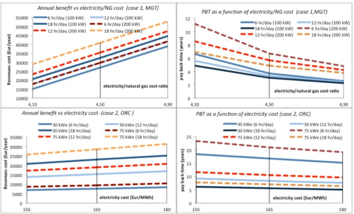
The results assume that the CHP plant operates only during the coffee torrefaction process to avoid discharged heat from cogeneration. This operation influences the investment profitability, that increases when operating the CHP plant baseload and in net metering to the grid, in order to produce, on a yearly basis, the same amount of electricity consumed by the firm. With the assumed hypothesis, the highest profitability for case study 1 is achieved when the CHP electricity output on a yearly basis equals the on site electricity demand of the firm. In order to evaluate the influence of the electricity/natural gas cost ratio and of the torrefaction production capacity (and consequently heat demand for the process), a sensitivity of investment profitability of the case 1 (MGT in CHP mode) is proposed in Figure 4. The two sizes of 100 and 200 kW are compared (with operating hours of 8000 and 4000 h/year respectively) at different heat demand intensity (which correspond to different production capacity intensity rates, and different cycles per year). As can be seen, at high electricity/natural gas cost ratio and high production capacity intensity, the profitability of the investment increases, and the small scale MGT appears more profitable since it can better match the electricity demand of the firm operating for 8,000 hr/year baseload instead of 4,000 hr/year of the 200 kW size CHP. In the same figure, the sensitivity of investment profitability for case 2 (ORC) is reported, as a function of the torrefaction production capacity (respectively 6.12 and 18 working hours/day) and avoided cost of electricity, and for the two ORC sizes of 30 and 75 kWe. As can be seen, when increasing the operating hours of the MGT (case 1), the investment profitability increases and exceeds the one of the ORC, which is highly influenced by the production capacity.
Table 2. Main energy balance results for the proposed case studies referred to a torrefaction cycle time of 10 min.
Table 3. Main economic input data and results for the proposed case studies referred to a torrefaction cycle time of 10 min.
Case 1 Case 2 Case 1 Case 2
Plant size kWe 200 30 Saving Eur/cycle 5.65 0.75
NG saved Nm3/cycle 1.65 - Fuel Cost Eur/cycle 4.35
-Electricity generated kWh/cycle 33.33 5 O&M Cost Eur/cycle 0.4 0.06
NG consumption Nm3/cycle 11.31 - total Cost Eur/cycle 4.75 0.06
Balance Eur/cycle 0.9 0.69
Investment (Eur) 200,000 120,000
Pay back cycles 222,222 173,913
Pay back time (years) (6 hr/day operation) 23.7 18.6
Pantaleo A./ Energy Procedia 00 (2017) 000–000 7
Fig. 4. Top: Profitability analysis results for Case Study 1 (as a function of electricity/NG cost and CHP size (100 and 200 kW respectively); the
CHP operates baseload at 8,000-4,000 hours/year (100-200 kW size) and the heat demand is varied (1000, 2000, 3000 hr/year). Bottom:
profitability analysis results for Case Study 2 (as a function of electricity cost, proces working hours (hr/day) and ORC size (30 and 75 kWe r)
4. Conclusions
In this paper, energy balances of a rotating drum coffee roasting with partial hot gas recycling and costs assessment methodologies are adopted to compare the profitability of three cogeneration systems integrated into the torrefaction process. The case study of a major coffee processing firm with 500 kg/hr production capacity is assumed to carry out the thermo-economic assessment. The CHP options under investigation are: (i) regenerative topping MGT coupled to the existing modulating gas burner to generate hot air for the roasting process and electricity for on site consumption; (ii) fluctuating waste heat recovery from the hot flue gas via a TES and organic Rankine cycle (ORC). MGTs are the typical choice for implementing CHP systems in these types of roasters, therefore ORCs are investigated to determine their feasibility of utilising more waste heat form the afterburner. The techno-economic results report a PBT for ORC ranging between 5 and 6 years in case of high production capacity (18 hr/day) and 15 to 18 years if the production capacity is low (6 hr/day). On the contrary, the benchmarking investment in a regenerative MGT operated baseload and in net metering to cover annual on site electricity demand presents a PBT in the range of 2 to 6 years (according to the electricity/NG cost ratio) and is more independent from the torrefaction production capacity. It can be concluded that, with the assumed hypotheses, the on site CHP via MGT (case 1) is more profitable than the heat recovery via ORC (case 2) whatever the production capacity level and the electricity/NG cost, and the relative profitability is strongly influenced by the electricity/gas cost ratio and heat demand intensity.
Aknowledgements
This work was supported by the UK Engineering and Physical Sciences Research Council (EPSRC) [grant number EP/ P004709/ 1]. Data supporting this publication can be obtained on request from [email protected].
A. M. Pantaleo et al. / Energy Procedia 129 (2017) 575–582 581 6 Pantaleo A./ Energy Procedia 00 (2017) 000–000
4. Profitability and sensitivity analysis
The annual electricity demand of the firm results of about 800 MWh with a total cost of supply of 150 kEur/year and a correspondent avoided cost for on site generated electricity of 150 Eur/MWh. The NG supply cost is 0.385 Eur/Nm3 with a LHV of 10.46 kWh/Nm3. O&M costs for all cases are assumed of 12 Eur/MWh of electricity generated. With these assumptions, and on the basis of the energy performance and investment/operational costs of each case study, a preliminary cost/benefit analysis is presented. Investment costs are assumed from manufacturers of MGT [14] and small scale ORC [15]. Table 2 reports the electricity output in each 10-min cycle and the correspondent NG consumption and savings for the three case studies. On the basis of fuel costs, O&M costs and investment costs, the economic balances are reported in Table 3, assuming the torrefaction capacity rate of the firm under investigation (36 cycles per day and 9,360 cycles per year). As can be seen, at the relatively low production capacity of the proposed case study, and with the assumed electricity and NG costs, the investment profitability is quite low.
The results assume that the CHP plant operates only during the coffee torrefaction process to avoid discharged heat from cogeneration. This operation influences the investment profitability, that increases when operating the CHP plant baseload and in net metering to the grid, in order to produce, on a yearly basis, the same amount of electricity consumed by the firm. With the assumed hypothesis, the highest profitability for case study 1 is achieved when the CHP electricity output on a yearly basis equals the on site electricity demand of the firm. In order to evaluate the influence of the electricity/natural gas cost ratio and of the torrefaction production capacity (and consequently heat demand for the process), a sensitivity of investment profitability of the case 1 (MGT in CHP mode) is proposed in Figure 4. The two sizes of 100 and 200 kW are compared (with operating hours of 8000 and 4000 h/year respectively) at different heat demand intensity (which correspond to different production capacity intensity rates, and different cycles per year). As can be seen, at high electricity/natural gas cost ratio and high production capacity intensity, the profitability of the investment increases, and the small scale MGT appears more profitable since it can better match the electricity demand of the firm operating for 8,000 hr/year baseload instead of 4,000 hr/year of the 200 kW size CHP. In the same figure, the sensitivity of investment profitability for case 2 (ORC) is reported, as a function of the torrefaction production capacity (respectively 6.12 and 18 working hours/day) and avoided cost of electricity, and for the two ORC sizes of 30 and 75 kWe. As can be seen, when increasing the operating hours of the MGT (case 1), the investment profitability increases and exceeds the one of the ORC, which is highly influenced by the production capacity.
Table 2. Main energy balance results for the proposed case studies referred to a torrefaction cycle time of 10 min.
Table 3. Main economic input data and results for the proposed case studies referred to a torrefaction cycle time of 10 min.
Case 1 Case 2 Case 1 Case 2
Plant size kWe 200 30 Saving Eur/cycle 5.65 0.75
NG saved Nm3/cycle 1.65 - Fuel Cost Eur/cycle 4.35
-Electricity generated kWh/cycle 33.33 5 O&M Cost Eur/cycle 0.4 0.06
NG consumption Nm3/cycle 11.31 - total Cost Eur/cycle 4.75 0.06
Balance Eur/cycle 0.9 0.69
Investment (Eur) 200,000 120,000
Pay back cycles 222,222 173,913
Pay back time (years) (6 hr/day operation) 23.7 18.6
Pantaleo A./ Energy Procedia 00 (2017) 000–000 7
Fig. 4. Top: Profitability analysis results for Case Study 1 (as a function of electricity/NG cost and CHP size (100 and 200 kW respectively); the
CHP operates baseload at 8,000-4,000 hours/year (100-200 kW size) and the heat demand is varied (1000, 2000, 3000 hr/year). Bottom:
profitability analysis results for Case Study 2 (as a function of electricity cost, proces working hours (hr/day) and ORC size (30 and 75 kWe r)
4. Conclusions
In this paper, energy balances of a rotating drum coffee roasting with partial hot gas recycling and costs assessment methodologies are adopted to compare the profitability of three cogeneration systems integrated into the torrefaction process. The case study of a major coffee processing firm with 500 kg/hr production capacity is assumed to carry out the thermo-economic assessment. The CHP options under investigation are: (i) regenerative topping MGT coupled to the existing modulating gas burner to generate hot air for the roasting process and electricity for on site consumption; (ii) fluctuating waste heat recovery from the hot flue gas via a TES and organic Rankine cycle (ORC). MGTs are the typical choice for implementing CHP systems in these types of roasters, therefore ORCs are investigated to determine their feasibility of utilising more waste heat form the afterburner. The techno-economic results report a PBT for ORC ranging between 5 and 6 years in case of high production capacity (18 hr/day) and 15 to 18 years if the production capacity is low (6 hr/day). On the contrary, the benchmarking investment in a regenerative MGT operated baseload and in net metering to cover annual on site electricity demand presents a PBT in the range of 2 to 6 years (according to the electricity/NG cost ratio) and is more independent from the torrefaction production capacity. It can be concluded that, with the assumed hypotheses, the on site CHP via MGT (case 1) is more profitable than the heat recovery via ORC (case 2) whatever the production capacity level and the electricity/NG cost, and the relative profitability is strongly influenced by the electricity/gas cost ratio and heat demand intensity.
Aknowledgements
This work was supported by the UK Engineering and Physical Sciences Research Council (EPSRC) [grant number EP/ P004709/ 1]. Data supporting this publication can be obtained on request from [email protected].
582 8 Pantaleo A./ Energy Procedia 00 (2017) 000–000 A. M. Pantaleo et al. / Energy Procedia 129 (2017) 575–582 References
[1] Schenker, S., 2000. Investigations on the Hot Air Roasting of Coffee. Doctoral Dissertation ETH No. 13620, Swiss Federal Inst Techn, Zurich
[2] V.D. Nagaraju, C.T. Murthy, K. Ramalakshmi, P.N. Srinivasa Rao, 1997. Studies on roasting of coffee beans in a spouted bed. Journal of Food Engineering 31, 263–270.
[3] Stoltze, S., Mikkelsen, J., Lorentzen, B., Petersen, M., Qvale, B., 1995. Waste-Heat Recovery in Batch Processes Using Heat Storage. Journal of Energy Resources Technology 117, 142-149.
[4] Liu, Y., Cheng, Z., Wang, J., Yang, J., Wang, Q., 2016. System design and thermodynamic analysis of a sintering-driven organic Ranking cycle. 8th International Conference on Applied Energy, Beijing, China, 8-10 October 2016
[5] Ivanov, B., Bancheva, N., 1994. Optimal reconstruction of batch chemical plants with regard to maximum heat recuperation. Comput Chem Eng 18, 313-317.
[6] Fernández, I., Renedo, C. J., Pérez, S. F., Ortiz, A., Mañana, M., 2012. A review: Energy recovery in batch processes. Renewable and Sustainable Energy Reviews 16, 2260-2277.
[7] Krummenacher, P., Favrat, D., 2001. Indirect and mixed direct-indirect heat integration of batch processes based on Pinch Analysis. Int J Appl Thermodyn 4, 135-143.
[8] Uhlenbruck, S., Vogel, R., Lucas, K., 2000. Heat integration of batch processes. Chem Eng Technol 23, 226-229.
[9] Chen, C.L., Ciou, Y.J., 2008. Design and optimization of indirect energy storage systems for batch process plants. Ind Eng Chem 47, 4817-4829.
[10] Parthanadee, P., Buddhakulsomsiri, J., 2014. Production efficiency improvement in batch production system using value stream mapping and simulation: a case study of the roasted and ground coffee industry. Prod Planning & Control 25, 425-446. [11] Chen, C.L., Ciou, Y.J., 2009. Design of indirect heat recovery systems with variable temperature storage for batch plants. Ind Eng Chem 48, 4375-4387.
[12] De Boer, R., Smeding, S.F., Bach, P.W., Heat storage systems for use in an industrial batch process: a case study. 10th International Conference on Thermal Energy Storage. 2006
[13] Majozi, T., 2009. Minimization of energy use in multipurpose batch plants using heat storage: an aspect of cleaner production. J Cleaner Prod 17, 945-950.
[14] Stamp, J., Majozi, T., 2011. Optimum heat storage design for heat integrated multi-purpose batch plants. Energy 36, 5119-5131.
[15] Pozna, A., Ivanov, B., Bancheva, N., 1998. Design of a heat exchanger network for a system of batch vessels. J Ind Chem 26, 203-211.
[16] Jansen, G.A., 2006. Coffee Roasting, Magic, Art, Science: Physical Changes and Chemical Reactions. SV Corporate Media GmbH, Munich
[17] Schwartzberg, H., 2004. Modelling Exothermic Heat Generation During the Roasting of Coffee. 21st International Conference on Coffee Science, Montpellier, France, 11-15 September 2006
[18] Schwartzberg, H., 2004. Effect of the Characteristic Behavior of Roaster Blowers on Bean Heating in Batch Roasters. 9th International Congress on Engineering and Food. Montpellier, France, 7-11 March 2004
[19] Schwartzberg, H., 2013. Batch coffee roasting; roasting energy use; reducing that use. Advances in Food Processing Engineering Research and Applications, 173-195.
[20] De Monte, M. Padoano, E. & Pozzetto, D., 2003. Waste Heat Recovery in a Coffee Roasting Plant. Applied Th Eng 23(8), 1033-1044.
[21] Valdovinos-Tijerino, B. 2005. Etude de la Torréfaction du Café: Modelisation et Développement des Outils Pour Maitriser la Qualité du Produit en Ligne. Thése de Doctorat, Université Pierre & Marie Curie, Paris, France
[22] Burmester, K., Eggers, R., 2010. Heat and mass transfer during the coffee drying process. Journal of Food Engineering 99, 430–436.
[23] Hernández, J.A., Heyd, B., Irles, C., Valdovinos, B., Trystram, G., 2007. Analysis of heat and mass transfer during coffee batch roasting. Journal of Food Engineering 78, 1141–1148.
[24] Hernández, J.A., Heyd, B., Trystram, G., 2008. Prediction of brightness and surface area kinetics during coffee roasting. J Food Eng 89, 156–163.
[25] personal elaboration from Turbec data (www.ansaldoenergia.com) [26] personal elaboration from Zuccato Energia (www.zuccatoenergia.it)