Summary
1. An overview on energy piles ... 4
1.1
Pile Foundations ... 5
1.2
Energy Piles ... 5
1.3
Ground Source Heat Pump Systems ... 7
1.4
Possible Challenges ... 8
2. Challenges of the work ... 10
3. Mathematical formulation ... 13
3.1
Heat transfer in pipes ...14
3.2
Heat transfer in porous media ...15
3.3
Solid mechanics ...15
4. A preliminary approach: thermal behaviour of single energy
piles ... 17
4.1
Finite element modelling ...18
4.1.1 3-D finite element model features ... 18
4.1.2 Boundary conditions ... 19
4.1.3 Material properties ... 20
4.2
Test results ...20
4.2.1 Distribution of water temperature within the pipes ... 20
4.2.2 Distribution of temperature within the concrete in proximity of the tubes .. 22
4.2.3 Axial distribution of temperature within the concrete ... 23
4.3
Remarks ...23
5. Energy and geotechnical behaviour of energy piles for
different technological approaches ... 24
5.1
Finite element modelling of the three dimensional character of
energy piles ...25
5.1.1 The experimental site ... 25
5.1.2 Constitutive model ... 26
5.1.3 3-D finite element model features ... 26
5.1.4 Boundary conditions ... 27
5.1.5 Material properties ... 28
5.2
Thermo-mechanical sensitivity of energy piles to different
technologies ...29
5.2.1 Influence of pipes layout ... 29
5.2.2 Influence of the foundation aspect ratio ... 34
5.2.3 Influence of the magnitude of the fluid flow rate circulating in the pipes ... 37
5.2.4 Influence of fluid composition circulating in the pipes ... 43
5.2.5 Comparison between the two models ... 46
6. Thermo-mechanical affection of energy piles during
malfunctioning modes ... 48
6.1
Overcooling of the foundation ...49
6.2
Overheating of the foundation ...54
6.3
Flow rate drop ...58
7. A real case: the Swiss Tech Convention Center energy
foundation ... 61
7.1
3-D finite element model features ...62
7.2
Boundary conditions ...63
7.3
Test results ...65
7.4
Remarks ...68
8. Concluding remarks ... 69
References...73
Acknowledgements...76
An overview on energy piles
Chapter
1
An overview on energy piles Chapter 1
1.1 PILE FOUNDATIONS
Pile foundations are long, slender, columnar elements in a foundation that are installed into the ground. They are typically made from steel or reinforced concrete and possibly timber. A foundation is described as piled when its depth is more than three times its breadth [1].
Pile foundations are principally used to transfer the loads from a superstructure, through weak, compressible strata or water onto stronger, more compact, less compressible and stiffer soil or rock at depth, increasing the effective size of a foundation and resisting horizontal loads. They are used in very large buildings, and in situations when the soil under a building is not suitable to prevent excessive settlement.
Piles can be classified by their function:
End bearing piles are those where most of the friction is developed at the toe; Friction piles are those where most of the pile bearing capacity is developed by
shear stresses along the sides of the pile [1].
There are two types of pile foundation installations, i.e., driven piles and bored piles: Driven piles are normally made from pre-cast concrete which is then hammered
into the ground once on site;
Bored piles are cast in-situ; the soil is bored out of the ground, underreaming is performed and then the concrete is poured into the hole. Alternatively, boring of the soil and pouring of the concrete can take place simultaneously, in which case the piles are called continuous fight augured piles.
The choice of pile used depends on the location and type of structure, the ground conditions, durability of the materials in the environment and cost. Most piles use some end bearing and some friction, in order to resist the action of loads. Driven piles are useful in offshore applications, are stable in soft squeezing soils and can densify loose soil. However, bored piles are more popular in urban areas as there is minimal vibration, they can be used where headroom is limited, there is no risk of heave and it is easy to vary their length.
1.2 ENERGY PILES
Energy piles consist of pile foundations combined with closed-loop ground source heat pump systems (cf. Figure 1.1). These foundations, already needed for providing structural support to the superstructure, are equipped with pipes with a heat carrier fluid circulating into them to exchange heat with the ground source, to be used by heat pumps for the heating and cooling of buildings and infrastructures. Heat is exchanged between the foundations and the soil in a favourable way as the temperature of the undisturbed ground remains relatively constant throughout the year, provided a proper design and control are applied.
An overview on energy piles Chapter 1
6
The purpose of energy piles is to provide support to the building, as well as acting as a heat source and a heat sink. In effect, the thermal mass of the ground enables the building to store unwanted heat from cooling systems and allows heat pumps to warm the building in winter.
Traditionally, geothermal boreholes have been exploited for this purpose. Recently, energy piles are increasingly spreading because of the savings in installation costs related to their hybrid character .
Figure 1.1: Schematic representation of a heat exchanger pile system (http://www.geoenergiasrl.eu) and of an energy pile (http://lms.epfl.ch).
Structural piles are turned into heat exchangers by adding one or more loops of plastic pipes down their length.
In the construction of energy piles, the pile diameter and length should be designed to resist the applied structural loads, and not increased to suit the geothermal requirements. When constructing the piles, initially the soil is bored out of the ground and a rigid, welded reinforcement cage is inserted. Several close-ended loops of high density polyethylene plastic absorber pipes (generally 25-35 mm diameter and 2-3 mm wall thickness) are then fixed evenly around the inside of the reinforcement cage for the full depth (cf. Figure 1.2).
Loops are fabricated off-site and filled with heat transfer fluid (water with antifreeze or saline solution) and fitted with a locking valve and manometer at the top of the pile cage. Before concreting, the absorber pipes are pressurised for an integrity test, and to prevent collapse due to the fluid concrete. This pressure is maintained until the concrete hardens and reapplied before the absorber pipes are finally enclosed. When concreting, the tops of the pipes are held back to avoid damage and a tremie pipe is placed at the base of the pile. Concrete is poured through the tremie and it is raised up as the concrete fills the pile. Once the pile is finished, the absorber pipes are connected to a heat exchanger which is then connected to a secondary circuit of pipes in the floors and walls of the building [2].
An overview on energy piles Chapter 1
Figure 1.2: Energy pile structure (http://www.gogeothermal.co.uk).
1.3 GROUND SOURCE HEAT PUMP SYSTEMS
The principle of a ground source heat pump system is to transfer heat to and from the earth (cf. Figure 1.3).
Figure 1.3: Scheme of an energy plant equipped with energy piles and an energy flux for COP=4 of the heat pump. COP: coefficient of performance defining the heat pump efficiency [3].
Generally, ground source heat pumps used in domestic situations extract heat from the ground over a certain number of hours per year, by way of underground pipes which are laid either horizontally or vertically in a hole in the ground. In energy piles, the pipe loops are laid vertically, in order for it to be possible for them to be incorporated into the pile foundations.
Geothermal heat pumps are connected to the piles and can transfer the stored heat to building and infrastructures during the winter, whereas collect and inject the heat resulting from spaces conditioning in the soil during the summer.
An overview on energy piles Chapter 1
8
In cool weather, the heat is collected from the soil through the loops and carried by heat transfer fluid to a heat pump unit in the building. This unit uses electrically driven compressors and heat exchangers to concentrate the earth heat and release it inside the building at a higher temperature.
In warm weather, the process is reversed in order to cool the building. The excess heat is drawn from the building and transferred to the operative fluid, using the heat exchanger in the indoor unit and then, through the loop, is absorbed by the earth.
Although ground source heat pumps have the same basic mechanism as air source heat pumps, they offer the distinct advantages that the ground is warmer than the air in winter (and therefore able to provide more heat), cooler than the air in summer (and therefore able to absorb more heat) and the variations of the soil temperature during the year are very low in respect to those of the air.
1.4 POSSIBLE CHALLENGES
To reduce the effects of climate change, planners, regulators and local authorities have encouraged saving carbon technologies to be integrated into new buildings.
There are some potential challenges that may have to be faced when constructing and using geothermal piles. Firstly there are issues related to the newness of this technology, namely, that there is a severe skills shortage at all levels of the procurement chain. For example, there is difficulty finding good drilling operatives with the right kind of experience, leading to flooded construction sites, failed drilling, damaged pipes and poorly working systems.
There has also been significant concern about the effect of cyclical heating and cooling on pile energy and geotechnical performance. Currently, there have been two major studies about the impacts of this repeated heating and cooling. A first one at the Swiss Federal Institute of Technology in Lausanne in 2006 and a second one at the Lambeth College in London in 2009. In Lausanne, thermal testing was carried out on a single geothermal test pile at intervals during the construction of the building: heating and recovery cycles were applied as increasing loads were added to the piles [4, 5]. This study indicated that the thermal loads on geothermal piles induce additional stresses on surrounding structural piles, causing a decrease of lateral friction. It confirmed that geothermal piles can be designed to absorb these thermal effects without causing undue subsidence of the foundations.
Another issue is the risk of long-term ‘below ground global warming’ or ‘below ground global cooling’, which is caused by an imbalance in the heating and cooling demands of the buildings above, especially as geothermal piles become more popular in densely populated areas. The solutions to this problem are to diversify the profile of buildings served by geothermal piles in the local area and to design buildings in such a way that the heating and cooling demand is balanced (for example, if there is a high cooling demand, incorporate water heating into the system to balance this). However, if in the long term
An overview on energy piles Chapter 1 these strategies fail, the ground can be artificially helped back to its undisturbed temperature using dry coolers to cool the ground or waste heat recharge of the ground when the heating demand across the year is imbalanced [6].
Challenges of the work
Chapter
2
Challenges of the work Chapter 2 The scientific and technological interest on energy piles is twofold. From one side, there is an interest in the energy behaviour of the piles, which can noteworthy vary for different site configurations, foundations geometries, pipes technologies and soil and foundation material properties. Electrical consumptions, related energy efficiency and maintenance requirements of the heat pump are only a small series of the remarkable related aspects to this factor. From the other side, the geotechnical behaviour of energy piles, which can additionally vary for different restraint conditions and applied thermal loads, is essential. The structural integrity of the superstructure is for example strictly related to this aspect. The key point governing both the energy and geotechnical behaviour of energy piles is the interaction between their thermal and mechanical response.
Over the years, a number of studies have investigated the thermal behaviour of vertical heat exchangers, focusing on the processes that occur inside (i.e., the tubes, infill material and fluid) and around (i.e., the surrounding soil) their domain.
Analytical [7-14] and numerical [15-26] models of varying complexities have been developed for such purpose. Currently, various researches are increasingly performed for the analysis of the problem with respect to energy piles [27-40].
However, the three dimensional, asymmetric and time-dependent character of the thermal behaviour of such foundations, which involves the interaction between the fluid in the pipes, the pipes themselves, the pile and the surrounding soil, is sometimes considered in simplified ways, deepened for a specific case-study and not coupled with the mechanics of the problem.
This latter aspect, that is, the variation of the mechanical behaviour of both the foundation and the soil surrounding energy piles due to thermal loads has been investigated in recent years through several numerical studies in the field of civil engineering.
However, except considering some latest researches [41], these studies generally approximate the numerical modelling of the complex thermal behaviour of energy piles by imposing temperature variations or thermal powers to the entire modelled foundations, which are considered as homogeneous solids without the inner pipes filled with the circulating fluid. From a geotechnical and structural engineering point of view this approach puts the analyses on the side of safety, because the entire foundation is subjected to the same temperature change and hence to the maximum induced variation of mechanical behaviour. However, from an energy engineering point of view the physics governing the real problem is markedly approximated.
Energy piles, because of their bluffness, should be analysed as a capacity system capable of responding with a phase shift to a variation of the boundary conditions. The thermal behaviour of the foundation might be in particular investigated considering the complex pipes-pile-soil system, as the heat exchange problem is governed by the temperature differences between these components. Energy considerations related to the thermal response of the foundation in the short term, the time constants for which the heat
Challenges of the work Chapter 2
12
exchange process approaches to steady state conditions and the magnitude of heat exchanged between the fluid in the pipes and the surrounding system would be fundamental outlines of these studies. Together with these aspects, the coupled transient mechanical behaviour of the foundation should be analysed. Structural and geotechnical considerations related to stress localisations in the pile and soil regions closer to the heated or cooled pipes as well as the related distribution of forces and displacements along the foundation and soil depths would be important outcomes of the investigations. Currently, the understanding of the transient influence between the thermal and mechanical behaviour of energy piles is still limited, especially considering different technological solutions for the application of such foundations. Looking at such challenge, this work summarises a series of 3-D numerical analyses performed with respect to the real-scale energy foundation of the Swiss Tech Convention Center at the Swiss Federal Institute of Technology in Lausanne (EPFL).
First, a preliminary study considers the thermal behaviour of a single energy pile (equipped with single U, double U and W-shaped pipes), without considering the surrounding soil. Numerical simulations of the heat transfer process are developed, imposing a thermal boundary condition of the first kind (i.e., uniform and constant temperature) on the boundaries of the pile, in order to understand the water and concrete transient behaviour on a quality point of view and to reach a good trade-off between calculation precision and computational effort, useful in the continuation of the work. Then, the transient reciprocal influence between the thermal and mechanical behaviour of a single energy pile is in then investigated for different pipes configurations, aspect ratios of the foundation, magnitudes of the fluid flow rate circulating in the pipes and fluid mixture compositions. The energy pile is tested in winter conditions, i.e., during its heating operation mode (superstructure heated, pile cooled), with a pile-soil model.
Afterwards, with the same pile-soil model, a study of malfunctioning modes (i.e., extreme cooling and heating of the pile, flow rate drop) of such system is carried out also with respect to cooling operation modes of the foundation (i.e., summer conditions).
Thereafter, the reciprocal thermo-mechanical interaction between the four energy piles of the energy foundation of the Swiss Tech Convention Center is investigated. Numerical transient analyses are carried out in order to reproduce the experimental tests recently developed at Laboratory of Soil Mechanics (EPFL).
Finally, a discussion about the thermo-mechanical behaviour and related energy and geotechnical performance of energy piles for the different considered cases is summarised.
Mathematical formulation
Chapter
3
Mathematical formulation Chapter 3
14
The analyses presented in this study exploit the software COMSOL Multiphysics [42], a finite element simulation environment. The following analyses, performed to investigate the response of the energy pile in the considered saturated soil deposit under mechanical and thermal actions, consider the thermal, mechanical and hydraulic characteristics of the problem through a thermo-hydro-mechanical mathematical formulation. The analysis of these three aspects, which are strictly coupled, is considered of remarkable importance as
(i) the volume variations of the materials are affected by temperature, (ii) the heat
exchanged depends on the possible presence of water flow, (iii) the water density varies with thermal loading and (iv) the mechanical response of porous materials depends on the interaction between the solid and water components of their matrix (effective stress concept).
The nodes which simulate with the software COMSOL Multiphysics the thermo-hydro-mechanical model are analysed in the following.
3.1 HEAT TRANSFER IN PIPES
The energy conservation equation for an incompressible fluid flowing in a pipe reads [43]
( ) ( ) (1)
where , , , , are the density [kg/m3], specific heat capacity at constant pressure [kJ/kgK], bulk temperature [K], tangential velocity [m/s] and thermal conductivity of the operative fluid [W/mK]; represents the external heat exchanged through the pipe wall [W] and is given by:
( ) (2)
where is an effective value of the heat transfer coefficient [W/m2K], is the heat exchange area [m2] and is the external temperature outside of the pipe [K]. The overall heat transfer coefficient including the internal film resistance and the wall resistance can be obtained as follows:
( )
(3)
where is the heat transfer (convective) coefficient inside the pipe [W/m2K], is the thermal conductivity of the pipe [W/mK], and are the external and internal radiuses [m], respectively, is the hydraulic diameter [m] (where is the pipe cross sectional area [m2] and the wetted perimeter of the cross section [m]), which is equivalent to the pipe inner diameter, (used in the continuation of the work), for circular tubes, and is the Nusselt number. The Nusselt number is equal to the dimensionless temperature gradient at the surface and provides a measure of the convective heat transfer occurring in this region. For a given geometry,
Mathematical formulation Chapter 3 this parameter is function of Reynolds, and Prandtl, numbers, i.e., , with:
(4)
and
(5)
3.2 HEAT TRANSFER IN POROUS MEDIA
With the assumptions that there is local thermal equilibrium so that , where and are the temperatures of the solid and fluid phases, respectively, and the heat conduction in the solid and fluid phases takes place in parallel so that there is no net heat transfer from one phase to the other, the energy conservation equation for porous media reads [44]
(6)
Where is the bulk density of the porous material [kg/m3
], which includes the density of water and of solid particles , through the porosity, n, as , the soil specific heat at constant pressure (including water and solid components and ) [kJ/kgK], the soil thermal conductivity (including water and solid components
and ) [W/mK] and the relative velocity of water with respect to the solid [m/s]. In
equation (6), the first term represents the transient component of heat stored in the medium, the second one the heat transferred by conduction (i.e., Fourier’s law) and the third one the heat transferred by convection (thermo-hydraulic coupling). In the considered engineering application, the thermal properties of the fluid components are considered temperature dependent, whereas those of the solid components are considered temperature independent.
3.3 SOLID MECHANICS
Assuming the Terzaghi’s formulation for effective stress, the equilibrium equation reads [42]
(7)
where denotes the divergence, the effective stress tensor (where is the total stress tensor, the identity matrix and the pore water pressure [Pa]) and the gravity vector [m/s2]. The effective stress tensor can be expressed as (i.e., thermo-elastic formulation, used in the following analyses to characterise both the reinforced concrete and soil behaviours):
Mathematical formulation Chapter 3
16
where is the elastic stiffness tensor (containing the Young’s modulus, [Pa], and the Poisson’s ratio, ), the symbol “:” the double contraction operator, the total strain tensor, a tensor containing the linear thermal expansion coefficient, [1/K], and the temperature variation.
A preliminary approach: thermal
behaviour of single energy piles
Chapter
4
A preliminary approach: thermal behaviour of single energy piles Chapter 4
18
The goal of the first part of the work is to perform a series of 3-D transient FEM simulations for analysing the dynamics of the temperature field within the pile when a flow of cold fluid (i.e., winter condition) is imposed in the delivery pipe.
Particularly, equations (1-6) are solved within the pipes and the pile, with a boundary condition of the first kind, corresponding to a uniform and constant temperature on the external surface of the pile. This is a preliminary approach focusing on the pile behaviour and not on the ground response. However, in the following chapters, this aspect will be investigated to consider the reciprocal thermo-mechanical influences between these two bodies.
4.1 FINITE ELEMENT MODELLING
4.1.1 3-D finite element model features
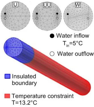
This study considers the dimensions of the energy piles characterising the foundation of the Swiss Tech Convention Centre. The energy piles are characterised by a height
and a diameter . In particular, thermal analyses are carried
out with respect to three different base-case models, where the foundation is characterised by single U, double U and W-shaped type configurations of pipes installed in the concrete (cf. Figure 4.1).
A preliminary approach: thermal behaviour of single energy piles Chapter 4 In order to avoid mesh sensitivity problems, extra-fine meshes of 49824, 66722 and 70970 elements are used to characterise the piles for the different foundations. Tetrahedral, prismatic, triangular, quadrilateral, linear and vertex elements are employed to describe the cylindrical 3-D finite element models. Tetrahedral elements are used near the joins of the pipes, while the remaining domain of the pile is covered with the swept method.
The pipes are simulated with a linear entity in which the fluid is supposed to flow. In all cases, the centres of the pipes are placed 126 mm from the boundary of the foundation. Fluid flow inside the pipes and the associated convective heat transfer is simulated by an equivalent solid, which has the same heat capacity (i.e., specific heat capacity and density) and thermal conductivity as the circulation fluid considered in reality. With this approach, which considers the thermal resistance due to the convective heat transfer between the water and the pipe inner wall as well as a conductive resistance in the pipe wall, the fluid domain can be used to inject a specific temperature inside the pipes.
4.1.2 Boundary conditions
The thermal boundary condition of the first kind is applied on the lateral and bottom surfaces of the pile, with a temperature constraint . The initial temperatures in the pipes and energy pile are imposed to , i.e., the average temperature recorder experimentally at the considered site during winter.
The thermal medium circulating inside the pipes (high-density polyethylene tubes) considered in the models is water. In the prosecution of the work the effects of the presence of glycol will be analysed.
The nominal velocity of fluid flow inside the pipes is , whereas their inner diameter is . The inflow temperature of the fluid is in all tests imposed to be
, referring to the operation of the energy foundation in winter conditions. The
shallower 4 meters of the pipes are thermally insulated in order to reproduce the interaction between the pile and the superstructure.
A preliminary approach: thermal behaviour of single energy piles Chapter 4
20
Figure 4.2: Finite element mesh used to simulate the real-scale problem.
4.1.3 Material properties
The energy pile and pipes properties, defined based on the literature review, are summarised in Table 4.1. Material [MPa] [-] [-] [kg/m3] [J/kgK] [W/mK] [1/K] [m/s] Concrete 28000 0.25 0.1 2500 837 1.628 1×10⁻⁵ - HDPE - - - 1100 1465 0.42 - -
Table 4.1: Material properties of energy pile and pipes (after [29]).
4.2 TEST RESULTS
The results of different numerical analyses considering the various pipes configurations inside a single energy pile are presented in the following. The tests, performed through 3-D transient finite element simulations, last 15 days in winter conditions, which are a good trade-off between computational effort and achievement of physically significant results.
4.2.1 Distribution of water temperature within the pipes
The thermal behaviour of a single energy pile equipped with single U, double U and W-shaped pipes is investigated herein.
The temperature trend of the water circulating in the pipes is reported in Figure 4.3. As it can be observed, water temperature increases along the flow direction with a linear trend. Increasing fluid outflow temperatures, Tout, are observed for the energy piles
A preliminary approach: thermal behaviour of single energy piles Chapter 4 very low time constant of the water is observed. Hence, the steady state conditions are reached within the first day of continuous functioning.
Figure 4.3: Distribution of water temperature within the pipes.
The 3-D results regarding the distribution of water temperature within the pipes after 15 days of test are reported in Figure 4.4.
A preliminary approach: thermal behaviour of single energy piles Chapter 4
22
4.2.2 Distribution of temperature within the concrete in proximity of the
tubes
Figure 4.5 shows the comparison between the distributions of temperature within the concrete for each type of layout, in proximity of the edges of the tubes. Due to the pile high heat capacity, it takes more than 1 day to approach to the steady-state conditions.
Figure 4.5: Distribution of temperature in proximity of the tubes.
Figure 4.6 shows the comparison between the temperature fields of the water within the pipes and of the concrete in proximity of the edges of the tubes, after 15 days of continuous functioning. As it can be observed, in the shallower 4 meters (circled in red in Figure 4.6) the temperature of the water is higher than the temperature of the concrete, causing a loss in the energy performance of the pile. This is due to the adiabaticity of this area of the pile which does not allow the concrete to exchange the heat.
A preliminary approach: thermal behaviour of single energy piles Chapter 4
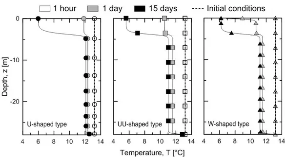
4.2.3 Axial distribution of temperature within the concrete
Figure 4.7 shows the comparison between the axial distributions of temperature for each type of layout.
As it can be noted, in the shallower 4 meters of the foundation the thermal insulation of the boundaries implies a strong cooling with respect to the initial conditions (i.e., ) during 15 days of continuous functioning.
After 15 days, the centre of the foundation equipped with single U, double U and W-shaped pipes layouts is subjected to an average cooling of and , respectively. The highest temperature variation is reached with the double U-shaped geometry of pipes because it involves the highest quantity of cold water in the heat exchange process.
The temperature distribution along the axial foundation depth does not remarkably varies in all cases between 7 and 15 days, respectively, indicating that the thermal conditions inside the pile are already close to the steady state after the first day of operation.
Figure 4.7: Axial distribution of temperature for different pipes technologies.
4.3 REMARKS
The results shown in this chapter are strongly influenced by both the presence of a boundary condition of the first kind close to the pipes and an adiabatic surface along the shallower 4 meters of the pile.
In order to simulate a model which is closer to the real case, different assumptions and boundary conditions are applied in the following.
Energy and geotechnical behaviour of
energy piles for different technological
approaches
Chapter
5
Energy and geotechnical behaviour of energy piles
for different technological approaches Chapter 5
The energy and geotechnical behaviour of such foundations, which is governed by their response to thermo-mechanical loads, is currently not fully understood especially considering different technological solutions for the heat exchange operation. Looking at such challenge, this part of the work summarises the results of numerical sensitivity analyses performed with respect to the real-scale energy foundation of the Swiss Tech Convention Centre at the Swiss Federal Institute of Technology in Lausanne (EPFL), aimed to investigate the thermo-mechanical response of a single energy pile for different pipes layouts, aspect ratios of the foundation, magnitudes of the fluid flow rate circulating in the pipes and fluid mixture compositions. The study outlines the impact that the different technological solutions have on the energy and geotechnical behaviour of energy piles as well as important forethoughts that engineers may consider for the design of such foundations.
5.1 FINITE ELEMENT MODELLING OF THE THREE
DIMENSIONAL CHARACTER OF ENERGY PILES
5.1.1 The experimental site
The dimensions of the energy pile and the characteristics of the surrounding soil deposit considered in this study are those of an experimental site located at the Swiss Federal Institute of Technology in Lausanne (EPFL) under the recently built Swiss Tech Convention Centre. The experimental site includes a group of four energy piles installed below a corner of a heavily reinforced raft supporting a water retention tank. The foundation of the tank includes, besides the four energy piles, eleven other conventional piles that are not equipped as heat exchangers. Specific information about the site can be found in Mimouni and Laloui [45].
This study considers only one of the four energy piles with respect to a configuration without any mechanical applied load on the top of the foundation, i.e., the one before the construction of the water tank. This choice is made for focusing on the impact of the solely thermal load on the mechanical behaviour of energy piles without considering the interaction of this action with any other form of upper restraint boundary loads (i.e., the constraint of the superstructure with the related body loads).
The energy pile is characterised by a height and a diameter
(cf. Figure 5.1). The pipes in the shallower first 4 m are thermally insulated to limit the affection of the heat exchange process by the variation of the atmospheric boundary conditions.
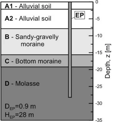
The characteristics of the soil deposit surrounding the piles (cf. Figure 5.1) are similar to those reported by Laloui, Nuth [4, 43], as the considered energy foundation is placed in a very close area to the one referred in these studies. The ground water table at the test site is at the top of the deposit.
Energy and geotechnical behaviour of energy piles
for different technological approaches Chapter 5
26
The upper soil profile consists of alluvial soil for 7.7 m depth. Below this upper layer a sandy gravelly moraine layer is present between 7.7-15.7 m depths. Then, a stiffer thin layer of bottom moraine is present between 15.7-19.2 m depths. Finally, a molasse layer is present below the bottom moraine layer.
Figure 5.1: Typical soil stratigraphy of the Swiss Tech Convention Center energy foundation.
5.1.2 Constitutive model
The reinforced concrete behaviour is reproduced by a thermo-elastic constitutive model. The same model is taken into account for reproducing the soil behaviour in view of the heating operation mode of the energy pile (i.e. superstructure heated, pile cooled), which is not considered a potential cause for triggering any plastic mechanisms in the soil region adjacent to the foundation.
This choice is supported also by a series of results of previous numerical simulations related to the same experimental site [46], which did not outlined any plastic mechanism for the soil (described by a thermoelasto-plastic constitutive model obeying the Mohr-Coulomb strength criterion), even considering a cooling operation mode for the energy pile (i.e., superstructure cooled, pile heated) that involved a strong heating of the foundation (i.e., pejorative condition).
5.1.3 3-D finite element model features
This study considers the dimensions of the energy piles characterising the foundation of the Swiss Tech Convention Centre. In particular, sensitivity analyses are carried out with respect to three different base-case models, where the foundation is characterised by single U, double U and W-shaped type configurations of pipes installed in the concrete.
Energy and geotechnical behaviour of energy piles
for different technological approaches Chapter 5
Extra-fine meshes of 107087, 88597 and 98357 elements are used to characterise the models for the different foundations. Tetrahedral, prismatic, triangular, quadrilateral, linear and vertex elements are employed to describe the 3-D finite element models.
Figure 5.2 reports the features of a typical model exploited for the study, with a focus on the mesh used to characterise the pile with different pipes configurations. The energy pile is described by 49824, 66722 and 70970 elements for the single U, double U and W-shaped type configurations, respectively. The soil surrounding the pile is then characterised by the remaining 57263, 21875 and 27387 elements for the various models. Tetrahedral elements are used near the joins of the pipes, while the remaining domain of the pile is covered with the swept method. The pipes are simulated with a linear entity in which the fluid is supposed to flow. In all cases, the centres of the pipes are placed 126 mm from the boundary of the foundation. With this approach, which considers the thermal resistance due to the convective heat transfer between the water and the pipe inner wall as well as a conductive resistance in the pipe wall, the fluid domain can be used to inject a specific temperature inside the pipes.
The following analyses, performed to investigate the response of the energy pile in the considered saturated soil deposit under mechanical and thermal actions, consider the thermal, mechanical and hydraulic characteristics of the problem through a thermo-hydro-mechanical mathematical formulation. The analysis of these three aspects, which are strictly coupled, is carried out through equations (1-8).
5.1.4 Boundary conditions
Restrictions are applied to both vertical and horizontal displacements on the base of the mesh (i.e., pinned boundary) and to horizontal displacements on the sides (i.e., roller boundary).
The initial stress state due to gravity in the pile and the soil is considered as geostatic and calculated assuming a coefficient of earth pressure at rest .
The thermal boundary condition on the vertical sides of the mesh and the bottom of the mesh is a first kind condition (i.e., uniform and constant temperature ).
The initial temperatures in the pipes, energy pile and soil are imposed to , i.e., the average temperature recorder experimentally at the considered site during winter. The thermal medium circulating inside the pipes (high-density polyethylene tubes) considered in the base-case models is water. The nominal velocity of fluid flow inside the pipes is , whereas their inner diameter is . The inflow temperature of the fluid is in all tests imposed to be , referring to the operation of the energy foundation in winter conditions. To simulate the shallower 4 meters of the pipes that are thermally insulated, the term in (2) is considered null.
Energy and geotechnical behaviour of energy piles
for different technological approaches Chapter 5
28
The hydraulic boundary conditions result from assuming the pile as impervious, allowing the drainage of the soil layer to take place through the vertical and bottom sides of the model. The initial pore water pressure distribution corresponds to the hydrostatic profile with a water table located at the top surface. Throughout the tests, pore water pressure is allowed to vary as a consequence of the thermo-mechanical actions involved in the problem.
Figure 5.2: Boundary conditions and finite element mesh used to simulate the real-scale problem.
5.1.5 Material properties
The soil deposit, energy pile and pipes properties are defined based on the literature review and in view of technical documentations related to the considered engineering project [4, 29, 45, 46, 48, 49]. They are summarised in Table 5.1.
Soil layer [MPa] [-] [-] [kg/m3] [J/kgK] [W/mK] [1/K] [m/s] A1 190 0.22 0.1 2769 880 1.8 1×10⁻⁵ 7×10⁻⁶ A2 190 0.22 0.1 2769 880 1.8 1×10⁻⁵ 1×10⁻⁵ B 84 0.4 0.35 2735 890 1.8 1×10⁻⁵ 1×10⁻⁵ C 90 0.4 0.3 2740 890 1.8 1×10⁻⁵ 2×10⁻¹⁰ D 3000 0.2 0.1 2167 923 1.11 1×10⁻⁵ 2×10⁻¹⁰
Energy pile and pipes
Concrete 28000 0.25 0.1 2500 837 1.628 1×10⁻⁵ -
HDPE - - - 1100 1465 0.42 - -
Energy and geotechnical behaviour of energy piles
for different technological approaches Chapter 5
5.2 THERMO-MECHANICAL SENSITIVITY OF ENERGY
PILES TO DIFFERENT TECHNOLOGIES
The results of different numerical sensitivity analyses considering various pipes configurations inside a single energy pile, foundation aspect ratios, magnitudes of fluid flow rate inside the pipes and fluid compositions are presented in the following. The tests, performed through 3-D transient finite element simulations, last 15 days in winter conditions. Compressive stresses and strains are considered positive, as are downward displacements (i.e., settlements).
5.2.1 Influence of pipes layout
The thermo-mechanical behaviour of a single energy pile equipped with single U, double U and W-shaped pipes is investigated herein.
Figure 5.3 shows the comparison between the axial distributions of temperature for each type of layout. As it can be noted, any remarkable temperature variation characterises the shallower 4 meters of the foundation, because the pipes in this region are thermally insulated. After 15 days, the centre of the foundation equipped with single U, double U and W-shaped pipes layouts is subjected to an average cooling of and , respectively. The highest temperature variation is reached with the double U-shaped geometry of pipes because it involves the highest quantity of cold water in the heat exchange process.
A more pronounced cooling of the bottom part of the pile is observed because of the lower thermal conductivity of the molasse layer, which inducing a lower heat exchange with the foundation makes the effect of the conductive heat transfer with the inner pipes containing cold water predominant.
The temperature distribution along the axial foundation depth does not remarkably varies in all cases between 7 and 15 days, respectively, indicating that the thermal conditions inside the pile are already close to the steady state during the first week of operation. The axial distributions of stress induced by the temperature variations described above are shown in Figure 5.4 (the initial stress distribution due to the foundation body load is subtracted). Maximum values of stress -800, -1400 and -1300 kPa are observed along the axial depth of the foundation for single U, double U and W-shaped pipes layouts, respectively.
The magnitude of these results is coherent with the previously observed data, as the pipes configurations that lead the greater negative temperature variations inside the pile are those for which the greatest stresses resulting from the foundation thermal contraction are observed.
Energy and geotechnical behaviour of energy piles
for different technological approaches Chapter 5
30
Figure 5.3: Axial distribution of temperature for different pipes technologies.
Figure 5.4: Axial distribution of thermal vertical stress for different pipes technologies.
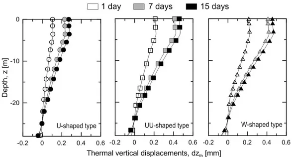
Figure 5.5 shows the axial distribution of vertical displacements for each technology. Coherently with the distributions of temperature and stress, the greatest effect in terms of displacements of the cold flow within the tubes is observed for the pile with the double U-shaped pipe layout, while the smallest effect is observed in the foundation with the single U-shaped type. Maximum pile settlements and are observed for the energy pile equipped with single U, double U and W-shaped pipes layouts, respectively.
The null point, which represents the plane where any thermally induced displacement occurs in the foundation [49], is close to the bottom of the energy pile in all cases as a consequence of the end-bearing behaviour of the foundation.
Energy and geotechnical behaviour of energy piles
for different technological approaches Chapter 5
Figure 5.5: Axial distribution of thermal vertical displacements for different pipes technologies.
The temperature trend of the water circulating in the pipes is then reported in Figure 5.6. As it can be observed, water temperature increases along the flow direction with a linear trend. However, the slight changes of the slope of the curves indicate that the increase is not uniform. The reason is that the spatial progressive rising of water temperature in the pipe reduces the heat transfer potential with the soil, thus leading to slower further temperature increases.
Increasing fluid outflow temperatures, Tout, are finally observed for the energy piles
characterised by double U, single U and W-shaped pipes configurations, respectively.
Energy and geotechnical behaviour of energy piles
for different technological approaches Chapter 5
32
The trend of energy extraction for the energy pile equipped with the different considered pipes layouts throughout the entire duration of the tests is reported in Figure 5.7. Complementary data referred to the end of the analyses are finally considered in Table 5.2.
A decrease of the rate of energy extraction (i.e., rate of heat exchanged between the fluid circulating in the pipes and the surrounding system) along the foundation depth, ̇ , is observed throughout the tests (cf. Figure 5.7).
Any significant difference in this trend is remarked between the piles equipped with double U and W-shaped pipes configurations, even if in the former case a double volumetric flow rate, ̇, than the one considered as reference for the study (i.e., ̇ ) is exploited.
Therefore, it is considered the W-shaped pipe layout as the most efficient technological solution between those analysed in this study. Then, the higher rate of energy extraction is obtained through the double U and W-shaped pipes technologies, respectively, whereas lower amounts of energy can be extracted through the single U-shaped pipe technology. This result can also be observed in Table 5.2, which shows for the energy pile equipped with double U-shaped pipes a 36% larger rate of energy extraction than the one obtained through a single U-shaped pipe technology, whereas a 2% greater extraction than the one achieved through the W-shaped pipe technology. Furthermore, Table 5.3 shows the trend of the effectiveness of heat transfer at different times of the 15 days long simulation (with ̇ ̇ ).
Energy and geotechnical behaviour of energy piles
for different technological approaches Chapter 5
Technology Tout [°C] ΔT [°C] ̇ [l/min] ̇ [W/m]
Single U-shaped 5.70 0.70 10 17.43
Double U-shaped 5.55 0.55 20 27.43
W-shaped 6.08 1.08 10 26.86
Table 5.2: Energy performance of energy piles for different pipes configurations.
̇ ̇ [%] Single U Double U W 1 day 12.4% 11.9% 23.4% 7 days 9.1% 7.3% 14% 15 days 8.5% 6.7% 13.2%
Table 5.3: Trend of effectiveness for different pipes configurations.
The behaviour shown above is also validated by the results reported in the following. Figure 5.8 shows the distributions of temperature of the water flowing within the pipes and of the concrete in proximity of the edge of the pipes after 1, 7 and 15 days of continuous functioning.
A decrease of the average temperature difference between concrete and water is observed and this involves a consequent decay of heat transfer efficiency with time.
Figure 5.8: Distribution of temperature of the water within the pipes and of the concrete in proximity of the edge of the pipes.
Energy and geotechnical behaviour of energy piles
for different technological approaches Chapter 5
34
5.2.2 Influence of the foundation aspect ratio
The thermo-mechanical behaviour of a single energy pile with aspect ratios
and is investigated in the following. The analyses
are performed with respect to the different pipes layouts previously considered and the results compared in each case to those for the energy pile characterised by the nominal aspect ratio .
Figure 5.9 shows the comparison between the axial distributions of temperature for each type of considered aspect ratio in view of different pipes configurations. The foundation depth is considered in a-dimensional form with respect to the total height of the pile, HEP.
Different temperature distributions along the foundation depth are observed for the various considered aspect ratios depending on the thermal storage capacities of the various soil layers. As previously observed, the highest temperature variations (and therefore the highest axial stresses, strains and displacements variations) characterise the energy pile equipped with double U-shaped pipes.
The axial distributions of stress in the pile induced by the temperature change are then shown in Figure 5.10. Lower and more homogeneous distributions of vertical axial stress are observed for the piles of lower aspect ratios and , whereas higher and less homogeneous distributions are remarked for the foundation characterised by nominal dimensions ( ) and the one with the highest aspect ratio .
This result is induced by (i) the different bearing behaviour characterising the foundation in the various considered cases, i.e., frictional (floating pile) until almost 20 m depth are reached and end-bearing (end-bearing pile) from 20 m depth on, as well as by (ii) the impact of the thermal properties of the various soil layers in the heat exchange process, which involve lower cooling and related thermally induced stress for the shallower piles (heat exchange occurs more rapidly), whereas higher cooling and related stress in the bottom part of the deeper piles (heat exchange occurs more slowly).
Upper bound values of axial stress -926, -1531 and -1513 kPa are reached in the bottom half of the deeper and more constrained foundation for single U, double U and W-shaped pipes layouts, respectively. Lower bound values of axial stress -181, -300
and -261 kPa are reached close to the centre of the shallower and less constrained foundation for the same pipes configurations.
Energy and geotechnical behaviour of energy piles
for different technological approaches Chapter 5
Figure 5.9: Axial distribution of temperature for different piles aspect ratios.
Figure 5.10: Axial distribution of thermal vertical stress for different piles aspect ratios.
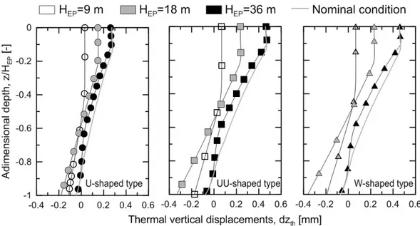
The effect of the different foundation constraints and thermal properties of the various soil layers can also be observed in Figure 5.11, which shows the thermal vertical displacements along the a-dimensional foundation depth for different pipes technologies. The null point location is close to the geometrical centre of the foundation for aspect ratios 9 and 18, whereas close to the bottom for aspect ratios 31 and 36, respectively. This result outlines the end-bearing behaviour of the foundation for depths almost greater than 20 m, where the molasse layer starts and involves the transfer of the highest fraction of load to the pile toe. Upper bound values of settlements 0.3, 0.7 and 0.65 mm are observed for the deeper foundation, for single U, double U and W-shaped pipes layouts, respectively. Lower bound values of settlements 0.27, 0.47
Energy and geotechnical behaviour of energy piles
for different technological approaches Chapter 5
36
and 0.47 mm are observed for the deeper foundation, equipped with the same pipes configurations.
Figure 5.11: Axial distribution of thermal vertical stress for different piles aspect ratios.
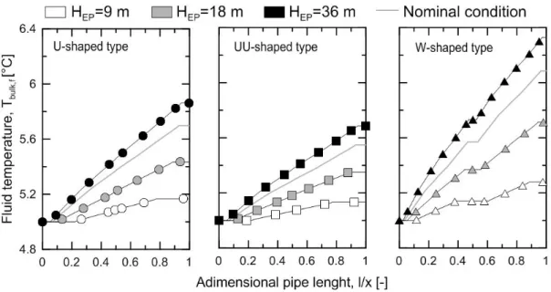
The distribution of water temperature inside the pipes throughout the entire duration of the tests and useful data related to the piles energy performance at the end of the analyses are finally summarised in Figure 5.12 and Table 5.4, respectively. The pipe length is expressed in a-dimensional form with respect to its total dimension, x. As it can be observed from Figure 5.12, the temperature of the operative fluid in the pipes increases more for increasing aspect ratios of the pile.
Coherently with the results previously observed through the analyses that considered different pipes configurations, absolute energy output of the energy pile with double U-shaped pipes is the largest among all the solutions analysed in this study, followed, in order, by the foundation equipped with W and single U-shaped pipes (cf. Table 5.4). A doubling of the foundation aspect ratio from 10 to 20 involves an increase of the energy output up to 170%, while a doubling from 20 to 40 brings an increase of the energy output up to 100%, depending on the type of pipe layout.
Energy and geotechnical behaviour of energy piles
for different technological approaches Chapter 5
Figure 5.12: Distribution of water temperature within the pipes for different piles aspect ratios.
Single U-shaped pipe
AR [-] Tout [°C] ΔT [°C] ̇ [l/min] ̇ [W/m] NTU ̇ ̇ [%]
10 5.17 0.17 10 13.18 0.7 2.1%
20 5.43 0.43 10 16.67 1.4 5.2%
40 5.86 0.86 10 16.67 2.8 10.5%
Double U-shaped pipes
10 5.13 0.13 20 20.15 0.7 1.6% 20 5.35 0.35 20 27.13 1.4 4.3% 40 5.69 0.69 20 26.74 2.8 8.4% W-shaped pipe 10 5.28 0.28 10 21.70 1.41 3.4% 20 5.71 0.71 10 27.52 2.82 8.7% 40 6.33 1.33 10 25.77 5.64 16.2%
Table 5.4: Energy performance of energy piles for different aspect ratios.
5.2.3 Influence of the magnitude of the fluid flow rate circulating in the
pipes
The thermo-mechanical behaviour of a single energy pile characterised by different magnitudes of fluid flow rates circulating in the pipes is investigated herein. Because the fluid flow rate can change both for a variation of the tube diameter, , (i.e., cross section of the tube) and fluid velocity, , the following numerical analyses consider the aforementioned options through two different series of tests.
First the response of the energy pile equipped with pipes with different diameters, filled by water at constant velocity, is considered. Finally, the response of the energy pile equipped with tubes of the same diameter, but characterised by different velocities of the circulating fluid, is investigated.
Energy and geotechnical behaviour of energy piles
for different technological approaches Chapter 5
38
The analyses are performed with respect to the different pipes layouts previously analysed and the results compared in each case to those for the energy pile characterised by the nominal features.
5.2.3.1 Pipes diameter variation
Results concerning the axial distribution of temperature obtained for varying pipes diameters ( and ) with respect to the nominal conditions ( ) and for different pipes layouts are shown in Figure 5.13.
The most remarkable differences between the temperature distributions are observed only along the axial depth of the energy pile characterised by W-shaped pipes, in which an increase of the pipe diameter by compared to the nominal condition involves a further cooling of the pile of °C.
Figure 5.13: Axial distribution of temperature for different pipe diameters.
The uniform temperature distributions along the foundation depth lead to small variations of the axial stress distributions for different pipes diameters and layouts.
The more pronounced variations are noted for the energy pile equipped with W-shaped pipes, where the use of tubes with diameter involves an increase of about -400 kPa of axial vertical stress with respect to the main trend of the curves. The magnitudes of the maxima and minima values of axial vertical stress in the foundation are in the range observed thus far.
Energy and geotechnical behaviour of energy piles
for different technological approaches Chapter 5
Figure 5.14: Axial distribution of vertical stress for different pipe diameters.
The distribution of water temperature inside the pipes and the trend of energy extraction for the energy pile equipped with pipes with different diameters throughout the entire duration of the tests are reported in Figure 5.15. Complementary data referred to the end of the analyses are considered in Table 5.5.
Figure 5.15 shows an increase in outflow temperature when reducing the diameter of the pipe, since the flow rate decreases. The most important effect related to a variation of the pipes diameter is observed in energy piles with W-shaped pipes. The energy analysis reports that, besides the decay of the heat transfer rate with time, up to 10% of energy output is gained if the diameter of the pipes is brought from 25 to 40 mm (c.f. Table 5.5). The variations of the energy performance have to be evaluated in relation to the variations of the pressure losses for length unit of the pipe (+28% and -20% for and , respectively, compared to the nominal condition) with implications on the electrical power absorbed by the circulation pump.
Energy and geotechnical behaviour of energy piles
for different technological approaches Chapter 5
40
Figure 5.15: Distribution of water temperature within the pipes for different pipe diameters and relative trend of rate of energy extraction from the soil.
Single U-shaped pipe
[mm] Tout [°C] ΔT [°C] ̇ [l/min] ̇ [W/m] ̇ ̇ [%]
25 6.07 1.07 6 16.00 13%
40 5.46 0.46 15 17.18 5.6%
Double U-shaped pipes
25 5.85 0.85 12 25.43 10.4%
40 5.36 0.36 30 27 4.4%
W-shaped pipe
25 6.64 1.64 6 24.54 20%
40 5.72 0.72 15 26.89 8.8%
Table 5.5: Energy performance for different pipes diameters.
5.2.3.2 Fluid velocity variation
Results concerning the axial distribution of temperature obtained varying the water velocities within the pipes ( and ) with respect to the nominal condition ( ) and for different pipes layouts are shown in Figure 5.16.
The most remarkable differences between the temperature distributions are observed only along the axial depth of the energy pile equipped with W-shaped pipes, in which an increase of the fluid velocity from to compared to the nominal condition involves a further cooling of the foundation of .
Energy and geotechnical behaviour of energy piles
for different technological approaches Chapter 5
Figure 5.16: Axial distribution of temperature for different water velocities.
The effects of the uniform temperature distributions along the foundation depth for the pile characterised by single U and double U-shaped pipes, respectively, can also be observed in Figure 5.17, where any remarkable variations of the axial stress distributions are noted.
The more pronounced variation with respect to the response of the foundation with nominal features is perceived when dealing with piles equipped with W-shaped pipes, where a greater fluid velocity 0.5 or 1 m/s involves an increase of about -400 kPa of axial vertical stress. The magnitudes of the maxima and minima values of axial vertical stress in the foundation are in the range observed thus far.
Figure 5.17: Axial distribution of thermal vertical stress for different water velocities.
The distribution of water temperature inside the pipes and the trend of energy extraction for the energy pile equipped with pipes with different fluid velocities throughout the
Energy and geotechnical behaviour of energy piles
for different technological approaches Chapter 5
42
entire duration of the tests are reported in Figure 5.18. Complementary data referred to the end of the analyses are considered in Table 5.6.
Figure 5.18 shows a decrease of water temperature within the pipes for an increase of the water velocity because the flow rate increases and the heat exchange occurring between the operative fluid and the surrounding system is faster (i.e., less pronounced). However, despite the typical decay of heat transfer efficiency, a sensible growth of heat flow is observed for a variation of the fluid velocity (cf. Table 5.6). In fact, a variation of the water velocity within the pipes from to involves an increase up to 7% in the energy output, whereas the variation from to implies an increase up to 11%. These variations depend on the type of pipe layout.
The variations of the energy performance have to be evaluated in relation to an increase of the pressure losses for length unit of the pipe (525% and 2400% for and , respectively, in respect to the nominal condition) with implications on the electrical power absorbed by the circulation pump.
Figure 5.18: Distribution of water temperature within the pipes for different water velocities and relative trend of rate of energy extraction from the soil.
Energy and geotechnical behaviour of energy piles
for different technological approaches Chapter 5
Single U-shaped pipe
[m/s] Tout [°C] ΔT [°C] ̇ [l/min] ̇ [W/m] ̇ ̇ [%]
0.5 5.29 0.29 25 18.07 3.7%
1 5.15 0.15 50 18.68 1.9%
Double U-shaped pipes
0.5 5.23 0.23 50 28.64 2.9%
1 5.12 0.12 100 29.89 1.5%
W-shaped pipe
0.5 5.46 0.46 25 28.64 5.8%
1 5.24 0.24 50 29.89 3%
Table 5.6: Energy performance for different water velocities circulating inside the pipes.
5.2.4 Influence of fluid composition circulating in the pipes
Antifreeze is a chemical additive which lowers the freezing point of a water-based liquid. Within the pipes it is often useful to insert an antifreeze liquid mixed with water to avoid technical problems, especially when dealing with foundation working conditions characterised by very low temperature regimes.
Ethylene glycol (MEG, molecular formula: ) is an organic compound primarily used as a raw material in the industry. It is also used in industrial applications like antifreeze. It is an odourless, colourless, syrupy, sweet-tasting liquid. Ethylene glycol is only weakly toxic, but cases of poisonings are not uncommon. Very small amounts of ingested antifreeze (an ounce or less) can be fatal.
In geothermal heating/cooling systems, ethylene glycol (pure or in mixtures) is the fluid that transports heat through the use of a geothermal heat pump. The ethylene glycol either gains energy from the source or dissipates heat to the source, depending if the system is being used for heating or cooling.
The behaviour of a single energy pile containing antifreeze additives MEG 25 and MEG 50 (mixtures with 25% and 50% of mono-ethylene glycol in water, respectively) in the pipes is investigated in the following. The analyses are performed with respect to the different pipes layouts previously considered and the results compared in each case to those for the energy pile equipped with pipes with circulating water, i.e., the nominal condition.
Energy and geotechnical behaviour of energy piles
for different technological approaches Chapter 5
44 MEG 25 [°C] [kg/m3] [J/kgK] [W/m K] [Pa·s] -10 1048 3713 0.477 3.186×10⁻³ -5 1046 3719 0.481 2.704×10⁻³ 0 1045 3726 0.485 2.314×10⁻³ 5 1044 3734 0.489 1.995×10⁻³ 10 1042 3742 0.493 1.733×10⁻³ MEG 50 -10 1094 3201 0.413 5.316×10⁻³ -5 1092 3221 0.412 4.428×10⁻³ 0 1090 3240 0.411 3.723×10⁻³ 5 1087 3260 0.410 3.157×10⁻³ 10 1084 3280 0.408 2.7×10⁻³
Table 5.7: Thermal properties of MEG 25 and MEG 50.
Figure 5.19 shows the comparison between the axial distributions of temperature obtained along the foundation depth resulting from the use of different types of heat carrier fluids.
Figure 5.19: Axial distribution of temperature for different types of operative fluids.
Any sensible differences in the axial distributions of temperature within the pile are observed for the various configurations considered. Therefore, the mechanical response of the foundation is not expected to markedly vary both in terms of stress and displacements development.
The distribution of water temperature inside the pipes and the trend of the energy extraction for the energy pile equipped with pipes with different operative fluids throughout the entire duration of the tests are reported in Figure 5.20. Complementary data referred to the end of the analyses are considered in Table 5.8.
Energy and geotechnical behaviour of energy piles
for different technological approaches Chapter 5
Figure 5.20 shows the distribution of water temperature along the pipe length as well as the trend of rate of heat transfer for the different considered fluids and pipes layouts. The use of antifreeze liquids does not sensibly affect the temperature of the fluid within the pipes, but can induce variations of the system energy performance because of the lower specific heat capacity of the medium. Table 5.8 shows that a 25% concentration of MEG in water involves a decrease up to 6% in the rate of energy output compared to the nominal condition with pure water, whereas a 50% concentration of MEG involves a decrease up to 12% with respect to the same base-case.
Figure 5.20: Distribution of operative fluid temperature within the pipes and relative trend of rate of energy extraction from the soil.
Single U-shaped pipe
Type of antifreeze
Tout [°C] ΔT [°C] ̇ [l/min] ̇ [W/m] ̇ ̇ [%]
MEG 25 5.74 0.74 10 16.43 9%
MEG 50 5.8 0.8 10 15.54 9.7%
Double U-shaped pipes
MEG 25 5.59 0.59 20 26.21 7.2%
MEG 50 5.64 0.64 20 24.82 7.8%
W-shaped pipe
MEG 25 6.19 1.19 10 26.46 14.5%
MEG 50 6.23 1.23 10 23.86 14.9%