1
1 INDEX
2 Introduction (ISO11783 – ISOBUS and AEF PT10) ...4
3 The choice for a new physical layer ...7
3.1 CAN Flexible Data rate ...8
3.2 Flexray ...9
3.3 IEEE 802.3 – Ethernet ... 10
3.3.1 IEEE 802.3 100-baseTX ... 11
3.3.2 O.P.E.N. Alliance Broadr-Reach ... 12
4 The TCP/IP stack ... 15
4.1 IP ... 15
4.2 ICMP ... 19
4.3 IEEE 802.1q (VLAN) ... 20
5 Industrial Ethernet Fieldbuses and AVB ... 22
5.1 Criteria ... 22 5.1.1 Technical aspects ... 22 5.1.2 Performance ... 23 5.1.3 Implementation Costs... 23 5.2 AVB ... 23 5.2.1 Introduction ... 23 5.2.2 Technical aspects ... 30 5.2.3 Performance ... 32 5.2.4 Implementation Costs... 32 5.3 EtherCAT ... 33 5.3.1 Introduction ... 33 5.3.2 Technical aspects ... 34
2 5.3.3 Performance ... 36 5.3.4 Implementation Costs... 37 5.4 Powerlink ... 38 5.4.1 Introduction ... 38 5.4.2 Technical aspects ... 40 5.4.3 Performance ... 41 5.4.4 Implementation Costs... 42 5.5 TTEthernet ... 43 5.5.1 Introduction ... 43 5.5.2 Technical aspects ... 45 5.5.3 Performance ... 47 5.5.4 Implementation Costs... 48 5.5.5 Comparison ... 48 6 Research Methodology ... 49 7 Prioritization ... 52
7.1.1 Test system setup ... 52
7.2 L2 prioritization: VLANs and IEEE802.1p ... 54
7.2.1 L2 prioritization configuration ... 55
7.2.2 L2 prioritization tests and results ... 55
7.3 L3 ... 58
7.3.1 L3 prioritization configuration ... 59
7.3.2 L3 prioritization test and results ... 61
8 Adopting Powerlink ... 67
3
8.1.1 Video streaming over 2 “safety” cameras (on the rear left and rear right corner) to a
graphical terminal ... 69
8.1.2 Sophisticated visualization on one graphical terminal, from connected to implement ECUs 69 8.1.3 Improved service and diagnosis (flash ECUs, log files, raw data streams) ... 70
8.2 Architectural hierarchy, comparison ... 71
8.2.1 One MN, on-demand multicast communications ... 72
8.2.2 Application-specific MNs ... 72
8.3 Hotpluggability and runtime configurations ... 73
9 Conclusions ... 76 10 Abbreviations ... 78 11 Ringraziamenti ... 78 12 Bibliography ... 79 13 Pubblications on Conferences ... 83 14 Pubblications on Journals ... 84
4
2 Introduction (ISO11783 – ISOBUS and AEF PT10)
This work is the result of the research conducted at the IMAMOTER-CNR, Institute for Agricultural and Earth-Moving Machinery. IMAMOTER is a research centre whose research has focused on different aspects of agricultural machinery, construction equipment and, in general, heavy-duty vehicles. The research staff of the Institute is formed by groups of engineers with diverse specialization and is a national and European excellence for the part of the hydraulic and electronic control of the hydraulic components, namely mechatronics related to electrohydraulic applications.
As a historical note, IMAMOTER was born as an institution dedicated to the mechanics, following the technologies related to agricultural and earth-moving machinery. The electronic technology was introduced in the last fifteen years, and over time has found its space and has gained an increasingly important role in reducing the dependency of applications from single mechanical part and, at the same time, helping to improve the precision of the control systems designed. The advance of the electronics, with the possibility of using higher computing powers, has paved the way to computer technology and automatic controls, namely the possibility of using programmable logic in order to obtain even more advanced controls and valid for different applications. With the advance of the technology and communication, protocols has opened the perspective of being able to integrate systems, originally designed as a stand-alone, in distributed control systems, with multiple electronic control units (ECU), each performing a specific function, increasing the scalability and reusability of each component.
In recent years, the adoption of network protocols in wired and wireless networks with high throughput in the aforementioned scenarios have enabled ECU systems or machines to work in a collaborative or cooperative manner (the so-called clusters) bringing automation and automation of machining on the field at unimaginable levels only a few years ago. Increased automation of processes and the increasing complexity of systems has ultimately led to a careful evaluation of the functional safety components that such systems can offer.
With the publication of SAE J1939, which standardizes communications between ECU in heavy-duty machines, specifically powertrain networks, multi-vendor ECUs could communicate with each other over the same machine. One specialized evolution of this standard, established in 2002, is ISO 11783, which is based on the same architecture of the standard SAE J1939 (up to the ISO OSI’s layer 4). The aim of standardizing all agricultural applications, creating a de facto standard for treatments and precision automations (precision farming) and fleet management led to the creation of ISO 11783 (a.k.a. ISOBUS). Unlike J1939, where each ECU occupies a well-defined functionality within the machine, decided by the
5
machine manufacturer (system integrator), a major feature of ISO 11783 is the ability to hotplug, which supports interconnection ECUs on-the-fly, which auto-configure themselves in order to perform the functions in the network. Both SAE J1939 and ISO 11783 use the CAN (Controller Area Network) bus as their fieldbus, which was specified by Bosch Automotive in 1992 with the CAN specification 2.0 A and 2.0 B, then transposed to the ISO standard ISO 11898.
As functionalities of precision farming had increased both in number and maturity, so had the amount of data exchanged for the same operation of the system. However, the introduction of new features, (e.g. the autonomous driving) and the increasing number of ECU within a network of a modern tractor saturated the offered bandwidth on the network, reaching the limit of the CAN bus.
Many automotive vendors saw in Ethernet (and its field busses, as explained later) a complementary bus, side by side to other traditional buses like CAN, LIN and Flexray, which would allow high-speed communication to take place, thus enabling the development of innovative applications which need to exchange high amount of data.. This trend follows the one involving the automotive industry, for which is foreseen an exponential growth.
To fulfill industrial and specific needs of determinism and safety, many products modifying the standard Ethernet were designed, altering its characteristics. Those products can be roughly ranked as follow:
the access method - whereas standard Ethernet is designed to be random access, many successful fieldbuses provide a time-triggered access method;
the hierarchy of the network - creating a Master/Slave paradigm, in spite of the usual plain hierarchy (though at application layer various hierarchical models still can be applied, such as Client/Server or Peer-to-Peer).
Examples of the most successful fieldbuses are EtherCAT, Ethernet/IP, Powerlink, Profinet and SERCOS III.
It is beyond the scope of the thesis, to make a comparison between these products, as many of these can be found in literature [1, 2, 3, 4] and respond to a variety of different needs; instead, the research deals with the feasible infrastructures and technologies to be adopted in AG Mobile environments. The focus will be put on cost effectiveness and performances in a standard Ethernet network infrastructure, leveraging well-established and standardized technologies, customizing them for industrial compartments, such as automotive and heavy-duty machines ones, which normally cannot count on such a variety of technological
6
diversity. Industrial automation solutions, referred as fieldbus, also provide interesting approaches that will be evaluated.
Another important advantage is the availability of hardware: even in consumer compartment, a broad support, both commercial and open source, and the easiness of use, which would speed up development and reduce time-to-market of products that can rely on this technology for distributed control. Furthermore, where Ethernet 100base-TX physical layer lacked (e.g. environmental robustness to EMC, cable length, etc.) silicon industries (e.g. Broadcom PHYs) provided with many interesting products that are definitively allowing Ethernet to enter this delicate yet advantageous industry compartment.
The choice of adopting standard Ethernet and TCP/IP stack, for these early tests has been encouraged by the fact that other players in different markets (particularly avionics and ) are using the Internet Protocol Suite.
The research focused on the possible ways to prioritize the traffic, in a congested network, in order to achieve a certain level of determinism and prioritize the traffic in order to prevent data losses. The target is to achieve real high dynamics distributed control, such as “x-by-wire”. This thesis will try to approach this problem in an architectural and technological way.
The candidate has been nominated expert by CUNA (Technical Committee of Unification in Automotive) to participate at standardization meetings of ISO11783, where he proposed and led a Preliminary Task Force for the investigation of a new “high bandwidth for two years. the work converged in the AEF PT10 “High Speed ISOBUS” working group, to which the candidate attends regularly and actively participates. The Agricultural Industry Electronics Foundation (AEF) assists AEM (Association of Equipment Manufacturers) members as they develop the hardware and electronic communication protocols to allow and confirm reliable communications between several related machines or implements, even though they are made by different manufacturers. The overall objective of AEF is to develop harmonized technology enabling equipment, components and software manufactured anywhere and by anyone to operate seamlessly together.
7
3 The choice for a new physical layer
Automotive industry is accustomed to CAN bus topology, featuring relatively low cost per meter but high lengths resulting in heavy weight and considerable costs burden for wiring and consumes, without mentioning the low throughput of CAN. On the other hand, Flexray bus enjoys a star topology, which reduces wirings length sensibly, but due to the costs of controllers, wirings and stiffness of the network dynamics, this standard does not seem to be eligible to become the next de facto standard for in-vehicle distributed control. The advantages of having a star topology using Ethernet are multiple:
Cost effectiveness in terms of wiring costs and weight;
Easiness in topology changes and transparency for traffic bound outside the vehicle;
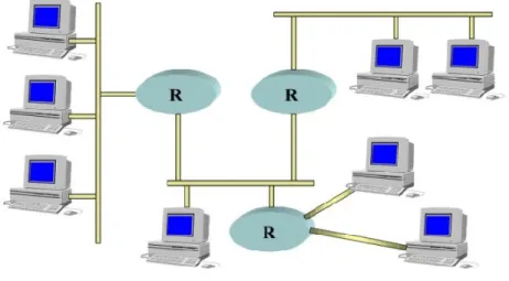
The possibility to use Ethernet as a backbone to interconnect systems rather than single ECUs (cfr Figure 1), which may still communicate, inside their own system with other convenient buses, as feasibility to make gateways to translate traffic between heterogeneous busses has been already proven before [5].
Figure 1: Hypothetical heterogeneous topology for heavy-duty vehicles
With the openings of the AEF PT10 working group, the main objective was to scout with functionalities and relative requirements needed for a new “high-speed” network. Nevertheless, initially it seemed appropriate to rank the currently available busses, to evaluate the feasibility of a certain network in the various application scenarios. The results have been published and resumed in this table. In the table, Wi-Fi also appeared for M2M communication, which is out of the scope for this work, thus will not be discussed, as well as Ethernet AVB and industrial Ethernet fieldbuses, which will be discussed later.
8 Openness Hardware availability/c ost Bandwidth Hotplug Capabilit y Topolo gy Safety Ag Mobile Compliancy (EMI/EMC, environmen tal robustness, …) IEEE 8 0 2. 3 YES High availability, both COTS and industrial solutions 100/1000M bit
YES Every NO (possible w/openSAFE TY) PHY dependent IEEE 8 0 2 .3 AVB YES Low availability, expensive network infrastructur es 100/1000M bit
YES Every NA PHY
dependent
Eth Fieldb
u
ss
e
s mostly YES Some have custom PHY and MACs 100/1000M bit (not every fieldbus is Gigabit ready) depend s on the field bus
Every Many have IEC-61508 SIL 3 certified layer PHY dependent C A N -FD under ISO standardizati on ISO11898-2/6 transceivers 2Mbit for ISOBUS theoretical YES Physica l bus NA NA Flex ra y under ISO standardizati on Expensive controllers up to 10Mbit NO (attemp ts were made to enable feature) Star NO YES IEEE 8 0 2 .1 1 b /g /n /p open standard high availability, COTS solutions up to 300 Mbit YES star or mesh NO (maybe w/openSAFE TY) NO (p?)
Table 1: comparison between various communication network
3.1 CAN Flexible Data rate
Considered as the successor to the CAN 2.0 [7], namely CAN Flexible Data Rate (CAN-FD) was developed within Bosch and published in 2011. Defined as with standard ISO 11898 and capable of
9
supporting higher throughput using data packets up to 64 bytes contained in the same space of the old 8-byte packets.
The bitrate is dynamic, while the phase of arbitration and acknowledge remains identical to the protocol CAN 2.0, the bitrate of data field can be increased up to 8 times the standard one. Therefore, in the space of 8 bytes + checksum can send packets of 16, 32 or 64 bytes, with a 17 or 21-bit checksum. The main disadvantage is that, despite being defined as compatible, nodes equipped with the device CAN classic do not recognize the data and fail checksum calculation, thus filling the network with Error Frame. Finally, backward compatibility is guaranteed only if certain actions and changes are taken on the legacy, while remaining backward compatible. The bandwidth constraints remain the same, as well as those regarding the length of the Bus. The maximum achievable throughput is still inferior to 8Mbit with baseband network that allows to 1Mbit bus lengths of less than 10 meters.
Using this type of bus on a network in accordance with ISO 11783, would mean to increase the maximum throughput of eight times, so up to 2MBit, insufficient for the new features to be implemented in the medium to long term. This, added to the issues of actual backward compatibility, has made this solution not adoptable.
3.2 Flexray
FlexRay (ISO 17458) allows a throughput of up to 10 Mbps, guaranteeing high levels of reliability. Conversely, it uses very expensive hardware and does not allow features such as plug & play, given the strictly static configuration of the map of the division of beacon time. Flexray suffers from the lack of adaptability of the bus length, mainly due to the need for clock synchronization of devices, managed by complex bus guardian resident in the controller. Although research efforts [8,9] were made to enable the ability to hotplug a node in the network (i.e. the node is energized after an arbitrary amount of time the network setup and is enabled to communicate in it), no industry-ready solutions seemed to grant plug & play facilities.
Its use has been confined in the automotive world for which it was designed, particularly BMW world and for some ECU, typically for safety relevant functionalities. The high cost of devices of this kind are inappropriate to market demands and the maximum throughput available is not sufficient to ensure the scalability required in the medium to long term.
10
3.3 IEEE 802.3 – Ethernet
Ethernet is, nowadays, the most popular and widespread network of the world. It was born in 1976 thanks to Xerox, which decided to use the CSMA/CD protocol to create a local network working at 2.94 Mbit/s on 100 stations.
Thanks to the use of CSMA/CD a master station is not necessary, because it is a distributed multiple access method. This additional strong point favoured Ethernet adoption.
This algorithm imposes that a station that wants to send a packet, first of all senses the carrier (listening the channel to know if the carrier is present, hence if another station is transmitting). If the channel is free the station can transmit, but because of propagation delays, it is still possible to have a collision. In consequence of that, the transmitting station still hears the channel, comparing the signal on the bus with the transmitted one. If a collision is detected the station stops the transmission and sends a jamming sequence to inform every station of the collision. The receivers, in consequence of the jamming sequence, discard the packet. In the end, the transmitting station retry to send the message after an arbitrary time. It retries maximum for 16 times, then the frame will be discarded. This is the reason for which Ethernet is considered as unreliable.
The collision domain is defined as a single CSMA/CD network in which a collision may occur if two stations transmit at the same time. A practical example of collision domain is shown in Figure 2.
Figure 2: Collision domain
Level 1 devices like repeater, hub and transceivers don’t split the network in different collision domains; for this purpose devices that work at higher OSI levels, like bridge, switch and router are necessary.
11
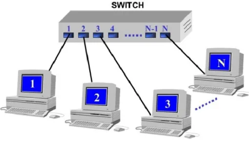
With the decreasing cost of these devices, Ethernet topology migrated to the star one for the several advantages offered.
In this structure, every station is linked with a point-to-point line with the hub.
Figure 3: Switched Ethernet
The situation is definitely improved if the star centre is a level 2 device, like a switch, as shown in Figure 3. These devices, in fact, are able to process more frames simultaneously, allowing supplying to every user the maximum speed available on the network.
Thanks to the switch adoption, there is the additional advantage to divide the network in more collision domains, even making every device be in a single collision domain, completely avoiding collisions. This significantly improves network performances because switches can make integrity checks on frames in circulation on the network, discarding bad frames. The disadvantage of this kind of control is the delay introduced by the check operation. Consequently, different switching policies have been studied to reduce the introduced latency.
In the following subchapters, two relevant physical layers (also referred as PHYs) will be discussed; these are the most relevant for feasibility and characteristics in Ag mobile environments.
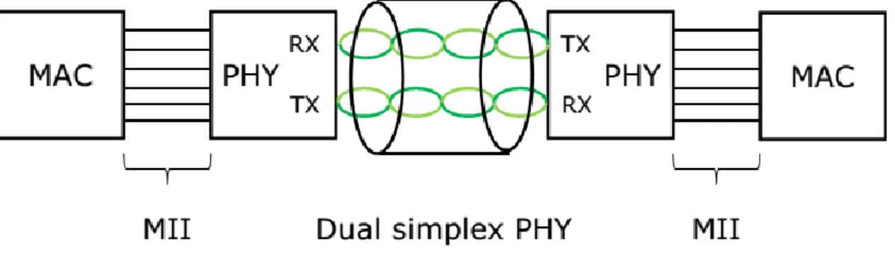
3.3.1 IEEE 802.3 100-baseTX
100BASE-TX is the predominant form of Fast Ethernet, and runs over two wire-pairs inside a category 5 or above cable (Figure 4). Each network segment can have a maximum cabling distance of 100 meters (328 ft). In its typical configuration, 100BASE-TX uses one pair of twisted wires in each direction, providing
12
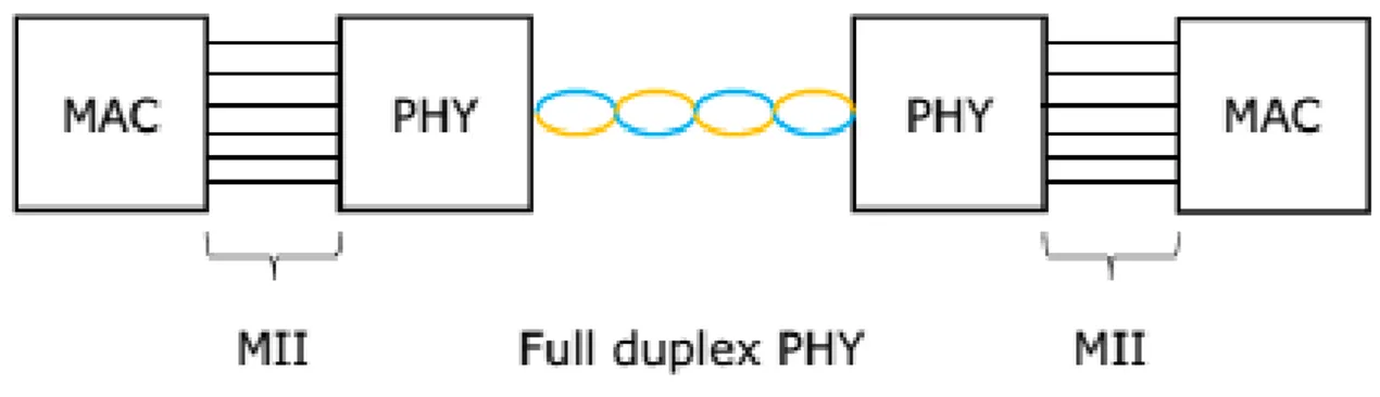
100 Mbit/s of throughput in each direction (full duplex), this is obtained by using a dual simplex communication.
The configuration of 100BASE-TX networks is very similar to 10BASE-T. When used to build a local area network, the devices on the network (computers, printers etc.) typically connects to a hub or switch, creating a star network. Alternatively, it is possible to connect two devices directly using a crossover cable.
Figure 4: 100base-TX basic network topology
With 100BASE-TX hardware, the raw bits (4 bits wide clocked at 25 MHz at the MII) go through 4B5B binary encoding to generate a series of 0 and 1 symbols clocked at 125 MHz symbol rate. The 4B5B encoding provides DC equalization and spectrum shaping (see the standard for details).
100BASE-TX introduces an additional, medium dependent sublayer, which employs MLT-3 as a final encoding of the data stream before transmission at 125Msps, using 65 to 80 MHz bandwidth.
3.3.2 O.P.E.N. Alliance Broadr-Reach
BroadR-Reach (OABR) [10] is a modified Ethernet physical layer designed by Broadcom for use in automotive connectivity applications.
One of the most important advantages is that it has been designed to use a single twisted pair cable (Figure 5). This characteristic denote OABR vocation for automotive. In fact, Broadcom had a special care in the development of this standard to let it fit to automotive area requirements: low cost and lightweight cabling, low power and cost-efficient components, robust operation under severe noise conditions.
13
Figure 5: BroadR-reach basic network topology
The objectives that characterized OABR development are:
To provide a PHY that supports full duplex operation at 100 Mb/s over one pair unshielded twisted pair or better cable for at least 15 m;
Provide compatibility with the MII and IEEE 802.3 MAC operating at 100 Mb/s; Maintain a BER of less than or equal to 1.0E-10 at the MAC interface;
Support 100 Mb/s operation in automotive and industrial environment.
Support a start-up procedure which enables the time from power on to valid data to be less than 200 ms;
The PHY needed to have some peculiar characteristics. First of all Broadcom tried to use as more as possible already proven technologies of IEEE standard to support a single pair Automotive Cabling connection, to reach up to 15 meters.
PHYs are also optimized for Automotive EMC requirements. To enhance EMC performance the TX Power Spectral Density has been shaped to fit Automotive Emissions Masks, in particular it has been used a PAM-3 modulation for high noise immunity and DSP-based receiver technologies, using DFE and Echo Cancellation for FDX operation.
A comparison between standard Ethernet and OABR PHYs highlights an improved immunity and lower emission characteristics for the latter.
A system overview can show that the OABR channel uses, as anticipated in the lines above, a PAM3 modulation to reduce Electromagnetics Emissions and has a bandwidth of 33.3 Mhz, which grants a baud rate of 66.6 Mbaud.
The mode of operation is a FDX w/Echo cancellation and the transmission Power Spectral Density respect both lower and upper automotive emissions masks.
14
The PHY synchronization is realized thanks to a loop timing, the signal mapping is a 3B2T and the equalization is receiver-based. As the transmitter and receiver must be clocked from the same source to grant echo cancellation, the communication has a master that provides with a fixed-frequency clock to one slave.
OABR is under IEEE standardization as a communication standard being part of the IEEE 802.3 family [6] and the first release is expected for the end of 2015.
15
4 The TCP/IP stack
4.1 IP
Internet Protocol is conceived to be used in interconnected systems of packet switching networks. It transmits data blocks called “datagrams” from a source to a destination, identifying it through fixed length addresses. It provides the possibility to fragment and reassemble datagrams both when a datagram has a big size and when the MTU of the network is smaller than datagram’s size.
IP is specifically designed to deliver a datagram from a source to a destination through an interconnected networks system. No mechanisms that increase end-to-end data reliability or that grant flow control, sequentiality or other services are found in other host-to-host protocols.
This protocol is called from host-to-host ones to take internet datagrams to destination.
IP modules uses the addresses reported in IP header to take IP datagrams to destination. The selection of a path for transmission is called routing. IP modules use header’s fields to fragment and reassemble internet datagrams when necessary. The operative model requires that there is an internet module per each host interested in communication. These modules will share the rules to parse the address fields and to fragment and assemble datagrams. These modules has also procedures to make decisions about routing.
IP treats each datagram as an independent entity, not correlated to each other. There are no connections or logical circuits.
To supply the service, four key mechanisms are used: Type of Service, Time to Live, Options and Checksum:
Type of service (TOS): it is used to indicate desired service typology. A parameter set characterize the services choice taken in those networks that builds internet. These indications can be used by the routers to:
o select current transmission parameters; o select the network to be used for next hop; o select next host when routing an IP datagram;
16
Time to live (TTL): it is an indication of the upper limit on a datagram lifetime. Its set by the device that sends the datagram and is reduced of a unit at each host that process packet’s route. If TTL reaches zero before the datagram has arrived to destination then it is discarded.
Options: this field provides necessary control functions or, however, useful functions for some situations, but not necessary for most common communications. These options include information like the timestamp, information for security and special routing.
Checksum: it provides a verification that the information used in processing the datagram have been correctly transmitted. If errors are revealed then the datagram will be discarded by the entity that discovers it.
IP does not supply a reliable communication: no acknowledge are provided (nor end-to-end or hop-to-hop). There is no error control mechanism on data, but only on header. No retransmission or flow control mechanism is provided.
If any error is found Internet Control Message Protocol (ICMP) notices it back to the source host.
About addressing, it is necessary to make a distinction between name, address and route: the name is what it’s searching for, the address is where it can be found and the route is show to reach it. IP mainly works with addresses and the IP routing table. It is going to be an upper level’s task to map names into addresses, typically the Domain Name System (DNS) and to construct the routing table, either using a routing protocol such as OSPF (Open Shortest Path First) or RIP (Routing Information Protocol) or a static routing table.
Addresses have a fixed length of 32 bits. They begin with a network number, followed by a local address. There are three classes of internet addressing:
Class A: most significant bit is set to zero, the following seven define the network and the last 24 are the local address;
Class B: the first couple is 10, the following 14 define the network and the last 16 are the local address;
Class C: the first three bits are 110, followed by 21 bits describing the network address, while the last 8 bits are the local address.
17
It has requested a particular attention in mapping internet addresses to local network’s addresses. A single physical host can be able to work like if there are different hosts. Some hosts also have different physical interfaces (multi-homing).
The fragmentation of an internet datagram is necessary when the packet generated in a local network that allows big packages have to cross networks that limits packets to smaller sizes. A datagram can also be marked as non-fragmentable. In this case, if it exceeds network maximum dimensions it is going to be discarded. The fragmentation and reassembly procedure needs to be able to split the datagram in an arbitrary number of pieces that will be reassembled later. The fragment’s receiver uses the identification field to ensure that different datagram’s pieces are not mixed. The “fragment offset” field indicates in which position the fragment has to be placed to rebuild the packet. The “more fragments” field indicates the last fragment. These fields provide enough information to rebuild the datagram.
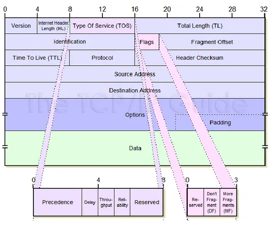
Figure 6 shows an IP header’s structure. It is going to be analysed the function of different fields:
IHL: 4 bits. It is the IP header’s length indicated in 32-bit word’s terms. The minimum value for a correct header is 5.
Type of service: 8 bits. Indicates abstract parameters of the specific service typology. These parameters will be used to guide the selection of service’s parameters in datagram transmission. In fact, different networks offers different priority for various services. The major choice is a three-way trade-off between low delay, high reliability and high throughput.
Total length: 16 bits. Indicates the length, in byte, of the datagram, including the header and data. A datagram length can reach 65536 bytes, even if this maximum length is not much used in hosts. However, every host has to support at least 576 bytes. This number is chosen to allow a reasonable data block dimension to be transmitted added to header’s information.
Identification: 16 bits. Identification number assigned by the sender to help in datagram fragments reassemble.
Flags: 3 bits. Various control flags.
Fragment offset 13 bits. Indicates where it has positioned the received fragment in the complete datagram.
18
Time to live: 8 bits. Indicates the number of maximum hops that a datagram can have. Protocol: 8 bits. Indicates the upper level protocol used in the data portion of the datagram. Checksum: 16 bits. Header’s checksum.
Source address: 32 bits. Destination address: 32 bits.
Options: variable. This field can appear or not in a datagram. However, every IP module must implement the options. Only the transmission in datagrams is optional.
Padding: variable. Used to make the header’s length to be multiple of 32 bits.
19
4.2 ICMP
Internet Control Message Protocol (ICMP) is a protocol for the IP signalling, and as such is an integral part of IP. Every ICMP packet has a structure dependent on the kind of signalling, that is bringing and the constant and qualifying parts are only in the first 32-bits.
They contains:
ICMP message type (8-bit);
ICMP code (8-bit) for the particular message type; Checksum (16-bit)
Although the signalling messages are varied, it is interesting to consider the most significant, classified according to their function:
Error Report.
Characteristic ICMP are the following:
o “Destination Unreachable”, when a packet is discarded because it was not possible to reach the destination, for any opportunely specified reason.
o “Time Exceeded”, when a packet is discarded by a router as its TTL (Time To Live) has reached the maximum depth.
o “Parameter Error”, when a packet has a header with some parameter not well interpretable. Reachability test and Performances.
ICMP permits, through “Echo Request”, “Echo Reply” to verify the reachability of a machine or a router and establish the time required to communicate with it, using “Timestamp Request” or “Timestamp Reply”.
Congestion Control.
This feature allow, through “Source Quench”, to request a reduction of the packet transmission rate. Routing Changing.
Through the message “Redirect”, a router can inform a machine connected to the local network, to use an alternative router in the same network, to send packets to a specific destination.
20 Network Parameters Request
Other machines connected to the network, using “Address Mask Request”, “Address Mask Reply”, could request several parameters, such as the NET_MASK.
Some error messages could be used to set up dynamic configurations. For instance, the determination of the Maximum Transmission Unit (MTU) of a segment.
In fact, generally, is transmitted a MTU, with the indication of not to fragment. In this way, a system error is forced if the MTU was too high, with the transmission of an ICMP with indication about the error cause, but also with an indication of an adequate MTU value.
4.3 IEEE 802.1q (VLAN)
IEEE 802.1q specifies how the MAC Service is supported by Virtual Bridged Local Area Networks, the principles of operation of those networks, and the operation of VLAN-aware Bridges, including management, protocols, and algorithms.
VLANs defines ways to virtually partition a physical network, so that different sub-networks are created. Usually, VLANs are adopted in corporate buildings to divide in branches different compartments of the same firm, to differentiate and isolate traffic, allowing sharing of contents just inside these divisions. Typical issues addressed by VLANs are:
• Scalability, over one physical network, sparse hosts can separated from others without placing new cables;
• Security, a careful segmentation of the network allows traffic encapsulation so that only hosts belonging to a certain subnet can communicate with each other;
• Improvements in network management, in a “divide et impera” fashion, where smaller groups of host can be better manageable.
IEEE802.1Q specifies the modifications to a standard Ethernet frame adding to the end of the standard Ethernet frame header four octets. These are divided as follows:
• Tag Protocol Identifier: a 16-bit field set to 0x8100 that identifies the frame as a compliant IEEE802.1Q one;
21
• Drop Eligible bit: used to indicate if a frame is eligible to be dropped in case of heavy traffic; • VLAN Identifier (VID), a 12-bit field that specifies the VLAN to which the frame belongs.
So, 4094 VLANs are feasible and each can be ranked in 8 different types of priority, whose description can be found in IEEE802.1P. As relevant standards (ISO 11783 for agricultural machines and SAE J1939 for heavy-duty machines) provides with 65535 application streams, hence grouping should be made, but reasonably easy to perform.
22
5 Industrial Ethernet Fieldbuses and AVB
This chapter deals with relevant fieldbuses and standards, which modifies either IEEE 802.3 or protocols of upper OSI levels.
Paragraph 5.1 lists the selected criteria for evaluate different aspects of the Fieldbuses. In the next paragraphs, these criteria will be examined for each fieldbus selected. Particularly, we will focus on four fieldbuses, AVB (Audio-Video Broadcasting), EtherCAT, POWERLINK and TTEthernet (Time-Triggered Ethernet).
After all, the considerations that emerged will be compared in 5.6.
5.1 Criteria
5.1.1 Technical aspects
BroadR-Reach Compatibility
EMC Susceptibility/Transmission Reliability Flexible Cabling Topology
o Tree Topology o Star Topology o Ring Topology o Daisy-Chain Topology High Availability o Ring Redundancy
o Master and Cable Redundancy Hot Plugging Capability
Gigabit Readiness Products on the Market
Communication Architecture of the Systems o Centralized Control
23
5.1.2 Performance
Direct Cross-Traffic
Heavy Data Traffic (Prioritization)
Network Load for Safety Communication Capability to support mixed traffic
5.1.3 Implementation Costs
Master Implementation
Costs for Potentially Required Network Components o External Devices (External Switches or Hubs) o Internal Multiport Slave Implementation Operating Costs License Fee AUTOSAR support
5.2 AVB
5.2.1 Introduction
Audio Video Bridging (AVB) is a common name for a set of technical standards developed by the Institute of Electrical and Electronics Engineers (IEEE) Audio Video Bridging Task Group of the IEEE 802.1 standards committee. This task group had been renamed to Time-Sensitive Networking Task Group at November 2012 to reflect the expanded scope of work. The charter of this organization is to "provide the specifications that will allow time-synchronized low latency streaming services through IEEE 802 networks".
These consist of:
IEEE 802.1BA: Audio Video Bridging (AVB) Systems;
IEEE 802.1AS: Timing and Synchronization for Time-Sensitive Applications (gPTP - Generalized Precision Time Protocol);
IEEE 802.1Qat: Stream Reservation Protocol (SRP);
24
IEEE 802.1Qat and 802.1Qav are amendments to the base IEEE 802.1Q document, which specifies the operation of "Media Access Control (MAC) Bridges and Virtual Bridged Local Area Networks", which are implemented by network devices typically called Ethernet switches. Audio and video (AV) equipment connections historically were analog one-way, single-purpose and point-to-point. Even digital AV standards often were point-to-point and one-way such as S/PDIF for audio and the serial digital interface (SDI) for video. This connection model resulted in large confusing masses of cables, especially in professional and high-end consumer applications.
Attempts to get around these problems included new technologies such as IEEE 1394 (known as FireWire), and adaptations of standard computer network technologies such as Audio over Ethernet or Audio over IP.
Specialized professional, home, and automotive protocols did not interoperate. Adapting standard networks could use commodity technology, but tight quality of service control was difficult.
An “Audio Video Bridging” (AVB) network implements a set of protocols being developed by the IEEE 802.1 Audio/Video Bridging Task Group. There are four primary differences between the proposed architecture and existing 802 architectures:
Precise Synchronization (IEEE 802.1AS),
Traffic shaping for AV streams (IEEE 802.1Qav), Admission Controls (IEEE 802.1Qat),
Identification of non-participating devices (IEEE 802.1BA).
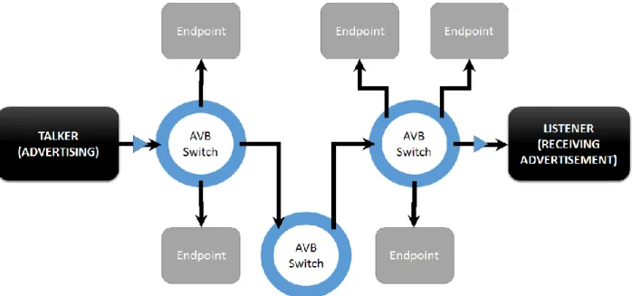
These are implemented using relatively small extensions to standard layer-2 MACs and bridges. This “minimal change” philosophy allows non-AVB and AVB devices to communicate using standard IEEE 802.3 frames. However, as shown in Figure 7, only AVB devices are able to:
a) reserve a portion of network resources through the use of admission control and traffic shaping b) send and receive the new timing-based frames.
25
Figure 7: AVB Network Example
Precise Synchronization – 802.1AS gPTP (Generalized Precision Time Protocol)
AVB devices periodically exchange timing information that allows both ends of the link to synchronize their time base reference clock very precisely.
This precise synchronization has two purposes: To allow synchronization of multiple streams
To provide a common time base for sampling/receiving data streams at a source device and presenting those streams at the destination device with the same relative timing.
The protocol used for maintaining timing synchronization is specified in IEEE 802.1AS, which is a very tightly-constrained subset of another IEEE standard, IEEE 1588 PTP (Precision Time Protocol), with extensions to support IEEE 802.11 and also generic “coordinated shared networks” (CSNs).
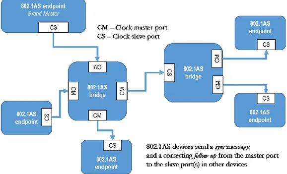
26
An 802.1AS network-timing domain is formed when all devices follow the requirements of the 802.1AS standard and communicate with each other using the IEEE 802.1AS protocol. Within the timing domain, there is a single device called the grandmaster that provides a master timing signal. All other devices synchronize their clocks with the Grand Master as shown in Figure 8.
The device acting as Grand Master can be either auto selected or specifically assigned. AVB devices typically exchange capability information after physical link establishment. If peer devices on a link are network synchronization capable, they will start to exchange clock synchronization frames. Otherwise, then an AVB timing domain boundary is determined (as shown in Figure 7).
Figure 8: Example of clocking hierarchy
Traffic Shaping for AV Streams – 802.1Qav FQTSS (Forwarding and Queuing of Time-Sensitive Streams)
In order to provide professional AV services, the AVB architecture implements traffic shaping using existing IEEE 802.1Q forwarding and priority mechanisms but also defines a particular relationship between priority tags and frame forwarding behaviour at endpoints and bridges. Traffic shaping is the process of smoothing out the traffic for a stream, distributing its packets evenly in time. If traffic shaping is not done at sources and bridges, then the packets tend to “bunch”, i.e. agglomerate, into bursts of traffic that can overwhelm the buffers in subsequent bridges, switches and other infrastructure devices.
27
AVB streams consist of IEEE 802.3 frames with priority tagging and with normal restrictions on format and length. The default IEEE 802.1Q tagging for a particular market segment should be chosen to avoid potential conflict with existing uses of the IEEE 802.1Q priority tags, within that market segment.
Endpoint devices are required to transmit frames evenly for a particular stream based on the AVB traffic class and on the specific Quality of Service (QoS) parameters that were used when the stream was acknowledged by the network (see Admission Controls below). The specific rules for traffic shaping are described in the IEEE 802.1Qav specification, and are a simple form of what is known as leaky bucket credit-based fair queuing where the bandwidth reserved for a stream controls the time between the packets that make up the stream.
AVB frames are forwarded with precedence over Best Effort traffic (i.e., reserved AVB stream traffic traversing an AVB bridge has forwarding precedence over non-reserved traffic) and will be subjected to traffic shaping rules (they may need to wait for sufficient credits). Just like for stream sources, the traffic shaping rules for bridges require that frames should be distributed evenly in time, but only on an aggregate class basis rather than on a per-stream basis. This means that all the AVB traffic being transmitted out of a particular port is distributed evenly in time measured using the QoS parameters of that class; this is the sum of the bandwidths of all the reservations for a particular AVB class for the particular port, made by the admission control process described below. This is to achieve the effect of smoothing out the delivery times (preventing “bunching” of frames) while a stream propagates through a network. The limited “bunching” provides the very useful benefit of placing a relatively small upper limit on the size of the AVB output buffers needed at all egress ports on a bridge, independent of the number of hops in the path. This bounded buffer size is a key attribute that enables bounded delay and eliminates network congestion for admitted AV streams in AVB networks even when non-admitted traffic does experience congestion.
Admission Control – 802.1Qat SRP (Stream Reservation Protocol)
In the AVB protocols, the term “talker” denotes a stream source while “listener” denotes a stream destination. In this architecture, it is both the talker’s and the listener's responsibility to guarantee the path is available and to reserve the resources. The process to do this is specified by the IEEE 802.1Qat “Stream Reservation Protocol” (SRP), which registers a stream and reserves the resources required through the entire path taken by the stream.
28
Phase 1. Talkers initiate by sending an SRP “talker advertise” message. This message includes a Stream ID composed of the MAC address of the stream source plus a talker-specific 16-bit unique ID and the MAC address of the stream destination. Additionally, the “talker advertise” message includes QoS requirements (e.g., AVB traffic class and data rate information), and accumulated worst-case latency. Even though the talker originates the address and QoS requirements, the worst-case latency is recalculated at every bridge allowing the listener to communicate this information to higher layers for media synchronization purposes.
All AVB intermediate bridges receiving a “talker advertise” message check for bandwidth availability on their output ports. When the bridge has sufficient resources available on that port, the “talker advertise” is propagated to the next station. If those resources are not available, instead of propagating the advertise message, the bridge sends a “talker failed” message. Included in this message there is a failure code and bridge identification allowing a higher-layer application to provide error checking or notification. An intermediate bridge receiving a “talker failed” should just pass on the message out towards the listener. When a listener receives a "talker advertise” message, it should know whether the resources are available, and if so, the latency for the path.(Figure 9).
Figure 9: Step 1 for Stream Reservation Protocol
Phase 2. The listener can respond with a “listener ready” message that is forwarded back towards the talker. Intermediate bridges use the “ready” message to lock down the resources needed by the stream and to make the appropriate entries in their forwarding database to allow the stream to be sent on
29
the port that received the “ready” message. When the talker receives a “ready” message, it can start transmitting the stream (Figure 10).
Figure 10: Step 2 for Stream Reservation Protocol
Phase 3. Talker endpoint sends stream and listener endpoint receives it (Figure 11).
30
The talker can explicitly tear down a stream by de-registering the “talker advertise”, and a listener can disconnect by de-registering the “listener ready”. A de-registration message propagates through the network in the same manner as the original registration.
There are also implicit methods used for tearing down a connection and for releasing the allocated resources. For example, the listener must periodically resend registrations and “ready” messages, and talkers must periodically resend “advertise” messages. That way any receiving device (including intermediate bridges) could automatically release assigned resources and notify higher layers if the appropriate registrations and reservations were not received due to a system that, for example, suddenly has lost power.
AVB network are becoming fairly diffuse in automotive environment, especially in high-end cars. [11] provides a comparison with new generation network w.r.t. old ones.
Identification of participating devices – 802.1BA AVB Systems
Since the whole AVB scheme depends on the participation of all devices between the talker and listener, any network element that does not support AVB (including so-called “unmanaged bridges”) must be identified and flagged. The developing IEEE 802.1BA “Audio Video Bridging Systems” standard describe this process, which specifies the default configuration for AVB devices in a network. For Ethernet, the method specified by 802.1BA to determine if its peer is AVB capable is a combination of 802.3 link capabilities (determined during Ethernet link establishment) and the link delay measurements done by IEEE 802.1AS. An AVB capable Ethernet port uses AVB if:
1. The link is full duplex with a rate of 100Mbps or 1Gbps; 2. The 802.1AS protocol discovers exactly one peer;
3. The round-trip delay to the responding AVB device is no more than a worst-case wire delay;
4. An SRP reservation request or acknowledge is received on the port
5.2.2 Technical aspects
BroadR-Reach Compatibility:
Audio Video Bridging is fully-compatible with the BroadR-Reach physical level, EMC Susceptibility/Transmission Reliability:
31 Flexible Cabling Topology:
AVB supports all the possible following depicted network topology. The only limitation is in use of Daisy-Chain topology, where the path delay can grow up and exceed the real time streaming requirements. Generally is implemented a little switch, instead of two separated PHY (ports).
o Tree Topology ( + ) o Star Topology ( + ) o Ring Topology ( + ) o Daisy-Chain Topology ( 0 ) High Availability:
AVB presents a high availability, especially for AVB streams, in which constant high-level signalling messages are exchanged between the communication entities.
o Ring Redundancy ( + )
o Master and Cable Redundancy ( + ) Hot Plugging Capability:
This feature is fully supported by the aid of Stream Reservation Protocol. Gigabit Readiness:
AVB can easily supported on Gigabit networks, also thanks to the Stream Reservation Protocol, which can reserve more bandwidth for the communication.
Products on the Market:
Many products with AVB are present on the market, but principally for Industrial or Consumer applications. Nowadays are popping switches automotive-certified, which supports also BroadR-Reach physical level.
Communication Architecture of the Systems: the network architecture is flat-type, in the sense that there is any “Communication Master”. To complete the synchronization, A Grand Master is present, but the control and the communication is de-centralized (i.e. the switches, with SRP). If a Grand Master fails, any other available end-point can be elected as new Grand Master for the synchronization.
o Centralized Control ( - ) o De-centralized Control ( + )
32
5.2.3 Performance
Direct Cross-Traffic:
Because AVB constitutes a de-centralized control system, is possible to make direct-cross traffic.
Heavy Data Traffic (Prioritization):
In AVB, Heavy Data Traffic is well supported, thanks to the Stream Reservation Protocol, which reserves all the necessary resources for the transmission of a stream. This kind of traffic does not take all the network’s available resources, because it can take up to the 75% of the available bandwidth. In this way, Best Effort Traffic cannot starve in an AVB switch’s buffer. Moreover, thanks to the two different priority classes (AVB class A and AVB class B streams), traffic can be sent from talker to listener station with different priorities, making more simple the stream of real-time information and the appropriate traffic shaping assures both throughput and delivery latency parameters are met for packets of reserved streams.
Network Load for Safety Communication:
Thanks to Stream Reservation Protocol, all the safety communication can be easily supported and the bandwidth reserved.
Capability to support mixed traffic:
With AVB, mixed traffic is fully supported, because standard Ethernet communications can be wrapped into a Best Effort messages. However, for support AVB traffic is necessary to use proper switches.
5.2.4 Implementation Costs
Master Implementation: N/A.
Costs for Potentially Required Network Components:
AVB requires a strong traffic control, over layer 3. This push the use of software stack or hardware solutions (ASICs). In both cases, the cost of the network system grows. Moreover, when the protocol’s stack is implemented by software, it is necessary a
33
powerful microcontroller/microprocessor and this push the developer to oversize the embedded system, selecting a higher-level microcontroller, than the one actually required. However, many devices on the market integrates AVB themselves and therefore, adopting this technology will become cheaper.
o External Devices (External Switches or Hubs):
An AVB network requires specific switches certified for AVB. The cost for this hardware is higher than other Ethernet solutions.
o Internal Multiports:
Internal Multiports are cheaper object than external switches.
Slave Implementation: Peer implementation needs the stack layer 1 and 2 to be embedded in the network interfaces. For switches, specific devices are required and have to be designed to support IEEE 1588 and IEEE 802.1AS timing functions.
Operating Costs: There are no operating costs related to AVB use.
License Fee: There is no license fee related to the use of AVB.
AUTOSAR support: AUTOSAR 4.2.1 introduces basic support for AVB and further extensions have been proposed.
5.3 EtherCAT
5.3.1 Introduction
EtherCAT (“Ethernet for Control Automation Technology”) was developed by Beckhoff Automation. All users of this technology automatically become members of the EtherCAT Technology Group (ETG). EtherCAT is based on the summation frame method: the EtherCAT Master transmits an Ethernet frame containing data for all nodes on the network. That frame passes through all nodes in sequence. When it arrives at the last node on a trunk, the frame is turned back again.
The nodes process the information in the frame as it passes through in one direction. Each node reads out data addressed to it on the fly, and inserts response data back into the frame. In order to support the
34
bandwidth of 100 Mbit/s, special hardware based on ASICs or FPGAs is required for fast processing as data passes through. In effect, the topology of an EtherCAT network always constitutes a logical ring. Even trunks branching out, which can be hooked up to nodes especially designed for such connections, actually only add a two-way junction where the summation frame telegram travels up and back down the branching line.
Figure 12: EtherCAT packet example
All EtherCAT telegrams with instructions for individual nodes are contained within the payload data area of a frame, as shown in Figure 12. Each EtherCAT frame consists of one header and several EtherCAT commands. Each of these comprises its own header, instruction data for a slave, and a working counter. Up to 64 Kbytes, configurable address space is available for each slave. Addressing proceeds by auto-increment, i.e. each slave counts up to the 16-bit address field. Slaves can also be addressed via distributed station addresses, which are assigned by the Master in the start-up phase.
Every slave connection provides a real-time clock that is synchronized by the master using a technique similar to IEEE 1588. There are slave devices with and without real-time mechanisms, since these are more demanding on the hardware. Based on the real-time clocks, control signals can be synchronized with high precision. In physical terms, the EtherCAT protocol not only runs on Ethernet, but also on LVDS (Low Voltage Differential Signalling). This standard is used by Beckhoff as an internal bus on the terminals. A PC with a standard Ethernet interface is typically used to implement an EtherCAT master. [12, 13, 14] give some examples of applications in safety-relevant environment
5.3.2 Technical aspects
BroadR-Reach Compatibility: An implementation of EtherCAT Fieldbus over BroadR-Reach is possible only after a complete re-design of the ASIC (or FPGA
35
implementation) due to the different Physical layer.Another possibility is to make a retrofit, with a protocol translation, inserting a BroadR-Reach to Ethernet adaptor on each port of the device.
EMC Susceptibility/Transmission Reliability: Due to summation frame protocol, Ethercat is more susceptible to interference than a single frame protocols. If a frame is destroyed, summation frame protocols always lose an entire cycle.
Flexible Cabling Topology: EtherCAT networks always constitute a logical ring. That ring can be physically closed at the master, or, in the case of a daisy chain, closed internally at the last node in the physical line. EtherCAT does provide for trunks to branch out via special junctions, but the entire frame travels up and back down such lateral network lines, i.e. the network as a whole still represents a logical ring.
o Tree Topology ( - ) o Star Topology ( - ) o Ring Topology ( + )
o Daisy-Chain Topology ( + )
High Availability:
EtherCAT has a self-redundancy given by the logical ring, where the information passes twice through the same node. No type of Master and cable redundancy is implemented.
o Ring Redundancy ( + )
o Master and Cable Redundancy ( 0 ) Hot Plugging Capability:
EtherCAT has some restrictions due to the compulsory ring topology and provides some hot plugging capability. In the EtherCAT Slave Controller, open ports are automatically closed if no link is detected. EtherCAT’s distributed clocks, however, requires re-synchronization, which may affect certain applications.
36
Gigabit Readiness: EtherCAT can be scaled to Gigabit, but requires an ASIC redesign. If it is implemented by an FPGA solution, it can be ported to Gigabit.
Products on the Market: Many EtherCAT products can be found on market.
Communication Architecture of the Systems: Due to the presence of a Master into the communication architecture, is also possible a centralized control.
o Centralized Control ( + ) o De-centralized Control ( - )
5.3.3 Performance
Direct Cross-Traffic: Due to logical ring network topology, direct cross-traffic is not allowed.
Heavy Data Traffic (Prioritization): In applications involving a large volume of process data, the time required for passing through the nodes greatly impacts the overall
cycle time.
For EtherCAT, solutions for this requirement can be implemented as part of a specific application.
Network Load for Safety Communication: Safety over Ethernet is based on a cyclic exchange of protected data between safety nodes (emergency stop switches, drives with Safety controllers). The safeguard procedures in this process involve data duplication and wrapping data in safe “containers”. This increases data rates on the network. Solutions using the summation frame method will see the frame count go up, whereas the single frame method will increase the volume of data in each of the frames that are due to be sent anyway. Overall, the theoretically superior performance of the summation frame method is neutralized.
37 Capability to support mixed traffic:
In the case of insertion of an Ethernet device, it could be cause a collision into the packet. Supposing the insertion of Ethernet device between Master and the first daisy-chain Slave, if the Ethernet device sends a message to the Master, if it does not collide any other message on the network, it will be probably ignored by level 3 of the Master’s ISO/OSI stack.
If the message is sent to a generic Slave in the daisy chain, if it can reach the destination Slave, it will be ignored.
5.3.4 Implementation Costs
Master Implementation:
EtherCAT master runs on standard hardware, so any Ethernet MAC are suitable. The software stack for enabling EtherCAT communications are provided by several manufacturers and for different operating systems. Master access is patent-protected and no open source master is suitable, but only sample code that does not warrant applicability.
Costs for Potentially Required Network Components:
EtherCAT requires specific network components, especially for star or tree topologies. Therefore, specific switches are needed and internal multiport is implemented by the use of specific ASIC developed by Beckhoff.
o External Devices (External Switches or Hubs) ( - ) o Internal Multiports ( - )
Slave Implementation:
EtherCAT slaves require custom hardware such as ASIC or FPGA controllers. The costs for slave hardware are based on the controller capabilities and device manufacturer. Usually the costs are comparable to any other fieldbus controller.
38
For EtherCAT, microcontroller-based software solutions are also feasible.
Operating Costs:
There are no operating costs related to EtherCAT use.
License Fee:
There is no license fee related to the use of EtherCAT, it is embodied into hardware/software costs.
AUTOSAR support: N/A
5.4 Powerlink
5.4.1 Introduction
Initially developed by B&R, POWERLINK was introduced in 2001. The Ethernet POWERLINK Standardization Group (EPSG), an independent user organization with a democratic charter, has taken charge of the further development of the technology since 2003. POWERLINK is a completely patent-free, vendor-independent and purely software-based communication system that delivers hard real-time performance. An open source version has also been made available free of charge in 2008.
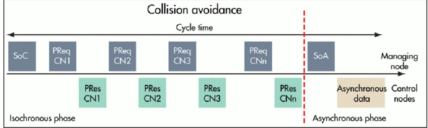
POWERLINK fully complies with the IEEE 802.3 Ethernet standard, i.e. the protocol provides all standard Ethernet features including cross-traffic and hot plugging capability, and allows for deploying any network topology of choice. It uses a mixture of timeslot and polling procedures to achieve isochronous data transfer. In order to ensure co-ordination, a PLC or an Industrial PC is designated to be the Managing Node (MN). This manager enforces the cycle timing that serves to synchronize all devices and controls cyclical data communication.
All other devices operate as Controlled Nodes (CN). During a cycle, the MN sends so-called “Poll Requests” (PReq) to one CN after another in a fixed sequence. Every CN replies immediately to this request with a “Poll Response” (PRes) on which all other nodes can listen in.
39
Figure 13: Different phases in a POWERLINK communication cycle
A POWERLINK cycle consists of three periods, as depicted in Figure 13. The first is the “Start Period”, where the MN sends a “Start of Cycle” (SoC) frame to all CNs to synchronize the devices. Jitter amounts to about 20 nanoseconds.
Cyclic isochronous data exchange takes place during the second period (“Cyclic Period”). Multiplexing allows for optimized bandwidth use in this phase. The third period marks the start of the asynchronous phase, which enables the transfer of large, non-time-critical data packets. Such data, e.g. user data or TCP/IP frames, is scattered between the asynchronous phases of several cycles. In this last phase, the Managing Node grants the right to one particular node for sending ad-hoc data, by sending out the Start of Asynchronous (SoA) frame. Modifications [15] have been proposed to Powerlink in order to increase ASYNC service functionalities.
The addressed node will answer with ASnd frame. Standard IP-based protocols and addressing can be used during this phase.
POWERLINK distinguishes between real-time and non-real-time domains. Since data transfer in the asynchronous period supports standard IP frames, routers separate data safely and transparently from the real-time domains.
The quality of the Real-Time behaviour depends on the precision of the overall basic cycle time. The length of individual phases can vary as long as the total of all phases remain within the basic cycle time boundaries. The MN and the duration of the isochronous monitor adherence to the basic cycle time and the asynchronous phase can be configured.
40
5.4.2 Technical aspects
BroadR-Reach Compatibility: POWERLINK appears to be fully-compatible with Reach networks. An academic proof of concept on POWERLINK over BroadR-Reach is already present in the literature [15].
EMC Susceptibility/Transmission Reliability: POWERLINK uses a series of Broadcast or Unicast messages during the various phases. For do this, a standard Ethernet packetized communication is used. This allow a reliable communication and the EMC Susceptibility is the same of Ethernet.
Flexible Cabling Topology: The POWERLINK network’s topology architecture can be the same of Ethernet, with the use of the same PHY.
o Tree Topology ( + ) o Star Topology ( + ) o Ring Topology ( + )
o Daisy-Chain Topology ( + )
High Availability: POWERLINK has master and cable redundancy included in the specifications, and been implemented in actual projects.
o Ring Redundancy ( + )
o Master and Cable Redundancy ( + )
Hot Plugging Capability: Based on standard Ethernet protocol, POWERLINK fully supports hot plugging.
Gigabit Readiness: The original physical layer specified was 100BASE-TX Fast Ethernet. Since the end of 2006, Ethernet POWERLINK with Gigabit Ethernet
41
supported a transmission rate ten times higher (1,000 Mbit/s). As POWERLINK is entirely software-based technologies, this protocol can also be used with Gigabit Hardware.
Repeating hubs instead of switches within the Real-time domain is recommended to minimize delay and jitter.
Products on the Market: POWERLINK is a specific software implementation based on Ethernet. It can be implemented in every market.
Communication Architecture of the Systems: POWERLINK supports both
centralized and de-centralized controls.
o Centralized Control ( + ) o De-centralized Control ( + )
5.4.3 Performance
Direct Cross-Traffic: With POWERLINK, direct cross-traffic is a feature even for modules that only have slave functionality.
Heavy Data Traffic (Prioritization): In applications involving a large volume of process data, the time required for passing through the nodes greatly impacts the overall cycle time. Data prioritization, on the other hand, enables lower cycle times. Systems that support prioritization mechanisms allow for reading high-priority data once every cycle and polling for data with a lower priority only every n-th cycle. For POWERLINK, a variable cycle times has been firmly established in the protocols specifications.
Network Load for Safety Communication: Safety over Ethernet is based on a cyclic exchange of protected data between safety nodes (emergency stop switches, drives with
42
Safety controllers). The safeguard procedures in this process involve data duplication and wrapping data in safe “containers”. This increases data rates on the network. By the use of an Isochronous and Asynchronous Phases every cycle, it is guaranteed the Safety of Communications, especially in the real-time phase.
Capability to support mixed traffic: Due to fully-compatibility with Ethernet Standard communication, POWERLINK supports mixed traffic. The insertion of a non-POWERLINK device into the network should not create collision on the traffic during the communication.
5.4.4 Implementation Costs
Master Implementation: The openPOWERLINK software stack is open-source, so there is no additional costs related to its use. The hardware used for master controller nodes could be COTS device for standard Ethernet.
Costs for Potentially Required Network Components: In order to achieve maximum performances, only switched topology should be used, but hubs are supported. These devices could be standard Ethernet hubs/switches. For internal multiports, standard Ethernet multiport could be used.
o External Devices (External Switches or Hubs) ( + ) o Internal Multiports ( + )
Slave Implementation: As for master implementation no specific one is defined.
Operating Costs: POWERLINK has associated very low costs. Some features supported, such as hot-plugging capability or master-managed synchronization mechanism (that is very precise and very rarely disturbed by faults) permit to achieve very high performance with low design effort.