EAS 199
A Breadboard Primer
Fall 2012
Gerald Recktenwald
v: November 25, 2012 [email protected]
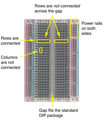
A breadboard is a rectangular array of small electrical sockets that is designed to enable rapid and easily reconfigured circuits. One typically builds a prototype circuit on a breadboard, and then transfers the circuit to a more robust layout such as a soldered perf-board or a printed circuit board. Figure 1 is an annotated image of a medium-sized breadboard. This style of breadboard is common. For example this is the style of breadboard included with the Arduino Inventors Kit. Beware that other styles with slight variations in the layout.
A breadboard is organized into rows and columns of electrical sockets. Those rows and columns can be further subdivided into groups. When the breadboard is oriented as in Figure 1, there are two outer pairs of columns with + and − labels. These are power rails that are used to supply a common voltage (say +5V or +12V ) and a common ground to the circuits in the main part of the board.
Between the power rails are two other groups of sockets. Again, referring to the orientation in Figure 1, these groups have letter labels at the top (a-e and f-j) and numerical labels along the left and right edges (1-30). Within these two central groups of sockets, only the rows of sockets are electrically connected. However, the two groups are not connected across the central gap. In other words, sockets a-e in row 8 are not connected to sockets f-j in row 8.
Rows are
connected
Power rails
on both
sides
Columns
are not
connected
Gap fits the standard
DIP package
Rows are not connected
across the gap
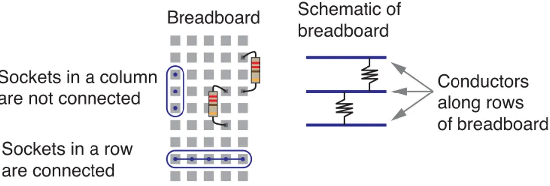
EAS 199 :: Breadboard Primer 2 Figure 2 shows how resistors in series are connected on a breadboard. Figure 3 show how resistors in parallel are connected on a breadboard.
Sockets in a column
are not connected
Sockets in a row
are connected
Breadboard
Schematic of
breadboard
Conductors
along rows
of breadboard
Figure 2: Resistors in series on a breadboard.