CIRTEN
Consorzio Interuniversitario per la Ricerca TEcnologica Nucleare
UNIVERSITA’ DI PISA
DICI
Assessment of the structural-dynamic effects caused by the
core compaction
Authors R. Lo Frano G. Forasassi G. Pugliese A. Sanfiorenzo CERSE-UNIPI RL 1540/2014 PISA, 1 September 2014Contents
List of Figures ... 2
Summary ... 3
1. Introduction ... 4
1.1 Physical problems to be addressed ... 5
2. Description of the system ... 8
2.1. ALFRED core design ...11
3. Core Compaction Analysis ... 13
4. Simulation of the dynamic transient ... 19
4.1. Initial and boundary conditions...19
5. Simulation of the dynamic transient ... 22
6. Conclusion ... 32
List of Figures
Figure 1 – Possible deformation of a subassembly. ... 4
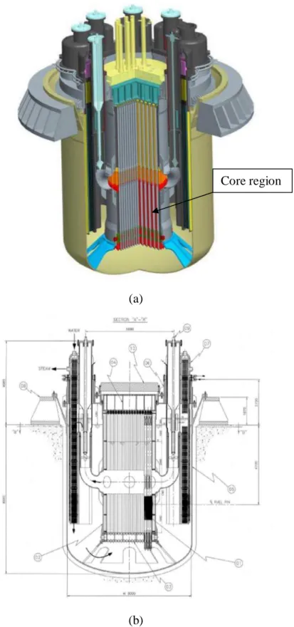
Figure 2 – ALFRED reactor scheme (a) and elevation view (b). ... 9
Figure 3 – General scheme of fuel restraints. ... 11
Figure 4 - Core and fuel assembly configuration. ... 11
Figure 5 – FEM model of the RV. ... 14
Figure 6 – FEM model of the inner cylindrical vessel: view (a) and vertical section (b). ... 14
Figure 7 – Details of the implemented FEM model of the lower grid: plates (a) and spacer grid (b). ... 15
Figure 8 – Details of the FEM model of the inner vessel: bottom part with lower late and diagrid (a) and upper part with flange for the positioning of upper grid (b). ... 17
Figure 9 – Details of the implemented FEM model of the upper grid. ... 18
Figure 10 – Detail of the connection between the lower and upper grid and the inner vessel. ... 19
Figure 11 – Accelerations Time Histories at the RV anchorage restraints. ... 21
Figure 12 – Von Mises stress without (a) and with contact and friction forces influence (b). ... 22
Figure 13 –Displacement along the overall inner vessel at 4 s and 5.5 s. ... 23
Figure 14 – Displacements along the overall inner vessel. ... 24
Figure 15 – Total displacement along the overall inner vessel. ... 25
Figure 16 – Total displacement close to the upper (green line) and bottom grid (red line). ... 25
Figure 17 – Von Mises stress distribution along the inner vessel at t = 5.75 s (a) and mean value far from the nozzle area (b). ... 27
Figure 18 –Contact normal force at the surface between upper (green line) and bottom grid (red line) and the inner vessel. ... 28
Figure 18 – Overall contact force at the lower (a) and upper grid (b). ... 29
Figure 19 – Total displacement close to the upper (green line) and bottom grid (red line). ... 29
Figure 17 – Von Mises stress distribution along the inner vessel at t = 5.45 s (a) and mean value far from the nozzle area (b). ... 31
Summary
Nuclear reactors have to be maintained in a critical state so as to keep the chain fission process stationary and under control. Nuclear stability considerations dictate that the geometry of the core be closely controlled at all times: therefore any modification of it must be predictable, compatible with the requirements of the interfacing reactor systems and safely manageable by (intrinsic and engineered) control mechanisms.
This study deals with the evaluation of the deformation of core (and restraint system) geometry due to dynamic perturbations that in some case could determine the compaction of core region, to a such extent, and possibly result in an insertion of reactivity.
To the purpose a finite element model of the overall reactor system and, specifically, of the inner vessel component that enclose and surround the core has been implemented in detail.
Suitable boundary and initial conditions, such as that one related to the core sub-assemblies mass, the restrictions imposed to the geometrical in-structures connections, etc. have been assumed to numerically investigate the dynamic response of the structures, since confidence was established by sensitivity analyses of size and type of the adopted elements carried out in the framework of PAR 2012.
The results of the analyses carried out are presented and discussed, highlighting also how the contact and friction forces (due to the contact condition mong internal structures) may influence the behaviour of structure and the evolution of compaction scenario.
The results will also represent the input data to adopt for further calculations on reactivity changes in the reactor core.
1. Introduction
This study focuses on the dynamic behaviour of the core structure (and restraint system) geometry of the ALFRED reactor and its deformations (that could in turn influence the reactivity excursions) caused particularly by dynamic loads. This assessment will give information for the safety control of the reactor and the upgrading of the core region design.
The compaction of the bundle of core assemblies (Figure 1 of [1]) is an important aspect of the core design with respect to its effect on the net reactivity during transient condition mainly caused by seismic event. Furthermore, under such a type of dynamic solicitation, the assemblies may distort inward as shown in Figure 1, increasing their possibility to displace, with respect to their nominal positions, then heightening the radial deformation or compaction of the core jointly to an insertion of reactivity.
Figure 1 – Possible deformation of a subassembly.
Three fundamental safety functions should be considered in the design of the core, for operational states and a wide range of accident conditions [1][2]:
· Reactivity control: a large compaction of the fissile material must be avoided and it must be demonstrated that under any kind of possible dynamic loading the core volume will not be decreased above a given limit. In order to limit possible reactivity insertion, relative movements between fissile subassemblies and absorber rods should be limited, and fuel pins break prevented. Moreover, it shall be demonstrated that the control rods are able to fall within the core during a dynamic excitation;
· Removal of heat from the core: the core is constituted of fuel assemblies in form of hexahedral tubes containing the fissile material. The liquid metal flows through these tubes and takes the energy out to the heat exchangers. Under dynamic loading, it must be demonstrated that the cooling capacity of the assemblies is not hindered;
· Material containment: the first barrier to prevent the spreading of fissile material to the environment is constituted by the fuel pins within the fuel assemblies. Under seismic loading, it must be demonstrated that these pins are not damaged to a level at which significant radioactive release from the core to the primary coolant could occur.
1.1 Physical problems to be addressed
Since the primary function is to provide the reactivity under control, any modification of the reactor core geometry must be predictable and safe. For instance, the core radial expansion causes changes in neutron leakage owing to the increase in core size and a decrease in the densities of fuel, cladding, and structural materials because the total material inventory remains unchanged. This core radial expansion results in a negative reactivity effect. Conversely, a reduction in core size results in a positive reactivity insertion [3].
Therefore in the design of a fast reactor core, the positions of the core assemblies and their interactions with each other and with the surrounding internal structures must be known and controlled in order to assure adequate safety and core performance.
This concern gives rise to the definition of core restraint requirements, which form the basis for the selection of specific design features for the core and internal components [3][4]. The major core restraint requirements include:
a. Reactivity: To enhance the inherent safety, a system for core assemblies support/restrain must be designed so to avoid as far as possible compaction phenomena, while allowing the thermal flowering of the elements during abnormal transients. This can be achieved by properly setting inter-assembly gaps along with anti-compaction pads on the periphery of the sub-assembly.
b. Assembly deformation: the high temperature and neutron flux environment together with lateral thermal and neutron flux gradients in the core region produce both temporary and permanent duct dilation and assembly bowing. Additional deformations may be induced by dynamic or
vibration loads. These effects can impact the ability to assure and maintain structural integrity of core components during normal core operation as well as during insertion and withdrawal processes.
c. Assembly alignment: Thermo-mechanical loads can also modify the alignment of the core assemblies with interfacing control and refuelling system components: the alignment of assemblies must be ensured within the envelope specified by the interfacing systems to avoid the inoperability of the control systems or the impairing of the subassembly manipulation itself.
d. Load Transmission: the need to limit and control core motions typically results in the definition of load transmission planes, identifiable at core and internals component elevations, where interfacing gaps are reduced. At these planes the components must be capable of sustaining and transmitting loads arising from normal reactor operation and accident condition, like during an earthquake event.
Several sources of dynamic loading on the core of such reactors have been identified. These sources include internal accidents, for example coolant boiling, and external accidents such as earthquakes or vibration induced by an airplane crash.
Among the consequences of deformations in the core region, the ones related to neutronic are those of most concern. While for Light Water Reactors the coolant also acts as moderator, so that a compaction of the core (hence, a reduction of the coolant volume fraction) not necessarily implies an increase of reactivity, in a Fast Reactor this is generally true.
In a Fast Reactor of commercial size, indeed, the core volume is such that the increase of neutron loss by leakage at the boundary is not sufficient to compensate the positive effects due to the hardening of the neutron spectrum, following the partial loss of coolant (LOF) from fuel sub-channels, nominally: an increase of the fission rates (notably in the “even” nuclides, having a threshold fission cross section) and a reduction of the capture rates.
Since it is not possible to exclude core compaction, no matter the number and robustness of the countermeasures adopted to prevent the initiating causes, it becomes of paramount importance to limit the compaction, through passive, simple and reliable means, so that the associated reactivity insertion can be managed by the system.
Generally, thanks to typically negative reactivity feedback coefficients, every LMR is able to tolerate small reactivity excursions through the intrinsic response of the plant, driven by the
The crucial point is that – in order to allow the intrinsic response of the plant to be effective – the plant has to start a transient, the amplitude of whose excursion determines the extent of the intrinsic response to the initiator: it is therefore clear that the maximum manageable initiator is the one determining an excursion not impairing the safety margins of the plant. Anyway, in any case, the excess reactivity inserted should not approach the effective delayed neutron fraction, that is 1$ (what is generally known as “prompt-criticality). As known, the closer the inserted reactivity to 1$, the less controllable is the rate of power increase, the neutron multiplication time shifting from the order of seconds (the delayed neutrons lifetime), which is also compatible with plant time scales, to tens of microseconds, which is no more compatible with any human control mechanism.
Specifically for the Advanced Lead-cooled Fast Reactor European Demonstrator - ALFRED, thanks to the wide safety margins guaranteed by the intrinsic properties of lead and the careful design aimed at exploiting these margins, the plant is able to cope with a reactivity insertion of about ¾ of a dollar, without incurring in core degradation. This provides a reference for the evaluation of the results of the present analysis, aiming at a feedback on the design of the plant.
2. Description of the system
The LEADER R&D project was aimed at the development of a conceptual design of a small size LFR demonstrator, ALFRED.
17 European Organization participated to this EU 7th FP project started the 1st of April 2010 and ended September 30th, 2013. The ALFRED project is intended to set the basis for the development of a new pure lead based technology looking to the past experience gained with the EU‐FP6 ELSY and Lead‐Bismuth/Lead cooled Accelerator Driven Systems (XT‐ADS, EFIT, etc.) projects.
Figure 3 illustrates the configuration and location of major components of the ALFRED reactor. The use of a compact solution for the Reactor Vessel (RV) and a simplified and innovative primary circuit with Steam Generators (SGs) integrated in the RV are useful solutions to the main possibly adverse effects due to the use of lead: the high mass to be managed during earthquake (minimized by the compact RV) and the lack of operational experience with lead-cooled LMRs (mitigated by the possibility to remove all the internals for their inspection and repair).
The primary system design temperature ranges between 400°C and 480°C, while the design pressure is about 1 bar (primary system not pressurized).
The operational condition range of the secondary side, entering the RV through the SG tubes, is between 335°C and 450°C at about 18 MPa.
The reactor vessel, having 8 m internal diameter, the skirt and SGs outlet are made of SA 240 316LN, whereas SGs support box and the base plate are made of SA 516 Gr 70 carbon steel.
Key parameters of ALFRED reactor are summarized in Table 1.
Core assemblies are axially positioned and supported by upper and lower core support plates. The bottom core diagrid is constituted by two horizontal perforated plates connected and stiffened by vertical spokes; plates holes are the housing of FAs foots while the plates distance allows guaranteeing the verticality of FAs.
The upper plate seems a box structure as the lower grid but more stiff. It has the function to hold down the Fuel Assemblies during the reactor operation. Furthermore, upper restraints allow to maintain the vertical position and guaranteeing the correct positioning and insertion of the control and safety rods systems.
The use of a compact solution for the RV and a simplified and innovative primary system, characterized by the possibility to remove all the internals, is useful to mitigate the possibly adverse effect of the high density of lead.
(a)
(b)
Figure 2 – ALFRED reactor scheme (a) and elevation view (b). Core region
Table 1 - Key parameters of ALFRED
Power 300 MWth (~120 MWe)
Thermal efficiency 40% (or better)
Primary coolant Pure lead
Primary system Pool type, compact
Primary coolant circulation Forced (mechanical pumps) Primary system pressure loss < 1.5 bar
Primary coolant circulation for DHR Natural circulation
Steam Generators 8, integrated in the main vessel
Secondary cycle Water-superheated steam at 180 bar, 335-450°C
Primary pumps 8, mechanical, integrated in the SGs, suction from hot collector
Internals All internals removable
Inner vessel Cylindrical
Hot collector Small-volume, enclosed by the Inner Vessel
Decay Heat Removal
2 independent, redundant and diverse DHR systems, 3 out of 4 loops of each system are capable of removing the decay heat
Seismic design 2D isolators supporting the RB (e.g. laminated or high damping rubber bearing)
After that, as for the internals of reactor vessel concerned, the major portion of the fuel assembly is composed of wire wrapped fuel rods contained within a hexagonal duct.
The fuel rods are of small diameter and are capable of sliding relative to each other and the duct. As a result, the contribution of the pin bundle to the assembly bending stiffness is negligible relative to the duct (Figure 3).
As indicated in Figure 3, the core load pad is simply a portion of duct having increased thickness. The top load pad (TLP) is located on a transition section between the fuel rod bundle and outlet nozzle. This section is relatively thick and as a result the TLP is essentially rigid when lateral loads are applied. In contrast, the above core load pad is compliant and its characteristic stiffness depends on the nature of the applied/sustained loading (e.g. mechanical, dynamic loads, etc.).
Figure 3 – General scheme of fuel restraints.
2.1. ALFRED core design
Specifically, the ALFRED reactor core is made of 171 Fuel Assemblies surrounded by a shroud of 108 Dummy Elements (Figure 4), in which 16 control elements are included.
Figure 4 shows a planar view of the arrangement of assemblies of the ALFRED core.
The active zone of the Fuel Assembly is yet defined and each hexagonal FA contains 127 pins; the main dimensions of which are reported in [1].
Moreover as indicated in [1], the FA structure of ALFRED is made up of:
§ the Spike, to guarantee the lead flow inlet both into the FA sub-channels and into the by-pass region between adjacent FAs.
§ the Bottom Shroud, in which the core active zone is included. § the Funnel, in correspondence of the outlet region.
§ the Upper Shroud, which is the structural element above the outlet region, and it allows overcoming the lead free level.
§ the Ballast, in the upper FA zone, required to maintain the FA in its position during the refuelling operation.
§ the Upper Head, needed to connect the FA to the upper grid guaranteeing its correct position during normal operating condition.
3. Core Compaction Analysis
With reference to the ALFRED project the evaluation of the core compaction effects induced by a seismic event has been carried out.
In doing that an adequate modelling of the behaviour of core assemblies and bounding internals structures is required. Because of its complexity and due to the lack of some information [4]÷ [9], related to the geometrical shape (design data and restraints characteristics), and computational costs (each simulation requires a minimum of 4 days calculation in multiprocessor workstation) simulation of dynamic effects of the complete core region with simulation of assembly interactions was not carried out in the set up and implemented 3-dimensional models.
Therefore the interaction inner vessel components and reactor vessel, which occurs as the result of the contact between adjacent structures has been considered by applying the substructure approach. Specifically the core region has been represented by means of its geometrical boundaries, restraints and restrictions, like the fuel mass which has been considered as lumped mass distributed on the fuel supporting plate. In addition, since the fuel rods are of small diameter and are capable of sliding relative to each other and the duct, the contribution of the pin bundle to the assembly bending stiffness may be considered negligible relative to the duct at this early stage.
3.1. Numerical modelling
The numerical analysis have been carried out by using the FEM MSC Marc® code.
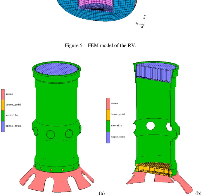
The structures investigated and for which a FEM model has been realized are the reactor vessel, with its main internals, and a detailed model of the inner structures constituted of the lower and upper grid, the inner vessel and the vessel support skirt.
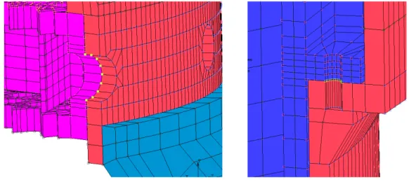
Figure 5 shows a global view of the reactor system while Figure 6 the inner vessel with the main system, support and components. Moreover Figure 6 b offers an overview of the relative position of each component and the related contact status/restraints.
The models were set up, assembled with appropriate elements, e.g. 3-D solid brick and/or shell thick elements, available in the used finite element MSC.MARC© code. The number of element for is about 70.000 for the only inner vessel model.
Figure 5 – FEM model of the RV.
(a) (b)
Figure 6 – FEM model of the inner cylindrical vessel: view (a) and vertical section (b). Anchorage
Lead Inner vessel
Diagrid
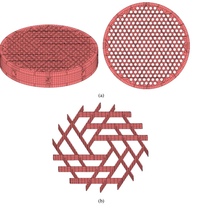
3.1.1. Lower grid
The lower grid is a 550 mm height cylindrical shell, with 3420 mm external diameter and 100 mm thickness. It was supposed to be made of austenitic stainless steel AISI 304. This component, showed in Figure 7, is enclosed by two identical cylindrical perforated plates, each one 100 mm thick. The distance between the two plates is guaranteed through an internal grid with an hexagonal geometry, as shown in Figure 7 b. On its lateral surface are obtained eight holes, four of which are used for the insertion of plugs that allow to connect the lower grid to the bottom part of the inner vessel.
(a)
(b)
3.1.2. Inner vessel and support skirt
The inner vessel is a cylindrical shell of diameter variable along the overall height. The main values of the diameter and thickness are, respectively, 3320 mm and 50 mm; the height is 9070 mm.
Figure 9 and Figure 8 show the detailed model of the overall inner vessel.
In the lower portion of the inner vessel the diameter is slightly greater than the main value to allow the insertion of the lower grid. The two components are connected by means of plugs inserted in concentric holes obtained on their lateral surface. In the middle part of this structure it can be seen a further increase in the diameter and thickness due to the presence of eight nozzles.
In this study the piping, connecting the inner vessel, through the nozzles, to the pump are not represented in order to reduce the number of the element of the overall model and subsequently reduce the computational cost of each analysis.
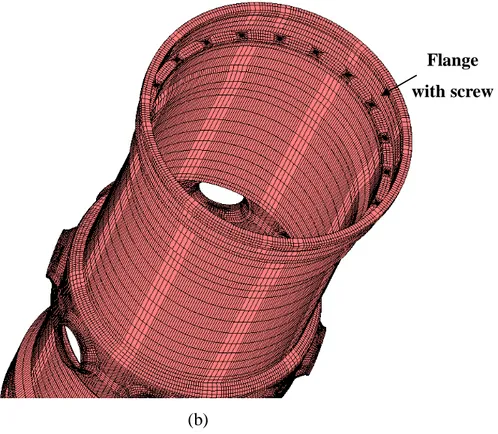
In its upper part, finally, is present an inner flange that allows to support the upper grid. The upper grid and inner vessel are linked together by means of twenty screws, as it is possible to observe in a detail of the model implemented and sown in Figure 8 a.
(a)
Nozzle
(b)
Figure 8 – Details of the FEM model of the inner vessel: bottom part with lower late and diagrid (a) and upper part with flange for the positioning of upper grid (b).
The inner vessel is linked at the bottom of the reactor vessel through the diagrid, which anchors it (in a removable way) on the inner bottom surface of the reactor vessel.
The diagrid has a truncated cone profile; the circumferential surface has several openings in order to allow the coolant lead to flow upward. Both the inner vessel and the support skirt are supposed to be made in AISI 304 steel.
3.1.3. Upper grid
The upper grid (Figure 9) is a 1000 mm high and 60 mm thick cylindrical shell, enclosed at the ends by two perforated cylindrical plates. The diameter of the holes in the upper plate is 20 mm, while the one of the holes in the lower plate is 90 mm. An inner grid separates the two plates, its geometrical shape is similar to that one of the lower grid, shown in the previous Figure 6 b.
Flange with screw
Figure 9 – Details of the implemented FEM model of the upper grid.
A middle height positioned crown surrounds the upper grid, at the base of the crown twenty holes are obtained for the insertion of the screws used for the connection of the upper grid to the inner vessel. Like the other components, also the upper grid is assumed to be made of AISI 304 steel.
4. Simulation of the dynamic transient
The performance of the safety functions should be ensured by means of appropriate design of the core and its associated systems to ensure that they are capable to withstand the robust effects of dynamic loadings on core.
To investigate the effects of core compaction phenomenon modal analysis, steady state analysis and dynamic transient analysis have been carried out. Moreover the influence of contact is considered since it (components interactions) may influence vibration and Hertz phenomena.
4.1. Initial and boundary conditions
As mentioned in the previous section, the lower grid is positioned inside the bottom part of the inner vessel and the restrains is obtained by means of plugs inserted in concentric holes located on their lateral surface. In the modelling phase, this type of connection is simply obtained “collapsing” into one single node the adjacent nodes of the two components: as an example, in Figure 10 all the joined nodes, lying in the perimeter of the connected holes and belonging to the inner vessel and the lower grid, are in yellow. The same procedure is adopted as well to represent the connection between the upper grid and the inner vessel (Figure 10).
Figure 10 – Detail of the connection between the lower and upper grid and the inner vessel.
To characterize the interaction among the reactor structures during the seismic event, surface-to-surface contact conditions have also been carried out. Among the different type of contact features
and considering the nature of stresses the components undergo, the “deformable body” contact condition was selected. Single-side contact was also assumed. To be implemented correctly, contact tables have been created representing the existing contacts at the beginning of the analysis. The minimum contact distance, defined as the distance value below which two bodies are going in contact, was assumed equal to 10-5 m.
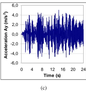
As for the dynamic loading to use as input, it is worthy to stress that it had been calculated in the preliminary activity performed in the framework of the PAR 2012. The seismic input is in fact the propagation of the synthetic earthquake motion, of 0.3g PGA, 20 s duration and 0.01 s time interval, propagated at the reactor vessel anchorage. These acceleration values are represented in the diagrams of Figure 11 [1]: in respect to the input PGA, the horizontal accelerations reduced of a 40% while the vertical component (indicated as Ay in figure) amplified along the reactor building height0f 30%. This input motion has been applied, with all the three acceleration components simultaneously, at the reactor vessel anchorage.
-2,0 -1,0 0,0 1,0 2,0 0 4 8 12 16 20 24 Time (s) Acceleration Ax (m/s 2 ) (a) -2,0 -1,0 0,0 1,0 2,0 0 4 8 12 16 20 24 Time (s) Acceleration Az (m/s 2 )
-6,0 -4,0 -2,0 0,0 2,0 4,0 6,0 0 4 8 12 16 20 24 Time (s) Acceleration Ay (m/s 2 ) (c)
Figure 11 – Accelerations Time Histories at the RV anchorage restraints.
Furthermore, because of its complexity and due to the lack of information related to the geometrical shape (design data and restraints characteristics), simulation of dynamic effects of the core with assembly interactions together was not carried out in the set up and implemented 3-dimensional models. Specifically the core region has been represented by means of its geometrical boundaries, and the fuel mass considered as lumped mass distributed on the fuel supporting plate.
To correctly simulate the link between the support skirt and the main vessel and the one between the inner vessel and the reactor cover, the applied restraints impose a zero displacement for the involved nodes.
5. Simulation of the dynamic transient
In what follows the results obtained from the analysis of steady state and dynamic transient are herein presented and discussed. They are in terms of acceleration, stress and displacement as shown in the diagrams and distribution of Figure 12 ÷Figure 11.
The steady state results, like the dynamic transient ones, allow to highlight the influence of contact force: the distribution of the Von Mises stress indicates how the contact and friction forces (performed in this study simply considering the Coulomb approach), that are responsible also of a change of the compression rigidity of structures, influence the deformation of the element cross-section and the re-distribution of the stress in the element thickness.
(a) (b)
Figure 12 – Von Mises stress without (a) and with contact and friction forces influence (b).
It is important to highlight that in this preliminary study the coupling effects between the fluid and the surrounding structures was not implemented for computational cost reasons.
represented in the following Figure 13: these values indicated that the displacement is variable along the overall structures reaching about 6 cm in the upper plate and 2 mm in the lower one (as visible in the diagram of Figure 14).
a) b)
Figure 13 –Displacement along the overall inner vessel at 4 s and 5.5 s.
a) Undeforrmed
shape deformed shape
b)
c) Figure 14 – Displacements along the overall inner vessel.
Figure 15 – Total displacement along the overall inner vessel.
The stress distribution indicated that in several part of the IC stresses overcome the yielding limit, particularly in its upper part close to the flange support and upper grid and in the annular area neighboring the nozzle penetration (Figure 17 a). This results is in agreement with what observed in terms of displacement.
In general it is possible to observe that the main body of both the lower and upper diagrid did not suffer wider plasticization, as indicated in diagrams of Figure 17 b, representing the mean value of Von Mises stresses calculated at the element centroid.
In addition another concern to face arisen investigating the nozzle-piping region that needs, for the geometry taken into account for his study, be adequately reinforced since it appears to undergo very large deformation that would unavoidably influence the normal reactor operation.
(b)
Figure 17 – Von Mises stress distribution along the inner vessel at t = 5.75 s (a) and mean value far from the nozzle area (b).
A dedicated analysis has been also carried out to investigate the influence of the contact force. The aim was to detect the motion of the bodies, apply a constraint to avoid penetration, and apply appropriate boundary conditions to simulate the frictional behaviour.
The ability to model the contact phenomena included the analysis of interference fits among components. The analysis of contact behaviour had been complex because of the requirement to accurately track the motion of multiple geometric bodies, and the motion due to the interaction of these bodies after contact occurs. In doing that a representation of the friction between bodies surfaces was also required. In addition a robust numerical procedure to simulate these complex physical problems has been implemented in Marc© code.
The results of the dynamic transient analysis are showed in the following Figure 18 and Figure 19 representing the contact forces acting at the interface between upper grid and inner vessel and lower grid inner vessel as well.
The calculated overall displacement (Figure 20) at several location of the core region confirmed that it is variable along the structures studied reaching a maximum value of about 6 cm in the upper plate, while generally far from this location its mean value is about 2-3 mm.
Figure 18 –Contact normal force at the surface between upper (green line) and bottom grid (red line) and the inner vessel.
b) Figure 19 – Overall contact force at the lower (a) and upper grid (b).
Analyzing Figure 21a and comparing it to Figure 17a it is possible to observe the influence of the contact force not only on the main body of the inner vessel, on the surface of which a much wider plasticization appears, but also on both the lower and upper diagrid.
The stresses exceeds locally the allowable one, even if representing the mean value of Von Mises stresses calculated at the element centroid seemed to guarantee the structural integrity of Internals (Figure 21 b).
As already indicated, the nozzle-piping region confirms the needs of an upgrading of the core region design, by adequately reinforcing these areas.
(b)
Figure 21 – Von Mises stress distribution along the inner vessel at t = 5.45 s (a) and mean value far from the nozzle area (b).
Finally, further improvements are needed to evaluate deeply both the collective and the specific behaviour of the FAs on the basis of results presented and discussed in this study.
6. Conclusion
In this report the results obtained from the investigation of the core compaction analysis, taking into account also the influence of contact forces, have been presented and discussed.
In performing the dynamic analyses, steady state, modal and dynamic transient, the Time History method coupled to the substructure approach, were used.
Because of the complexity of the geometry of the internals and considering the limitation imposed by the lack of information related to the geometrical shape of some of these components, of the design data and restraints characteristics, the simulation of dynamic effects on the core was performed on firstly on a 3-dimensional model of the overall reactor vessel (with reference to ALFRED reactor geometry), and subsequently on the main internal structures, such as inner vessel, upper grid, lower grid, etc..
The numerical results obtained, for the implemented models and assumption made, highlighted that the overall displacement calculated along the inner cylindrical vessel is variable: it reaches about 6 cm in the upper plate while a mean value of 2 mm far from that location. Such a type of displacement was observed also when contact features are implemented in the simulations.
The stress distribution indicated instead that in several part of the inner vessel the stresses overcome the yielding limit, particularly in its upper part close to the flange support, in the upper grid and in the annular area neighboring the nozzle penetration: these data are in agreement with what observed in terms of displacements and deformations.
In general it is possible to observe that the main body of both the lower and upper diagrid did not suffer wider plasticization, as indicated by the mean value of Von Mises stresses calculated at the element centroid.
The influence of the contact and friction forces have been highlighted not only on the main body of the inner vessel, on which surface a much wider plasticization appears, but also on both the lower and upper diagrid. The stresses exceeds locally, but in a much wide area of the inner vessel components (in respect to the case in which contact is not taken into account) the allowable one, even if representing the mean value of Von Mises stress, also in this case, seemed to guarantee the structural integrity of Internals.
Vibration phenomena have been also observed in performing the dynamic analysis, the input ATHs of which had been calculated in the activity performed in the framework of the PAR 2012.
Finally, these data would be used to analyse the fuel assembly and sub-assembly element in order to determine the extent of deformation and the level of compaction caused by such a type of dynamic load on the fuel assembly and thus on the core.
It is important to note that further developments are necessary to evaluate more in depth the deformation of assemblies and subassemblies as well as of the element/pad cross-section also in consideration of the friction and contact forces arisen at the interface between the internal components. Another aspect to be investigated deeply is the influence of the fluid-structure interaction.
In conclusion an experimental campaign is suggested in order to validate the methodological approach and model developed in order to develop a benchmark which will play an important role in supporting the core design.
References
[1] G. Forasassi, R. Lo Frano, G. Pugliese. Core compaction phenomenon: methodological approach. DICI, University of Pisa, 2013.
[2] R. Lo Frano, G. Pugliese, G. Grasso, G. Forasassi, Preliminary evaluation of core compaction phenomenon: methodological approach, Proceedings of the ASME 2014 Small Modular Reactors Symposium, Washington, DC, USA, April 15-17, 2014.
[3] K. Tsukimori, H. Negishi, Development of ‘pad element’ for detailed core deformation analyses and its verification, Nuclear Engineering and Design, 213, 141–156, 2002.
[4] A. S. Chuang, H. Jones. Seismic design of GCFR core support system. Genaral Atomic Company, 1979.
[5] H. Zehlein. Coupled problems in transient fluid and structural dynamics in nuclear engineering. Institut fűr Reaktorentwicklung, Gesellschaft fiir Kernforschung mbH, 1977. [6] J. Buongiorno, B.D. Hawkes. Seismic analysis of heavy-liquid-metal-cooled reactor vessels.
Idaho National Engineering and Environmental Laboratory, Nuclear Engineering Department, 2003.
[7] Kazuyuki Tsukimori, Hitoshi Negishi. Development of ‘Pad Element’ for detailed core deformation analyses and its verification. Structural Mechanics Research Group, O-arai Engineering Center, Japan Nuclear Cycle Development Institute (JNC), 2001.
[8] P. Chellapandi, S.C. Chetal, Baldev Raj. Numerical simulation of fluid–structure interaction dynamics under seismic loadings between main and safety vessels in a sodium fast reactor. Indira Gandhi Centre for Atomic Research, 2012.
[9] F. Zylbersztejn. Study of the core compaction effects and its monitoring in sodium cooled fast reactors. CEA, DEN, Cadarache, DER/SPEx/LDCI, 2012.