Alma Mater Studiorum – Università di Bologna
DOTTORATO DI RICERCA IN
MECCANICA DEI MATERIALI
E PROCESSI TECNOLOGICI
XXI Ciclo
SOME ISSUES CONCERNING
THE DYNAMIC RESPONSE AND DAMAGE
OF COMPOSITE LAMINATES
SUBJECTED TO LOW VELOCITY IMPACT
Candidato: DANIELE GHELLI
Coordinatore: Relatore:
prof. ing. TULLIO TROMBETTI
ing. GIANGIACOMO MINAK
Settore scientifico-disciplinare di afferenza:
ING-IND/14
PROGETTAZIONE MECCANICA
E COSTRUZIONE DI MACCHINE
Contents
Preface V
1 Main features of the finite element program used for numerical analysis 1
References for chapter 1 7
2 Discussion on the analogy between low velocity impact and quasi-static indentation 9
2.1 Introduction 9
2.2 Experimental procedure 12
2.2.1 Low velocity impact tests 12
2.2.2 Quasi-static indentation tests 13
2.2.3 Specimen inspection 14
2.3 Numerical modelling 14
2.4 Results of the experimental tests 15
2.5 Results of the numerical analysis 21
2.5.1 Quasi-static indentation 21
2.5.2 Low velocity impact 24
2.6 Comparison between impact and indentation 26
2.7 Conclusions 29
References for chapter 2 30
3 Effect of different specimen diameter and boundary conditions on the impact behaviour of
circular laminates 33 3.1 Introduction 33 3.2 Experimental testing 34 3.3 Numerical modelling 36 3.4 Results 38 3.5 Discussion 41 3.6 Conclusions 45
References for chapter 3 46
4 Impact and compression after impact testing according to two different ASTM standards 49
4.1 Introduction 49
4.2 Experimental method 50
4.2.2 Impact tests 51
4.2.3 CAI tests 51
4.3 Numerical analysis 52
4.4 Results and discussion 53
4.4.1 Impact tests 53
4.4.2 CAI tests 57
4.5 Conclusions 66
References for chapter 4 67
5 Influence of in-plane loading on the impact response of laminated plates 69
5.1 Introduction 69
5.2 Main features of the numerical model 71
5.2.1 Choice of the case studies 71
5.3 Tension preload 73 5.3.1 Case studies 73 5.3.2 Results 74 5.3.3 Discussion 75 5.4 Compression preload 81 5.4.1 Case studies 81 5.4.2 Results 82 5.4.3 Discussion 84 5.5 Conclusions 88
References for chapter 5 88
Preface
Laminated composite materials have several advantages over metals: first of all a lower stiffness-to-weight and strength-to-weight ratio, as well as the possibility for the designer to vary their structural properties within wide ranges and tailor them to meet the requirements of specific applications. These advantages led to an extensive use of composite materials for structural components in a number of industrial products, ranging from primary load-bearing members of airplanes to civil constructions and sporting goods.
Laminated composites, however, are usually brittle materials. As a consequence, they do not exhibit phenomena of energy absorption and dissipation through plastic strain which in many cases enable metals to maintain their structural integrity after undergoing high stresses, such as those arising from impulsive loads. For this reason energy absorption in composites usually takes place through material damage. In addition, the internal structure of laminates, which commonly consist of several plies stacked together to form a single body, facilitates the creation of embedded flaws, named delaminations, between adjacent plies because of the poor strength of their interface. This kind of damage can be undetectable by visual inspection, but at the same time can lower the resistance of a laminate significantly.
Given that impacts of a variety of objects, from tools to stones or hail in the case of aircrafts, cannot be avoided during the life of a component, the susceptibility of composites to impact damage has justified an extensive research effort during the last four decades, aimed at understanding both the failure mechanisms and the influence of damage on the mechanical properties of the material. A great interest still exists in this topic, because while there is a substantial agreement on certain issues other problems cannot be considered completely solved.
Research studies resulted in the publication of several hundreds of articles: at present the vastness of the subject and the complexity of the questions that have arisen prevent a comprehensive investigation of the topic of impact on composite materials. In view of this, it was chosen to treat in detail only a few particular aspects, whose common features are on the one hand the importance, both theoretical and practical, on the other hand the relatively limited attention received so far. All of these aspects refer to low velocity impact.
Chapter 2 deals with the comparison between the effects of low velocity impact and of quasi-static indentation. This issue has considerable practical interest because carrying out a quasi-static experimental test is much easier than performing a dynamic test: therefore if the
mechanical response of a laminate, especially as regards damage, to indentation was found to be analogous to the response to impact, the examination of impact behaviour would be greatly simplified. A few research papers are available which do not seem to provide a definitive answer, also because in most of them the assessment of the analogy between impact and indentation is not the main object. A direct comparison, by means of both experimental testing and numerical analysis, is presented here, which aims at establishing to what extent that analogy can be considered valid.
Chapter 3 discusses the effect of different dimensions and boundary conditions of the specimens on the experimentally recorded low velocity impact behaviour and damage. This problem arises when experimental results obtained in different test configurations are to be compared, as well as when one attempts to use results from laboratory tests in the design of real structures. Interesting relationships of the extent of damage with two significant impact parameters, that are the absorbed energy and the peak contact force, are commented on and shown to be independent of the geometry and boundary conditions with reasonable approximation. The possibility of predicting, by means of a simplified numerical analysis, whether delaminations are induced or not during a specific impact event is also discussed.
In chapter 4 the results of impact and compression after impact tests, carried out according to two different standards, are presented. It is known that the strength reduction caused by low velocity impact is usually the largest when the damaged laminate is loaded in compression. Therefore the study of the compression behaviour of composites after impact has received considerable attention. In most of the numerous articles concerned with this topic, however, the test apparatus is designed in such a way as to avoid global buckling of the specimen, in order to obtained strength values which can be attributed to the material itself, regardless of the specimen geometry. The present study focuses on test conditions where instability is not prevented. With the aid of a numerical analysis of the postbuckling regime, some aspects of the interaction between global buckling of the laminate, local buckling of the delaminated region and impact damage are highlighted.
Chapter 5 focuses on another issue that has received limited attention: the influence of pre-existing membrane loading on the impact response and damage of laminates. The significance of this problem is obvious since hardly ever is a structure completely unloaded when is subjected to an impact during service or maintenance; only a laboratory apparatus can ensure that a specimen undergoes an impact being free of in-plane stresses. The available literature provides quite limited information, mainly on tests carried out in a small number of special cases, and appears far from giving conclusive answers on how a preload can affect the material failures. A more comprehensive investigation is presented here, based on a number of numerical simulations, which is thought to be useful in providing general guidelines, especially on how the influence of preload changes depending on the test conditions. The results provide a better explanation of experimental findings reported in the literature.
behaviour of composite materials is not sufficiently established for a research activity to be done without experimental testing, a sound theoretical basis also appears necessary to interpret the test results correctly. This provided the motivation for developing a finite element program which has been employed for both static and dynamic calculations, since the applicability of analytical or semi-analytical models to impact problems is limited to a few special cases. The main features of the program are described in the first chapter.
CHAPTER 1
Main features of the finite element program
used for numerical analysis
In the study of laminated plates or shells, analytical solutions are available only for a limited number of special problems, even in the case of a linear static analysis which is by far the simplest one. When impact problems are dealt with, closed-form solutions can be obtained only for extremely simple models where, in addition, suitable assumptions are introduced which lead to linearized equations to be solved. In impact phenomena, however, several nonlinear effects are present: first of all contact between impactor and target, as well as large displacements and nonlinear constitutive equations in many cases. Accounting for such effects, even in a single-degree-of-freedom model, requires some form of numerical solution procedure to be employed [1].
This provided the motivation for an extensive use of numerical computation in all of the specific topics which are treated in chapters 2-5. Simplified models with a very small number of degrees of freedom can be helpful for gaining a general understanding of impact phenomena, and establishing some overall guidelines regarding the influence of the main impact parameters. However for a more detailed study, especially when a reliable evaluation of the stress field in an impacted laminate is needed, a different approach appeared necessary. To this end the finite element method was chosen.
The development of an in-house program was preferred to the use of a commercial code for several reasons. First of all, a general-purpose package has many features which one never employs when rather specific analyses, such as impact on composites in the present case, are to be carried out. On the other hand, for a specific task several peculiar capabilities are often required, for example regarding control of the finite element formulation or the solution method, or suitable post-processing techniques, which are often difficult to find or to implement or not available at all in commercial programs. Most importantly, the first concern for the aims of the present thesis was a complete control on the capabilities and limits of the numerical model and the results, rather than the use of very sophisticated models which would be so difficult to verify and validate that one would end up by treating them as black boxes.
A description of the features of the program can be found in what follows. Its reliability was checked by a large number of tests, some of which are reported in [2].
The program was first conceived to perform a numerical analysis of the transient response of a laminated plate or shell. Explicit time integration is carried out by means of the central difference method; geometrical nonlinearity is implemented according to the total lagrangian (TL) formulation [3]. The reasons that justify these choices are explained in the following.
The starting point of the numerical model is the principle of virtual displacements, which can be expressed in the general form valid for a three-dimensional problem [3]:
( )
( )
[
−]
+( )
= =∫
∫
∂ 0 0 0 0 0 0 0 V i i V i i i ve b t u t u dV p t u dS W ρ δ δ δ &&( )
vi V AB AB t E dV W s δ = δ =∫
0 0 (1)where sAB is the second Piola-Kirchhoff stress tensor, EAB is the Lagrangian finite strain tensor
[4], are the body forces per unit mass, are the surface loads per unit area, ui are
displacement components along the three cartesian axes xi. The summation convention has been
used in (1) for subscripts A, B and i. The superscript 0 means that the material volume V0 and its boundary , as well as external forces, stresses and strains, refer to the initial configuration of the body which is taken as the reference configuration, according to the TL approach [3]. Stress and force values at time t appear in (1) because the central difference method requires solving the equilibrium equation at time t to find the solution at time t + h, h being the time integration step [3]. This leads to great simplifications in the treatment of nonlinear phenomena, because the system of equations to be solved at each time step is linear; thus no incremental decomposition of stresses and strains is needed, and iterative solution within each time step is not necessary [3]. On the other hand, the time step must be lower than a critical value to ensure stability of the algorithm [3].
0 i b 0 i p 0 V ∂
Since the TL and updated lagrangian (UL) formulations are equivalent in the description of nonlinear phenomena, the choice between them is driven by computational efficiency considerations, particularly regarding calculation of strain-displacement matrices [3]. In explicit dynamic analysis the same kind of matrices must be used for both formulations; the UL requires them to be recalculated at each time step, while in the TL they refer to the initial configuration, so they remain the same during the whole time interval to be analysed. For this reason the TL formulation has been adopted here.
The general equation (1) can be rewritten in the suitable form for plate analysis by introducing the kinematic assumptions of a plate theory. For the Reissner-Mindlin plate model, used in the present formulation, they are [1]:
(
x y z)
u( )
x y z( )
x y u , , = 0 , + ϑy ,(
x y z)
v( )
x y z( )
x y v , , = 0 , − ϑx ,(
x y z)
w(
x y w , , = 0 ,)
(2)where the z direction is perpendicular to the middle plane; u, v, w are displacements of any point in the x, y, z direction respectively, while u0, v0, w0 are the displacements of the middle plane; ϑx
and ϑy are the section rotations about the x and y axes respectively. To obtain a two-dimensional
problem, further simplification is necessary concerning geometrical nonlinearity. Here it is assumed that the only significant nonlinear terms in finite strain tensor E are those due to w0
displacement appearing in the in-plane strains; this hypothesis corresponds to the Von Kármán’s model for plates subjected to large deflections [5]. Therefore, using subscripts x, y and z instead of 1, 2 and 3: x z x w x u Ex y ∂ ∂ + ⎟ ⎠ ⎞ ⎜ ⎝ ⎛ ∂ ∂ + ∂ ∂ = ϑ 2 0 0 2 1 y z y w y v E x y ∂ ∂ − ⎟⎟ ⎠ ⎞ ⎜⎜ ⎝ ⎛ ∂ ∂ + ∂ ∂ = ϑ 2 0 0 2 1 ⎟⎟ ⎠ ⎞ ⎜⎜ ⎝ ⎛ ∂ ∂ − ∂ ∂ + ∂ ∂ ∂ ∂ + ⎟⎟ ⎠ ⎞ ⎜⎜ ⎝ ⎛ ∂ ∂ + ∂ ∂ = x y z y w x w x v y u E y x xy ϑ ϑ 2 2 1 2 1 0 0 0 0 ⎟ ⎠ ⎞ ⎜ ⎝ ⎛ + ∂ ∂ = y xz x w E 0 ϑ 2 1 ⎟⎟ ⎠ ⎞ ⎜⎜ ⎝ ⎛ − ∂ ∂ = x yz y w E 0 ϑ 2 1 (3)
The assumptions in (2) and (3) limit the applicability of the present model to cases where the strains are small, even if displacements and rotations can be relatively large. With all these assumptions the internal virtual work in (1) becomes, after some manipulation:
( )
(
)
(
( ))
[
]
∫
∫
+ + + ∂ ∂ = 0 0 0 0 ~ A T A T T T vi dA dA W δEml N δc M δEs Q δ w0N w0 δ (4)c, E(s), and E(m)l being the vectors of curvatures, out-of-plane shear strains, derivatives of w0 and linear part of middle plane strains respectively:
0 w ∂ ⎥ ⎥ ⎥ ⎥ ⎥ ⎥ ⎥ ⎦ ⎤ ⎢ ⎢ ⎢ ⎢ ⎢ ⎢ ⎢ ⎣ ⎡ ∂ ∂ − ∂ ∂ ∂ ∂ − ∂ ∂ = x y y x x y x y ϑ ϑ ϑ ϑ c ; ( ) ⎥ ⎦ ⎤ ⎢ ⎣ ⎡ = yz xz E E 2 2 s E
( ) ⎥ ⎥ ⎥ ⎥ ⎥ ⎥ ⎥ ⎦ ⎤ ⎢ ⎢ ⎢ ⎢ ⎢ ⎢ ⎢ ⎣ ⎡ ∂ ∂ + ∂ ∂ ∂ ∂∂ ∂ = x v y u y vx u 0 0 0 0 l m E ; ⎥ ⎥ ⎥ ⎥ ⎦ ⎤ ⎢ ⎢ ⎢ ⎢ ⎣ ⎡ ∂ ∂∂ ∂ = ∂ y wx w 0 0 0 w
N, M and Q are the vectors of membrane forces, moments and shear forces per unit length; N~ is a matrix containing the membrane forces:
⎥ ⎥ ⎥ ⎦ ⎤ ⎢ ⎢ ⎢ ⎣ ⎡ = xy y x N N N N ; ; ; ⎥ ⎥ ⎥ ⎦ ⎤ ⎢ ⎢ ⎢ ⎣ ⎡ = xy y x M M M M ⎥ ⎦ ⎤ ⎢ ⎣ ⎡ = y x Q Q Q ⎥ ⎦ ⎤ ⎢ ⎣ ⎡ = y xy xy x N N N N N~
The integrals in (4) are performed over the middle surface A0 of the plate, because to obtain (4) from (1) integration along z is carried out.
In the most general case of asymmetric laminate, the internal force and moment resultants per unit length are related to the strains by the constitutive equations [1]:
( ) Bc E A N = m + ( ) Dc E B M = m + ( ) ( )s Es D Q = (5)
where the constitutive matrices of the laminate are:
( )
(
)
∑
= − − = n k k k k z z 1 1 m D A ;∑
( ) = − − = n k k k k z z 1 2 1 2 2 m D B ( )∑
= − − = n k k k k z z 1 3 1 3 3 m D D ; ( )∑
( )(
)
= − − = n k k k k z z 1 1 1 s s D D χ ( )mDk and are the in-plane and shear constitutive matrices of the kth ply respectively; zk and
zk-1 are the z coordinates (with respect to the middle plane) of the upper and lower surface of the
kth ply; n is the total number of plies; χ is the shear correction factor. In (5) E(m) contains also the nonlinear terms of middle plane strains. In general an orthotropic material behaviour is considered, so that isotropic behaviour can also be modelled as a special case.
( )s
Dk
The kinematic assumptions (2) lead also to the following expression of the external work:
∫
∫
∫
+ − = ∂ 0 0 0 0 0 0 A T A T A T ve dA dl dA W V f V f0 V I0V l 0 s δ δ && δ δ (6)0 s
f and being the surface and boundary load vectors, I0 being the inertia matrix and V being the degrees of freedom vector:
0 l f
[
x y]
T u v w ϑ ϑ 0 0 0 = VEquating (4) and (6) and introducing the nodal interpolation of degrees of freedom:
Δ H V= ( ) B( )Δ Eml = ml ; c = B( )f Δ ; E( )s = B( )sΔ ; w B( )mnlΔ 0 = ∂
the principle of virtual displacements (1) can be rewritten in the form: = − +
∫
∫
∫
∂ Δ H I H Δ f H Δ f H Δ 0 0 l 0 s && 0 0 0 0 0 0 A T T A T T A T T dA δ dl δ dA δ ( )( )
( )
( )( )
( )[
B N B M B Q]
Δ(
B( ))
NB( ) Δ Δ ml f s mnl mnl∫
∫
+ + + = 0 0 0 0 ~ A T T A T T T T dA δ dA δwhere Δ is the vector of nodal degrees of freedom, containing as many subvectors analogous to V as the nodes of the finite element model are. Finally, applying the principle of virtual displacements, the dynamic equilibrium equation for the discretized plate is obtained:
Δ K F Δ M R R 0 l nl l 0 s + − && = + (7)
Here and are the surface and boundary external load vectors, M is the mass matrix, Fl is the linear part of the internal forces vector and Knl is the nonlinear (geometrical) stiffness matrix. , , Fl, Δ and refer to time t.
0 s R 0 l R 0 s R 0 l R Δ&&
Instead of calculating the B(s) matrix according to the standard procedure of isoparametric elements, a particular formulation proposed by Hughes has been adopted, in which the out-of-plane shear strains are interpolated separately rather than deduced from nodal displacements and rotations. This element ensures low shear locking without the need for reduced or selective integration, thus without rank reduction [6]. Three- and four-node elements are available [7].
The in-plane stiffness has been added to flexural behaviour of Hughes’ element, following the usual isoparametric formulation; then a flat shell element has been implemented with a simple coordinates change by means of rotation matrices, thus allowing to locate the finite element in a three-dimensional frame. Obviously the third rotation ϑz must be added in this case.
By expressing velocities and accelerations in terms of the nodal degrees of freedom, according to the central difference method [3]:
( )
(
)
(
)
h h t h t t 2 − − + =Δ Δ Δ&( )
(
)
2 2( )
(
)
h h t t h t t =Δ + − Δ +Δ − Δ&& (8)a system of linear algebraic equations can be derived from (7):
(
)
( )
( )
( )
(
t h)
h t h t t h t h + = − + − Δ − M Δ M F R Δ M 0 2 2 2 2 (9)where is the external load vector and is the internal load vector. The equations, to be solved for the unknowns Δ(t + h), are uncoupled if the mass matrix is diagonal; thus a lumped matrix has been chosen. To ensure that the mass matrix remains diagonal in every coordinate system, the same mass has been attributed to all the nodal displacements, and all the three nodal rotations have been assigned the same rotary inertia.
0 l 0 s 0 R R R = + F=Fl +KnlΔ
In order to extend the capabilities of the program and make it possible to perform also static analyses, a dynamic relaxation [8] algorithm has been subsequently implemented. With this technique, and taking advantage of the explicit integration scheme, static computations in presence of strongly nonlinear phenomena, such as elastic instability, can be carried out in a robust and efficient way. As known, the dynamic relaxation technique consists in introducing an artificial viscous damping action, thus equation (7) becomes:
Δ K F Δ M Δ C R R 0 l nl l 0 s + − & − && = + (10)
If constant external loads are applied, the transient solution of the system (10) converges to its steady state part, which satisfies the equilibrium equations:
Δ K F R R 0 l nl l 0 s + = +
Since in this case the aim of the explicit analysis is to reach a static solution, which depends only on the stiffness properties of the structure contained in the internal load vector F on the right hand side, while the transient part of the solution is not of interest, the mass matrix M need not reproduce the real inertial properties of the structure. In the present study, during the dynamic relaxation calculations the elements of M were given fictitious values, obtained with a procedure based upon Gershgorin’s circle theorem which improves the computational efficiency of the algorithm [8].
When the damping actions are present, by substituting expressions (8) in the equation of motion (10) a new system of linear algebraic equations is derived, which replaces (9):
(
)
( )
( )
( )
(
t h)
h h t h t t h t h h ⎟⎟⎠ − ⎞ ⎜⎜ ⎝ ⎛ − + + − = + ⎟⎟ ⎠ ⎞ ⎜⎜ ⎝ ⎛ + C Δ R F MΔ C M Δ M 2 2 2 2 2 2 (11)To preserve the simplicity of uncoupled equations in the system (11), the damping matrix C was set proportional to M, so that both matrices were diagonal; the ratio between the elements of C and the elements of M was adjusted in order to approximate the condition of critical damping for the first (fictitious) vibration mode, because in this way the number of iterations required for convergence is the lowest [8].
A simplified contact model has been implemented to allow a dynamic analysis of impact of external bodies on the plate or shell. The impactor is considered a rigid body in translational motion (thus treated as a heavy material point), and the force taking place between impactor and laminate is concentrated on one node. The indentation is determined as the difference between the displacement of the impactor and that of the node on which contact is intended to occur; the contact force P is related to the indentation α by the Hertz’s generalized contact law [1]:
n C
P = α (12)
At present, contact and large deflections are the only nonlinear phenomena accounted for in the numerical model. In particular, no post-failure degradation criterion of the material properties has been implemented, so that the elastic constants do not change during the simulations even if failure is predicted. This simplifying assumption makes it possible to obtain reliable results as long as the actual material damage is limited. Given the absence of a damage model, for the sake of simplicity the same contact law (12) is employed for both loading and unloading phase of contact.
Although the central difference method usually requires small time steps because the algorithm is conditionally stable [3], this scheme has been preferred because it lets the program open to a number of future improvements, including the implementation of damage models of the material. Indeed the explicit integration makes it possible to derive a linear system of algebraic equations (see (9) and (11)) whatever the nonlinear effect one may introduce. Otherwise an iterative solution process would be needed within each time step, which would make the computation extremely expensive. In addition, the choice of a lumped mass matrix, which can always be maintained regardless of the other features of the model, results in a system of decoupled equations, thus the necessity of implementing suitable solution algorithms is avoided.
2. Ghelli D. Dynamic numerical analysis of composite plates and shells with geometrical nonlinearity. In: Proceedings of the ANASS 2007 Special Workshop, Sorić J, Gruttmann F,
Wagner W, editors, p. 161-168. Zagreb (HR): Croatian Society of Mechanics, 2007. 3. Bathe KJ. Finite element procedures in engineering analysis. Englewood Cliffs, New
Jersey: Prentice-Hall, 1982.
4. Mase GT, Mase GE. Continuum mechanics for engineers, 2nd ed. Boca Raton, Florida: CRC Press, 1999.
5. Timoshenko SP, Woinowsky-Krieger S. Theory of plates and shells, 2nd ed. Singapore: McGraw-Hill, 1959.
6. Hughes TJR, Tezduyar TE. Finite elements based upon Mindlin plate theory with particular reference to the four-node bilinear isoparametric element. J Appl Mech-T
ASME 1981;48(3):587-596.
7. Hughes TJR. The finite element method - linear static and dynamic finite element analysis.
Englewood Cliffs, New Jersey: Prentice-Hall, 1987.
8. Underwood P. Dynamic relaxation. In: Computational methods for transient analysis,
CHAPTER 2
Discussion on the analogy
between low velocity impact and quasi-static indentation
*2.1. Introduction
Carbon Fibre Reinforced Polymers (CFRP) are widely used in applications requiring high specific strength and stiffness. Well known problems arise, however, when the resistance of this kind of material to foreign object impact is considered. The essentially brittle mechanical behaviour of CFRPs makes them vulnerable even to low velocity and low energy impact [1-4].
Impacts are usually classified according to initial velocity, because collisions at different velocities can lead to different dynamic responses and damage in the target. Dropping a tool is considered an example of what is called a “low velocity” impact, while, for instance, small stones striking an airplane during takeoff are said to cause a “high velocity” impact [4]. A more rigorous definition of these velocity fields is, however, required prior to investigation of different phenomena taking place in either field.
At least two definitions of “low velocity” impact can be found in the literature [5]. The one proposed by Robinson and Davies [6] and adopted by Abrate [4] is based on the propagation of elastic waves through the thickness of the impacted laminate. When the ratio between initial velocity and phase velocity is smaller than the strain which causes failure in the thickness direction, the role played by this kind of wave is considered negligible and impact velocity is said to be “low”. This defines a low velocity collision as one in which possible damage is caused by overall deformation of the laminate, thought of as a two-dimensional solid, rather than by local compression of the material at the impact point, which should be treated as a three-dimensional phenomenon.
Another definition is proposed by Sjöblom et al. [7]: “by low velocity we mean an impact velocity low enough to justify a static analysis of the response of the structure”. Hence a collision should be said to take place at low velocity if the contact duration is much greater than the time required for flexural elastic waves to reach the boundary and be reflected back, as pointed out in [8-10]. Strain rate effects on material behaviour must also be negligible [7]; this
* A revised version of this study has been accepted for publication as Ghelli D, Minak G. Comparison between low
condition is met by many classes of polymer matrix composites, but some exceptions, e. g. polyester-glass, are known [4, 10].
The two definitions are quite different. According to the first one, the transition velocity between the “low” and “high” fields depends on laminate material properties only (typical values are 10 ÷ 20 m/s [6]); according to the second one, it also depends on the dimensions and boundary conditions of the laminate and on the impactor mass, ranging from tens of m/s to cm/s [7].
Comparisons between low and high velocity impacts, in the sense of the first definition, show dissimilar dynamic response and damage [4, 6, 11] which call for high velocity impact to be considered as a separate problem [7]. On the other hand, experimental evidence exists that damage caused by low velocity impact and quasi-static indentation is similar, if not equivalent [7, 9, 11-16]. An undoubted analogy would be interesting for research purposes, since both numerical modelling and experimental testing are much simpler for a static problem than for a dynamic one [10, 14].
For this reason several available studies concern the mechanical behaviour of composite laminates subjected to quasi-static indentation, for instance [8, 16-19]. The most common justification for this choice is based upon the same arguments used by Sjöblom et al. [7] to introduce their definition of low-velocity impact: when certain conditions are met, dynamic effects are thought to be negligible. Therefore, from the above considerations about which velocity can be named “low”, one may conclude that both the reported definitions should be satisfied to attempt a comparison between quasi-static indentation and impact.
Some researchers carry out such a comparison in order to establish to what extent the resulting damage is similar. In [7] force-displacement diagrams are presented that show quite good agreement between quasi-static and dynamic tests; the damage in the laminate section also appears very similar. In [10] an energy balance approach is employed to relate impact energy and contact force and is verified experimentally. This model is based on the hypothesis that all the kinetic energy of the impactor is converted in work done on the specimen (measurable as the area enclosed by the load-displacement curve). The relationship based upon data obtained in indentation tests can also be applied to low velocity impact with good accuracy, except for the case of polyester-glass composites which exhibit rate-dependent constitutive behaviour. In [11] the difference in the delamination area for indented and impacted specimens is within the scatter of experimental data; permanent indentation, however, seems larger in quasi-static tests (the total work done during the loading phase of indentation/impact being the same). Elber [12] concludes that a static analysis can be used to characterize the impact resistance of a material; he remarks, however, that slightly more fibre damage and less extensive delamination is observed in the impacted specimens than in the indented ones. In [13] the relationship between delamination area and maximum contact force is examined; the results for indentation and impact are again identical, and also a force threshold value necessary to propagate delamination
is the same in both cases. Another comparison can be found in [14], where the authors state that static tests can be used in place of impact tests to characterize the low velocity impact response of a material, as regards contact force values and extent of delamination. Nevertheless, a diagram is reported where the experimental relationship between impact energy and maximum contact force is not the same for the two cases. In [15] empirical relationships are established between imparted energy and dent depth induced on laminates, with similar results for impact and quasi-static indentation. [9] and [16] also present similar force-displacement curves. On the other hand, numerical simulations of the dynamic behaviour of composite laminates subjected to impact show that the main features of the transient response (contact duration, maximum contact force, maximum plate deflection, maximum stresses) change when the impactor mass and velocity are modified, initial energy remaining constant [20]. This appears to be in contrast with the results reported in [6], indicating that energy is the only significant parameter of a low velocity impact.
The above observations suggest that, even if several research results seem to support the equivalence between quasi-static indentation and low velocity impact, some evidence exists that this equivalence is not always valid, and in any case it is not fully understood. Therefore further experimental testing appears necessary to provide insight into this important topic, partly because only a few recent papers specifically deal with this subject.
The present study describes the outcome of a comparison between the effects of impact and indentation on CFRP quasi-isotropic laminated plates. Both types of experimental test were performed in the same conditions; the impact velocity ranged from 3 to 5 m/s, while the energy varied from 6 to 18 J approximately. Two specimen dimensions and two boundary conditions were considered. The analysis of the experimental results was completed with a finite element numerical simulation. The specimens were inspected after testing, to assess the types and extent of damage, mainly by visual observation, but also by optical microscope and Scanning Electron Microscope (SEM).
The comparison between quasi-static and dynamic tests showed that the induced damage is qualitatively similar as regards the types of failure observed. Experimental and numerical results made it possible to recognize three characteristic contact force thresholds related to the main steps in the progression of damage which are equal in the two types of tests. The energy absorbed during impact and indentation was found to be the same. On the other hand a larger delaminated area was recorded in the quasi-static case, while evidence existed that in impact tests a more severe damage was produced, probably in the form of more significant localized fibre fracture near the impact point.
2.2. Experimental procedure
The specimens tested in this study were 16 ply quasi-isotropic plane laminates with stacking sequence [02/902/45/-45/45/-45]S, made of T300 carbon fibre-epoxy resin matrix prepregs.
Rectangular plates measuring 247 by 250 mm were obtained by curing in an autoclave. The specimen thickness was 2.7 ± 0.05 mm; the average density of the material was 1490 ± 10 kg/m3; the values of the in-plane elastic moduli and strengths supplied by the manufacturer are reported in table 1.
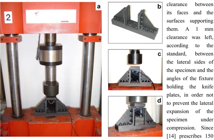
2.2.1. Low velocity impact tests
Low velocity impact tests were performed by means of a drop-weight machine (see figure 1). The impactor mass was 1.22 ± 0.01 kg; three different drop heights of 0.5, 1 and 1.5 m, corresponding to impact velocities of 3, 4 and 5 m/s approximately, and nominal impact energies of 6, 12 and 18 J, were chosen. As will be shown later, these energy levels did not cause penetration of the specimens.
Table 1 – Mechanical properties of the
single ply of the laminates tested.
The laminates were placed in a clamping fixture which consisted of two steel rings fastened to a cylindrical base, so that the geometry of a circular plate was reproduced; impact occurred exactly at its centre. Two pairs of rings of 200 and 76 mm internal diameter, respectively, were used
to test the impact response of specimens of different sizes (see figures 1c and 1d); the second diameter was chosen according to [21].
Elastic constants E1 100 GPa E2 11 GPa G12 4.2 GPa ν12 0.28 In-plane strengths Xt 1270 MPa Xc 1130 MPa Yt 30 MPa Yc 141 MPa S 63 MPa
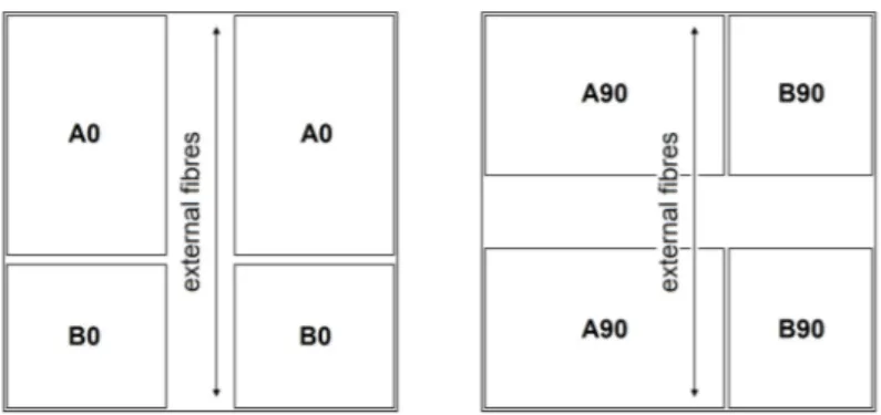
When a 200 mm diameter circular plate was simulated, the original 247 by 250 mm laminates were placed on the suitable clamping fixture; after impact, four smaller square specimens of 100 mm per side were obtained by cutting the original laminates (excluding two perpendicular 50 mm wide strips, centred on the median axes, containing the damaged zone) and were employed with the smaller rings for impact tests on 76 mm diameter plates. As explained in section 2.4, the delaminated area created by impact had an elongated shape; its largest extent was approximately 100 by 25 mm. The width of the central strips was much larger than the maximum delamination width, thus ensuring that the smaller specimens did not have any pre-existing damage before testing.
Two different boundary conditions were studied: full clamp and simple support. The first condition was accomplished by clamping the laminates between the two steel rings by four bolts; the second one was reproduced by simply placing the laminates on one ring (which was, obviously, fixed to the base) without using the second ring. It should be noted that the first arrangement was intended to prevent any motion of the plate boundary, both in-plane and
out-of-plane, while the central circular region was completely free to move; in the second condition the in-plane motion of any point of the plate was free, upward and downward motion was allowed in the region bounded by the inner ring diameter, while only upward displacement was possible outside this region. Two (in the case of larger laminates) or three (in the case of smaller laminates) tests were performed for each combination of specimen diameter, constraint condition and drop height.
Impact occurred exactly at the centre between the laminate and the hemispherical head (12.7 mm diameter) of a piezoelectric load cell attached to the impactor, which measured the contact force history (see figure 1b). The impactor fall and rebound velocity was calculated from the signal of a laser device placed 41 mm above the laminate upper surface. Both load cell and laser signals were acquired at 100 kHz sampling frequency, without any filtering in the measurement chain. An electromagnetic braking system stopped the impactor after rebound, preventing repeated strikes on the
target. Further details on the impact facility can be found in [22].
Figure 1 – Drop-weight impact tester. a) Overall view. b)
Impactor; the piezoelectric load cell with hemispherical head is visible in the lowest part of the image, in central position. c) Clamping fixture with impactor, laser sensors
and 200 mm diameter rings. d) Clamping fixture with impactor, laser sensors and 76 mm diameter rings.
The contact force signal was used to obtain the impactor displacement as a function of time by the second Newton law, as indicated in ASTM D7136M - 05 [23]: double numerical integration was performed with the initial conditions given by the laser sensor.
2.2.2. Quasi-static indentation tests
An Instron 8033 servo-hydraulic machine was used for quasi-static indentation tests, where the contact force was applied gradually rather than by means of a collision. The laminates were held by the same fixture used on the drop-weight rig, creating identical boundary conditions; to also ensure the same contact behaviour, the head of the impactor load cell was chosen as the indentor. The experiments were performed in displacement control, moving the indentor
The test plan of the quasi-static experiments was analogous to what is explained above for the dynamic ones: namely, all of the four combinations of specimen diameter and boundary conditions were covered with a similar number of tests. For each configuration, several values were chosen for the maximum displacement to be imparted to the indentor; these values were approximately within the range of maximum impactor displacements calculated for the impact tests.
2.2.3. Specimen inspection
After testing, all the specimens were first examined by visual inspection to assess the damage visible by the naked eye. In some laminates the central zone (near the impact or indentation point) was cut and incorporated in polyester resin; the obtained coupon was then cut along the 0° and 90° directions of the laminate and polished to observe its normal section by an optical microscope. To examine the external damage, some specimens were analysed, without cutting them, by a Scanning Electron Microscope.
2.3. Numerical modelling
The transient dynamic analysis of impact events was carried out by the finite element program described in chapter 1. The same code was used also for the numerical analysis of the quasi-static indentation tests, by means of the dynamic relaxation algorithm.
In the simulation of impact tests, the contact between laminate and impactor was modelled in a simplified way by applying the contact force as an external load only on the node where contact occurred, and introducing a nonlinear relationship between the contact force P and the indentation α, following the commonly accepted generalized Hertzian law [4]:
2 / 3 α k P= (1)
where the constant k was determined according to the formula proposed by Yang and Sun [24]:
2 2 1 1 3 4 E E R k + − = ν
In this expression E and ν are the Young’s modulus and Poisson’s coefficient of the impactor, R is the radius of curvature of its head, while E2 is the transverse modulus of the composite
material. With E = 210 GPa, ν = 0.3, R = 6.35 mm and E2 = 11 GPa, the resulting value of k is
Since in the quasi-static indentation the applied load was controlled by the test machine, in the relevant simulation the contact force was simply imposed as a concentrated load. To obtain the overall displacement of the indentor for a given force, the indentation determined according to the contact law was added to the calculated deflection of the specimen.
Before numerical analysis, a convergence test was performed to decide what mesh refinement was necessary to achieve reliable results. All of the discretizations used consisted of four-node elements, and covered the entire laminate surface, to account for bending-twisting
coupling due to ±45° layers.
In the case of simply supported specimens, the whole square laminate was discretized by a mesh of 1600 elements (figure 2a), obtaining satisfactory results. The mesh was uniform apart from some elements in the vicinity of the inner circumference of the supporting ring, which were slightly distorted in order to place their nodes exactly on that circumference. This made it possible to apply the simple support condition to them. In the case of clamped specimens, only their free region bounded by the inner circumference of the fixture was modelled. The discretizations were drawn in such a way that the elements had a regular shape and similar dimensions, in order to keep the time integration step as large as possible. The convergence test indicated that in order to achieve sufficient accuracy, especially as regards strains and stresses (as well as the contact force history in dynamic tests), a finer discretization, consisting of 2112 elements (figure 2b), was required.
Due to the lack of experimental values, the out-of-plane shear moduli G13 and G23 were assumed to be equal
to G12 in all calculations, although this is not true also for
transversally isotropic materials. A discussion on this approximation can be found in chapter 3, section 3.3. It is shown that the influence of the value of G23 is usually negligible with respect to
the other simplifying assumptions, in particular the absence of a damage model.
Figure 2 – Discretizations of the
specimens employed for the numerical analysis. a) Discretization of the whole square laminate for the simply supported specimens. b) Discretization of the circular
free zone of the clamped specimens.
2.4. Results of the experimental tests
As regards qualitative failure patterns of the material, no appreciable difference could be seen between impact and indentation tests. All laminates, both impacted and indented, showed back-face splitting starting from the impact point; a delaminated area, whose shape resembled
that of an ellipse or a rhombus, elongated in the direction of the fibres of the lowermost ply, was also clearly visible to the naked eye. After the higher energy events, several parallel surface splittings were noted; when the back-face splitting was held open by failures in internal layers, fibre fracture was also visible, especially in the 90° plies just above the external 0° plies. The indented (or impacted) side of the laminates loaded with the lowest energy levels showed only
permanent indentation without failures; when a higher energy was imparted, the dent became much larger due to clearly visible matrix and fibre failure. However, no test approached the penetration of the laminate. Another failure mode was fibre microbuckling, observed on the front laminate surface in some cases (see the SEM picture in figure 3).
Figure 3 – SEM photograph of a fibre microbuckling band
observed on the indented surface of a specimen.
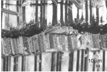
Observation of some sectioned specimens by an optical microscope showed matrix cracking, delamination and fibre fracture (two examples are reported in figure 4). The largest delamination was between the two external 0° plies on the back surface and the adjacent 90° plies; measurement of the diagonals of this delamination under the microscope confirmed the validity of the estimates made by visual inspection of the external surface of the specimen. Therefore a good approximation of the projected delaminated area was obtained as the area
Figure 4 – Sectioned laminates observed with an
optical microscope. a) Delamination between 90° and 45° layers (top right); delamination and matrix
cracking in the central group of plies with +/-45° fibre orientation. b) Delamination between two adjacent plies with the same fibre orientation (90°).
of a rhombus whose diagonals were measured visually in the principal directions of the lowermost ply. The following quantitative results refer to these estimates. In general, in the laminates which underwent higher energy events, delaminations in all interfaces between plies were observed. Internal alternated ±45° layers also showed extended delamination.
Figure 5 shows the energy absorbed by the specimens as a function of the energy imparted during impact or indentation. For impact tests, “total energy” means the kinetic energy of the impactor when contact initiated; in quasi-static indentation, “total energy” is the work done by the indentor during the loading phase of contact.
As figure 5a illustrates, the points relevant to different test conditions fall on different lines. The stiffer configurations absorbed a larger fraction of the total energy because they can store a lesser amount of elastic energy before damage initiation (see chapter 3, section 3.5). This explains why the energy absorption was larger in the smaller laminates, and also in the clamped specimens with respect to the supported ones. However, in each of the groups of
Figure 5 – Absorbed energy during impact or
indentation as a function of total energy. Filled symbols refer to impact tests, empty symbols refer to indentation tests. a) Overall diagram of the four test configurations. b) Clamped 200 mm specimens. c) Simply supported 200 mm specimens. d) Clamped 76 mm specimens. e)
coupons tested in the same configuration the energy absorption showed no appreciable difference between quasi-static and dynamic tests, as can be seen in figures 5b-e.
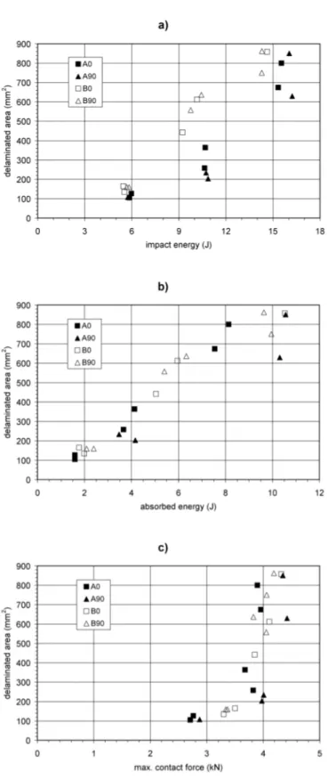
On the other hand, a small but evident difference between impact and indentation can be found if the delaminated area is plotted against the total energy (see figure 6) or the absorbed energy (see figure 7). In every configuration, the specimens subjected to quasi-static indentation underwent systematically larger delamination areas. In the case of 76 mm laminates with clamped boundary, the data obtained in impact and indentation seem to approach each other at the highest energy level. It should be noted, however, that in these cases the length of the major diagonal of the delaminated zone
reached approximately 75 mm after 10 ÷ 12 J events. Thus it is likely that at higher energies further propagation of delamination was prevented by the clamping rings.
Figure 6 – Delaminated area as a function of total
energy. Filled symbols refer to impact tests, empty symbols refer to indentation tests. a) Overall diagram
of the four test configurations. b) Clamped 200 mm specimens. c) Simply supported 200 mm specimens. d)
Clamped 76 mm specimens. e) Simply supported 76 mm specimens.
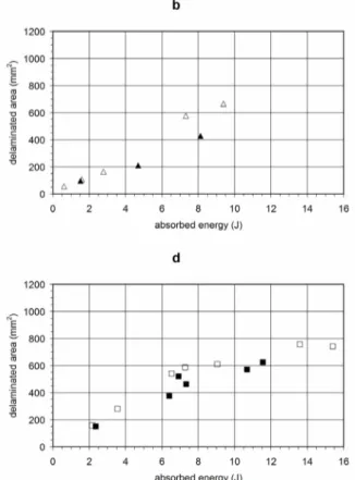
The diagram of delaminated area versus absorbed energy is of particular interest because for low velocity impacts a unique relationship can be found between these two quantities, regardless of the specimen diameter and boundary condition [6] (see chapter 3). Figure 7a confirms the
validity of this finding for the present impact tests, and indicates that a similar correlation holds for quasi-static indentation; however, in the latter case the delaminated area was greater in every test configuration (see figures 7b-e), or in other words a larger amount of energy was necessary in the dynamic tests to create the same damage area observed after the quasi-static ones.
Another difference was found regarding the maximum displacement of the impactor (or indentor), which turned out to be larger in the impact tests. Figure 8 presents plots of this quantity as a function of total energy. Again, the difference existed in all the test configurations considered, although is was clearly smaller in the 76 mm specimens (where it ranged from 0.3 to 0.5 mm) than in the 200
mm (where it was close to 1 mm).
Figure 7 – Delaminated area as a function of the energy
absorbed during impact or indentation. Filled symbols refer to impact tests, empty symbols refer to indentation tests. a) Overall diagram of the four test configurations. b) Clamped 200 mm specimens. c) Simply supported 200 mm specimens. d) Clamped 76 mm specimens. e)
Simply supported 76 mm specimens.
It is also interesting to examine the relationship between the delaminated area and the maximum contact force. Similarly to what happens with absorbed energy, in low velocity impact tests this relationship does not depend
on the specimen dimensions and boundary conditions [25] (see chapter 3). Figure 9 illustrates that this proved true also in the present research and, most importantly, no difference could be detected between impact and indentation.
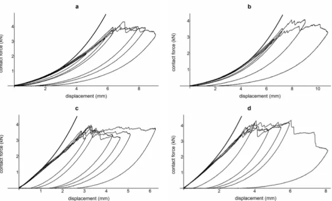
As in [25], the dependence of the delamination extent upon the maximum load showed a threshold behaviour, with very small damage areas for low force values and a rapid increase as soon as the load reaches a certain threshold, which for the present material can be located between 3.5 and 4.0 kN. The reason for this trend can be understood by considering the force-displacement diagrams obtained from the indentation tests (figure 10). As soon as the indentor displacement was large enough for the threshold load to be attained, the contact force could not increase any more, because further increase of the displacement led to a rapid propagation of the delamination. The
progression of damage was clearly signalled by significant noise during the tests, accompanied by the evident load drops visible in figure 10. The existence of another contact force threshold, probably smaller than 2 kN, can also be hypothesized based on the data reported in figure 9.
Figure 8 – Maximum displacement of the impactor or
indentor during impact or indentation, as a function of total energy. Filled symbols refer to impact tests, empty
symbols refer to indentation tests. a) Overall diagram of the four test configurations. b) Clamped 200 mm specimens. c) Simply supported 200 mm specimens. d)
Clamped 76 mm specimens. e) Simply supported 76 mm specimens.
This should be the limit load at which the first delamination (observed in all the specimens) was created, as stated also in [13, 25]. As long as the contact force was lower than 3.5 kN, the area of this initial delamination remained within 200 mm2, as can be seen in the diagram; beyond that load value, the delamination quickly began to propagate.
2.5. Results of the numerical analysis
2.5.1. Quasi-static indentation
When an immovable edge condition was imposed on the boundary of the clamped specimens, the results of numerical calculations, in terms of load-displacement curves, did not agree with the experimental observations, even for very low contact forces at which one can reasonably suppose that the material damage was absent or negligible. This error was attributed to the imperfect constraint
on the internal diameter of the clamping rings, where a small chamfer was machined in order to avoid crushing of the laminate due to the tightening load, as well as to facilitate handling of the
Figure 9 – Delaminated area as a function of maximum
contact force. Filled symbols refer to impact tests, empty symbols refer to indentation tests. a) Overall diagram of the four test configurations. b) Clamped 200
mm specimens. c) Simply supported 200 mm specimens. d) Clamped 76 mm specimens. e) Simply
rings. Of course such a constraint did not completely prevent the rotation of the specimen along its boundary.
Figure 10 – Contact force-displacement curves recorded during quasi-static indentation tests (thin lines) and
comparison with the numerically predicted behaviour for the loading phase (thick line). a) Clamped 200 mm specimens. b) Simply supported 200 mm specimens. c) Clamped 76 mm specimens. d) Simply supported 76
mm specimens.
To correctly reproduce the mechanical behaviour of the laminates, an elastic boundary condition was therefore applied to the rotation about the tangential direction along the circumference. The stiffness of this constraint was found by trial and error, comparing the numerical results to interpolations of the experimental load-displacement curves made according to the following formula [17]:
3 2 2⎤ ⎡ ⎤ ⎡ 3 2 3 1 ⎥⎥ ⎦ ⎢ ⎢ ⎣ ⎟ ⎠ ⎞ ⎜ ⎝ ⎛ − + ⎥ ⎥ ⎦ ⎢ ⎢ ⎣ ⎟ ⎠ ⎞ ⎜ ⎝ ⎛ − = k P w A k P w A P (2)
where the constants A1 and A2 were determined by least-square fitting, while the contact
stiffness k of expression (1) was assigned the value of 1.116 · 109 N/m3/2, as explained in section 2.3. w represents the overall displacement of the indentor, the quantity
(
is the indentation α as in (1), thus the difference)
2/3 / k P(
)
2/3 / k Pw− is the deflection of the laminated plate without including the local indentation. The formula (2) was chosen because it includes a linear flexural stiffness (A1) and a nonlinear membrane stiffness (A2), thus it can represent the
The interpolations of the experimental data were based on the load range between 0.2 and 0.5 kN; the points acquired at lower loads were excluded to discard possible errors in the force measurement, while at loads higher than 0.5 kN the results may have been influenced by material damage. The constraint stiffness per unit length was found to be 3.5 kNm/m for the 200 mm laminates and 2.0 kNm/m for the 76 mm laminates. With these values a very good agreement between experimental and numerical load-displacement curves was achieved until the material failed, as shown in figure 10.
Figure 11 – Tsai-Wu failure index calculated for the lowermost ply of laminates subjected to quasi-static
indentation with a numerically predicted contact force of 1 kN. a) Clamped 200 mm specimen. b) Simply supported 200 mm specimen. c) Clamped 76 mm specimen. d) Simply supported 76 mm specimen.
curves from the theoretical one was observed (see figure 10). This is most likely related to the first important material damage, probably the onset of the first delamination, deduced from the diagram in figure 9 as explained above.
However, the analysis of stresses in the laminates predicted the first failure at even smaller loads. The plots in figure 11 present the value of the failure index according to the Tsai-Wu criterion [26] calculated for the lowermost ply (opposite to the indented surface of the specimen), which was subjected to the highest stresses, and for a contact force of 1 kN. The index was larger than 1 (which in the present case corresponded to matrix failure in tension) in a wide region surrounding the indentation point. Therefore it can be concluded that the first damage, probably the initiation of the first back-face splitting of the laminate, did not produce any visible effect on the global mechanical behaviour of the specimens, as is pointed out also in [17]. It is possible that only the first delamination induced a stiffness loss large enough to become visible in the load-displacement curves.
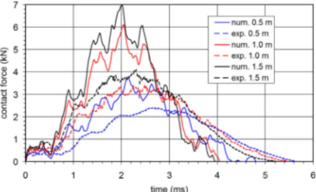
Figure 12 – Experimental (thin line) and numerical (thick line) contact force history for four representative
impact events (0.5 m drop height). a) Clamped 200 mm specimen. b) Simply supported 200 mm specimen. c) Clamped 76 mm specimen. d) Simply supported 76 mm specimen.
2.5.2. Low velocity impact
As for the quasi-static indentation experiments, an analogous comparison between numerical and experimental results can be carried out for the low velocity impact tests. Such a comparison is reported in figure 12, where the contact force is plotted as a function of time for one representative test of each configuration, and in figure 13, where three impact events at different
drop heights are collected. In the numerical model, an elastic constraint was applied to the boundary of the clamped plates, with the same stiffness already used for the quasi-static tests.
These diagrams show a reasonably good agreement at force levels within 1.0 ÷ 1.5 kN. Beyond this limit, which was difficult to evaluate exactly due to the oscillations, the numerical calculation generally overestimated the contact load, similarly to what happened in the analysis of the indentation tests. Again, the disagreement can be attributed to the progressive propagation of damage in the laminates. It can be noted from the curves in figure 13 that the difference between numerical and experimental results became larger and larger for increasing impact energy and consequent damage in the specimen.
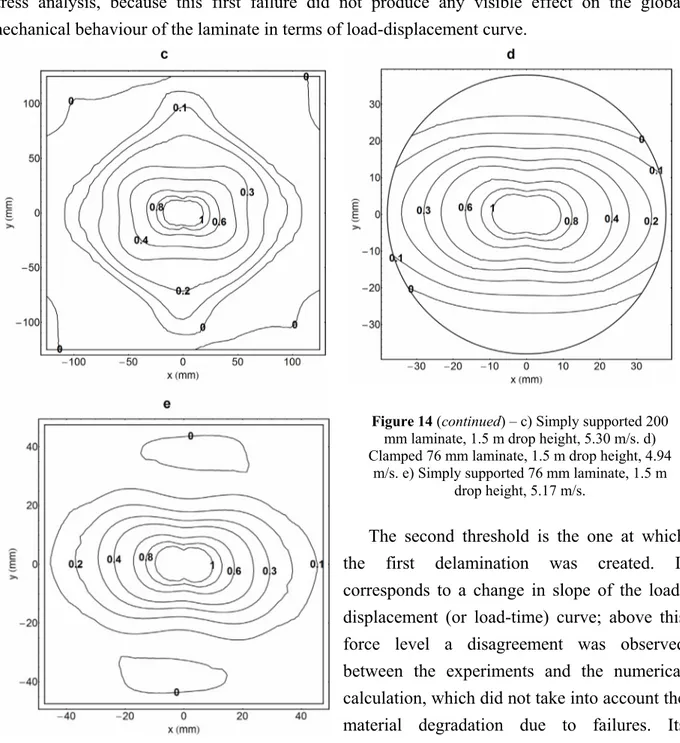
Figure 14 presents some representative plots of the Tsai-Wu failure index calculated for the lowermost ply, which was subjected to the highest stresses in every case. All the images refer to instants at which the contact force was exactly 1 kN, and can thus be directly compared to the pictures in figure 11. The difference between quasi-static and dynamic tests was found to be negligible, except for the case of the clamped 200 mm laminate of figures 14a-b. These two images refer to the same impact event whose contact force history is plotted in figure
13c, and represent the stress state in two distinct instants at the beginning of contact, at both of which the predicted load was equal to 1 kN. A slight difference can be seen between them and also with respect to figure 11a which refers to the same contact force applied quasi-statically. This can help in establishing to what extent the impact velocity can be considered low in the present test configuration, according to the second definition previously cited [7].
Figure 13 – Experimental (thin line) and numerical
(thick line) contact force history for three representative impact events with different drop heights on clamped 200 mm laminates. a) 0.5 m drop
height (impact velocity 3.10 m/s). b) 1.0 m drop height (impact velocity 4.34 m/s). c) 1.5 m drop
height (impact velocity 5.18 m/s).
That definition is based on the propagation of elastic waves from the impacted point towards the boundary. Thus the larger the in-plane dimensions of the specimen, the longer the time required for the waves to reach the boundary. As a consequence, contact duration remaining
equal, the response of the larger specimen will be more evidently affected by wave propagation. The greater amplitude of the secondary oscillations in the contact force history of the 200 mm with respect to the 76 mm specimens demonstrates this fact. For this reason it can be expected that the upper limit of the low impact velocity range will be smaller for the 200 mm specimens, and that the behaviour of the larger laminate impacted from the greatest drop height will be the most significantly influenced by wave propagation. This is confirmed by the stress plots in figure 14. The faint difference between the quasi-static state in figure 11a and the dynamic counterparts in figures 14a-b may indicate that for the 200 mm laminate of the present study an impact velocity of 5 m/s can actually be considered low, but is not far from the limit of the low range.
Figure 14 – Tsai-Wu failure index calculated for the lowermost ply of laminates subjected to low velocity
impact, at an instant at which the numerically predicted contact force was 1 kN. a) Clamped 200 mm laminate, 1.5 m drop height, 5.18 m/s, 340 μs after the beginning of contact. b) The same as in a), but 643 μs after the
beginning of contact.
2.6. Comparison between impact and indentation
As pointed out above, the test conditions considered in the present study met both the second definition of low velocity impact [7] and the first one [6], since the impact velocity was much lower than the typical threshold of 10 ÷ 20 m/s. Therefore it is meaningful to compare the experimental results obtained in impact with the ones of quasi-static indentation.
From the results of the experimental tests and of the numerical simulation, it was possible to deduce the existence of three contact force thresholds which played an important role in the progression of material damage.
The first one is the load at which the very first damage took place, probably in the form of a matrix fracture on the back face of the specimen under the impact or indentation point. The existence of this characteristic force level could be hypothesized only by means of the numerical
stress analysis, because this first failure did not produce any visible effect on the global mechanical behaviour of the laminate in terms of load-displacement curve.
Figure 14 (continued) – c) Simply supported 200
mm laminate, 1.5 m drop height, 5.30 m/s. d) Clamped 76 mm laminate, 1.5 m drop height, 4.94
m/s. e) Simply supported 76 mm laminate, 1.5 m drop height, 5.17 m/s.
The second threshold is the one at which the first delamination was created. It corresponds to a change in slope of the load-displacement (or load-time) curve; above this force level a disagreement was observed between the experiments and the numerical calculation, which did not take into account the material degradation due to failures. Its existence could also be inferred from the relationship between delaminated area and maximum contact force (figure 9): although a delamination was found after all the tests, it is obvious that if the imparted energy was small enough no delamination would be induced [13, 25].
The third characteristic force is the one beyond which the delamination area began to increase very rapidly, as shown in figure 9. It can be recognized only by analysing the experimental data, because the results obtained by the numerical model, which did not account for damage, were not reliable at this load level.
The present research demonstrates that, at least in the impact velocity and energy range considered, these contact force thresholds are equal for low velocity impact and quasi-static indentation, within the attainable experimental accuracy. This agrees with the conclusions of