The afocal telescope optical design and tolerance analysis for the ESA ARIEL
mission
Title
Da Deppo, Vania; Middleton, Kevin; FOCARDI, MAURO; MORGANTE,
GIANLUCA; Grella, Samuele; et al.
Authors
10.1117/12.2292299
DOI
http://hdl.handle.net/20.500.12386/26635
Handle
PROCEEDINGS OF SPIE
Series
10590
Number
SPIEDigitalLibrary.org/conference-proceedings-of-spie
The afocal telescope optical design
and tolerance analysis for the ESA
ARIEL mission
Vania Da Deppo, Kevin Middleton, Mauro Focardi,
Gianluca Morgante, Samuele Grella, et al.
The afocal telescope optical design and tolerance analysis for
the ESA ARIEL mission
Vania Da Deppo*
a,b, Kevin Middleton
c, Mauro Focardi
d, Gianluca Morgante
e, Samuele Grella
f,
Riccardo Claudi
b, Emanuele Pace
g, Iacopo Ficai Veltroni
f, Giuseppina Micela
ha
CNR-Istituto di Fotonica e Nanotecnologie, Padova, Via Trasea 7, 35131 Padova, Italy
bINAF-Osservatorio Astronomico di Padova, Vicolo dell’Osservatorio 5, 35122 Padova, Italy
c
RAL Space-STFC Rutherford Appleton Laboratory, Harwell Campus, Didcot OX11 0QX, UK
d
INAF-Osservatorio Astrofisico di Arcetri, Largo E. Fermi 5, 50125 Firenze, Italy
eINAF-IASF Bologna, Area della Ricerca, Via Piero Gobetti 101, 40129 Bologna, Italy
f
Leonardo S.p.A., Via delle Officine Galileo 1, 50013 Campi di Bisenzio (FI), Italy
gDip. di Fisica ed Astronomia-Università degli Studi di Firenze, Largo E. Fermi 2, 50125 Firenze,
Italy
h
INAF-Osservatorio Astronomico di Palermo, Piazza del Parlamento 1, 90134 Palermo, Italy
ABSTRACT
ARIEL (Atmospheric Remote-sensing Infrared Exoplanet Large-survey) is one of the three present candidates for the next ESA medium-class science mission (M4) to be launched in 2026. During its 3.5 years of scientific operations from L2 orbit, this mission will observe spectroscopically in the infrared (IR) a large population of known transiting planets in the neighbourhood of the Solar System. The aim is to enable a deep understanding of the physics and chemistry of these exoplanets.
ARIEL is based on a 1-m class telescope ahead of a suite of instruments: two spectrometer channels covering the band 1.95 to 7.80 µm and four photometric channels (two wide and two narrow band) in the range 0.5 to 1.9 µm.
The ARIEL optical design is conceived as a fore-module common afocal telescope that will feed the spectrometer and photometric channels. The telescope optical design is based on an eccentric pupil two-mirror classic Cassegrain configuration coupled to a tertiary paraboloidal mirror.
An all-aluminum structure has been considered for the telescope layout, and a detailed tolerance analysis has been conducted to assess the telescope feasibility. This analysis has been done including the different parts of the realization and life of the instrument, from integration on-ground to in-flight stability during the scientific acquisitions.
The primary mirror (M1) temperature will be monitored and finely tuned via an active thermal control system based on thermistors and heaters. The heaters will be switched on and off to maintain the M1 temperature within ±1K thanks to a proportional–integral–derivative (PID) controller.
Keywords: space instrumentation, telescope, optical design, tolerance analysis, exoplanetary science, thermal control.
1. INTRODUCTION
ARIEL is one of the M4 proposed missions in the framework of the ESA Cosmic Vision program [1]. The ARIEL mission will address the fundamental questions on what exoplanets are made of and how planetary systems form and evolve by investigating the atmospheres of many hundreds of diverse known exoplanets orbiting different types of nearby stars [2]. More than three thousand exoplanets have now been discovered and confirmed; Gaia [3], Kepler [4] and K2 [5], together with other current ground and space-based surveys, will continue to increase the known exoplanet list. However, at present, very little is known about the nature of these exoplanets.
*[email protected]; phone +39-049 9815639; fax +39-049 774627
International Optical Design Conference 2017, edited by Peter P. Clark, Julius A. Muschaweck, Richard N. Pfisterer, John R. Rogers, Proc. of SPIE-OSA Vol. 10590, 105901P · © 2017 SPIE
During its 3.5-year scientific mission lifetime in L2 orbit, the ARIEL mission aims to measure the atmospheric composition and structure of a large and well-defined selected sample of exoplanets (∼1000). It will use transit spectroscopy in the 1.25-7.80 μm spectral range and multiple narrow-band photometry in the optical.
For its ambitious scientific program, ARIEL is designed as a dedicated survey mission for transit and eclipse spectroscopy. Whereby the signals from the star and planet are differentiated using knowledge of the planetary ephemerides, transit, eclipse and phase-curve spectroscopy methods allow to measure atmospheric signals from the planet at levels of 10-100 part per million (ppm) relative to the star and, given the bright nature of the targets, also allow more sophisticated techniques, such as eclipse mapping, to give a deeper insight into the nature of the atmosphere [6].
Transit spectroscopy means that no angular resolution is required and detailed performance studies, carried out by the ARIEL Consortium, show that a telescope collecting area of 0.64 m2 is sufficient to achieve the necessary observations
on all the ARIEL targets within the mission lifetime [7].
ARIEL will host a telescope unit feeding a collimated beam into two separate modules. The first is a combined Fine Guidance System(FGS)/VIS-Photometer/NIR-Spectrometer that contains three photometric channels in the wavelength range between 0.50 μm and 1.2 μm to monitor the photometric stability of the target stars. Two of these channels will also be used as a prime/redundant system for providing guidance and closed-loop control to the high stability pointing Attitude and Orbit Control System (AOCS) of the spacecraft (S/C). Integrated in this same module is a further low-resolution (R=~10) NIR spectrometer channel in the 1.2–1.95 μm waveband. This first combined module is often simply referred to as the FGS. The second module, acting as the main instrument, is the ARIEL IR Spectrometer (AIRS), providing variable resolving power in the range 30–180 for a waveband between 1.95 μm and 7.80 μm.
The ARIEL S/C is composed of a cold Payload Module (PLM), containing the telescope and the instruments with their thermo-mechanical hardware, and a warm Service Module (SVM) that includes all the mission supporting systems together with the PLM and cryogenic control units [8]. The PLM will interface to the SVM via a set of thermally isolating support struts, or bipods, and will be radiatively shielded from the SVM and the solar input loads by a set of 3 V-Grooves (VGs). The payload is passively cooled to ~50 K. The AIRS detectors are the only items that require active cooling to <42 K via an active Ne-based JT cooler.
ARIEL will be highly complementary to other international facilities (such as TESS [9], to be launched in 2018) and will benefit from other ESA exoplanet missions such as CHEOPS [10] and PLATO [11], which will help to provide an optimized target list prior to launch.
2. TELESCOPE OPTICAL CONFIGURATION
2.1 ARIEL mission and science requirements
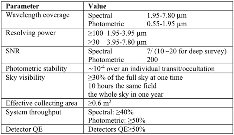
The key science performance parameters that will drive the specification of the ARIEL mission have been identified by the Science Study Team (SST) [12].
Table 1. ARIEL main science and mission requirements.
Parameter Value
Wavelength coverage Spectral 1.95-7.80 μm Photometric 0.55-1.95 µm Resolving power ≥100 1.95-3.95 μm
≥30 3.95-7.80 μm
SNR Spectral 7/ (10∼20 for deep survey) Photometric 200
Photometric stability ∼10-4 over an individual transit/occultation
Sky visibility ≥30% of the full sky at one time 10 hours the same field the whole sky in one year Effective collecting area ≥0.6 m2
System throughput Spectral: ≥40% Photometric: ≥50% Detector QE Detectors QE≥50%
These requirements have been derived starting from the science objective, and they include: the wavelength coverage, spectral resolving power, signal-to-noise ratio and noise requirements, photometric stability, sky visibility/source accessibility, temporal resolution, limiting targets, calibration, zodiacal light and background. Starting from the science requirements, the SST has then derived the mission requirements [13]. In Table 1 the most important science and mission requirements for the spectral and photometric observations are reported.
2.2 Telescope design requirements
The telescope has been designed in order to provide the optical requirements reported in Table 2, which have been derived from the mission requirements. The requirement on the collecting area of at least 0.6 m2 implies an entrance pupil of the
order of 1 m in diameter. The collecting area is related with the minimum intensity (magnitude) of the observable targets. Table 2. Summary of the telescope optical requirements.
Parameter Value
Collecting area >0.6 m2
FoV 30" with diffraction limited performance
41" with optical quality TBD allowing FGS centroiding 50" unvignetted
WFE Diffraction limited @ 3 μm Wavelength range 0.55–8 μm
Throughput Minimum >0.78 Average >0.82 Output beam dimension 20 mm x 13.3 mm
The design performance is driven by the requirement that the final as-built quality of the telescope system has to be diffraction limited at 3 µm over a FoV of 30", i.e. equivalent to an RMS wavefront error (WFE) of 220 nm.
To guarantee the required throughput without increasing the size of the primary mirror, that is the entrance pupil of the telescope, the optical design has to be unobscured. The unobstructed solution also assures the energy in the PSF is primarily contained inside the first Airy disk and not spread towards the secondary rings.
The wavelength coverage and the global FoV of the telescope are determined by the requirements on the instruments following the telescope, i.e. the FGS and the AIRS [14].
2.3 Telescope design characteristics
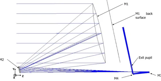
The baseline telescope design is an afocal unobscured eccentric pupil Cassegrain telescope (M1 and M2) with a recollimating off-axis parabolic tertiary mirror (M3). All the mirrors share the same optical axis. An M4 plane mirror redirects the exiting beam parallel to the back of M1 where the Optical Bench (OB) is located and the FGS and AIRS will be mounted (see Figure 1).
The telescope is accommodated horizontally with its optical axis (Z) along the S/C X axis [15][16]. The centre of the FoV of the telescope is inclined of 0.1° in the YZ plane with respect to the optical axis of the telescope defined by the mirrors common optical axis.
The system aperture stop/entrance aperture is located at the M1 surface. The M1 aperture is an ellipse with major/minor axes dimensions of 1100 mm x 730 mm. The complete characteristics of the optical design are summarized in Table 3a, while in Table 3b the telescope mirror parameters (radius of curvature, conic constant, off-axis, etc.) are described. M2 will be equipped, as baseline, with a refocusing and tip/tilt mechanism. There will be also an eccentric baffle around M1, internal vanes between M1 and M2, M2 and M3, field and Lyot stops to control and limit both the out-of-field and in-field scattered straylight. To check the calibration of the spectrometer module in-flight, an IR calibration source is foreseen.
M2 M1 back surface M4 Exit pupil M3
Figure 1. Scale drawing of the telescope – view in Y-Z plane.
Table 3. (a) Summary of the telescope optical design characteristics. (b) Mirrors parameters description.
(a) (b) Optical element M1 M2 M3 R (mm) -2319.5 -239.0 -491.5 k -1 -1.4 -1 Off-axis (mm) (y direction) 500 50 20 Clear Aperture Radius (mm) Elliptical, 550 (x) by 365 (y) Elliptical, 56 (x) by 40 (y) Elliptical, 15 (x) by 11 (y)
Type Concave mirror Convex mirror Concave mirror
2.4 Telescope optical performance
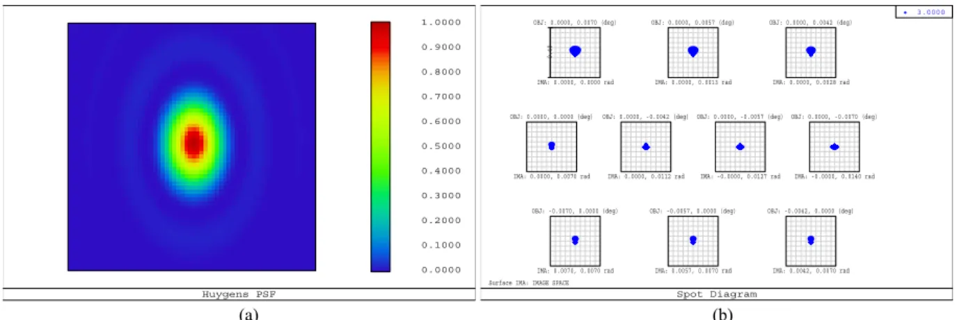
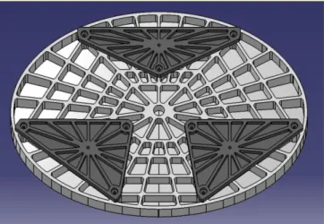
The raytracing analysis and design optimization have been done by means of the raytracing software Zemax®. Since the telescope is afocal, to assess the quality of the telescope and determine the optical performance, the spot diagrams can be given using an ideal focusing paraxial lens with a defined focal length, or using the afocal image space option appropriate for systems with collimated output. Note that the spot diagrams obtained with this second method have their size expressed in milliradians.
The nominal diffraction PSF at 3 µm wavelength has an Airy radius respectively of 0.2 mrad and 0.29 mrad in the X and Y directions. A picture of the expected theoretical PSF is depicted in Figure 2a; in Figure 2b for comparison the spot diagrams all over the 50" unobstructed telescope FoV are drawn and compared with a box of 0.4 mrad size, so to show that telescope design is diffraction limited at the 3 µm primary wavelength.
The telescope RMS WFE is always less than 26 nm over the 30" nominal telescope FoV (see Figure 3); this value is well below the telescope diffraction limit at 3 µm, i.e. 220 nm.
Parameter Values
Optical concept Afocal design. Eccentric pupil Cassegrain telescope plus
off-axis paraboloidal mirror and folding. Focal length 14.17 m FoV centre 0.1° - Off-axis YZ plane Pupil size Ellipse with major axis
1.1 m x 0.73 m Focal ratio @
intermediate
telescope focus 13 (x)/19.4 (y) Angular
(a) (b)
Figure 2. In (a) PSF calculated at the telescope FoV centre for a wavelength of 3 µm depicted over a 1 mrad square box. In (b) Spot Diagrams in the afocal space; the scale (box) is 0.4 mrad.
-30 -20 -10 0 10 20 30 20 25 30 35 R M S_w a ve fr o nt_ er ( nm ) FoV(") (a) (b)
Figure 3. In (a) RMS WFE field map calculated for the 3 µm wavelength over the 30" nominal telescope FoV. Units are λ. In (b) cross section along the Y direction of the RMS WFE expressed in nm; in the X direction the WFE is constant.
3. TOLERANCE ANALYSIS
A detailed trade-off for the material to be used for the telescope mirrors, specifically for M1, and telescope structure has been carried out during the ARIEL assessment phase. The conclusion is that for the consortium provision of the telescope the optimum solution is a telescope with mirrors and structure made from aluminum 6061 T651 alloy [17]. The viability of using aluminum as the baseline material for the telescope mirrors has been assessed during the phase A by producing a pathfinder M1 mirror [14].
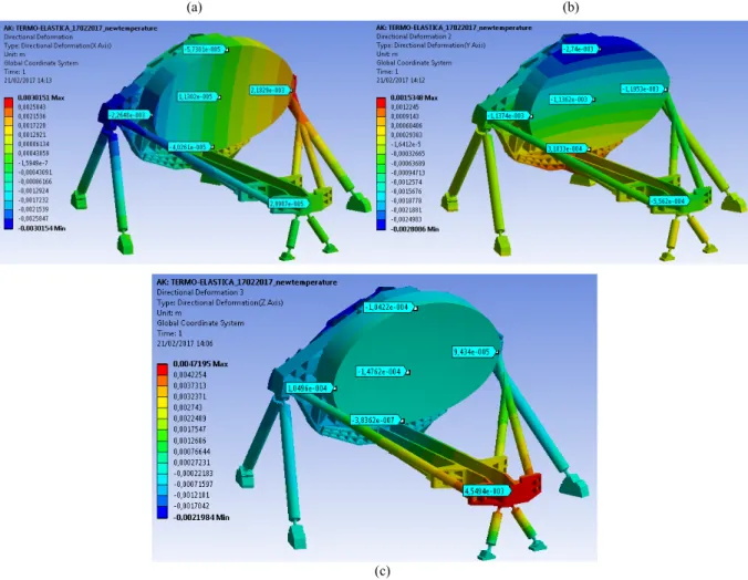
The primary mirror will be lightened and its mechanical shape is studied in order to give high bending stiffness both during manufacturing and in operating condition. The selected mounting system ensures isostatic thermal fixation of the primary mirror. M1 is supported directly by the OB via a 9-point whiffletree structure, which is connected to the OB via three triangular mountings. The M1 mechanical configuration is shown in Figure 4.
A static analysis has been done to assess the deformation of the M1 surface due to gravity. Different mounting plate materials have been considered. With an Al 6061 mounting plate, the expected surface distortion PTV is of the order of 100 nm, which corresponds to approximately 40 nm RMS.
To assess the final performance of the as-built telescope and its variation during the operation in flight, a tolerance analysis has been done [18] [19]. The telescope has been considered to be designed, realized and integrated at room temperature in 1g environment according to the raytraced theoretical layout. Being an all-aluminum instrument, it is expected to scale
0.0000 0.1000 0.2000 0.3000 0.4000 0.5000 0.6000 0.7000 0.8000 0.9000 1.0000 Huygens PSF
Surface IMA: IMAGE SPACE
0. 40 OBJ: 0.0000, 0.0070 (deg) IMA: 0.0000, 0.0000 rad OBJ: 0.0000, 0.0057 (deg) IMA: 0.0000, 0.0013 rad OBJ: 0.0000, 0.0042 (deg) IMA: 0.0000, 0.0028 rad OBJ: 0.0000, 0.0000 (deg) IMA: 0.0000, 0.0070 rad OBJ: 0.0000, -0.0042 (deg) IMA: 0.0000, 0.0112 rad OBJ: 0.0000, -0.0057 (deg) IMA: -0.0000, 0.0127 rad OBJ: 0.0000, -0.0070 (deg) IMA: -0.0000, 0.0140 rad OBJ: -0.0070, 0.0000 (deg) IMA: 0.0070, 0.0070 rad OBJ: -0.0057, 0.0000 (deg) IMA: 0.0057, 0.0070 rad OBJ: -0.0042, 0.0000 (deg) IMA: 0.0042, 0.0070 rad 3.0000 Spot Diagram 6.51E-003 6.70E-003 6.89E-003 7.09E-003 7.28E-003 7.47E-003 7.66E-003 7.85E-003 8.04E-003 8.24E-003 8.43E-003
down when cooling down at the nominal operating temperature. To compensate for residual mechanical deformations of the telescope due to the cooling process, the secondary M2 refocusing mechanism can be used.
Figure 4. Primary mirror rear side with the foreseen mounting scheme.
The tolerance analysis has taken into account the different parts of the realization and life of the instrument: 1. manufacturing, integration and alignment;
2. launch loads and change from 1 g to 0 g;
3. cooldown in orbit from ambient temperature to the nominal (about 50 K) operating temperature;
4. stability in flight: short term (over 1 single exposure of about 10 hours) and long term (over the whole mission operative lifetime).
For the manufacturing, integration and alignment phase optical element standard manufacturing and mounting tolerances have been taken into account. The considered manufacturing tolerances are shown in Table 4. For the mounting of each optical element, errors of about 0.1 mm in position and 20÷30" in orientation have been assumed.
Table 4. Telescope optical element manufacturing tolerances.
Mirror ΔR (mm) Ab. (sph/coma/ast) Dec X&Y (mm) Rot X&Y (")
M1 0.2 λ/3 PTV each ±0.1 25
M2 0.02 λ/10 PTV each ±0.1 25
M3 0.5 λ/10 PTV each ±0.1 25
M4 (Δ 1/R) 2 10-6 λ/12 PTV sph - -
The mirrors are foreseen to be equipped with a reference cube, or reference surfaces, and, with respect to these references, the mirror local axis will be measured with high precision (∼10/20 microns in position and 2/4" in rotation). If after manufacturing, M1 will be measured and found to be out of the specifications, to avoid the time consuming process of re-working a 1 meter diameter mirror, the possibility of re-optimizing M2 will be considered.
Table 5. Telescope manufacturing and alignment optical tolerances (a) and compensators (b).
(a) (b) Parameter M1 M2 M3 M4 ΔR (µm) 240 24 450 Δ 1/R (mm-1) 5 10-7 Surf_Irr_PTV (λ) 1 1/3 1/3 1/12 Dec X&Y (µm) 150 150 150 - Rot (") 30 30 30 30 Dec Z (µm) 150 150 200 150 Compensator Value Dec_M2 (µm) 200 Rot_M2 (") 60 Dist_M1_M2 (µm) 200 Rot_M4 (") 60 (TBD)
AK: TERMO- ELASTICA 17022017 newtemperature
Directional Deformation 3 Type: Directional Deformation(ZQXis) Unit: m
Global Coordinate System Time: 1 21/02/201.7 1.4:06
i
0,0047195 Max 0,0042254 0,0037313 0,0032371 0,002743 0,0022489 0,0017547 0,0012606 0,00076644 0,00027231 -0,00022183 nn0071597 -4,0012101 -0,0017042 -0,0021984 MinAN: iFRMOfLPSILCF 1]02101] newtempeaature
Deecnonel Delmma0on
ypeDne uonaiDelonnation(XAtis)
Unit 333
4iobaiCao:tl mete iyvtem
ene:l 11/01/101714 13 40030151 Mae 0,0015043 0,0031536 0,0017330 0,0013931 0,00006134 000043059 000043091 00006166 00011914 00011111 00011519 00015047 40030154 Min
AIl:TERMO- ELISEG'L17022017-newtemperature Oirecional Reformation z
Type: Girecionei Geformotnn(VMe)
worm
Global CooniMate System
lime: 1 31/03/2017 74 :7E 0,001' Max 0,0013345 0,0009143 0,00060406 0,00039303 -1,6412e -5 -0,00033665 000063669 000094713 00011511 00015616 00018)18 00011881 00018981 -0,0038086 Min
The adopted alignment philosophy is to mount M1 and then, with the help of the reference surfaces, measure its positon and orientation and use M2 as compensator to recover the optical quality. In Table 5 the derived telescope manufacturing and alignment tolerances are shown. They include the tolerance on the curvature radius, surface irregularity, decenter and tilt of the mirrors as well as the values of the possible compensators.
The total impact of the manufacturing, integration and alignment process on the RMS WFE is expected to be of the order of 40 nm.
To reduce the deformation effects induced by gravity during the alignment and tests on-ground, a slightly inclined position of the telescope, with the gravity acting parallel to the optical bench, is suggested to be adopted. The whole telescope structure should be rotated about 12° with respect to the telescope interface to SVM [14].
A preliminary thermoelastic analysis has been performed to verify the deformation of the primary mirror and the telescope structure during the cooling phase from ambient 293 K to the operating temperature. The considered operating temperature map is the one calculated using the thermal model for the reference worst case condition (“Cold Case”, see the following section). The obtained resulting deformations are reported in Figure 5. The variation of the distance between the centres of primary and secondary mirrors is of about 20 µm along the X direction, about 600 µm and 4.7 mm respectively in the Y and Z ones. These numbers are in line with the expected displacements, in fact the mean Al6061 coefficient of thermal expansion (CTE) in the considered temperature range is about 17 μm per meter per degree.
(a) (b)
(c)
Figure 5. In (a) (b) (c) telescope directional deformations respectively along the X, Y and Z axes resulting from the thermoelastic analysis. Units are meters.
Choosing some reference points (nodes) on the primary and secondary mirrors and comparing the node expected positions, calculated with the simple scaling of the design, with the ones derived by the thermoelastic analysis, the residual deformations of the telescope have been derived. The telescope results to be rotated approximately 4' around the X axis, the distance between M1 and M2 is about 200 µm more than expected and the estimated variation for the shape of the primary mirror is about 20 µm PTV. The first effect can be recovered re-orienting the whole S/C, the second, and partly the third, by moving M2 via the refocusing mechanism. The residual WFE after refocusing is expected to be of the order of 200 nm.
For the stability in-flight, at present, the foreseen seasonal changes are estimated to be less than 1 K corresponding to an expected RMS WFE of about 130 nm. The related movements and deformations for the optical element are reported in Table 6. If considered necessary, the M2 refocusing mechanism can be used from time to time to recover the WFE changes. During one single exposure, i.e. up to 10 hours, the temperature variation is negligible, of the order of a few mK, and the induced boresight errors will be recovered by using the FGS.
Table 6. Telescope long term stability tolerance.
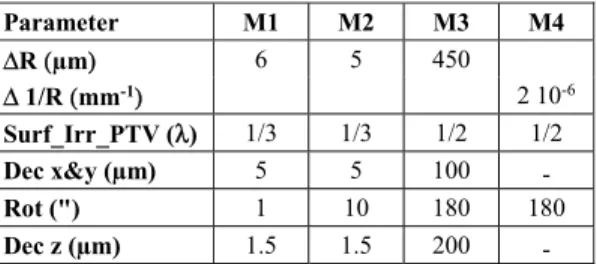
Parameter M1 M2 M3 M4 ΔR (µm) 6 5 450 Δ 1/R (mm-1) 2 10-6 Surf_Irr_PTV (λ) 1/3 1/3 1/2 1/2 Dec x&y (µm) 5 5 100 - Rot (") 1 10 180 180 Dec z (µm) 1.5 1.5 200 -
The results of the whole tolerance analysis have been summarized in Table 7. The telescope, thermally stable after cooldown and refocused via the M2 mechanism, will have a WFE of the order of 220 nm RMS and the total RMS WFE error in flight, including the stability, will be within 250 nm.
Comparing these results and the WFE budget, detailed in [14], it can be demonstrated that the telescope assembly will deliver the required optical quality suitable to achieve the scientific purpose of the instrument.
Table 7. Tolerance summary results.
Mission phase RMS_Wv_Err (nm)
Man&Align 40 Launch+1g->0g 50 Cool down 210 TOT. ‘as-built’ 220 In-flight stability 130 TOT. + stability 250
4. TELESCOPE THERMAL ANALYSIS AND CONTROL
The telescope is passively cooled to ≤70 K and its thermal control is based on a passive/active approach. A high efficiency thermal shielding system (see Figure 6) based on a multiple radiators configuration can provide stable temperature stages down to 50-60 K in the L2 orbit environment.
Temperature control of the mirrors is achieved by partial thermal decoupling from PLM units: each mirror is mounted on its supporting structure by insulating struts with a total conductance of less than 0.1 W/K. This configuration will help in filtering out all potential instabilities with periods of the order of 10–100 s originated in the payload module and longer than the expected single exposure times.
For the primary mirror, the high thermal capacitance, due to its mass, will allow a higher level of passive filtering, damping instabilities at lower frequencies, i.e. with periods of the order of few hours. The slower fluctuations, with periods of the
COLD
M2
t
toSpace
Telescope Baffle Instrument
Box -
q to
IRpBox Space
F =
tzli TG9 Ñ 1/CS v6510011406 Ó EaSIlGEE
.4 M1 ñ J,. ú M_¡I
AIRS Box op ot ó TIF6'
OB Beam q TIF3 to VGroove3 t HK'-r n_ L
TIF2to VGroove2&
TIFI to VGroove1
Harness .
.IIn!¡
®
TIFO to SVM. - Top SVM MLI
WARM
SVM
Warm Electronics Cooler - Compressor ó.^
Insulating Strut Conductive Strut Thermal Strap - Harness <_ 55K 100K11
-
T Stages to Spaceorder of several hours or longer, that could be transmitted to the optics will be smoothed by the active control system based on a PID type feed-back loop.
Figure 6. PLM thermal architecture scheme [15].
The telescope will also incorporate contamination control heaters on the M1 and M2 mirrors and on the OB. These heaters will be active during the early orbit operations to ensure that the sensitive optical surfaces remain warmer than the support structure through the critical parts of cooldown. A temperature delta of ~40 K will be maintained between the baffle, which will act as a contamination getter for water and other contaminants being off-gassed by the PLM, and the optical surfaces.
A thermal analysis has been performed at PLM level. Both steady state and transient studies have been carried out for different boundary conditions on the SVM top plate and SVM radiative shield. The expected steady-state temperatures in the nominal operating conditions, corresponding to the S/C orbiting around the Sun-Earth L2 point, have been calculated as well as transients induced by an abrupt change of the boundary conditions. Also the cooldown from ambient temperature to the operative condition in orbit, calculated over a 30 days period, has been simulated [20].
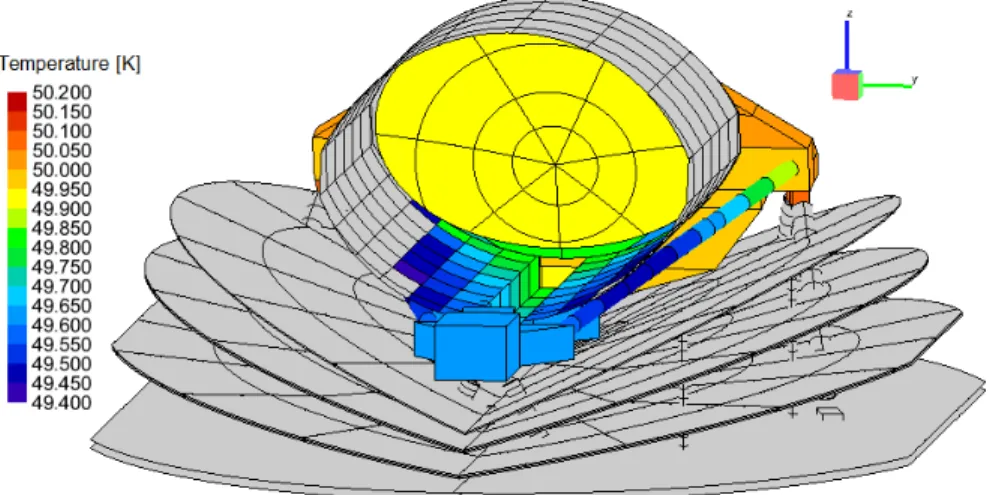
The steady-state results obtained for the cold PLM in the coldest operative case (‘Cold Case’) has been taken as a reference. In fact, the ‘Cold Case’ corresponds to the situation in which the payload reaches the lowest temperature thus resulting in the worst condition for what concerns the thermoelastic deformation effects on the payload. The temperatures reached by all passively and actively cooled units are fully compliant with the requirements including margins. Figure 7 reports a detailed view of the telescope assembly temperatures.
Thermal stability is one of the key issues of the ARIEL PLM thermal design. For this reason, an analysis case has been computed to check the impact on the PLM of a temperature variation of 10 K of the SVM platform conductive interface during a nominal observation run of 10 hours. The corresponding total change (over the 10-hour period) of the M1 node temperatures is less than 0.5 mK, even in the case of a sudden change (step function) or of a linear variation imposed at
Temperature [K] 50.200 50.150 50.100 50.050 50.000 49.950 49.900 49.850 49.800 49.750 49.700 49.650 49.600 49.550 49.500 49.450 49.400
the SVM interface. The preliminary results of the analysis on the cooldown show that after 30 days the passive cooldown is concluded and the system can be considered in a steady-state thermal condition.
Summarizing the results of the thermal analysis, in routine science operation M1 operates at a temperature around 50 K with a very high level of thermal uniformity, better than 10 mK (see Figure 7), achieved by passive cooling. Even for the whole Telescope Assembly the total gradient between the mirrors and the structures results limited, of the order of 2 K. Moreover, transient simulations show that the telescope design, with the expected levels of temperature fluctuations on the SVM interface and on the OB, is already capable of filtering out most of the thermal instabilities down to oscillations of the M1 of the order of one mK or less.
Figure 7. Telescope assembly node temperatures in the ‘cold case’.
Anyway, the implementation on M1 of a fully redundant thermal control system (electrical resistances plus thermistors), fed by a PID type loop control logic driven by the Telescope Control Unit (TCU), is at present expected to ensure thermal stability even in the presence of oscillations with a wider frequency spectrum [14].
5. TELESCOPE CONTROL UNIT
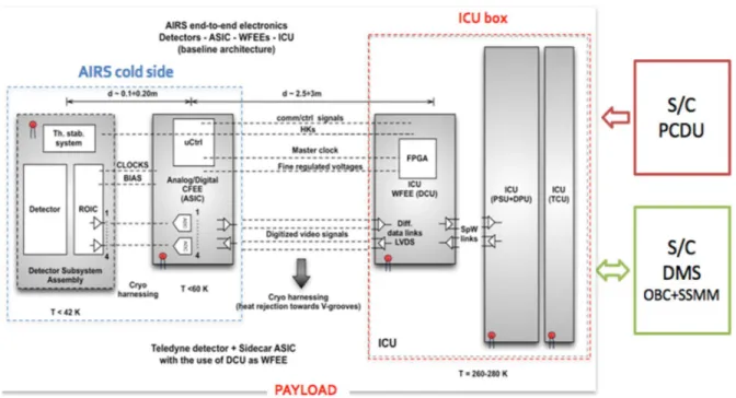
The ARIEL Instrument Control Unit (ICU) is the main electronic subsystem designed for scientific data pre-processing and to implement the commanding and control of the AIRS Spectrometer. The ICU is interfaced on one side with the instrument and on the other side, i.e. S/C side, with the Data Management System (DMS) and the Power Conditioning and Distribution Unit (PCDU), both belonging to the hosting platform [21] [22].
The DMS is composed of the On-Board Computer (OBC) and the Solid State Mass Memory (SSMM) operating as the main buffering memory for scientific data and HK telemetries before sending them to ground. For this reason, the ICU internal memories are basically conceived and designed for temporary local buffering and to support a reduced data handling as the AIRS scientific data, once properly pre-processed, are delivered to the SSMM.
This characteristic is exploited to simplify the unit electrical architecture (saving mass and power), designed at this stage of the project to be interfaced respectively to US detectors or EU detectors by means of their customized Cold Front-End Electronics (CFEE), operating at cryogenic temperatures.
As the ICU is hosted by a warm electronic box, it will be located inside the S/C SVM and connected to the AIRS CFEE by means of cryogenic harness. The ICU subsystem acting as interface to the cryogenic harness is a warm FEE (WFEE), called Detector Control Unit (DCU), as shown in Figure 8 and already developed for the Euclid/NISP instrument. The TCU, in charge of M2 mechanism and thermal control, is indeed considered an ICU slave subsystem and for its complexity and required volume is located in an independent box, with stacked drawers to the unit main box. The TCU will host the main logic board called Thermal Stabilizer (for the primary mirror Thermal Control System) & IR Calibrator (TSIRC), the M2 mirror mechanism (M2M) drivers and the needed power section to properly feed its subsystems.
-tz
-a
AIRS end -to -end electronics
Detectors - ASIC WFEEs ICU
(baseline architecture)
AIRS cold side
I
d 0.7e020m d-2.S«3m r ICU box Th stab. system Detector ROTC Detector Subsystem Assembly Cryo harnessing a CLOCKS BIAS uCtrl Analog,'Digdal CFEE (ASIC) T<aIK T <60 K comMCtrl signals HKs Mastar clock Fine reyulatsd voltagesDigitized videosignals
Cryo harnessing (heat rejection towards V.groovos)
Teledyne detector « Sidecar ASIC with the use of DCU as WFEE
PAYLOAD FPGA ICU WFEE (DCU) data links LVDS A 'Cu SpW lnks ICU ICU IPSUDPU) (TCU) T = 260.700 K
S/C
PCDUS/C
DMS OBC +SSMMFigure 8. On-board electronics architecture. 6. CONCLUSIONS
After a brief introduction on the ARIEL mission goals, the fundamental element of the payload, i.e. the front collecting telescope, has been presented. Its afocal layout solution has been described together with the different requirements and characteristics.
The chosen configuration is an un-obscured eccentric pupil Cassegrain plus a collimating off-axis paraboloidal mirror followed by a plane folding mirror. Its theoretical performance, i.e. spot diagrams, PSF and wavefront error, has been described.
Since an all-aluminum design solution has been considered as baseline, the results of a preliminary tolerance analysis have been shown to demonstrate that this choice is viable. The manufacturing, alignment and integration tolerance, the effects of the gravity and the cooling down in orbit have been considered together with the stability tolerance for the telescope when operating in-flight throughout all the mission lifetime.
The telescope is passively cooled at an operating temperature of about 50 K. A study of the passive/active thermal control of the instrument has been given. Finally, the end-to-end detection and data processing system, up to the Instrument Control Unit (ICU) and S/C main electrical subsystems, have been described.
ACKNOWLEDGMENTS
This activity has been realized under the Agenzia Spaziale Italiana (ASI) contract to the Istituto Nazionale di Astrofisica (INAF) (ARIEL 2015-038-R.0) and with the support of Leonardo S.p.A. (Campi di Bisenzio (FI) – Italy).
The authors gratefully acknowledge the support provided by the ESA ARIEL Study Team, the University College of London (UCL), leading the project, and the Rutherford Appleton Laboratory (RAL Space) managers and engineers. Thanks are also due to Fabio Zocchi and Marco Terraneo of Media Lario S.r.l. (Bosisio Parini (LC) –Italy) for the fruitful discussions on the manufacturing, alignment and integration tolerances.
REFERENCES
[1] Puig, L., Pilbratt, G. L., Heske, A., Escudero Sanz, I., and Crouze, P.-E., "ESA M4 mission candidate ARIEL", Proc. SPIE 9904, 99041W (2016).
[2] Tinetti, G., et al., "The science of ARIEL (Atmospheric Remote-sensing Infrared Exoplanet Large-survey)", Proc. SPIE 9904, 99041X (2016).
[3] Perryman, M. et al., "Astrometric exoplanet detection with Gaia", ApJ 797(14), (2014).
[4] Borucki, W. J. et al., "Kepler Planet-Detection Mission: Introduction and First Results", Science 327(5968), 977-980 (2010).
[5] Howell, S. B. et al., "The K2 Mission: Characterization and Early Results", PASP 126, 398-408 (2014). [6] ARIEL Science Study Team, "ARIEL Atmospheric Remote-sensing Infrared Exoplanet Large-survey – Enabling
Planetary Science across Light-years", Assessment Study Report (Yellow Book), ESA/SCI(2017)2, (2017). [7] Sarkar, S. et al., "ARIEL Performance Analysis Report", ARIEL-CRDF-PL-AN-001_2.2, (2017).
[8] Da Deppo, V., et al., "Design of an afocal telescope for the ARIEL mission", Proc. SPIE 9904, 990434 (2016). [9] Ricker, G. R., et al., "The Transiting Exoplanet Survey Satellite (TESS): discovering exoplanets in the solar
neighborhood", to be published in Proc. SPIE 9904, 9904-2B (2016).
[10] Fortier, A., et al., "CHEOPS: a space telescope for ultra-high precision photometry of exoplanet transits", Proc. SPIE 9143, 91432J (2014).
[11] Ragazzoni, R., et al., "PLATO: a multiple telescope spacecraft for exo-planets hunting", Proc. SPIE 9904, 990428 (2016).
[12] ARIEL SST, "ARIEL Science Requirements Document", ESA-ARIEL-EST-SCI-RS-001, (2015).
[13] ARIEL Science Study Team: ARIEL Mission Requirements Document, ESA-ARIEL-EST-MIS-RS-001, (2016). [14] Eccleston P. et al., "ARIEL Payload Design Description", ARIEL-RAL-PL-DD-001_2.0 (2017).
[15] Eccleston, P., et al., "An integrated payload design for the Atmospheric Remote-sensing Infrared Exoplanet Large-survey (ARIEL)", Proc. SPIE 9904, 990433 (2016).
[16] Da Deppo V. et al, "The afocal telescope of the ESA ARIEL mission: analysis of the layout”, Proc. SPIE 10398, 1039812 (2017).
[17] Da Deppo, V. et al., "ARIEL telescope material Trade-off", ARIEL-INAF-PL-TN-004_2.0 (2017).
[18] Da Deppo, V., et al., "The afocal telescope optical design and tolerance analysis for the ESA ARIEL Mission", OSA’s Optical Design and Fabrication Congress, Denver (USA), 9-13 July 2017 (2017).
[19] Sierra Roig, C., et al., "The ARIEL ESA mission on-board metrology", IEEE Workshop on Aerospace Metrology, Padova (Italy), 21-23 June 2017 (2017).
[20] D’Ascanio, D. et al., "PLM Thermal Analysis Report TMM/GMM Description and Results", ARIEL-INAF-TN-0003_2.0, (2017).
[21] Focardi, M., et al., "The ARIEL Instrument Control Unit design for the M4 Mission Selection Review of the ESA’s Cosmic Vision Program", to be published in Special Issue on ARIEL, Exp. Astron. (2017).
[22] Focardi, M., et al., "The Atmospheric Remote-sensing Infrared Exoplanets Large-survey (ARIEL) payload electronic subsystems", Proc. SPIE 9904, 990436 (2016).
![Figure 6. PLM thermal architecture scheme [15].](https://thumb-eu.123doks.com/thumbv2/123dokorg/8096024.124774/11.918.169.764.153.591/figure-plm-thermal-architecture-scheme.webp)