UNIVERSIT`
A DI PISA
Laurea Magistrale in Ingegneria
Robotica e dell’Automazione
Tesi di Laurea
ThimbleSense: an individual-digit
wearable tactile sensor for
experimental grasp studies
Candidato:
Edoardo Battaglia
Relatori:
Prof. Ing. Antonio Bicchi
Prof. Marco Santello
Dott. Ing. Giorgio Grioli
Dott. Ing. Matteo Bianchi
Dott. Ing. Manuel G. Catalano
Abstract
Measurement of contact forces between hand and grasped objects is a necessity
for a wide array of studies on human grasping. This work presents ThimbleSense,
an individual-digit wearable tactile sensor built by assembling a pair of shells around a six axis force/torque sensor. By exploiting the integration with an active marker-based motion capture system, this device also simultaneously collects information about absolute position and orientation of the fingertip, which in turn allows to obtain position of contacts and force components expressed in a global reference frame. Through use of the intrinsic tactile sensing algorithm that was first introduced in [1], it is also possible to obtain the position of contact points.
ThimbleSense can be employed to grasp a variety of objects, while still retaining the complete force/torque measurements that are generally not obtainable with other wearable approaches. This makes it a powerful and versatile measurement tool, that can be used to study various aspects of the human hand: for example investigation of force synergies, which has interesting applications in the construction of robotic hands. Validation of the device is a mandatory step before performing novel research: in this work qualitative and quantitative validations are proposed that assess both reliability of measurements and differences with respect to bare finger grasping. It will be shown that measurements are fairly accurate, with force measurement errors of the order of 0.1 N and contact point position estimation errors of the order of millimeters. Moreover, while the tactile feedback impairment caused by wearing rigid sheaths affects grasping, the validation experiment focusing on evaluating this effect will show significant indications that this can be overcome through training.
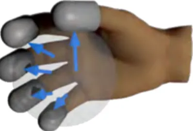
Fig. 1: Concept of the ThimbleSense digit-wearable tactile sensor.
(a) Grasping a ball. (b) Reconstruction.
1
Measuring the hand
Several works address measurement and estimation of posture (see for example [2]-[3]); however, force related measurements provide a greater challenge, especially when the goal is to obtain complete information regarding both force and torque. This is often achieved by using sensorized objects [4], that can either compel grasping from predetermined locations, as in [5], or leave the possibility of a more generic grasping configuration, as in [6], even if this sometimes comes at the cost of sacrificing the number of possible contacts between the hand and the object.
An alternative approach consists in applying sensors directly on the hand, to favor versatility: this can be accomplished by using gloves (see [7] for some examples) which, however, usually use pressure sensors, and thus do not provide any information regarding shear forces. More advanced approaches exist that measure forces while leaving the finger pad free from occlusion: in [8] the relationship between nail strain and compression forces on the finger pad was studied, while in [9] the horizontal deformation of finger pads was used to estimate normal forces. In [10] fingernail sensors were introduced that correlate blood distribution under the finger nail with forces, which later publications further developed and refined (see for example [11]). This last solution is particularly interesting since it also provides measurements for shear forces: however, it requires fine calibration, and currently provides no method to obtain the position of contact points.
This is the context that leads to the concept of ThimbleSense, a design for a fingertip-wearable sensor system which gives complete measurement of all components of generalized forces applied upon grasped objects. This is achieved by combining a commercial six axis force/torque sensor with a pair of support shells, blending the two conventional approaches by building a wearable sensorized object.
2
Concept
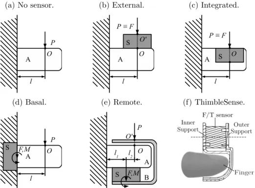
It is possible to cast measurement of forces and torques on a fingertip as a generic structural mechanics problem. To try and analyze the possible solutions, let us abstract from the physical problem at state, and consider the simple 2D example shown in Fig. 3a. A rigid body A, attached to a frame, withstands a force P applied on a point O at position l, perpendicularly with respect to its main axis. Let us suppose that a sensor S is available that is able to measure force F and torque M applied on its surface.
The simplest course of action to measure the applied force is interjecting the sensor between the applied force and the object A, as in fig. 3b. This solution, which is in general possible only when the position l is known a-priori, has the disadvantage of dislocating the point in which the
force P is applied from the original O to the remote point O0. This displacement could be recovered
by excavating a hole inside the object A and using it to integrate the sensor (fig. 3c); or it could be removed altogether by splitting the structure in two parts, separating body A from the frame and interposing the sensor between them, as in fig. 3d. This would allow, from the measurements
of force F and torque M , the straightforward reconstruction of P = F and l = MP , and thus of
both the magnitude and position of the contact force. It is worth pointing out that without torque measurement it would not be possible to estimate the position of the contact.
The three approaches exposed so far lead to the design of common sensorized objects, but they can not be applied to a human finger: approaches 3c and 3d are invasive with respect to the finger, while approach 3b is invasive with respect to the grasp itself, owing to the typical dimensions of force/torque sensors. The problem can then be defined as designing a sensor capable of results similar to those obtainable with approach 3d (simultaneous reconstruction of force and contact position), which can be placed on the finger without completely altering the grasp with interposition of a cumbersome object between the finger and the contact. Fig. 3e shows a possible solution: by assembling the sensor S between the object A and a properly designed shell B we obtain a system
(a) No sensor. (b) External. (c) Integrated.
(d) Basal. (e) Remote. (f) ThimbleSense.
Fig. 3: A basic loaded structure (a), possible ways to sense the load (b-e), and the concept behind the shell-based wearable design (f).
which is completely non-invasive to the finger, while also minimizing alteration to the way the load is applied. In this regard it can be noticed that, as in solution 3b, the load is not directly applied
on point O but on a different point O0; however, contrarily to solution 3b, a proper design of the
shell B can substantially contain the distance OO0. This last solution was selected for the device
proposed, leading to the design of fig. 3f.
3
Design and implementation
Six axis F/T sensor ATI nano 17 was chosen to measure forces and torques: all the sensors which were used in the experiments performed for this work had either SI-25-0.25 or SI-50-0.5 calibration (the interested reader is referred to [12] for more details). While the initial rapid prototyping phase used ABS thermoplastic as material, for the definitive design aluminum was chosen because of its high stiffness/weight ratio. To minimize weight and encumbrance of the device, a Finite Element Analysis (FEA) was performed on candidate CAD models of the device, with the aim of finding the minimum values for shells thickness and gap that still guarantee shells separation when they elastically deform under load application. From some basic tests performed by pressing a finger on a high precision scale, reasonable bounds of the forces applied were estimated: an average value for the force was found to be 10 N, while 35 N appeared as a superior limit. This knowledge was used to define various load models, that lead to a final design for which both shells thickness and gap between shells are 1 mm. The result of the design procedure can be seen in Fig. 4, which shows an exploded view of the final CAD model, together with the list of components for a single ThimbleSense. The shells were machined on a CNC machine.
A higher friction coating is necessary to increase friction, preferably with properties that make it similar to a human finger pad. There is more than a feasible choice for such coating: three different solutions have been tested for ThimbleSense. Fig. 5a shows one, which was employed for the first prototypes: nitrile from working gloves can be used to clad the outer shell, creating an interface with
(a) CAD model (exploded view). (b) Components. Number Name 1 6 Screws m2x4 2 6 Dowel pins 2x4 3 ATI Nano 17 4 Inner shell 5 Outer shell
Fig. 4: Shell based wearable device: final design.
(a) Nitrile gloves cladding. (b) Masking paint. (c) Rubber and latex.
Fig. 5: Artificial finger pad solutions.
increased friction and compliance. The main disadvantage of this solution is its thickness, since even under load the nitrile coating is at least 1 mm thick. In Fig. 5b the second solution is shown: a high friction surface can be created by mixing a masking paint with fine grain sand, and applying the mixture over some strong double sided tape. This solution allows to increase friction with a minimal thickness increase; however, the resulting coating does not offer much compliance, and it tends to lose its friction properties over time owing to smoothing from use and dust. The third solution, that more closely reproduces human finger pad properties, is obtained with pressed rubber covered with latex (Fig. 5c). This solution offers compliance together with a friction that is similar to the friction of a human finger pad (this was verified with some ballpark experiments, similarly to what was done in [13]). However, it has worse mechanical resistance respect to the others, and it is more difficult to build. Second and third solutions have been used in the experiments presented in the following sections.
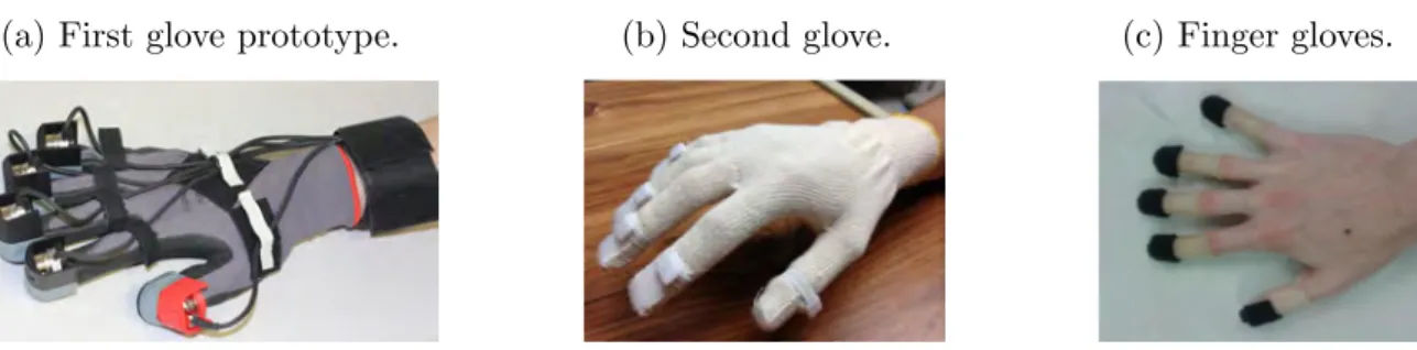
(a) First glove prototype. (b) Second glove. (c) Finger gloves.
Fig. 6: Interfaces used to keep the thimbles on fingertips.
In order to try and minimize the relative movement between ThimbleSense and the hand we use gloves to place the thimbles on fingertips. The coupling can be as simple as gluing the inner thimbles over a glove fingertips for the ABS prototypes (Fig. 6a); however, owing to their higher cost and more complex construction, this is not a practical solution for metal models, for which a
velcro based coupling is used (Fig. 6b). Fig. 6c shows a more advanced solution: tight finger gloves with extremities covered in female velcro work as a second skin over fingers, while male velcro is applied to the inside of the inner shell portion of ThimbleSense. The major drawback of this solution is durability, since the finger gloves tend to break when removed; however, owing to the absence of mechanical slack between finger gloves and fingers, they have been preferred for the last experiment presented in this work, that aims to asses effect of tactile impairment caused by ThimbleSense.
(a) CAD model. (b) Physical realization.
: Fig. 7: ABS support for Phase Space markers.
To complete the device design we also need a way to obtain position and orientation of the thimbles. Position and orientation of a rigid body can be estimated from the position of a number of points attached to it ([14]). Coordinates of points attached to the thimble can be obtained, for example, by using a motion capture system and placing markers on a support attached to the thimble. The current setup uses the Phase Space motion capture system [15], which uses active LED markers that are all uniquely identified by the system through an ID. To make sure that the minimum number of three markers needed to estimate rigid body motion is always available, four marker slots were designed on the support, to be able to tolerate the occasional loss of one marker during the acquisition. Such slots are all placed at different heights over the surface of the support, to maximize visibility. CAD model and physical construction of the support are shown in Fig. 7.
4
Validation: force measurements
The first phase of the validation procedure consisted in verifying the accuracy of force ments provided by ThimbleSense. It was composed of two experiments, both comparing measure-ments from ThimbleSense with the nominal weight of standard weights.
(a) Lower support. (b) Setup with a mass lying on
the upper support.
(c) Force measurement results (static weight validation).
Nominal Measured (average) RMSE 0.49 N 0.49 N 0.004 N 0.98 N 0.97 N 0.009 N 1.96 N 1.93 N 0.034 N 3.92 N 3.93 N 0.008 N 5.89 N 5.85 N 0.038 N
Fig. 8: Static weight validation.
For the first experiment the device was used as a scale, with masses (50, 100, 200, 400 and 600 grams) placed over it with the aid of some supports built in ABS thermoplastic (8a-b), and force
measurements from the sensor were compared for each trial with the expected nominal value of the weight force. Tab. 8c shows a comparison between measured forces and expected nominal values: differences are of the order of 1/100 N.
(a) Setup. (b) Force measurement results (dynamic weight validation).
Nominal Measured (average) RMSE (in N and % of nominal force) 0.49 N 0.48 N 0.024 N (4.9%) 0.98 N 0.95 N 0.064 N (6.5%) 1.96 N 2.02 N 0.091 N (4.6%) 3.92 N 3.88 N 0.12 N (3.1%)
Fig. 9: Dynamic weight validation.
For the second experiment a person was asked to lift masses with index and thumb, while wearing the thimbles, and measured vertical force from the thimbles was compared with the object weight. Masses lifted were 50, 100, 200 and 400 grams. Tab. 9b shows numerical values for the steady-state average measured force: it can be seen that the difference between measured and expected results was at most 6.5% of the nominal value.
5
Validation: contact point estimation
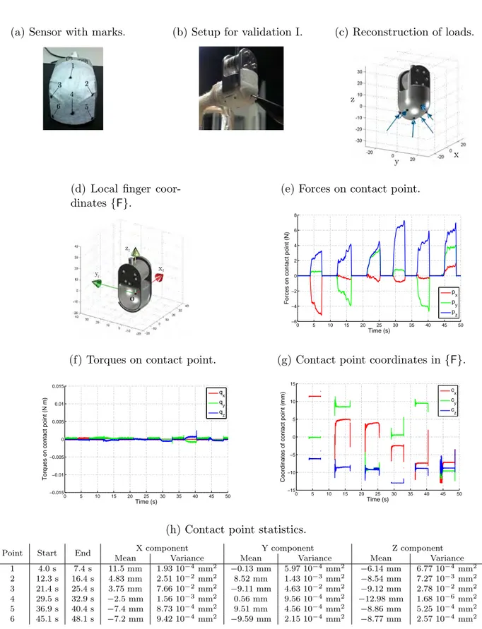
Validation experiments were also performed to asses the accuracy of the implementation of the intrinsic tactile sensing algorithm. The first experiment of this phase was a qualitative validation: some medical tape was applied on the external surface of the fingertip device, with six dots marked, as shown in Fig. 10a. The thimble was then placed on a finger, which was lying on a fixed support (Fig. 10b) and the marked spots were pressed with a pen, in the order shown in Fig. 10a. Fig. 10c shows contact points with forces applied for six samples of time, one for each target. Fig. 10e, 10f and 10g show components for forces and torques applied in the contact point, and contact point coordinates (for the samples where they are available), as expressed in the reference frame {F}. Intervals of time when there is a contact on the sensor surface can be clearly identified in Fig. 10e and 10g: after a short transient, contact point coordinates stabilize to a steady value. The visual feedback from reconstruction in Fig. 10c is realistic: to validate this numerically Tab. 10h shows mean values of all the components, together with variance reconstruction of initiation and termination times of the contact. It can be seen how the contact point estimate is fairly stable once the contact itself is in its steady state.
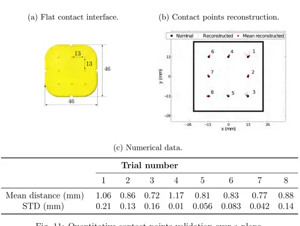
The second experiment quantitatively tested the performance of the intrinsic tactile sensing algorithm. A flat interface (11a) was constructed through rapid prototyping and assembled over an ATI 17 sensor. A number of target points were then pressed and the reconstruction obtained from the intrinsic tactile sensing algorithm was compared with the position known from CAD drawings. Results are shown in Fig.11b and Tab.11c. It can be seen that the estimation error is of the order of the millimeter.
6
Validation with sensorized object
In this section measurements from the wearable device are compared with measurements coming from a sensorized object. The experiment was done with a human subject, and motion tracking
(a) Sensor with marks. (b) Setup for validation I. (c) Reconstruction of loads.
(d) Local finger coor-dinates {F}.
(e) Forces on contact point.
0 5 10 15 20 25 30 35 40 45 50 −6 −4 −2 0 2 4 6 8
Forces on contact point (N)
Time (s) p x p y p z
(f) Torques on contact point.
0 5 10 15 20 25 30 35 40 45 50 −0.015 −0.01 −0.005 0 0.005 0.01 0.015
Torques on contact point (N m)
Time (s) q x q y q z
(g) Contact point coordinates in {F}.
0 5 10 15 20 25 30 35 40 45 50 −15 −10 −5 0 5 10 15
Coordinates of contact point (mm)
Time (s) c x c y cz
(h) Contact point statistics.
Point Start End X component Y component Z component
Mean Variance Mean Variance Mean Variance
1 4.0 s 7.4 s 11.5 mm 1.93 10−4mm2 −0.13 mm 5.97 10−4mm2 −6.14 mm 6.77 10−4 mm2 2 12.3 s 16.4 s 4.83 mm 2.51 10−2mm2 8.52 mm 1.43 10−3mm2 −8.54 mm 7.27 10−3 mm2 3 21.4 s 25.4 s 3.75 mm 7.66 10−2mm2 −9.11 mm 4.63 10−2mm2 −9.12 mm 2.78 10−2 mm2 4 29.5 s 32.9 s −2.5 mm 1.56 10−3mm2 0.56 mm 9.56 10−4mm2 −12.98 mm 1.68 10−6 mm2 5 36.9 s 40.4 s −7.4 mm 8.73 10−4mm2 9.51 mm 4.56 10−4mm2 −8.86 mm 5.25 10−4 mm2 6 45.1 s 48.1 s −7.2 mm 9.42 10−4mm2 −9.59 mm 2.15 10−4mm2 −8.77 mm 2.57 10−4 mm2
Fig. 10: First Validation. All components are expressed in the local finger reference frame shown in Fig. 10d.
(a) Flat contact interface. (b) Contact points reconstruction. (c) Numerical data. Trial number 1 2 3 4 5 6 7 8 Mean distance (mm) 1.06 0.86 0.72 1.17 0.81 0.83 0.77 0.88 STD (mm) 0.21 0.13 0.16 0.01 0.056 0.083 0.042 0.14
Fig. 11: Quantitative contact points validation over a plane.
integration is included. Fig. 12a shows the setup: the sensorized object, which is known to be reliable from previous publication (e.g. [6]), was assembled with a base support to obtain an inverted T, which was then lifted by a subject wearing ThimbleSense on two fingers (for this experiment the fabric glove interface was used, see Fig. 6b). An unbalancing mass was placed on the left side of the object: the task required to lift it while keeping it level, meaning that a compensatory moment needed to be applied to balance the effect of the weight. Since we are not interested in performing an analysis of learning, a bubble level is attached to the inverted T, in order to make the task trivial for the subject. Fig. 12b-d show reconstruction of posture for a sample of time: in Fig. 12b the complete
(a) Grasping setup. (b) Reconstruction. (c) Forces on fingers. (d) Forces on object.
Fig. 12: Experimental Validation III: validation with sensorized object.
grasping setup is reconstructed, while Fig. 12c and Fig. 12d show posture and forces for the wearable device and the sensorized object. A comparison is made on force components tangential and normal to the object, and the compensatory moment required to contrast the action of the weight: normal force is positive when the fingers are pressing against the inverted T, tangential force is positive when
the object is lifted, and the compensatory moment is positive when it contrasts the action of the mass. Differences for total tangential forces (∆Ft), compensatory moments (∆Mc) and contact point coordinates for thumb (∆cTx, ∆cTy and ∆cTz) and index (∆cIx, ∆cIy and ∆cIz) were also calculated (see Tab. 1 for numerical data).
∆Ft ∆Mc ∆cTx ∆cTy ∆cTz ∆cIx ∆cIy ∆cIz
Mean 0.58 N 12.67 N mm 0.28 mm -1.50 mm 1.40 mm -3.05 mm -4.25 mm 2.84 mm
Variance 0.11 N2 193 N2 mm2 0.33 mm2 0.14 mm2 3.52 mm2 1.07 mm2 0.35 mm2 1.63 mm2
Table 1: Numerical data for the validation experiment with inverted T.
7
Tactile Feedback Impairment Evaluation
Experiments presented so far focused on validating the device by proving that measurements were consistent with a ground truth. However, there was another important aspect that needed to be analyzed: when human users wear ThimbleSense a rigid shell is placed on fingertips, thus reducing cutaneous perception and possibly altering the grasping process. In particular, since the tactile feedback from fingertips is distorted, the expected result was an increase of grip forces; however, as subjects used the device and got accustomed to it, it was also expected that they would be able to compensate - at least partially - through learning. This section describes an experiment assessing differences in grasping when wearing ThimbleSense respect to the bare finger condition, and learning influence on the device usage.
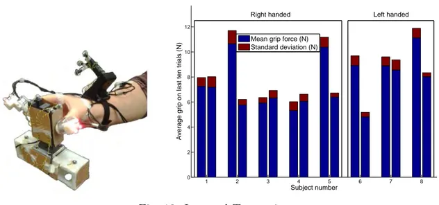
(a) Experiment setup. (b) Average and standard deviation of the mean grip over
the last ten trials, for each subject.
1 2 3 4 5 6 7 8 0 2 4 6 8 10 12 Subject number
Average grip on last ten trials (N)
Right handed Left handed
Mean grip force (N) Standard deviation (N)
Fig. 13: Inverted T experiment.
The same grip device with the inverted T design employed in the previous experiment was used, with 4 LED markers added on the top to allow estimation of position and orientation of the sensorized object. Fig. 13a shows the experimental apparatus: the task consisted in lifting the object using thumb and index of the right hand. In order to have an increased stability respect to the previous experiment, finger gloves were used to place the thimbles on fingers. Experiments were performed at Arizona State University, with protocols approved by the local Office of Research Integrity and Assurance: 8 subjects (age 28.2 ± 2.8, 5 right handed and 3 left handed) were asked to perform the
experiment in two different sessions. All subjects were naive to the use of the thimbles, all had no previous history of orthopedic or neurological pathology or trauma to the upper limbs. During the first session subjects were wearing ThimbleSense devices on thumb and index of their right hand, while for the second session they had to perform the same task with bare fingers. Both sessions had a total of 30 trials, and at least two days were interposed between them. Breaks were allowed at will, and a one minute break was imposed after the 15th trial, to avoid fatigue. Since all subjects kept using the right hand in both conditions, left handed subjects were also accepted for the experiment.
Data analysis focused on evaluating the effect of cutaneous information loss, by comparing steady-state mean grip forces under the two different conditions. Fig. 13b shows a bar plot com-paring the average of the mean grip over the last ten trials under the two different conditions, for every subject. As already observed when comparing the sample plots of mean grip over number of trials, the result was not the same for every subject: the first, third, fourth and seventh subjects had comparable values for the mean grip over the last ten trials in the two conditions, while the other half retained a significantly higher grip force. Moreover, for the subjects that concluded the block with similar grip force values, further analysis showed that they were also not statistically different. This result gives indication of the fact that at least half of the test subjects were able to adapt to the distortion of tactile sensation for what concerns grip force control. For the other half, two possibilities were open: they could have been unable to adapt the force control to the distorted tactile sensation, or they may have been in need of more practice with ThimbleSense to be able to control grip forces properly.
(a) Thimbles on, first block (30 trials).
5 10 15 20 25 30 0 2 4 6 8 10 12 14 16 Trial number
Average grip force
during lift (N)
Thimbles on, first block of trials
Mean grip force for each trial Linear fit 5 10 15 20 25 30 0 0.5 1 1.5
Standard deviation of grip force during lift (N)
Trial number Thimbles on, first block of trials
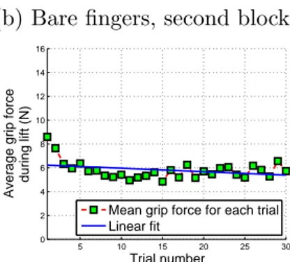
(b) Bare fingers, second block.
5 10 15 20 25 30 0 2 4 6 8 10 12 14 16 Trial number
Average grip force
during lift (N)
Bare fingers
Mean grip force for each trial Linear fit 5 10 15 20 25 30 0 0.5 1 1.5
Standard deviation of grip force during lift (N)
Trial number Bare fingers
(c) Thimbles on, third block (60 trials).
10 20 30 40 50 60 0 2 4 6 8 10 12 14 16 Trial number
Average grip force
during lift (N)
Thimbles on, second block of trials
Mean grip force for each trial Linear fit 5 10 15 20 25 30 0 0.5 1 1.5
Standard deviation of grip force during lift (N)
Trial number Thimbles on, second block of trials
(d) Comparison of the average of the mean grip on the last ten trials.
Thimbles (30 trials) Bare fingers Thimbles (60 trials) 0 2 4 6 8 10 12
Average grip on last ten trials (N)
Mean grip force (N) Standard deviation (N)
Fig. 14: Comparison between the three blocks of trials performed on subject 2.
In order to further investigate this aspect, a third block of trials was proposed to subject number 2, for whom the gap between the final values of grip force in the two conditions was the highest. During this third block the subject was asked to repeat the task while wearing the thimbles, but the number of trials was increased to 60 instead of 30, to provide to the subject more time to adapt. It was desirable for the subject to retain learning relative to the use of the thimbles; however, it was not desirable to have learning that was strictly task-related (i.e. relative to lifted object mass
properties). In order to reduce the effect of task-related learning, this third block was recorded after 11 days had passed between the execution of the second block and the third.
Figs. 14a-c show plots of the mean grip over trials for subject 2, for all three blocks of trials, while Fig. 14d is a bar plot representing the average of mean grip on the last ten trials for each block. The final average value of force, while still higher than the final value of grip force in the bare fingers condition, is considerably smaller than the value that was obtained in the first block. Most importantly, comparing plots for the first (Fig. 14a) and third (Fig. 14c) blocks of trials it can be seen that the grip force decreases more rapidly for this last block. Therefore, there is evidence that the subject was able to learn not only from repetition of trials, but also from previous practice with ThimbleSense (more rapid decrease of grip force respect to the first block, which was carried in the same condition as the third).
8
Conclusions
In this work ThimbleSense, a wearable device that allows to obtain measurements of forces applied during grasping as well as to estimate the position of the contact points, was described. Experimental validations qualitatively and quantitatively showed the accuracy in force measurements and contact point estimation. A validation with a sensorized object was also performed, and the effect of tactile impairment was analyzed, which led to significant indications that such effect can be reduced with training.
Due to its versatility in measuring forces and fingertips position and orientation during grasping of variously shaped objects, ThimbleSense shows promise to be a powerful tool in the field of wearable haptics, to be used for human hand behaviour studies. Ongoing work will involve using ThimbleSense to perform simultaneous measurements of kinematic and dynamic of human hands during grasping of common objects, to evaluate the possibility of building a database of force synergies to augment the currently existing results on posture synergies.
References
[1] A. Bicchi, J. K. Slisbury, and D. L. Brock, “Contact sensing from force measurement,” The International Journal of Robotics Research, no. 12, pp. 249–262, 2001.
[2] M. Bianchi, P. Salaris, A. Turco, N. Carbonaro, and A. Bicchi, “On the use of postural synergies to improve human hand pose reconstruction,” IEEE Haptics Symposium, pp. 91 – 98, 2012. [3] M. Bianchi, P. Salaris, and A. Bicchi, “Synergy based optimal design of hand pose sensing,”
IEEE/RSJ International Conference on Intelligent Robots and Systems, October 7-12 2012. [4] V. M. Zatsiorsky and M. L. Latash, “Multifinger prehension: An overview,” Journal of Motor
Behavior, vol. 40, no. 5, pp. 446–476, 2008.
[5] M. Santello and J. F. Soechting, “Force synergies for multifingered grasping,” Exp Brain Res, vol. 133, pp. 457 – 467, 2000.
[6] W. Zhang, A. M. Gordon, Q. Fu, and M. Santello, “Manipulation after object rotation reveals independent sensorimotor memory representations of digit positions and forces,” The Journal of Neurophysiology, vol. 103, no. 6, pp. 2953 – 2964, 1998.
[7] L. Dipietro, A. M. Sabatini, and P. Dario, “A survey of glove-based systems and their ap-plications,” in Proceedings of the 2008 IEEE Transactions on systems, man and cybernetics, 2008.
[8] N. Sakai and S. Shimawaki, “Strain in the nail at fingertip compression,” Skin Research and Technology, vol. 13, no. 4, pp. 449 – 453, 2007.
[9] M. Nakatani, K. Shiojima, S. Kinoshita, T. Kawasoe, K. Koketsu, and J. Wada, “Wearable contact force sensor system based on fingerpad deformation,” in Proceedings of the 2011 IEEE World Haptics Conference, 2011.
[10] S. Mascaro and H. H. Asada, “Finger posture and shear force measurement using fingernail sensors: Initial experimentation,” in Proceedings of the 2001 IEEE International Conference on Robotics and Automation, 2001.
[11] T. R. Grieve, J. M. Hollerbach, and S. A. Mascaro, “Force prediction by fingernail imaging using active appearance models,” in Proceedings of the 2013 IEEE World Haptics Conference, 2013.
[12] ATI. F/t sensor: Nano17. [Online]. Available: http://www.ati-ia.com/products/ft/ft models. aspx?id=Nano17
[13] G. Baud-Bovy and J. F. Soechting, “Two virtual fingers in the control of the tripod grasp,” Journal of Neurophysiology, vol. 86, no. 2, pp. 604–615, 2001.
[14] D. W. Eggert, A. Lorusso, and R. B. Fisher, “Estimating 3-d rigid body transformations: a comparison of four major algorithms,” Machine Vision and Applications, vol. 9, pp. 272 – 290, 1997.