Politecnico di Milano
Department of Energy - Electrical Engineering Division Doctoral Programme in 2013
Analysis and Realization of a New Device for Power
Quality and Custom Power Improvement: Open UPQC
Doctoral Dissertation of: Hossein Hafezi
Advisor:
Prof. Roberto Sebastiano Faranda Tutor:
Prof. Gabriele D’Antona The Chair of the Doctoral Program: Prof. Gabriele D’Antona
Acknowledgement
First and foremost, I would like to express my gratitude to my supervisor Prof. Roberto
Faranda for his deep insight and useful comments, remarks and engagement through
the learning and research process of my PhD work. The technical background, prac-tical engineering skills and the research experience I have gained under his care will be valuable asset to me in whole my future carrier and life. Form all those I have heard, PhD period was described as up and down working and research experience but working under Prof. Faranda’s supervision I had up and up experience since he has encouraged me always and whenever for any reason I had met him. After each meeting I felt like refreshed, motivated and encouraged to work more and harder. The joy and enthusiasm he had for his research was contagious and motivational for me. He has also provided insightful discussions about the research, his engineering insight was increasable and it has been an honor for me to be his PhD student.
I would like to thank Marco Bugliesi funder of Studio Progettazione Informatica Bugliesi (SpiB.it) company who has been designed and developed controller boards that have been used during the project which my PhD work was a part of it. He has followed most of my laboratory activities and without his support it would be impossible to develop experimental set up in time and properly. I will be grateful forever for all the experiences that I have gained and learned working with him in laboratory but the most impressive point was his character and personality. He is the most polite, patient, flexible and open minded colleague and laboratory mate that I have met ever.
I should be grateful to have a collaboration experience with Prof. Gabriele D’Antona and having his name in my resume. He was the Polimi side responsible of the SDG project which my PhD work was a part of it. He and his research team have carried out several work packages of the project which without their support it would not
be possible to meet the deadlines of the project and also it would not be possible to perform experimental field tests of project.
Without any expectation Prof. Castelli Dezza gave us very big support during hard working days of the project. I think during any project it may come a day when you feel that, it is not going to come true and exactly during those days, Prof. Castelli Dezza gave us very intensive and insightful support. If it came true, Prof. Castelli Dezza has a great impact on it; thanks.
Several experienced and advance research groups have been involved within so called SDG project. Dr. Ermando Ferrari has carried out Raspberry Pi boards pro-gramming and communication task. Eng. Giovanni Accetta as manager, Dr. Davide
Della Giustina, Dr. Giovanni Massa, Eng. Alessio Dedè, Eng. Giuseppe Rino and several
engineers and technicians from Unareti SpA1, Smart Grid Projects Department have been invovled within project and carried out different important and essential work packaged within it. Specially thanks to Unareti SpA enabling the project to be tested in real LV network in Brescia.
European Whirlpool Corporation was another immense partners of the SDG project and several work packages have been conducted with Whirlpool R&D section. In the conjunction of my PhD work I would like to thank Mr. Marco Signa, Eng. Giuseppe
Grauso and Eng. Ettore Arione carrying out experimental tests on shunt units prior to
field test installation.
Power electronic modules are provided by EC&C - Energy Components and Con-sulting S.R.L. Timely delivery, spare parts and technical support services that Eng.
Giovanni Ubezio and Eng. Luigi Ubezio provided during project and in correlation
with my PhD activity were unavoidably crucial in order to successfully finalize the experiment phase of the work.
I gratefully acknowledge the funding sources of the project which was a co-funded project by the Italian Ministry of Economic Development (Ministero dello Sviluppo Economico - MiSE) and it provided a well funded research project and enable us to conduct the work.
Additionally I would like to thanks Prof. Marta Molinas from Norwegian University of Science and Technology (NTNU) who gave me the opportunity to join her research group during my visiting period. Working in NTNU under her supervision has added me a lot of research experiences and helped me to enlarge my research prospective.
I would like to thank Prof. Molinas and Prof. Maria Carmen Falvo reviewing this thesis and for their insightful comments and valuable suggestions which helped me to improve the thesis.
These past Three years have not been an easy ride, both academically and person-ally. Without my beloved life ever partner Neda, I could not be able to overcome the difficulties of this road. she has been a true and great supporter and has ally loved me during my good and bad times. I truly thank Neda for the uncondition-ally love that I feel always and everywhere with her ever presence in my heart.
And finally a very special thanks to my family. Words can not express how grateful I am to my mother-in law, father-in-law, my mother, and father for all of the sacrifices that they have made on my behalf and their endless support during my life.
Hossein Hafezi
Italy - Milano
December - 2016
I dedicate this thesis to my Mother and Father
who have dedicated all their lives growing me up
and teaching me true thinking.
نزنا درام و ردپ به میدقت
منی
نز همه که
د
یگ
.دندکر نم فصر ار ناش
.دوبن نکمم وا قشع نودب که ،ادن منابرهم رس
مه
به میدقت
Abstract
Power Quality (PQ) in Low Voltage (LV) distribution networks is already a concern in many European countries especially where there is a strong presence of renewable energy generation. Therefore there is a growing interest in new solutions able to improve the power quality level of such a system providing regulated power to the end user within standard definition. In other hand, for different reasons, customer may need or require customized power which may not fit into standard definition. PQ and Custom Power may follow the same patch or possibly those may contradict each other going in opposite directions. Therefore, it is not an easy task for Distribution System Operator (DSO) to respect both standard PQ definitions and custom power requirements.
Several solutions have been introduced by electrical power engineers in order to perform PQ compensation tasks and provide custom power requirements. Among those, Uninterruptible Power Supply (UPS) is the most interesting and prosperous solution which is able to provide both PQ and custom power requirements of a cus-tomer. However a UPS system is quite an expensive solution and several alternatives are proposed in order to decrease solution expenses in the cost of reducing its func-tionality and flexibility. Series and Shunt conditioners with different topologies have been studied and those can furnish the grid with their voltage and current compensa-tion capabilities however, a series or shunt condicompensa-tioner alone, is an incomplete solucompensa-tion due to their compensation and service restrictions. To deal with series and shunt con-ditioners shortcomings, a combination of series and shunt conditioner is introduced by Akagi [32] which is able to tackle both voltage and current impureness and it is called Unified Power Quality Conditioner (UPQC).
Although UPQC looks a well designed solution to manage PQ and custom power requirements, however ever increasing renewable energy types, Distributed
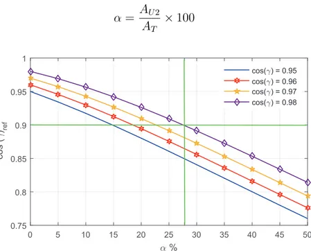
Genera-tion (DG) and storage integraGenera-tion into power system and especially at LV level, have changed the PQ conditioners paradigm into new era. By introducing bidirectional power flow in newly introduced modern and Smart Grid systems, DSOs started to look for system level and modular solutions which are able to operate within this modern and Smart Grid systems communicating with other active participants.
Open Unified Power Quality Conditioner (Open UPQC) [14] is a novel proposal and special design of original UPQC and it is a distributed solution which is able to provide high power quality to the installed area and provide custom power services to the end users and several auxiliary services to the DSO. The proposal is to split the UPQC series and shunt units, move the series unit to the Medium Voltage (MV)/LV substation, in order to support all the installed area, and to split the shunt unit into several units according to end user needs and install each shunt unit at front end of customer property, providing PQ and custom power improvements to the end user and different auxiliary services to the grid and DSO. The series and shunt units are able to communicate with each other within a generic Information and Communica-tions Technology (ICT) system. The proposed Open UPQC is compatible to be easily integrated within Smart Grid systems.
This thesis discusses the working principle, hardware and controller design of Open UPQC. Working philosophy of Open UPQC is explained in detail and series and shunt units responsibilities are introduced. Series unit is meant to work with pure non-active power compensation strategy to inject compensation voltage in quadra-ture to the line current. This working principle is meant to reduce system losses and its realization cost. This non-active power working concept, will impose operation limits on series unit. Series unit operation limits is analyzed in deep, considering pos-sible contribution that shunt units can have to improve series unit performance and this led to the co-operation idea between series and shunt units as happens in the UPQC.
Series and shunt units should be able to work independently so, both units con-troller should be fast enough in order to deal with transient events. Series unit is designed to work as self-supported Dynamic Voltage Restorer (DVR) system in order to compensate both fast and slow voltage variation of the grid. In other hand, shunt unit’s function is like a line interactive UPS system which is able to give some ancillary services to the grid. Beside series and shunt unit local controller, ICT based controller is also described in order to enable co-operation between series and shunt units.
The performance of the designed Open UPQC is verified by MATLAB based sim-ulation and Laboratory experimental tests prior to real field tests. The whole Open UPQC has been realized as a part of Smart Domo Grid (SDG) project and it has been
installed and tested in a real LV distribution network in the city of Brescia, north of Italy.
This thesis presents several original and innovative concepts to the research area. A common solution to answer both PQ and Custom Power issues are investigated. Open UPQC as a unique and innovative distributed solution is proposed to be implemented in distribution LV Smart Grid. Working principle is analyzed in detail and especially series unit operation limits is addressed and continuous operation is verified by simu-lation and experimental tests. Based on best knowledge of author, for first time Open UPQC is realized and the only worldwide available prototype, has been installed and tested in real LV network. PQ and custom power conditioning has been perform in LV distribution network and several scenarios have been defined and tested within Smart Grid system.
keywords:
Power Quality, Custom Power, Smart Grid, Shunt Conditioners, Series Conditioners, UPQC, Open UPQC, LV Distribution, Distributed Generation, Storage, Renewable Energies.
Contents
1 Introduction 1
1.1 Power Quality Standard . . . 1
1.2 Custom Power . . . 6
1.3 Power Quality and Custom Power . . . 7
1.4 Possible Solutions for Power Quality and Custom Power . . . 9
1.4.1 Uninterruptible Power Supply (UPS) System . . . 9
1.4.2 Series Conditioner . . . 11
1.4.3 Shunt Conditioner . . . 12
1.4.4 Combination of Series and Shunt Conditioners . . . 14
1.4.5 Open Unified Power Quality Conditioner (Open UPQC) . . . 16
1.5 Electronic Device in the LV Network (Smart Grid) . . . 21
2 Open UPQC Working Principle 27 2.1 Series Unit . . . 27
2.1.1 Series Unit Operation Limits . . . 32
2.1.2 Series Unit Voltage Rating . . . 37
2.2 Shunt Unit . . . 39
2.2.1 Peak Shaving . . . 40
2.2.2 Reactive Power Compensation . . . 41
2.2.3 Harmonic Current Compensation . . . 42
2.2.4 Transitions, Online to Island and vice versa . . . . 43
2.2.5 Island Operation Mode . . . 44
2.2.6 Shunt Unit Operation Limits . . . 44
2.3 Series and Shunt units Co-operation . . . 45
3 Open UPQC Controller Design 51 3.1 Model Based Inverter current Controller . . . 51
3.1.1 Full Bridge Single Phase Inverter Model . . . 52
3.1.2 Model Based Controller (MBC) . . . 54
3.1.3 Full Bridge Inverter MBC performance . . . 56
3.2.1 Operation Limits Implementation . . . 62
3.2.2 Voltage Reference Generation . . . 64
3.2.3 Series Unit Double Loop Inverter Controller . . . 65
3.2.4 Series Unit Controllers Setting . . . 66
3.3 Shunt Unit Controller . . . 66
3.3.1 Current and Voltage Reference Generation . . . 67
3.3.2 Inverter Control Method . . . 69
3.3.3 DC leg Chopper Control . . . 71
3.3.4 Shunt Unit Controllers Setting . . . 75
3.3.5 Transitions . . . 76
3.4 Series and Shunt Units Co-operation . . . 79
3.4.1 Reference Calculation . . . 79
3.4.2 ICT Based Controller . . . 83
4 Smart Domo Grid and Test Field Demonstration 85 4.1 Smart Domo Grid Project . . . 85
4.1.1 General Description of the Project . . . 86
4.1.2 Project Action Places . . . 88
4.2 Test Network Description . . . 93
4.2.1 Test Field Power Quality Analysis . . . 95
4.2.2 Load Distribution Analysis . . . 98
5 Open UPQC Hardware Design 101 5.1 Series Unit . . . 102
5.1.1 Coupling Transformer . . . 103
5.1.2 Series unit Inverter . . . 105
5.1.3 DC Bus Pre-Charge Circuit . . . 110
5.1.4 Microcontroller and its Power Supply . . . 111
5.1.5 Internet based Communication . . . 111
5.1.6 Bypass Circuit . . . 112
5.1.7 Series Unit Design Parameters . . . 114
5.2 Shunt Unit . . . 116
5.2.1 Static Switch (SS) . . . . 117
5.2.2 Shunt Unit Inverter . . . 118
5.2.3 DC Bus Pre-charge Circuit . . . 122
5.2.4 Chopper Leg . . . 123
5.2.5 Battery Set . . . 126
5.2.6 Microcontroller and its Power Supply . . . 128
5.2.7 Internet based Communication . . . 129
5.2.8 Connection Plug and Bypass . . . 129
5.2.9 Shunt Unit Design Parameters . . . 130
6 Simulation and Experimental Results 135 6.1 Series Unit . . . 136
6.1.1 Over Voltage - Compensation . . . 136
6.1.2 Under Voltage - Compensation . . . 141
6.1.4 Operation Limits and Vref Update . . . 154
6.1.5 Field Record - Series Unit . . . 160
6.2 Shunt Unit . . . 161
6.2.1 Online - No load No Charging . . . 162
6.2.2 Online - Charging the Storage . . . 163
6.2.3 Online - Peak Shaving . . . 165
6.2.4 Online - Load Reactive Power Compensation . . . 166
6.2.5 Online - Load Harmonic Compensation . . . 167
6.2.6 Online - Reactive Power Generation . . . 169
6.2.7 Transition - Online to Island . . . 170
6.2.8 Transition - Island to Online . . . . 171
6.2.9 Island - Noload . . . 173
6.2.10 Island - Under Load . . . 173
6.2.11 Island - Load Variation . . . 174
6.2.12 Field Record - Shunt Unit . . . 178
6.3 Co-operation . . . 179
6.3.1 Decrease Feeder Losses . . . 180
6.3.2 Increase Series unit Over Voltage Compensation Limits . . . 181
6.3.3 Increase Series Unit Under Voltage Compensation Limits . . . . 182
7 Discussions and Conclusions 187
8 Future Works and Studies 191
Bibliography 193
List of Figures
1.1 Power Quality and Custom Power regions representation. . . 5
1.2 Schematic of a double conversion online UPS system. . . 10
1.3 Schematic of a Dynamic Voltage Conditioner (DVC) system. . . 12
1.4 Generic schema of shunt connected conditioner. . . 13
1.5 Generic schema of STATCOM and APF. . . 14
1.6 Schematic of basic series and shunt elements as power conditioner. . . 15
1.7 Generic schema of series and shunt conditioners as UPQC. . . 16
1.8 Simplified schematic of the Open UPQC system. . . 18
1.9 Simplified traditional grid system structure. . . 21
1.10 Simplified Smart Grid system structure integrated in distribution level. 24 2.1 Open UPQC Series unit system model with ideal voltage source. . . 28
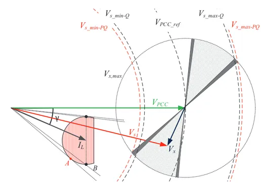
2.2 Open UPQC series unit reactive operation principle. . . 29
2.3 Open UPQC series unit frequency deviation problem during under volt-age. . . 30
2.4 Open UPQC series unit (a) frequency variation during under voltage transient (b) rms voltages. . . 31
2.5 Open UPQC series unit frequency deviation problem during over voltage. 31 2.6 Open UPQC series unit (a) frequency variation during over voltage transient (b) rms voltages. . . 32
2.7 Open UPQC series unit operation, voltage compensation limits. . . 33
2.8 Maximum Vsvariation versus inverter rating voltage and γ variation. . 34
2.9 Maximum Vsvariation versus γ variation with fixed Vx,max. . . 34
2.10 Minimum Vs variation versus inverter rating voltage and γ variation. . 36
2.11 Minimum Vs variation versus γ variation with fixed Vx,max. . . 36
2.12 Vs,maxvariation versus Vx,maxfor different fixed load power factors. . . 38
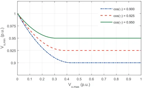
2.13 Vs,minvariation versus Vx,maxfor different fixed load power factors. . . 38
2.14 Open UPQC selected shunt unit system model with ideal current source. 39 2.15 Open UPQC shunt unit peak shaving function. . . 41
2.16 Open UPQC shunt unit reactive power compensation function. . . 42
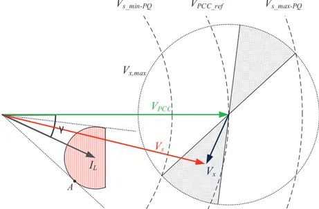
2.18 Open UPQC shunt unit working regions. . . 44 2.19 Open UPQC system model with ideal voltage and current sources. . . . 45 2.20 Vector representation of series and shunt units limits for co-operation. 46 2.21 Effect of active and reactive injection by shunt unit on co-operation mean. 47 2.22 Vector representation of series and shunt units co-operation. . . 48 2.23 Reference power factor variation versus α increment for different loads. 49 3.1 Single phase full bridge inverter schematic. . . 52 3.2 Normal operation current error for three different controllers. . . 55 3.3 Simulation schema - grid connected single phase inverter. . . 56 3.4 Simulation - single phase inverter Model Based Controller (MBC)
per-formance on current step change. . . 57 3.5 Simulation - single phase inverter MBC performance on current ramp
change. . . 57 3.6 Simulation schema - single phase inverter as voltage source, (a) Island
operation mode (b) series connected configuration. . . 58 3.7 Simulation - single phase inverter works as voltage source in island
mode, MBC performance on load current step change. . . 59 3.8 Simulation - single phase inverter works as voltage source in series
con-nected configuration, MBC performance on load current step change. . 59 3.9 Open UPQC series unit single-phase configuration. . . 61 3.10 Open UPQC series unit PCC reference voltage update flowchart for Vx
calculation. . . 63 3.11 Open UPQC series unit reference voltage generation block diagram. . . 64 3.12 Open UPQC series unit double loop controller. . . 65 3.13 Reference current generation algorithm for shunt unit Online operation
mode. . . 68 3.14 Shunt unit Online operation mode controller block diagram. . . . 69 3.15 Shunt unit island mode controller block diagram—PI-MBC, inverter. . . 70 3.16 Shunt unit complete schema with inverter and chopper leg. . . 71 3.17 Lead acid battery charging procedure. . . 73 3.18 Constant voltage chopper charging controller—PI-MBC, chopper. . . . 74 3.19 Chopper Discharging controller. . . 75 3.20 Time detection delay with different p.u. value of main voltage, in mobile
window acquisition case. (the minimum detection time is equal to 0.05ms). 77 3.21 Shunt unit Online to Island transition example. . . 77 3.22 An example of shunt unit magnitude and phase synchronization for
Island to Online transition. . . 78 3.23 Open UPQC system model with ideal voltage and current sources. . . . 80 3.24 Open UPQC ICT based Var controller block diagram. . . 83 4.1 Overview of the Smart Domo Grid project, the old existed network. . . 87 4.2 Overview of the Smart Domo Grid project, the new ICT based project
network. . . 87 4.3 Interactive costumer receives economical offers from DSO through GUI
iPad. . . 89 4.4 Screen shot of the Open UPQC shunt unit test commander consul. . . . 90
4.5 SDG project, Smart MV/LV Substation with Secondary Transformer
Substation (STS) and LV breakers inside. . . 92
4.6 Simplified scheme of the architecture of the project. Data flows for the coordinated regulation actions were depicted. . . 93
4.7 Scheme of the Open UPQC test network - SDG project. . . 94
4.8 Scheme of feeder 7 of the Open UPQC test network - SDG project. . . . 94
4.9 Distribution of voltage dips in the city of Brescia. Data refer to the whole year 2014. . . 95
4.10 RMS voltage measured on the secondary side of the MV/LV transformer (two samples per min). Data refers to six days 30thJune-3rdJuly 2015. . 96
4.11 Voltage trend in three different nodes of the LV grid (six samples per hour). Data refers to six days 5-11thJan., 2015. . . . 97
4.12 Daily mean of domestic customer’s load profile – July 2011. . . 97
4.13 Delivered energy per year as a function of power peak consumption of LV customers. . . 98
5.1 Open UPQC series unit three phase design schema. . . 102
5.2 Open UPQC series unit Coupling Transformer within the whole system. 104 5.3 Open UPQC series unit Inverter connected to the secondary of the cou-pling transformer. . . 105
5.4 Open UPQC series unit capacitor bank (CB), one module realization. . 107
5.5 Cf low-pass filter equivalent circuit. . . 109
5.6 Series unit passive low-pass filter Bode diagram. . . 110
5.7 Series unit DC bus Pre-Charge circuit schema. . . 111
5.8 Series unit Microcontroller and its power supply. . . 111
5.9 Communication between series unit through IEC 61850 protocol. . . . 112
5.10 Open UPQC series unit bypass switch design, power circuit connection. 113 5.11 Open UPQC series unit bypass switch design, (a) control circuit, (b) electrical connection. . . 113
5.12 Open UPQC series unit single phase schema. . . 115
5.13 Open UPQC series unit single phase realized unit. . . 116
5.14 Open UPQC shunt unit Static Switch connection schema. . . 118
5.15 Open UPQC shunt unit inverter schema. . . 119
5.16 Open UPQC shunt unit inverter DC bus capacitor realization. . . 120
5.17 Shunt unit low-pass filter Bode diagram. . . 122
5.18 Shunt unit DC bus Pre-Charge circuit schema. . . 123
5.19 Shunt unit inverter with chopper leg. . . 123
5.20 Shunt unit chopper leg Buck and Boost converter operation modes. . . 124
5.21 Lead-Acid battery Discharging characteristics. . . 127
5.22 Shunt unit battery set connection. . . 127
5.23 Shunt unit Microcontroller power supply circuit. . . 128
5.24 Shunt unit connection plug schema and realized unit. . . 130
5.25 Open UPQC shunt unit single phase schema. . . 131
5.26 Open UPQC Shunt unit single phase realized unit. . . 132
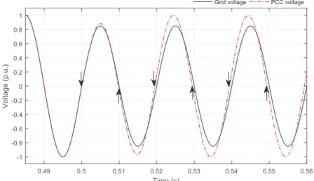
6.2 Simulation - series unit over voltage compensation, transient during starting of 10% over voltage event. . . 137 6.3 Simulation - series unit over voltage compensation, long term (a) grid
side and Point of Common Coupling (PCC) voltages, (b) series unit in-jected voltage. . . 138 6.4 Simulation - series unit over voltage compensation, DC bus voltage
re-sponse to 10% over voltage event. . . 139 6.5 Simulation - series unit over voltage compensation, series unit active
and reactive power exchange during 10% over voltage event. . . 139 6.6 Experimental - series unit over voltage compensation, transient during
starting of 10% over voltage event. . . 140 6.7 Experimental - series unit over voltage compensation, long term, (a)
grid side and PCC voltages, (b) series unit injected voltage. . . 141 6.8 Experimental - series unit over voltage compensation, DC bus voltage
response during 10% over voltage event. . . 142 6.9 Simulation - series unit under voltage compensation, transient during
starting of 10% under voltage event. . . 143 6.10 Simulation - series unit under voltage compensation, long term, (a) grid
side and PCC voltages, (b) series unit injected voltage. . . 143 6.11 Simulation - series unit under voltage compensation, DC bus voltage
response during 10% under voltage event. . . 144 6.12 Simulation - series unit under voltage compensation, series unit active
and reactive power exchange during 10% under voltage event. . . 145 6.13 Experimental - series unit under voltage compensation, transient
dur-ing startdur-ing of 10% under voltage event. . . 145 6.14 Experimental - series unit under voltage compensation, long term, (a)
grid side and PCC voltages, (b) series unit injected voltage. . . 146 6.15 Experimental - series unit under voltage compensation, DC bus voltage
response during 10% under voltage event. . . 147 6.16 Simulation - series unit response to load variation, over voltage case,
adding the load – (a) PCC voltage, (b) series unit injected voltage, (c) load current. . . 149 6.17 Simulation - series unit response to load variation, over voltage case,
removing the load – (a) PCC voltage, (b) series unit injected voltage, (c) load current. . . 150 6.18 Simulation - series unit response to load variation, under voltage case,
adding the load – (a) PCC voltage, (b) series unit injected voltage, (c) load current. . . 151 6.19 Simulation - series unit response to load variation, under voltage case,
removing the load – (a) PCC voltage, (b) series unit injected voltage, (c) load current. . . 152 6.20 Experimental - series unit response to load variation, adding the load –
(a) PCC voltage, (b) series unit injected voltage, (c) load current. . . 153 6.21 Experimental - series unit response to load variation, removing the load
6.22 Simulation - series unit operation limit and Vref update demonstration,
over voltage case – (a) grid side voltage, (b) PCC voltage and its refer-ence, (c) series unit injected voltage. . . 156 6.23 Simulation - series unit operation limit and Vref update demonstration,
under voltage case a: limits due to Vx,max – (a) grid side voltage, (b)
PCC voltage and its reference, (c) series unit injected voltage. . . 158 6.24 Simulation - series unit operation limit and Vref update demonstration,
under voltage case b: limits due to γ – (a) grid side voltage, (b) PCC voltage and its reference, (c) load power factor. . . 159 6.25 Field Experiment, May 2016 - Series unit (a) PCC voltage, (b) grid
volt-age, (c) series unit injected voltage. . . 160 6.26 Simulation and Experimental schema - shunt unit Online operation mode. 161 6.27 Experimental - shunt unit Online operation mode, No load No charge
– (a) grid voltage, (b) grid current. (c) shunt unit current. . . 162 6.28 Simulation - shunt unit Online operation mode, battery charge – (a)
grid voltage, (b) grid current, (c) shunt unit current, (d) Battery charge current. . . 164 6.29 Experiment - shunt unit Online operation mode, battery charge, no load
– (a) grid voltage, (b) grid current. . . 165 6.30 Experiment - shunt unit Online operation mode, battery charge with
1kW load – (a) grid voltage, (b) grid current, (c) shunt unit current. . . 166 6.31 Experiment - shunt unit Online operation mode, peak shaving – (a) grid
voltage, (b) grid and load currents, (c) grid and load rms currents. . . . 167 6.32 Simulation - shunt unit Online operation mode, load reactive power
compensation – (a) grid voltage, (b) load current, (c) grid current, (d) shunt unit current. . . 168 6.33 Simulation - shunt unit Online operation mode, load harmonic
compen-sation – (a) grid voltage, (b) load current, (c) grid current, (d) shunt unit current. . . 169 6.34 Experiment - shunt unit Online operation mode, reactive power
injec-tion – (a) grid voltage, (b) grid current, (c) shunt unit current. . . 170 6.35 Shunt unit transition from Online to Island and vice versa, (a) Online,
(b) Island. . . . 171 6.36 Experiment - shunt unit transition, Online to Island – (a) grid/shunt
unit voltage, (b) load current, (c) shunt unit current. . . 172 6.37 Experiment - shunt unit transition, Island to Online – (a) shunt unit/grid
voltage, (b) load current, (c) shunt unit current. . . 173 6.38 Experiment - shunt unit Island operation mode, no load. . . . 174 6.39 Experiment - shunt unit Island operation mode, 1kW load – (a) shunt
unit voltage, (b) shunt unit current. . . 174 6.40 Simulation - shunt unit Island operation mode, 1.5kW step load change
– (a) shunt unit voltage, (b) load current, (c) shunt unit current. . . 175 6.41 Simulation - shunt unit Island operation mode, DC bus voltage response
on 1.5kW step load change. . . 176 6.42 Experiment - shunt unit Island operation mode, 1.5kW step load change
6.43 Experiment - shunt unit Island operation mode, DC bus voltage re-sponse on 1.5kW step load change. . . 177 6.44 Field Experiment, Feb. 2015 - shunt unit (a) active power, (b) reactive
power, (c) storage State of Charge (SoC). . . 178 6.45 Simplified field demonstration - Feeder 7, Phase B schema where Open
UPQC series and shunt units are installed. . . 179 6.46 Simulation - Open UPQC series and shunt units co-operation, installed
feeder loss reduction demonstration – (a) loss reduction, (b) power factor. 180 6.47 Simulation - Open UPQC series and shunt units co-operation, over
volt-age compensation limit increment by means of co-operation – (a) over voltage compensation percentage, (b) power factor. . . 182 6.48 Simulation - Open UPQC series and shunt units co-operation, under
voltage compensation limit increment by means of co-operation – (a) under voltage compensation percentage, (b) power factor. . . 183 6.49 Simulation - series unit under voltage compensation performance
with-out co-operation – (a) PCC voltage, (b) grid voltage, (c) series unit in-jected voltage, (d) load voltages. . . 184 6.50 Simulation - series unit under voltage compensation performance with
co-operation – (a) PCC voltage, (b) grid voltage, (c) series unit injected voltage, (d) load voltages. . . 185
List of Tables
1.1 Power Quality phenomena according to EN 50160 and IEEE 1159
stan-dards. . . 2
1.2 Voltage distortion limits as expressed by IEEE std 519. . . 3
1.3 Individual harmonic order (up to 25) voltage values at PCC in percent-age of fundamental voltpercent-age, defined by EN 50160. . . 4
1.4 Current distortion limits for systems rated 120 V through 69 kV as ex-pressed by IEEE std 519. . . 4
1.5 Voltage dip distribution as expressed by EN 50160. . . 5
1.6 Available solutions for PQ and custom power according to [3]. . . 8
1.7 UPS summary on PQ conditioning and its performance. . . 11
1.8 Series conditioner summary on PQ actions and its performance. . . 12
1.9 Shunt conditioners summary on PQ actions and their performance. . . 14
1.10 Combination of series and shunt conditioners, summary on PQ actions and their performance. . . 16
1.11 Open UPQC summary on PQ actions and its performance. . . 20
1.12 Brief comparison between the traditional grid and the Smart Grid [31]. 23 3.1 Series unit controllers parameters. . . 66
3.2 Shunt unit controller parameters. . . 75
4.1 Minimum, maximum, mean values, jitter and standard deviation of the voltage measured in the test area, grouped per feeder and per phase. . 96
4.2 Possible energy saving by Open UPQC shunt unit application in LV customers. . . 99
5.1 Series unit communication data and command signal list. . . 112
5.2 Single-phase series unit components parameters. . . 115
5.3 Shunt unit communication data and commands list. . . 129
5.4 Shunt unit connection plug description. . . 130
CHAPTER
1
Introduction
Power Quality and Custom Power are two different terms in electric power system.
PQ is the definition of a unique standard which the system operators should respect precisely. However the custom needs can be not satisfied respecting this standard. Custom Power requirements in some senses could be in contrary with standard PQ definition and in some cases these two area could find common needs and challenges. This chapter presents PQ standard definition and limits for LV system and later it talks about commonly used custom power definition and requirements in order to find out where these two area can be along each other. In so doing, the chapter discusses pos-sible PQ and custom power solutions. Finally the proposed Open UPQC is introduced and described in detail. The necessity of electronic device is investigated as well and the concept of Smart Grid is explained.
1.1
Power Quality StandardNowadays in power systems the PQ is an important topic from several point of views. Improving the PQ in an electrical grid, will decrease the system losses and increase transmission and distribution systems capability. So, the standard defines appropriate working condition where the grid and electrical equipments of user can work properly. Standard gives the minimum boundary limits on different power quality phenomena. These International and National Regulations require DSOs to monitor PQ and to appropriately intervene in order to deliver energy to customers characterized by these
quality levels maintained within appropriate ranges. In order to define PQ limits, the IEEE 1159 [2] and European standard EN 50160 [58], have been taken as reference in this thesis. Two standards in principle are the same in their fundamental how-ever, in some detail there are some small differences and for those cases both standard considerations are addressed. From the system provider point of view, the EN 50160 gives limits on supply voltage and concerning this standard, voltage PQ phenomena can be classified in: Transients; Short-duration Root Mean Square (RMS) variations; Long duration RMS variations; Interruption; Imbalance; Waveform distortion; Voltage fluctuations and Power frequency variations.
Standard defines the normal operation voltage within 0.9-1.1 p.u., where the per unit should be calculated referring to the standard phase to neutral nominal voltage,
Vnand for European LV network standard defines it as; Vn=230 V. According to this
PQ definition,±10% variation is allowed within distribution LV network. As a mater of the frequency, the system frequency should be kept within 50 Hz±10% limit dur-ing 99.5% time of a year. The frequency variation is much more rigid than voltage amplitude because frequency variation can have severe effect on the equipments and also make the power system unstable. The imbalance factor shall be less than 2% for LV network. According to the IEEE 1159, the imbalance factor is defined as the per-centage of voltage negative sequence over its positive sequence, %Imbalance = |Vneg|
|Vpos|. Outside theses conditions the system is out of PQ standard and the DSO need to make proper intervention in order to compensate the PQ problems and move the system inside the standard. Common PQ phenomena are addressed in Table 1.1.
Spectra Duration Magnitude range
Transients kHz-MHz ms - µs 0-4 p.u.
Short duration rms variation
(sag/swell)
– 0.5-30 cycle 0.1-0.9 p.u. & 1.1-1.4 p.u. Table 1.5
Long duration rms variation
– > 1 min 0.8-0.9 p.u. & 1.1-1.2 p.u.
Power frequency variation
– < 10 s ± 0.50 Hz
Imbalance – steady state > 2%
Table 1.1: Power Quality phenomena according to EN 50160 and IEEE 1159 standards.
Managing harmonics in a power system is considered a joint responsibility involv-ing both end users and system owners or operators so, harmonic limits are recom-mended for both voltages and currents. Harmonic voltage distortion limits are pro-vided to reduce the potential negative effects on user and system equipment. The lim-its according to IEEE recommended standard are reported in Table 1.2. These steady-state limits on system voltage and current Total Demand Distortion (TDD) and Total
Harmonic Distortion (THD) are extensively explained in IEEE recommended standard [4]. TheTDD and THD definitions are addressed as well. It concerns quality of power that is to be provided at the PCC, where the PCC, as it is described in standard, "is
usually taken as the point in the power system closest to the user where the system owner or operator could offer service to another user". Voltage and current harmonics has
cou-pling effect on each other, end users produce harmonic currents that flow through the system which lead to voltage harmonics in the voltages supplied to other users and harmonics on supply voltage can exacerbate current distortion [36].
Therefore, connecting a load with high harmonic distortion factor will propagate harmonics into the system and affect neighbor user’s current and voltage profile. So, the standard defines two different restrictions; one the characteristic of the supply voltage at PCC and second is the limits on the connected load current characteristic. The limits are defined for THD and also the limits for each individual harmonic order magnitude. The limits are shown in Table 1.2, generally for LV system the voltage THD level should be less than 8% however, the standard defines limits on each individual harmonic as well. Table 1.2 is completed with Table 1.3 where detail consideration on each individual harmonic order is shown up to 25thharmonic order according to
standard because the magnitude of higher order are usually very small although some standards give limits for higher orders as well.
Bus voltage V at PCC Individual harmonic (%) Total harmonic distortion THD (%) V 6 1.0kV Table 1.3 8.0 1kV < V 6 60kV 3.0 5.0 69kV < V 6 161kV 1.5 2.5 161kV < V 1.0 1.5a a
High-voltage systems can have up to 2.0% THD where the cause is an HVDC terminal whose effects will have attenuated at points in the network where future users may be connected.
Table 1.2: Voltage distortion limits as expressed by IEEE std 519.
Similar limits are defined for current in different voltage ranges. The limits reported in this context is to apply to the users connected to systems where the rated voltage at the PCC is 120 V to 69 kV. According to standard at the PCC, users should limit their harmonic currents as reported in Table 1.4. Where Iscand ILare defined in standard
as:
• Isc =maximum short-circuit current at PCC
• IL=maximum demand load current (fundamental frequency component) at the
PCC under normal load operating conditions
har-Odd harmonics
Even Harmonics
Not multiples of 3 Multiples of 3
order h relative amplitude uh order h relative amplitude uh order h relative amplitude uh 5 6.0 % 3 5.0 % 2 2.0 % 7 5.0 % 9 1.5 % 4 1.0 % 11 3.5 % 15 1.5 % 6 to 24 0.5 % 13 3.0 % 21 0.5 % 17 2.0 % 19 1.5 % 23 1.5 % 25 1.5 %
Table 1.3: Individual harmonic order (up to 25) voltage values at PCC in percentage of fundamental voltage, defined by EN 50160.
monic propagation thorough the network. This harmonic injection affects other users and may flow through their site and damage their equipment. In this case, either its the end user responsibility to limit its harmonic injection through the network or the DSO will intervene harmonic compensation action and charge the user for the com-pensation costs.
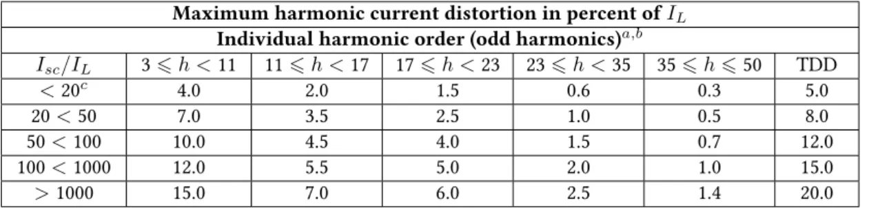
Maximum harmonic current distortion in percent of IL
Individual harmonic order (odd harmonics)a,b
Isc/IL 36 h < 11 116 h < 17 17 6 h < 23 23 6 h < 35 35 6 h 6 50 TDD <20c 4.0 2.0 1.5 0.6 0.3 5.0 20 < 50 7.0 3.5 2.5 1.0 0.5 8.0 50 < 100 10.0 4.5 4.0 1.5 0.7 12.0 100 < 1000 12.0 5.5 5.0 2.0 1.0 15.0 >1000 15.0 7.0 6.0 2.5 1.4 20.0 a
Even harmonics are limited to 25% of the odd harmonic limits above. b
Current distortions that result in a dc offset, e.g., half-wave converters, are not allowed. c
All power generation equipment is limited to these values of current distortion, regardless of actual Isc/IL.
Table 1.4: Current distortion limits for systems rated 120 V through 69 kV as expressed by IEEE std 519.
Concerning PQ, the focus is often on the short-duration RMS variations, also known as voltage dips/swells, since it has the most relevant impact over the Quality of Service (QoS) after voltage interruptions.
EN 50160 standard describes the distribution of dips by considering its duration t and residual voltage u1, proposing the clustering reported in Table 1.5. Each cell of the table contains the number of events. A further contribution to the description of voltage dips is provided by EN 61000-4-11 [59] and EN 61000-4-34 [60], defining the testing and measurement techniques to determine the immunity level of LV connected equipment to voltage dips. Background colors, used in Table 1.5, are the mapping of immunity classes – as defined in [59] and [60] – upon the clustering proposed in [58]:
Event No. t(ms) u (%) 106 t 6200 200< t6500 500< t61000 1000< t65000 5000< t66000 90 > u> 80 80 > u> 70 70 > u> 40 40 > u> 5 5 > u
Table 1.5: Voltage dip distribution as expressed by EN 50160.
• Class 2 including light gray cells;
• Class 3 including dark and light gray cells.
According to the standard definition; Class 2 refers to the PCC and internal PCC (IPCC) in an industrial environment and Class 3 refers to IPCC in an industrial en-vironment. Indeed Class 1 which does not fit in any of the cells in Table 1.5 refers to protected supply systems and its compatibility level is lower than in public supply network and usually highly sensitive loads go within this class and those need extra protection by means of PQ or custom power improvement devices. In this case the load needs a power supply with quality level more rigid or different than the stan-dard one. Figure 1.1 is represents how the PQ and Custom Power defined regions can coincide to each other or the load needs can exceed this limit.
Custom Power C Power Quality
A
B
Figure 1.1: Power Quality and Custom Power regions representation.
The standards define a safe working region for the loads which is shown with green dotted and dashed area (region B) in Figure 1.1. If for any reason the quality of supply voltage at PCC falls below standard limits, for instance as it is shown with green dashed line (region A) in Figure 1.1, it is the DSO responsibility to properly intervene to improve the PQ level of the system and move it inside the standard safe area shown with B. In other hand, an special user may require a power level outside the standard
which is shown in Figure 1.1 as custom power (region C). In this case, it is the end user’s interest to have a supply power and voltage different than what is defined by standard, so the end user will require an specially designed electronic device to comply its needs and also to be able to respect to the standards and be connected to the grid.
1.2
Custom PowerAs it is illustrated in Figure 1.1, sensitive loads may need more rigid power supply and this can stay outside standard PQ definition. Due to different reasons several indus-trial and domestic users require customized electric power or in other world custom power devices at their company or property. Different reasons can be mentioned as why customers want custom power devices however, in most cases the reason origi-nated because the costumers want to save their manufacturing and consumption costs to decrease their energy bills and be more efficient. Some common reasons why cus-tomers require custom power are listed below;
• To manage their energy demand • To maintain their production line
• They require different voltage level than the network one • They require different frequency than the network one • They require variable frequency
• They require flexibility on their own business • They require controllability on their property
• They require monitoring and accessibility on their devices
Usually the companies design and build an especial custom power devices based on the customer requirement and order. Nowadays, power electronics by means of fast turn on/turn off solid-state switches made it possible to modify the broad range of standard off the self power supplies to meet customers specific requirements. As it was mentioned, these customizations are useful and in most cases are essential in sev-eral industrial sites. For instance medical science needs continuity and a power supply with very rigid power quality level so, it is common to have several custom power de-vices in site. Research laboratories and academic works also need customized power supply system to run their tests and research. Several other industry and governmen-tal sectors also require custom power devices.
Therefore, the Custom Power area is very wide and in some cases it is in contrary to PQ standard. So, it is necessary to investigate PQ standards with Custom Power
requirements in order to find possible common working regions to introduce solution which meets both side requirements and limits.
1.3
Power Quality and Custom PowerAlthough principally PQ conditioners and custom power devices have different mis-sions at installation point or network, in most solutions, their topology or task follow the same structure. In most common cases the device component and topology are the same and only the functionality is differ from each other. Consequently, it is pos-sible to design a power electronic device which would be able to carry out both PQ conditioning and power customization task co-operating withing a network.
IEEE 1409 guide, application of power electronics for power quality improvement on distribution systems, explains the custom power and PQ solutions for 1kV through 38kV systems [3]. Although the standard is for the voltage range between 1kV and 38kV systems, however as it is mention on page 7, the LV application is very similar and the guide can be adopted for LV systems as well. Several problems have been explained and different available and possible solutions are discussed in detail. Ta-ble 6 of the standard is reflected as TaTa-ble 1.6 where the availaTa-ble common solutions for power providers and customers are moved to an extra column. This means that the forth column reflects common solutions for both DSO and customers and those solutions can be repeated in second and third columns as well, but to save the space, those are not repeated. Table 1.6 suggests possible solutions for different PQ phenom-ena both at system providers (DSO) side and also customer side. The terminology used in the Table 1.6 is defined in detail inside the standard [3] and it is avoided to be repeated here. The custom side devices are excluded the special requirements, those need very different voltage level or variable frequency range which are very difficult to be matched with DSO side standard. The Table 1.6 is used as conjunction between DSO side solutions and customer side ones.
It can be understood from Table 1.6 that the forth column lists more recent and modern solutions and those work for both PQ and custom power improvement how-ever, considering the second column, the solutions are mostly include modification,
sectionalizing over sizing and designation of the system and those are mostly
Po w er quality phenomena Solutions available to p o w er pr o viders (DSO ) Solutions available to customers Solutions available in common for DSO and customers V oltage sag and sw ells • line reactor • mo dification of pr ote ction scheme , line se ctionalizing • tr ee trimming • “hold-in” coil ridethr ough de vice for mo-tor contactors • constant v oltage (ferr or esonant) trans-former • line conditioner • repr ogramming of contr ols of sensitiv e de vice • v oltage regulator • static or hybrid transfer switch • static series comp ensation • static v oltage regulator • backup stor ed energy system V oltage interruptions • mo dification of pr ote ction scheme , line se ctionalizing • tr ee trimming • coil ridethr ough de vice for motor contac-tors • line conditioner • backup stor ed energy system • static or hybrid transfer switch Impulsiv e and oscillator y transients • high energy surge arr ester • pr einsertion resistors and inductors • synchr onous closing • line conditioner • surge arr ester • line reactor Harmonic distortion • line conditioner • passiv e filters and activ e filters • static shunt comp ensation with har-monic cancellation algorithm Noise • gr ounding and shielding • filter • line conditioner F licker • construction of ne w/upgrade d fe eder • construction of ne w substation • distribution series capacitors • conne ction to bus with higher short-cir cuit capacity • static var comp ensation • static shunt comp ensator (distribu-tion ST A T COM) Pr ote ction of nonlinear load • combination series and shunt com-p ensation T able 1.6: A vailable solutions for PQ and custom p ow er accor ding to [3 ].
Referring to Table 1.6 common solutions for PQ and custom power compensation can be chosen. Concerning PQ improvement and voltage compensation, a suitable solution is a series connected device which can be used in both DSO and customer side.The most popular available current profile conditioning devices are the Shunt connected reactive power and harmonics compensator with or without storage. With storage system those can be considered as UPS like, "backup stored energy system" to supply the system in the case of voltage interruption. For critical and nonlinear loads a combination of series and shunt compensation is a practical suggestion.
Considering the PQ and custom power issues and modern systems in the main power network, for improvement of the PQ in LV electrical network towards the cus-tomer, variety of configuration with electronic interface between network and loads have been introduced to electrical power system [33, 6]. The interest and focus of this work is to explore the solutions those meet custom power and PQ requirements to-gether. Referring to Table 1.6 and [3] available common solutions for PQ and custom power are summarized in next section.
1.4
Possible Solutions for Power Quality and Custom PowerIn order to deal with PQ issues and meet custom power requirements, several power electronics devices have been introduced and studied [33]. In the following a summery on common devices for PQ and custom power are reported.
Based on the problem definition and system configuration, it can be categorized into two generic conditioners; Shunt Conditioner, those connected parallel to the grid and usually in front end of the final load or costumer and Series Conditioner, which is located in series to the line and can be support an area of the network or a single load. Beyond these two generic classification,the most popular and widely used device is UPS system which is capable to protect critical loads or an important line or feeder so, first it will be discussed.
1.4.1 Uninterruptible Power Supply (UPS) System
Among the power electronics devices for PQ and custom power improvement, the widely used and most accepted solution in medical, defense, Telecom and several other industries, without doubt, is UPS systems [34]. Different topologies and configurations have been proposed and practiced for UPS systems so, a UPS system can be considered a series conditioner system if Online UPS is taken into account. In other hand the Line
interactive or Offline UPS systems are categorized as shunt conditioner. The system
equipped with storage system to guarantee power continuity to the load therefore, following the standard [3] it is categorized as backup stored energy system.
The most reliable, popular and widely used configuration, is Online UPS system. The configuration is shown in Figure 1.2, [43]. Principally it is placed between AC source and the load. In this device the main power supply is first converted to DC by converter (1) and then reconverted to AC by means of inverter (2); the battery (3) is connected to DC link through the DC-DC converter (4) and it supplies the system in case of mains failure. The DC-DC converter (4) can be necessary for optimum designation of storage system size and ratio because usually the inverter requires DC link voltage about 1.2 times the peak AC side voltage and without a bidirectional DC-DC converter the battery should be chosen to have the required voltage on its terminal. Practically it is preferred to interface the storage battery to the inverter DC link voltage by means of a bidirectional DC-DC converter.
MAIN ‗ ≈ (1) LOAD (2) (3) (4) ≈ ‗ ‗ ‗
Figure 1.2: Schematic of a double conversion online UPS system.
This device can be inserted between the load and the main power supply and for this reason it makes the double conversion continuously even when the main power supply works normally. An amount of energy of the main supply is absorbed to charge the storage batteries, so the storage system is always ready to start properly. The en-ergy performance of the device is low due to the total losses across the two converters on the way to supply the load.
When a failure in the main supply voltage has occurred, the converter (1) does not supply the DC section anymore, therefore, the load takes its energy from the storage batteries through the inverter (2). The situation does not change until the main voltage returns within nominal limits. This solution is widely used in different areas to protect critical load in work places, laboratories, data centers and etc.
The Online UPS is very interesting solution because it provide variable voltage and also frequency at the load side. In other hand the grid side converter (1), can be designed to set grid side power factor to unity and avoid any disturbances to the grid. Having all these options, the Online UPS is one of the best choices for both system provider aspects and also customer needs.
limited controllability on voltage and on frequency control during normal operation mode because during normal operation mode the voltage and frequency are set by grid and UPS is charging the storage battery and it can work as a shunt connected PQ conditioner. If any severe disturbance is happen in grid side or in the time of voltage interruption, the UPS is ready to take over the load, disconnecting the load from grid. Table 1.7 shows a summary of UPS performance as PQ and custom power conditioner. The statements are done according to "Excellent Very good Good Fair
-Poor" for compensation capability, "Very high - High - Medium - Low" for losses and
cost classification and finally "Yes - NO" to indicate either the system is able to give the continuity option to the load or not.
Voltage PQ Current PQ Continuity Frequency
PQ
Losses cost
Excellent Excellent Yes Very good High Very high
Table 1.7: UPS summary on PQ conditioning and its performance.
1.4.2 Series Conditioner
A series conditioner is connected between the grid and the load. Basically it means to deal with voltage PQ problems towards the supplied area and load. Regarding voltage PQ issues several standards are defined. PQ in Europe refers to the EN 50160 [58] defining the key features of the voltage supplied by public distribution infrastructures to final customers, both in MV and LV. To deal with voltage disturbances, usually a series connected power electronic device is installed in series to the line between the distorted power supply and the load.
Considering the PQ standard and issues on supply voltage, this kind of devices can be a cost effective and suitable solution for DSO rather than the end user because it can be installed at MV level and supply a large area.
Generally speaking, DVC is a well-known series connected power electronics de-vice, able to compensate voltage sags/swells, flickers and long term voltage drifts. It can be considered as a cost effective PQ solution that can support an area. Several com-pensation methods have been introduced and different topologies have been practiced and tested in the real field [53]. Among those, active power injection can be consid-ered as the simplest and most effective method to compensate voltage disturbances, however it needs a large storage system integrated to the DC bus of the inverter. To be able to manage long term voltage compensation and regulation, quadrature to the line current voltage injection is required to decrease the storage system size and sys-tem losses [40]. The device schema is shown in Figure 1.3. DVC is placed series to the line, between grid and the load by means of coupling transformer (1). The inverter
(2) works as voltage source and injects required voltage series to the line. The storage system (3) can be included to the system or alternatively for reactive injection instead of storage system, a set of capacitors can be used.
MAIN
≈
‗
(1)
LOAD
(2)
(3)
Figure 1.3: Schematic of a DVC system.
DVC is a PQ solution to compensate voltage issues and provide regulated voltage to the load. Different functionalities can be defined to the device. So, depend on the topology and the tasks assigned to the DVC, system can perform different functional-ities in the system. With storage system the DVC can support wide range of voltage disturbance compensation, however it will increase the system cost and losses. With-out any storage system, although the initial cost will be decreased but, it necessitates precise control method and it is subjected to compensation limits. Over all, since the system is placed between grid and the load, all the load current passes through it, and this will increase the losses in the system.
Table 1.8 shows a summary of DVC performance as PQ and custom power condi-tioner.
Voltage PQ Current PQ Continuity Frequency
PQ
Losses cost
Excellent Poor NO NO High Medium
Table 1.8: Series conditioner summary on PQ actions and its performance.
1.4.3 Shunt Conditioner
Due to the huge advances in electronic devices and power systems, in todays power grid, frequency deviations rarely happen and in most developed countries even the voltage magnitude is often within standard limit. As a result, it is going to be pretty common that instead of an expensive Online UPS system, the system operators and also end users prefer to have a shunt connected PQ conditioner.
user and usually works as current generator and gives PQ services to the connected point to improve network current profile. It can work as Static Synchronous Compen-sator (STATCOM) and Static Var CompenCompen-sators (SVCs) [36, 37] to compensate reactive power of the load. It can work as Active Power Filter (APF) [61] to compensate load harmonic components and avoid these harmonic components to propagate to the grid and improve system efficiency. To enhance its functionalities and performance a stor-age system can be integrated to the device. With storstor-age system, this solution can be considered as Offline UPS type system [34].
The generic configuration is shown in Figure 1.4; it is comprised of a reversible inverter (1) that is the interface between the main and the DC link, energy storage (2) and a static switch (4). The inverter (1) is able to dispatch the energy produced by the distributed generator to the point of interconnection (3) and supplies the load with a high quality level (in this solution the frequency is fixed by the grid and the conditioner can not regulate the frequency independent from the grid one). Moreover, using a single converter, it is possible to obtain consisting economic benefit. When the main supply is present and voltage value is close to the nominal one, the load takes power from the grid, in this condition the inverter (1) maintains the grid current with a high quality level. When the main supply deviates from nominal voltage value, the static switch opens the circuit in order to avoid the power transferring to the main. In this case the load is supplied by the inverter that takes energy from the storage batteries. This changing to islanding operation mode happens without interruption of load power continuity.
MAIN ≈ ‗ (1) LOAD (2) (3) (4)
Figure 1.4: Generic schema of shunt connected conditioner.
The pro of this device is the high energy performance in the normal operation mode, because only a part of load power is under single conversion. In other hand, the power factor of the main is not controlled and depends on the load and the main voltage.
changed to a popular application and depends on its mission in the system, it can be controlled as STATCOM or APF [7, 8, 9]. The generic schema is shown in figure 1.5 and it is comprised of a reversible inverter (1) which is connected to the PCC (3) and a set of capacitors as DC bus (2).
MAIN ≈ ‗ LOAD (1) (2) (3) C
Figure 1.5: Generic schema of STATCOM and APF.
Since this topology has not any storage, there is no any active power exchange between inverter and the grid despite the small amount of active power that inverter requires to compensate switching losses and keep DC link voltage quite constant on capacitor. This device works as current generator to absorb/inject reactive and har-monic current components to compensate any reactive and harhar-monic components of the load. Although the device cost stays in low level (one inverter and there is no stor-age) and its losses are minor (only one conversion ststor-age), its capabilities are limited.
Table 1.9 shows a summary of shunt conditioners performance as PQ and custom power conditioner. As it can be noticed the shunt conditioners can do nothing about the voltage PQ, instead those have very good performance on current compensation. Some topologies with storage system have the ability to supply the system during volt-age interruption but without storvolt-age system a shunt conditioner lose this capability. Depends on system components the cost level can stay in medium or low level.
Voltage PQ Current PQ Continuity Frequency
PQ
Losses Cost
Poor Excellent/Very good
Yes/NO NO Medium/Low Medium/Low
Table 1.9: Shunt conditioners summary on PQ actions and their performance.
1.4.4 Combination of Series and Shunt Conditioners
Basic configuration for a combination of series and shunt conditioners is shown in Figure 1.6. In this case the series action has been preformed by an passive element, link inductance (1), it also consists of an inverter (2) equipped with storage system (3) and connected to the line in PCC (4). In normal operation, the load is supplied by
grid through coupling inductance, the inverter operates as voltage source to regulate the voltage on PCC although the capability of inverter to regulate PCC voltage is limited due to synchronous connection. In the case of main voltage interruption, the static switch (5) disconnects the system from grid, and the inverter supplies the load dissipating the energy stored in the storage system.
MAIN ≈ ‗ (1) LOAD (2) (3) (5) (4)
Figure 1.6: Schematic of basic series and shunt elements as power conditioner.
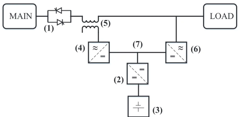
The evolution of the Figure 1.6 configuration can lead to interesting solutions ca-pabale to deal with both voltage and current issues and provide high PQ service to the load. With an active element for both series and shunt actions, the configuration leads to the solution which is shown in Figure 1.7 and it is called UPQC. The generic idea was introduced by Akagi [32]. In this solution a static switch (1), a storage DC-DC converter (2) for a storage system (3) are represented. The UPQC is also provided by two inverters, which one is connected in series (4) with main through a coupling transformer (5) and another one is connected in parallel (6) to the load. The converter (4) behaves as an ideal voltage generator, and the converter (6) behaves as an ideal current generator. In basic UPQC configuration, series converter and shunt converter are sharing common DC link (7). The configuration can include/exclude the storage system. Without storage, the system initial cost is decreased in the cost of losing some functionalities of the device and one of the inverter, either (4) or (6) can be responsible of DC bus regulation. Shunt and Series inverter connections can be swapped. This will change device performance and its functionality [53]. With storage system presence, when a main interruption happens, the static switch (1) disconnects the system in or-der to avoid power flow towards the main, so the load is supplied by parallel inverter (6). Therefore, inverter (6) rating has to be designed according to the nominal power of the load. During island operation mode the series inverter (4) is stalled. During the normal operation mode, when the static switch (1) connects the load to the network, the inverter (4) can absorb the desired active power from the main supply in order to stabilize the DC voltage and stabilize the load voltage while the inverter (6) filters out any impureness of the load current.
MAIN ≈ ‗ (1) LOAD (2) ≈ ‗ ‗ ‗ (4) (5) (6) (7) (3)
Figure 1.7: Generic schema of series and shunt conditioners as UPQC.
Moreover, this configuration allows a high power factor close to the unity and low current harmonic distortion. This solution introduces some amount of losses (in the normal operation mode the power exchange to the load does not convert totally), and a considerable average cost for the converters design. Obviously, as all interactive devices with the network, this configuration is not able to stabilize the load frequency.
Voltage PQ Current PQ Continuity Frequency
PQ
Losses Cost
Very good/Good
Excellent/Fair Yes/NO NO High/Medium Very high/High
Table 1.10: Combination of series and shunt conditioners, summary on PQ actions and their performance.
Table 1.10 summarized the performance of these systems. With active elements as both series and shunt units, those can have very good performance on voltage and current PQ improvement however, a configuration as it is shown in Figure 1.6 has limited capability on voltage and current control actions. With storage system included, a UPQC can provide continuity to the load. The losses and cost of the system is also stays at High and Very high level because the series unit need to pass all the load current. Also shunt unit need to designed according to load nominal power to provide continuity.
1.4.5 Open Unified Power Quality Conditioner (Open UPQC)
For what pertains the PQ improvements as it is summarized, the technology involved is mainly based on power electronics equipment [29, 30] and mostly to increase the functionality and introduce flexibility to the distribution network, a storage system also is integrated to the PQ conditioning device. All the devices and solutions that are introduced, are usually have their own advantages and disadvantages regarding PQ
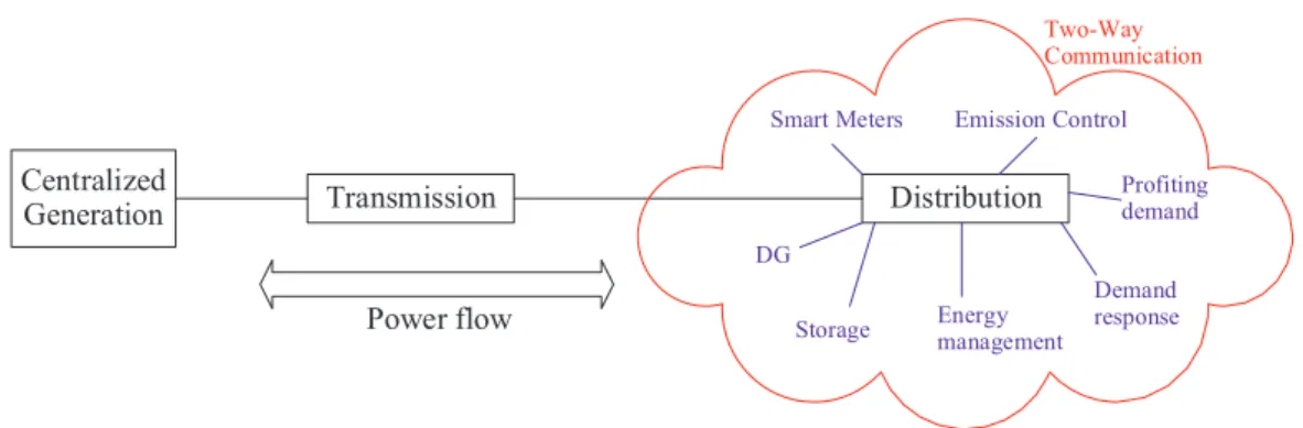
![Table 1.12: Brief comparison between the traditional grid and the Smart Grid [31].](https://thumb-eu.123doks.com/thumbv2/123dokorg/7508619.105008/45.892.223.688.428.690/table-brief-comparison-traditional-grid-smart-grid.webp)