Alma Mater Studiorum – Università di Bologna
DOTTORATO DI RICERCA IN
Ingegneria Elettrotecnica
Ciclo XXVIII
Settore Concorsuale di afferenza: 09/E1 Settore Scientifico disciplinare: ING-IND/31
TITOLO TESI
Superconducting technology for power and energy management
Presentata da: Babak Gholizad
Coordinatore Dottorato
Relatore
Prof. Domenico Casadei
Prof. Antonio Morandi
I dedicate this thesis to my family
and long standing friends for their
constant support and unconditional
love.
A
BSTRACT
In this thesis integration of high temperature superconductor technology in the future advanced power system will be investigated. In particular, superconducting magnetic energy storage system (SMES) for power quality of distribution grid and customer protection will be discussed. The complete design method, including the magnet and power electronic interface design will be discussed in more details. The method will be applied to the design of an industrial scale SMES system. Commercially available high temperature superconductor (HTS) material (YBCO) and magnesium diboride (MgB2) tapes will be considered for the design of the magnet. A
multifunctional control algorithm for compensating voltage sag and improving power quality will be implemented, and the advantages of the SMES system and utilized control algorithm for this application will be illustrated.
As a second part of the thesis, high temperature superconducting DC (HTS-DC) cables for transmission and distribution will be introduced. A method for both electromagnetic and thermo fluid-dynamic design of power cable will be developed. As a first case study superconducting DC collector grid for offshore wind-park will be technically and economically evaluated and the cost and loss model of the system will be discussed. Also, the transient behavior of the high temperature superconducting DC cable in high voltage DC (HVDC) system, which is crucial for stability, will be evaluated. Both line commutated converters (LCC) and voltage source converters (VSC) will be considered.
A
CKNOWLEDGMENT
After finishing a journey, you look back and realize how it changed you, how it helped you grow, and how it helped shape who you are. This has been undoubtedly a magnificent experience which has enriched me both personally and professionally. First of all, I would like to thank to my family in Iran, for all the support and encouragement they provided during all the years of my growth. Without their support I would not have been able to complete my PhD research work successfully. Furthermore, I would like to thank to all my friends in Iran for all the care and support they provided me, regardless the distance, and in spite of their own problems. I would like to express my deepest and sincere gratitude to my advisor Prof. Antonio Morandi for the continuous support of my Ph.D study and research, for his patience, motivation, enthusiasm, and knowledge. His guidance helped me in all the time of my research activity and the writing of this dissertation. His professional supervision and immense technical knowledge have helped my research to steer in the right direction and framed this thesis. His support and guidance have always given me strength to continue forward. All the merits for the results obtained during my research period should be addressed to him. I am looking forward to extend our collaboration also for the future research work. Besides my advisor, I would like to thank the rest of the academic board of the DEI for their kindness, collaborations and willingness to help. My special thanks go to Prof. Rik W. De Doncker director of E.ON Energy Research Center and Institute for Power Generation and Storage Systems (PGS) because of his encouragement and insightful comments during my internship in the RWTH Aachen University Germany. From this university I would like to thank Dr. Ing. Hanno Stagge, Dip. Ing. Nils Soltau, and Dip. Ing. Marco Stieneker for the valuable discussions on the DC networks and Offshore Wind Park collector grid. Also, I would like to thank the rest of the PGS group too. I had very good moments with this group during my internship period. I am very thankful the three years financial support of my PhD by Uinbo scholarship. Also, Marco Polo Grant by DEI for my internship in Germany (2014) is acknowledged. All the friends and colleagues are the subject of my special thanks. Best wishes for your future plans and endeavors. I must declare my joyful life here in Italy. It was a great opportunity to live in such a wonderful country as expected.
T
ABLE OF CONTENT
ABSTRACT ... i
ACKNOWLEDGMENT ... ii
TABLE OF CONTENT... iii
TABLE OF FIGURES ... vi
TABLE OF TABLES ... ix
PART I.SUPERCONDUCTING MAGNETIC ENERGY STORAGE SYSTEM ... 1
1. INTRODUCTION ... 2
1.1. GENERAL SPECIFICATIONS AND APPLICATIONS OF THE ENERGY STORAGE SYSTEM ... 2
1.2. THE ROLE OF THE SMES SYSTEM IN POWER SYSTEM ... 4
1.3. IMPROVED FACTS CONTROLLER:FACTS AND SMES ... 6
1.4. TRANSIENT CONCERNS IN SMES OPERATION ... 7
1.5. REFERENCES ... 7
2. AN OVERVIEW OF SUPERCONDUCTING MAGNETIC ENERGY STORAGE SYSTEMS ... 9
2.1. PRINCIPLES OF OPERATION ... 9
2.2. THE COMPONENTS OF THE SMES ... 10
2.3. DESIGN CONSIDERATIONS ... 13
2.3.1. Coil configuration: Solenoid vs. Toroid ... 13
2.3.2. Conductor ... 15
2.3.3. Energy storage and availability ... 16
2.4. POTENTIAL SMES APPLICATIONS ... 16
2.5. COMPARISON BETWEEN SMES AND OTHER ENERGY STORAGE SYSTEMS ... 17
2.6. REVIEW PAST AND PRESENT STATE OF THE ART OF THE SMES ... 17
2.7. REFERENCES ... 18
3. POWER ELECTRONICS CONVERSION/CONDITIONING AND CONTROL OF THE SMES SYSTEM ... 21
3.1. SEMICONDUCTOR DEVICE TYPES ... 21
3.2. POWER ELECTRONICS CONVERTER TYPES FOR SMES ... 22
3.2.1. Current source inverter ... 23
3.2.2. Voltage source inverter ... 24
3.2.3. Hybrid integration of the SMES with other technologies ... 27
3.3. REFERENCES ... 27
4. SMES COIL DESIGN ... 29
4.1. SUPERCONDUCTING CONDUCTOR AND CABLE ... 29
4.2. ELECTROMAGNETIC DESIGN OF THE SC COIL ... 31
4.2.1. Step one ... 32 4.2.2. Step two... 32 4.2.3. Step three... 34 4.2.4. Step four ... 34 4.3. ACLOSS ... 36 4.4. REFERENCES ... 37
5. SMESCOIL MODELLING ... 39
5.1. POWER SYSTEM TRANSIENTS BRIEF OVERVIEW ... 39
5.2. TRANSIENT CONCERN IN SMES COIL ... 40
5.3. COIL MODEL CONSIDERATION ... 41
5.4. CALCULATION OF ELECTRICAL PARAMETERS FOR A DISK TYPE WINDING ... 41
5.4.2. Capacitance calculation ... 45
5.5. LUMPED PARAMETER MODEL OF THE COIL ... 46
5.5.1. Modeling assumptions ... 46
5.5.2. Modeling steps ... 47
5.5.2.1. Forming inductance matrix ... 48
5.5.2.2. Calculating capacitances for a double pancake ... 49
5.6. REFERENCES ... 50
PART II.HIGH TEMPERATURE SUPERCONDUCTING CABLE ... 51
6. INTRODUCTION ... 52
6.1. REFERENCES ... 53
7. LAYOUT OF THE HTS CABLE ... 56
7.1. COLD DIELECTRIC ... 56
7.2. WARM DIELECTRIC ... 57
7.3. TWO-STAGE COOLING ... 58
7.4. REFERENCES ... 59
8. DESIGN METHODS OF HTS-DC CABLE SYSTEM ... 61
8.1. RADIUS OF THE FORMER ... 62
8.2. THICKNESS OF SUPERCONDUCTOR ... 63
8.3. THICKNESS OF INSULATION ... 65
8.4. THICKNESS OF HTS SHIELD AND COPPER STABILIZER ... 66
8.5. THERMO-HYDRAULIC DESIGN OF THE CRYOPIPE ... 66
8.6. TERMINATIONS ... 70
8.7. TOTAL COOLING POWER ... 70
8.8. REFERENCES ... 71
PART III.APPLICATION OF THE SUPERCONDUCTIVITY IN POWER SYSTEM:CASE STUDIES ... 72
9. MULTIFUNCTIONAL 1MW-5 S SMES SYSTEM ... 73
9.1. MAIN SPECIFICATIONS OF THE SMES SYSTEM ... 73
9.2. SMES COIL DESIGN ... 74
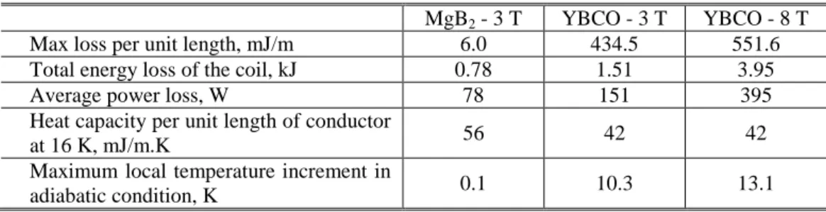
9.3. AC LOSS CALCULATION IN THE COIL ... 76
9.4. ANALYSIS OF TRANSIENT BEHAVIOR OF THE COIL ... 79
9.5. POWER CONDITIONING SYSTEM CONTROL ALGORITHMS AND APPLICATIONS... 80
9.5.1. Control Algorithms ... 83
9.5.1.1. Current Control Algorithm... 83
9.5.1.2. Voltage Control Algorithm ... 85
9.5.1.2.1. Voltage sag detection algorithm ... 85
9.5.1.2.2. Reference voltage calculation ... 86
9.5.2. Design of the power electronic interface of the SMES system ... 87
9.5.3. Applications ... 88
9.5.3.1. Compensation of voltage sag ... 88
9.5.3.2. Load leveling of impulsive or rapidly fluctuating loads ... 88
9.5.3.3. Power factor correction ... 88
9.6. REFERENCES ... 91
10.SUPERCONDUCTING DISTRIBUTION SYSTEM (WIND PARK COLLECTOR SYSTEM) ... 92
10.1. DESCRIPTION OF THE OFFSHORE WIND PARK AND CONNECTION SYSTEM ... 93
10.1.1.Power output of the wind turbines ... 93
10.1.2.Productivity of the wind park... 94
10.1.3.Cluster collector ... 94
10.1.4.Park collector ... 95
10.1.5.Park–to-shore link ... 95
10.1.6.Power-Electronic Converters ... 96
10.3. LOSS CALCULATION ... 100
10.3.1.Losses of AC and DC Copper cables ... 101
10.3.2.Losses of the transformers ... 102
10.3.3.Losses of the converters ... 102
10.3.4.Cooling power of HTS cables ... 103
10.4. COST OF CONVENTIONAL (NON-HTS) COMPONENTS ... 104
10.4.1.Cost of copper cables and transformers ... 104
10.4.2.Cost of the converters ... 104
10.4.3.Cost of the platform ... 105
10.5. COST EVALUATION OF HTS CABLE SYSTEM ... 105
10.6. LOSS AND COST COMPARISON OF WIND PARK CONNECTION SYSTEMS ... 107
10.6.1.Loss comparison ... 107
10.6.2.Cost comparison ... 109
10.7. REFERENCES ... 111
11.TRANSIENT BEHAVIOR OF SUPERCONDUCTING HVDC LINK ... 113
11.1. DESCRIPTION OF THE HVDC TRANSMISSION SYSTEM ... 114
11.1.1.Thyristor based HVDC system ... 114
11.1.2.Voltage source converter based HVDC system ... 114
11.2. CONTROL ALGORITHMS ... 116
11.2.1.Thyristor based HVDC system ... 116
11.2.1.1. Synchronization and firing system ... 116
11.2.1.2. Steady-state V-I characteristic ... 117
11.2.1.3. Voltage dependent current order limiter function ... 118
11.2.1.4. Current, voltage, and gamma regulators ... 119
11.2.2.Voltage source based HVDC system ... 119
11.2.2.1. Outer active and reactive power and voltage loop ... 120
11.2.2.2. Inner current loop ... 121
11.2.2.3. DC Voltage Balance Control ... 122
11.3. CABLE DESIGN ... 123
11.4. MODELING OF THE CABLE IN POWER SYSTEM ... 129
11.5. TRANSIENT BEHAVIOR OF THE CABLE ... 130
11.6. REFERENCES ... 135
T
ABLE OF FIGURES
Figure 1.1 Parameters of the storage system for different applications ... 4
Figure 2.1 Major component of the SMES system (power conversion system can be thyristor base multi-pulse converter, voltage source inverter (VSI) with DC-DC two quadrant chopper, or current source inverter (CSI)) ... 11
Figure 2.2 Solenoid type coil with LN2 reservoir tank ... 14
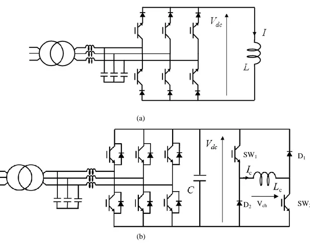
Figure 3.1 Basic concepts of Voltage and source inverter for SMES application, (a) current source inverter (b) voltage source configuration ... 23
Figure 3.2 Simplified voltage signal imposed onto the SMES coil by chopper operating at constant frequency fCH and duty cycle D ... 26
Figure 4.1 Engineering critical current density versus applied field of the MgB2 and the YBCO conductor in the range 16 K – 24 K ... 30
Figure 4.2 Lift factor f() = Je (B,T, ) / Je (B,T, 0) of YBCO conductor ... 31
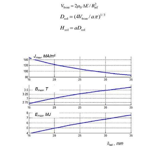
Figure 4.3 Dependence of Jmax, Bmax and Emax on the thickness sol of the solenoid for the 3 T - MgB2 SMES ... 32
Figure 4.4 Length of SC conductor needed for the solenoid as a function of the maximum storable energy Emax for the 3 T - MgB2 SMES... 33
Figure 4.5 Dependence of maximum current Imax (a) and deliverable energy E (b) on the thickness sol of the solenoid and the number N of turns for the 3 T - MgB2 SMES .. 35
Figure 4.6 Curves of constant maximum current Imax and deliverable energy E as a function of the thickness sol of the solenoid and the number N of turns for the 3 T - MgB2 SMES ... 35
Figure 4.7 Current of the SMES during a 5s discharge/5s charge cycle at 1 MW ... 36
Figure 4.8 Distribution of ac loss (J/cycle) within the coil. Values are in Joule. Normalized coordinates are used for expressing the space dependence: r* = (r − Ri)/(Ro − Ri) and z* = z/H ... 37
Figure 5.1 Schematic representation of a winding. Cgi: shunt capacitance, Csi: series capacitance, Li: self-inductance, Mi = mutual inductance ... 42
Figure 5.2 Physical dimensions for the disc type coil ... 43
Figure 5.3 Coil representation by Lyle’s method for b > c ... 45
Figure 5.4 Schematic illustration of capacitive parameters in the entire coil ... 47
Figure 5.5 Derivation of equivalent series capacitance for a double pancake ... 49
Figure 7.1 Layout of the cold dielectric superconducting cable ... 57
Figure 7.2 Layout of the warm dielectric superconducting cable ... 58
Figure 7.3 Layout of the cold dielectric superconducting cable with two stages cooling ... 58
Figure 8.1 Schematic of the HTS cable system. Lcable is the total length of the cable and L is distance between cooling stations ... 62
Figure 8.2 Thermo-hydraulic circuit for the cooling of the HTS cable (CD layout) ... 62
Figure 8.3 Critical engineering critical current density Je of commercial ... 65
Figure 8.4 Examples of isogradient curves for LN2 obtained from equations (8.13)-(8.15) with Di= 30 mm ... 69
Figure 8.5 Choice of the outer diameter and mass flow for a given distance L between the cooling stations ... 69
Figure 9.1 Input power of the cooling system for removal of AC losses versus number of
complete charge/discharge cycles per hour. The maximum number of cycles per hour
is 360 (10 s cycle) ... 79
Figure 9.2 Frequency response of the coil ... 81
Figure 9.3 Power conditioning system ... 82
Figure 9.4 Schematic of the control and the power system ... 82
Figure 9.5 Current control algorithm (a) Control loop of the energy E stored by the superconducting coil (b) Control loop of the voltage Vdc of the DC bus (c) Control loop of the output current of the inverter ... 84
Figure 9.6 Voltage sag detection algorithm, in this figure the details just shown to one of the phases and for other phases the same algorithm is used ... 86
Figure 9.7 Reference voltage calculation for voltage control part of the algorithm ... 87
Figure 9.8 SMES system operation during voltage sag compensation ... 89
Figure 9.9 SMES system operation during load leveling ... 90
Figure 9.10 SMES system operation during power factor correction ... 90
Figure 10.1 Schematic of the offshore wind park and connection system ... 93
Figure 10.2 Productivity of the offshore wind park deduced from weather measurements at Fino 1 research platform ... 94
Figure 10.3 Block diagram of the DAB converter system for DC voltage conversion ... 96
Figure 10.4 Layout of the DC HTS cable ... 97
Figure 10.5 Critical current density of the HTS tape versus applied field parallel to the wide side of the tape ... 98
Figure 10.6 Efficiency of machine-side three-level neutral-point clamped (3L-NPC) converters and dual-active bridge (DAB) converters ... 103
Figure 11.1 Rectifier and inverter steady-state characteristics and voltage dependent current order limiter (VDCOL) function ... 117
Figure 11.2 VDCOL Characteristic; Id_ref f
VdL ... 118Figure 11.3 High Level Block Diagram of the Discrete VSC Controller ... 120
Figure 11.4 DC Voltages and Currents of the Three-Level Bridge ... 122
Figure 11.5 Effect of the distance between cooling stations on cooling energy of the cable ... 124
Figure 11.6 Effect of the distance between cooling stations on the cost of the cable material cost ... 124
Figure 11.7 Effect of the distance between cooling stations on mass flow rate of the LN2... 125
Figure 11.8 Comparison of the XPLE copper based cable and copper base overhead line DC transmission with the HTS-DC cable cost respect to the distance between cooling stations and HTS material cost ... 125
Figure 11.9 Comparison of the XPLE copper based cable and copper base overhead line DC transmission with the HTS-DC cable cost respect to the distance between cooling stations and HTS material cost ... 126
Figure 11.10 Effect of the distance between cooling stations on the cost of the cable material cost ... 127
Figure 11.11 Isogradient curve of the cable for LN2 obtained from equations (8.13)-(8.15) with Rf = 20 mm and L = 20 km... 127
Figure 11.12 Diameters of the cable, red: former of the cable, yellow: electrical insulation, blue: LN2, white: hybrid thermal insulation. Note: the superconducting thickness is too narrow and is not visible in the actual sized figure. ... 128
Figure 11.13 Copper energy loss and the cooling energy respect to the distance between cooling stations ... 129
Figure 11.14 Transient behavior of the HTS cable during different transients in LCC based HVDC system ... 132
Figure 11.16 Transient behavior of the HTS cable during different transients in VSC based HVDC system. ... 134 Figure 11.17 DC side current ripple during normal operation state in VSC based HVDC ... 134
T
ABLE OF TABLES
Table 1.1 Typical stored energy for various power systems applications of SMES (in 1MWh =
3600MJ) ... 6
Table 3.1 Comparison between voltage and current source inverter (VSI and CSI) ... 25
Table 4.1 Main characteristics of the MgB2 conductor ... 30
Table 4.2 Main characteristics of the YBCO coated conductor ... 30
Table 4.3 Input parameters for the design of the SC coil ... 31
Table 5.1 Classification of power system transients ... 39
Table 7.1 Comparison of the characteristics of warm and cold dielectric SC cables ... 59
Table 8.1 Temperature and Pressure limits of the superconducting cable ... 61
Table 8.2 Heat load per unit surface due to radiation (W/m2) through hybrid vacuum + multilayer (30 layers) thermal insulation ... 67
Table 8.3 Average physical properties of LN2 and LH2 in the operating temperatue and pressure range ... 68
Table 8.4 Coefficient of performance of the cooling system ... 71
Table 9.1 Main characteristics of the SMES ... 74
Table 9.2 Main characteristics and designed characteristics of the 1 MW / 5s SMES System .... 75
Table 9.3 AC losses of the 1 MW / 5s SMES System during one discharge – charge cycle ... 78
Table 9.4 Round trip efficiency of the 1 MW - 5 s SMES System during one discharge/charge cycle ... 78
Table 9.5 Parameter of studied coil ... 80
Table 9.6 Lumped coil inductance ... 80
Table 9.7 Parameters of the current and the voltage control algorithm ... 84
Table 10.1 Main characteristics of the HTS tape (YBCO coated conductor) ... 98
Table 10.2 Main characteristics of the DC HTS cables installed within the offshore wind park . 100 Table 10.3 Parameters of the loss model of AC cables ... 101
Table 10.4 Parameters of the loss model of the transformers ... 102
Table 10.5 Parameters of the cost models for AC cables, DC cables and transformers ... 104
Table 10.6 Unit cost of HTS cable materials and cooling system ... 106
Table 10.7 Cost of materials, manufacturing and cooling and overall cost per unit length of DC HTS cables (one pole). All data are in k€/km. Terminations neglected ... 107
Table 10.8 Losses in one year of the Wind Park connection systems (all data are in GWh) ... 108
Table 10.9 Costs of the Wind Park connection systems. A unit cost of 100 €/kAm is assumed for the HTS. All data are in M€ ... 110
Table 10.10 Costs of the Wind Park connection systems. A unit cost of 20 €/kAm is assumed for the HTS. All data are in M€ ... 111
P
ART
I.
S
UPERCONDUCTING
M
AGNETIC
E
NERGY
1. I
NTRODUCTIONThe energy storage system is the key technology for assuring appropriate power quality and for increasing the penetration of renewable sources. Several energy storage technologies exist, each of which offering specific performances. Among these, Superconducting Magnetic Energy Storage (SMES) offers important advantages, including fast response time from standby to full power. The SMES system may not be cost effective currently, but they are attractive because of the positive cost and environmental impact of them through the reduced fuel consumption and emissions [ 1.1]. The advantages of the SMES system can be highlighted as [ 1.2]:
high deliverable power,
virtually infinite number of charge discharge cycles without degradation, and high round trip efficiency.
Due to these characteristics, SMES can find a very wide application as stand-alone storage device or in combination with other storage technology with complementary characteristics (e.g. in hybrid Battery-SMES storage systems [ 1.3]), both at the customer and at the grid level. The SMES was initially envisioned as a large-scale load-leveling device, while the energy storage density of the SMES system is less than the other storage systems, now it is seen mainly as a tool for enhancing system stability, power transfer, and power quality applications. Improving the superconducting and power electronic technologies besides the SMES characteristics and benefits will make the use of SMES more desirable for power utility applications.
1.1. G
ENERAL SPECIFICATIONS AND APPLICATIONS OF THE ENERGY STORAGE SYSTEMAn energy storage system is made up of a storage device, which absorb and store the energy or delivers stored energy to the network with some losses, and a power conditioning system (a set of solid state power converters) which control the power exchange between the electric terminals of the storage device and the grid. Auxiliary devices such as cooling and control, which also they have some losses, are usually needed for the operation of the system. The storage systems have a cyclic operation which includes the charge, discharge and idle work duration (the energy supplied to the grid must be first absorbed from the grid) in power systems. However, it must be considered that in many applications the parameters of the operating cycle (duration, charge and discharge time, possibly idling) changes continuously and randomly [ 1.2].
The main parameters of an energy storage system are
Maximum power (charge/discharge rate) that can be absorbed or supplied, P Duration of the power delivery, t
Response time required for making the maximum power available starting from stand-by, tr
Number of cycles that can be reliably endured during the lifetime, N
The input / output power of the storage system can be fully controlled if the storage system is not discharged below the certain level this limitation is exist because of the intrinsic characteristics of the power conversion / conditioning systems [ 1.2]. The minimum quantity of energy Emin should
always remain in the storage device. If the maximum power P is to be delivered for the interval t the rated energy E of the device can be obtained as:
( 1.1) EEminPt
The efficiency of the storage system in a cycle can be defined as follows [ 1.2]:
( 1.2) cycle aux idle idle c s t P t P t P t P
where s is the round trip efficiency of the storage device (from electricity back to electricity), c is
the efficiency of the converters, Paux is the power required for auxiliary services and Pidle is the
power loss (if any) during the possible idling phase. It is clear from equation ( 1.2) that low auxiliary and idling losses are essential for efficient long term storage (tcycle >> t and tidle >> t).
However the impact of these losses on the efficiency of the energy will be less if the high rate power exchange experience with the storage system over the short cycles [ 1.2].
A total generated power and the load power in the electric system must continuously be in balanced condition. In power system imbalance due to the random fluctuation of loads induced by customers, or due to the variation of generation from non-programmable sources (i.e. renewables), generation/transmission failure occurs. In power system system-wide failure (black out) can occur due to the power imbalance if it is not promptly compensated. Continuous and fast regulation of the generated power (and/or loads) is then required. Load imbalance occurs in a power system on different time scales, from less than one second in case of contingency to minutes following the typical change induced by customers or variable generation. A very large variation of the load occurs at intervals of hours. A potential method for reducing load imbalances and assuring the reliability of the power system is energy storage [ 1.2] and [ 1.4]. Energy storage also allows a more economic planning and exploitation of the generation resources. Furthermore, it can also be used at the customer level for appropriate power quality or for smoothing the power absorption of
impulsive loads. The main specifics of the storage system for each of the applications are indicatively shown in Figure 1.1. Other applications such as damping of sub-synchronous resonance, black start or deferral of new transmission and distribution are also possible, but are likely to have a more limited cost/benefit trade-off. Smart loads and smart grid, beside energy storage, are also emerging as an integrating technology for energy management in the electric power systems [ 1.2]. Furthermore the increase of transmission capacity by means of multi-terminal DC links to exchange generating resources over larger areas is also receiving an increasing attention for the same reason [ 1.5]. Finally, improved controllability of conventional generation can also bring significant contributions [ 1.2].
Figure 1.1 Parameters of the storage system for different applications [ 1.2]
1.2. T
HE ROLE OF THESMES
SYSTEM IN POWER SYSTEMIn 1970s superconducting energy storage system (SMES) was first proposed as technology in power systems. In the SMES energy is stored in the magnetic field which is generated by the circulating DC current in the large inductance, the inductance made by the superconducting coil. A SMES system consists of a superconducting coil, the cryogenic system which provides the cold environment to guarantee the superconductivity in the coil, power conversion or conditioning system (PCS) with control and protection function. Since in the SMES there is no energy conversion from one form to another form the total efficiency of the round trip working of the
SMES system can be very high. However, round trip efficiency of the SMES depends on the idle working time during the round trip operations (see equation ( 1.2)), while the losses due to the idle working time period in power electronic switches and continues cooling requirements will decrease the efficiency of the SMES system; if the duration of the idle working is not so long during the round trip operation of the SMES system, the efficiency of the SMES system can be more than 90% [ 1.2]. Depending on its PCS unit’s control loop and power electronic switches characteristic, the SMES system can respond rapidly (MWs/milliseconds). While there is no moving part in the SMES system, it is reliable and environmentally friendly technology. Compared to other storage technologies, the SMES technology has a unique advantage in two types of applications:
1. power system transmission control and stabilization, and
2. power quality power systems [ 1.1].
Round trip efficiency and faster response capability of the SMES system has been and can be further exploited in different applications in all levels of electric power systems. SMES systems have the capability of providing
load leveling,
frequency support (spinning reserve) during loss of generation, enhancing transient and dynamic stability,
dynamic voltage support (VAR compensation), improving power quality,
increasing transmission line capacity,
thus, overall enhancing security and reliability of power systems
The characteristics of potential SMES applications for generation, transmission, and distribution are given in Table 1.1 and depicted in Figure 1.1.
Among these applications, the ones with power ranges of 20–200 MW and energy ranges of 50– 500 MJ (0.014–0.14 MWh) have been found to be the most cost beneficial applications [ 1.1]. As can be seen from Table 1.1, applications of transmission stability and frequency control are therefore economically attractive. Furthermore, custom power and power quality have also been found to be economically feasible low-power applications for SMES [ 1.1] and [ 1.7].
Also, the SMES can integrate with the flexible AC transmission system (FACTS) controllers to provide energy storage at the transmission level or custom power devices at the distribution level [ 1.6]. Adding significant energy storage capability to the FACTS controllers (e.g. StatCom) allows these devices to provide active power in addition to reactive power; and the number of degrees of the freedom for control purposes will increase to two. Therefore the effectiveness of the outer
power system control function increases, and enhancing system reliability and/or availability will be possible.
Table 1.1. Typical stored energy for various power systems applications of SMES (in 1MWh = 3600MJ) [ 1.1] and [ 1.7]
Application Typical Stored Energy Capacity Typical Discharge Period
Gen
er
atio
n
Load leveling 100 – 5000 Hours
Dynamic Response 80 – 2000 Hours
Spinning Reserve 2 – 300 Minutes
Frequency Control 0.15 – 15 Seconds
T
ran
sm
is
sio
n Load Leveling 10 – 1000 Minutes – Hours
Stabilization 0.002 – 10 Seconds
Voltage/VAR Control 0.0003 – 0.03 Milliseconds (Cycles)
Dis
tr
ib
u
tio
n Load Leveling 0.015 Minutes –Hours
Power Quality 0.00003 – 0.003 Seconds
Custom Power 0.00003 – 0.003 Milliseconds (Cycles)
1.3. I
MPROVEDFACTS
CONTROLLER:
FACTS
ANDSMES
Second generation FACTS controllers are power electronic devices with integrated energy storage that handles both the active and reactive power to enhance the transmission system performance. With the appropriate configuration and control, they can influence the transmission system parameters such as impedance, voltage, and phase angle. FACTS controllers can be connected to the power system in series, parallel or combined form and they can utilize or redirect the available power and energy from the AC system. Without energy storage, they are limited in the degree of freedom and sustained action in which they can help the power grid [ 1.8]. One of the viable energy storage technologies, SMES, can be added to a FACTS controller to significantly improve the control actions of FACTS.
A SMES system requires a PCS that can be either a voltage or current source inverter. Since the inverter utilized for a FACTS controller is voltage source based, it is a logical approach to attach the SMES to a FACTS controller. The integration of a FACTS device with the SMES can provide
independent real and reactive power absorption/injection from/into the grid. The combined system would not only provide better performance than separate stand-alone devices, but it could also have a lower cost since the combined system can generate the same performance with lower ratings. Custom power devices are similar to FACTS devices in topology, but at smaller ratings. Most of the current SMES projects use small-scale or micro SMES devices [ 1.9]-[ 1.11]. They can also be attached to custom power devices to increase the effectiveness of the overall system.
1.4. T
RANSIENT CONCERNS INSMES
OPERATIONThe power electronics applications in power systems continue to increase. Normal and abnormal switching of power electronics devices may generate transient over-voltages. These over-voltages, take place in very short time compared to steady state, but, they may have potential to damage any equipment that is subject to these transients. Therefore, the control and modeling of power electronics devices is an important task in power system transient studies.
A SMES system is comprised of power electronics devices. Switching actions of these devices during charge and discharge may cause serious transient over-voltages. These transients may have potential to damage the coil insulation. The SMES unit may fail simply because the insulation level was not designed to withstand transients. Most of the SMES failures have been experienced due to insulation and protection problems. This is especially more important for large coils [ 1.12]. It is essential to characterize the transients that may be experienced by the SMES coil for insulation and protection purpose. A good analysis of transient interaction between a superconducting coil and its power electronics interface is crucial to avoid any insulation problem that may be experienced.
A detailed model of the coil is necessary to identify the transients better. Breaking down the coil into small pieces, representing the entire coil and analyzing the internal node voltages will give a better understanding of the transients that may affect the coil. A detailed modeling of the superconducting coil along with the power electronics interface modeling and control are essential in the electromagnetic transient interaction analysis.
1.5. R
EFERENCES[ 1.1] S. Eckroad, “Program on Technology Innovation: Modeling of SMES and Its Integration to the Power Grid”, 1012153, EPRI final report December 2006, online available at: http://goo.gl/3A3C2z
[ 1.2] A. Morandi, “5. Power applications – 5.5 Energy Storage (SMES and Flywheels)”, in Applied Superconductivity: Handbook on Devices and Applications, Editor P. Seidel, Weinheim: Wiley-VCH; 2015, pages 660-674,http://dx.doi.org/10.1002/9783527670635
[ 1.3] T. Ise, M. Kita, A. Taguchi, “A hybrid energy storage with a SMES and secondary battery,” IEEE Transactions on Applied Superconductivity, vol.15, no.2, June 2005, pages 1915-1918, DOI: 10.1109/TASC.2005.849333
[ 1.4] P. Denholm, E. Ela, B. Kitby, and M. Milligan “The Role of Energy Storage with Renewable Electricity Generation” NREL report No. TP-6A2-47187, January, 2010, (http://www.nrel.gov/docs/fy10osti/47187.pdf) [ 1.5] P. Fairley, “HVDC Supergrid Technologies Besting Expectations,” IEEE Spectrum, March, 2013, online
available at: http://goo.gl/fU4c4y
[ 1.6] A. Arsoy, Yilu Liu, and P. F. Ribeiro “Electromagnetic Transient and Dynamic Modeling and Simulation of a StatCom-SMES Compensator in Power Systems,” IEEE Power Engineering Society Winter Meeting, 2002, Vol. 1 pages 502 - 505 (DOI: 10.1109/PESW.2002.985052)
[ 1.7] P.F. Ribeiro, “SMES for Enhanced Flexibility and Performance of FACTS Devices,” IEEE Summer Meeting, 18 Jul 1999-22 Jul 1999, Pages: 1120 - 1131 vol.2, DOI: 10.1109/PESS.1999.787475
[ 1.8] V. Karasik, K. Dixon, C. Weber, B. Batchelder, P. Ribeiro, “SMES for Power Utility Applications: A Review of Technical and Cost Considerations,” IEEE Transactions on Applied Superconductivity, Vol.9, No.2, June 1999, pages 541-546, DOI: 10.1109/77.783354
[ 1.9] B. Wei, P. Chen, M. Qiu, H. Zhang, J. Zhu, Y. Yang, and X. Lai “Experimental Investigation into the Characteristics of Micro-SMES’ Magnet,” IEEE Transactions on Applied Superconductivity, Vol. 22, No. 3, June 2012, DOI : 10.1109/TASC.2011.2175869
[ 1.10] T. Nakayama, T. Yagai, M. Tsuda, and T. Hamajima “Micro Power Grid System with SMES and Superconducting Cable Modules Cooled by Liquid Hydrogen” IEEE Transactions on Applied Superconductivity, Vol. 19, No. 3, June 2009, pages 2062-2065, DOI: 10.1109/TASC.2009.2018743
[ 1.11] M. Song, J. Shi, Y. Liu, Y. Xu, N. Hu, Y. Tang, L. Ren, and J. Li “100 kJ/50 kW HTS SMES for Micro-Grid” IEEE Transactions on Applied Superconductivity, Vol. 25, NO. 3, June 2015, DOI:10.1109/TASC.2014.2386345
[ 1.12] H. Hayashi, K. Tsutsumi, F. Irie, T. Teranishi, S. Hanai, L. Kushida, “Analysis and countermeasure for a problem of abnormal voltage generation in a SMES magnet,” CEC/ICMC Cryogenic Engineering Conference and International Cryogenic Materials Conference, Montréal, Québec, CANADA (12/07/1999) 2000, vol. 45 (A) (985 pages) (2 ref.), pp. 683-688 (http://cat.inist.fr/?aModele=afficheN&cpsidt=927382)
2. A
N OVERVIEW OF SUPERCONDUCTING MAGNETIC ENERGY STORAGE SYSTEMS2.1. P
RINCIPLES OF OPERATIONIn the SMES, a circulating DC current through the superconducting conductor in the large magnet creates the magnetic field and stores the electrical energy in the magnetic field. The common specifications of the SMES device are the inductively stored energy (E in Joule) and the rated power (P in Watt), and could express as follows:
( 2.1) c c c c c 2 c c d d d d 2 1 I V t I I L t E P I L E
where Lc is the inductance of the coil, Ic is the DC current flowing through the coil, and Vc is the
voltage across the coil.
The relationship between the volumetric energy density (Ev in J/m3) and magnetic field density (B
in T) is given by ( 2.2)
co il 0 2 0 2 v 2 2 d B d B Ewhere B is the magnetic flux density, μ0=4π10-7 [VsA-1m-1] is the magnetic permeability of the
vacuum, and ∞ is the infinite space. The cooling and the protection system is also an integral part
of the SMES. In practice the integral can be restricted without introducing a relevant error over the region where the magnetic field is significant, that is the volume coil occupied by the coil. This
includes the cross section of the coil, where the conductors are allocated, and the bore. If the coil is superconducting, it has no resistance and, provided that a perfect short circuit can be created at its terminals, the magnetic energy can be stored indefinitely since no decay of the current occurs. In alternative if the terminals can be connected by means of a low resistance contact a low dissipation occurs [ 1.2].
By using superconducting materials, extremely high current densities and thus magnetic excitations (H) and magnetic density (B) can be achieved at essentially no losses, leading to most compact coil designs and the superior characteristics of SMES systems. Therefore a high specific energy density in no loss condition is achievable. Consequently, the use of the superconducting material can increase the Ev.
A SMES system consists of a superconducting coil, the cryogenic system, and the power conversion or conditioning system (PCS) as the interface of the coil to the power system with control and protection functions. IEEE defines SMES as “A superconducting magnetic energy storage device containing electronic converters that rapidly injects and/or absorbs real and/or reactive power or dynamically controls power flow in an AC system” [ 1.7]. Such a device has a number of advantages and unique characteristics: no conversion of energy from one form to another is required; consequently SMES has inherently high storage efficiency, a 90% or greater round trip efficiency [ 1.2]. Depending on the power conversion unit control loop and switching characteristics, the SMES device can respond very rapidly (MWs/milliseconds) to power demands from maximum charge to maximum discharge. SMES systems can offer very reliable and long lifetime service [ 2.1].
Because of its benefits and unique characteristics, the SMES device is quite competitive with other energy storage technologies; therefore the SMES technology has received considerable attention from electric utilities and the government. Throughout the development of SMES, potential applications were identified, and cost/benefit analyses were carried out [ 2.1]-[ 2.4]. Although SMES was initially considered as a diurnal energy storage device, other potential applications can be listed as follows:
Dynamic and transient stability Spinning reserve/ frequency support Voltage/VAR support
Transmission capacity improvement Power quality enhancement
2.2. T
HE COMPONENTS OF THESMES
A SMES system connected to a power system consists of several subsystems as shown in Figure 2.1. A (usually large) superconducting coil is the heart of the SMES system. It is contained in a cryostat or “Dewar” that includes a vacuum vessel, which prevents massive heat transfer from the surrounding area into the coil. Some smaller SMES coils are totally immersed in the liquid coolant. In larger units, a hollow cable-in-conduit-conductor (CICC) can be used to carry the coolant as in a pipe system. It is worth to point of that for medium sized high temperature superconductors conduct cooling system is also possible and cost effective. The cryogenic auxiliary system provides the coolant and maintains the coil temperature below the critical temperature of the superconductor. A power conversion system is used for two purposes:
1. to convert from DC to AC and 2. to charge and discharge the coil.
A transformer provides the connection to the power system and adjusts the operating voltage to the ideal level for the power conversion system. The centralized control unit manages the system by issuing appropriate commands to local controls of the subsystems.
Figure 2.1 Major component of the SMES system (power conversion system can be thyristor base multi-pulse converter, voltage source inverter (VSI) with DC-DC two quadrant chopper, or current source inverter (CSI))
There are two types of superconductors used to form a SMES coil; low temperature superconductors (LTS) and high temperature superconductors (HTS). A composite of alloys of Niobium and Titanium (Nb-Ti) with copper stabilizer is used most commonly for low temperature superconductors (LTS). The use of copper serves several purposes:
it mechanically supports and separates the individual Nb-Ti filaments,
electrically isolates the filaments by providing a resistive barrier that reduces losses during charge and discharge, and
stabilizes the superconductor by conducting current during short periods when the conductor undergoes a transition to the normal state
The HTS material is, at present, bismuth-strontium-calcium copper-oxide (BSCCO), yttrium barium copper oxide coated conductor (YBCO) and most recently magnesium diboride (MgB2) are
investigated for SMES applications [ 2.1] and [ 2.4].
Power conditioning (conversion) system
Transformer
Bypass switch SMES coil
Dewar AC network Controllers Cryogenic Auxialry system Coil Protection
For proper operation of the SMES system the magnet coil has to remain superconducting. A refrigerator in the cryogenic system maintains the required temperature for the proper superconducting operation; the operational temperature of LTS magnet is 4.2 K and the operational temperature of HTS material is 15-30 K (for different HTS materials). The refrigeration load can affect the overall efficiency and cost of a SMES system. The refrigeration losses include the losses due to the current lead from room temperature area to cold area, AC current losses of the coil, conduction and radiation losses. These losses should be minimized to achieve a higher efficient and less costly SMES system.
Any abnormal condition that may cause a safety hazard to personnel or damage to the magnet should be detected and protected through the magnet protection system. Monitoring/Protection system may include
1. instruments for monitoring the thermal, structural, and electrical operating conditions of the coil
2. a quench detection system that prevents any temperature to rise above the certain level, and
3. an emergency discharge resistor
SMES is essentially a DC device an appropriate interface must be provided to connect a SMES to an AC power system. A PCS provides a power electronic interface between the AC power system and the superconducting coil. It allows the SMES system to respond within few milliseconds to power demands that could include a change from the maximum charge rate to maximum discharge rate. This rapid response allows a diurnal storage unit to provide spinning reserve and improve system stability [ 2.1]. The converter/SMES system is highly efficient, as there is no energy conversion from one form to another. Converters may produce harmonics on the AC bus and in the terminal voltage of the coil. Using higher pulse converters can reduce these harmonics. The superconducting coil is charged or discharged by making the voltage across the coil positive or negative [ 1.1]. The coil absorbs power from the AC system and acts as a load during a half cycle when the converter voltage is positive. During the next half cycle, the coil operates as a generator sending power back into the AC systems when the converter voltage is made negative. When the unit is on standby, independent of storage level, the current is constant, and the average voltage across the superconducting winding is zero. There are two fundamental different interfaces, the voltage source inverter (VSI, see section 3.2.2) and the current source inverter (CSI, see section 3.2.1).
A bypass switch is used to reduce energy losses when the coil is on standby. The utilization of the switch also serves for other purposes such as bypassing DC coil current if utility tie is lost, removing converter from service, and protecting the coil if cooling is lost.
2.3. D
ESIGN CONSIDERATIONSIn the design stage of a coil, several factors are taken into account to achieve the possible best performance of a SMES system at lower cost. These factors may include coil configuration, energy capability, structure, operating temperature. A compromise is made between each factor considering the parameters of energy/mass ratio, Lorentz forces, stray magnetic field, and minimizing the losses for a reliable, stable and economic SMES system.
2.3.1. Coil configuration: Solenoid vs. Toroid
The solenoid and toroid shaped SMES coils are two main coil designs which have been extensively studied. Solenoid type is simple and easy to construct, and it minimizes the amount of conductor for a given storage capacity [ 2.5]. However, this type of design results in rather large strays magnetic field [ 2.5], which may impose some restriction on the site where the SMES can be allocated due to the concerns related to environmental and health effects [ 1.2], [ 2.6] and [ 2.7]; and may require active shielding which increases the needed amount of the superconductor [ 1.2]. To reduce the stray magnetic field, an alternative was sought, and a toroid coil design was utilized. This design is more complicated to fabricate, and significantly more expensive since it requires the use of more conductors [ 2.5], [ 2.6] and [ 2.8]. According to the evaluation of these designs in [ 2.5] and [ 2.9], the solenoid stores almost twice the energy stored in a toroid will be more economical if they are built as solenoids with a height to diameter ratio of about one third and with a maximum field.
For the magnet with small rating in order of the kWh, which is suitable for power quality applications, the solenoid is more cost effective since it is simpler to manufacture, uses less superconductor [ 2.5] (if the shield is not considered) and allows an easier handling of the electromagnetic stress [ 1.2]. However, for the larger size magnets the toroid configuration is more advantageous since it is made of small modules which can be produced separately and assembled on site and also offers advantages in terms of stress management. Independently on the rating a toroidal coil must be used if an anisotropic superconductor is considered [ 2.10]. At the end of a
solenoid a significant radial component of the magnetic field produces which creates unacceptable degradation of the wire performance [ 1.2]. A toroidal winding is hence mandatory for the effective usage of YBCO [ 2.10].
Solenoid and toroid coils have been used in different variations: single tunnel, multi tunnel, low aspect ratio, single layer and multi-layer structures for solenoid, forced balanced scheme and quasi force free structures for toroids. Due to its simplicity and cost effectiveness, the solenoid type (as shown in Figure 2.2) has been used widely, though the toroid-coil designs were also incorporated by a number of small-scale SMES projects.
The approach for improving the performance of the coil assembly with HTS materials still is an ongoing research activity [ 2.11].
2.3.2. Conductor
An appropriate super-conducting section and enough structural and stabilizing material for assuring proper mechanical strength and providing the required protection against quench are necessary. A further requirement is the low AC loss which is particularly important when continuous operation at a high ramp rate is required. A magnetic field in the order of several Tesla for the practical interest of the SMES application to achieve volume energy densities is needed. The magnetic field depends linearly on the total current per unit length. This means that a high enough magnetic field can be obtained either by means of a reduced mass of conductor operating at the large engineering current density or by means of larger mass with a reduced current density [ 1.2]. Since the volume of the winding usually much smaller than the volume of the bore, a large mass of the conductor does not largely affect the overall volume of the SMES system (and the volumetric energy density, J/m3). However a large Lorentz force arises in the coil due to high magnetic field. The produced stress distribution because of the magnetic field must be withstood by the material. The minimum mass M of structural material which must be used in order to contain the stress associated with a magnetic energy E can be derived from the Virial theorem as [ 2.13]
( 2.3) M k E
where is the mass density, is the allowable stress and k is a coefficient, always ≥ 1, which depends on the geometry of the coil (for a solenoid k = 1). If the conductor has adequate strength to satisfy this structural requirement no additional reinforcement is required. Note that equation ( 2.3) sets a linear dependence of the conductor’s mass with the stored energy. Based on electromagnetic considerations only it can be easily deduced that the minimum mass of material needed to store an energy E in a solenoid operating at given current density scales as E2/3 [ 2.13]. There is a practical limit for the conductor mass for large energy storage because of the structural constraint [ 1.2]. Furthermore a minimum value of the mass also arises from thermal stability considerations [ 2.13]. For the passive protection, a minimum total mass of conductor is necessary to have enough heat capacity to absorb all the energy without excessive over-temperature. This limit can be even stricter than the mechanical one [ 1.2]. If an active protection scheme, (using an external resistor during the quench) considers a more relaxed limit due to stability will obtain. Accurate evaluation of the mass of the conductor is to be calculated case by case by considering the rated energy, possible volume constraints and protection method. Practically using the engineering current densities is not possible because more structural and stabilizing material is needed [ 2.14]. The optimal choice depends on the cost/performance trade off of the material. If the stored energy increases, a level of stress will
occur that the conductor itself is not enough and further reinforcement is required. This can be obtained, even in case of very high storage capacity, by banding the coil with additional structural material integrated in the cold structure [ 1.2].
2.3.3. Energy storage and availability
Coil inductance (Lc) or PCS maximum voltage (Vmax) and current (Imax) ratings determine the
maximum energy/power that can be drawn or injected by the SMES coil. Increasing any of these parameters improves the energy/power capability of the SMES. But, there are other factors that need to be taken into consideration:
Increasing the Imax cause: larger conductor cross section, larger current leads and related
lead losses, and larger and more expensive PCS
Increasing the Vmax causes: larger and expensive PCS and insulation problems
Increasing the Lc causes: more turns in the magnet
The density of volumetric energy is proportional to the square of the magnetic field intensity (B). An increase in B has a positive impact in energy density, but causes larger radial and axial stresses that need to be supported with more structural material that induces more cost. A compromise between conductor cost, magnet size and the cost of the structure should be made to determine the optimal B. Also B is depended on the superconducting material and limits with the property of that.
2.4. P
OTENTIALSMES
APPLICATIONSA new technology finds its applications if it replaces the existing technology at lower cost or has extraordinary capabilities to serve the needs. SMES system has fast response time and high round trip efficiency. While high round trip efficiency is very important in load leveling, rapid response is a driving factor in power quality applications. On the other hand, the transmission applications such as voltage/VAR control and stabilization relies on the ability of a SMES system to absorb/inject both real and reactive power on alternate cycles. High power/energy ratio is preferred in small-scale SMES systems. In [ 2.2] wide range of the potential and already studied applications of the SMES is reported. The studied applications cover from low energy - low power to bulk energy storage system [ 2.13]. Also, several research studies have done or already under development on the hybrid energy storage system with SMES integrated system [ 1.3] and [ 2.4].
Extended applications of SMES include transportation systems such as aircraft carrier and naval shipboard power and electric and hybrid-electric vehicles, and electrically sensitive manufacturing and remote energy usage, such as weather research stations, island systems, and ground based defense systems [ 2.16].
2.5. C
OMPARISON BETWEENSMES
AND OTHER ENERGY STORAGE SYSTEMSAs with any technology trying to find its widespread acceptance and commercialization, the new technology either has to represent a breakthrough in its functionality and capabilities irrespective to cost, or has to match the performance of a conventional technology at a lower cost. SMES seems to fall in the first category.
Without any doubt, the cost of SMES is currently high, compared to the conventional storage technologies; like as pumped hydro, compressed air, batteries, and flywheel. However, SMES systems have a unique advantage in two types of application. The first type is the transmission control and stabilization since SMES can respond to power demand very fast and can handle high power demand for longer periods. The second type is the power quality application where SMES can easily be sited near industrial loads [ 1.2].
2.6. R
EVIEW PAST AND PRESENT STATE OF THE ART OF THE SMESIn 1970 SMES technology has been introduced for bulk energy storage and management system by Ferrier. He presented a single, large, centrally located SMES unit to satisfy all of the cyclic power requirements for the French utility. This idea was not pursued due to high capital and development costs.
Based on the nowadays state art of the technology application of the SMES for that range of the energy is not cost competitive. It is estimated that MWh-GWh class SMES could become viable in the long term scenario [ 2.1]. SMES applications such as power quality and frequency stabilization have potential to be technically and economically favorable in near and/or medium term. Nb-Ti conductors operating at 4.2 K have been mainly considered so far in the SMES development [ 1.1]. A 10 MVA/30 MJ SMES with Nb-Ti has been built and submitted to long term real grid test in 1983 [ 2.17]. Since 1980s many other prototypes for power quality applications, with a rated power in the range 0.1-10 MW and usable energy in the range 0.2-10 MJ, have been built worldwide
[ 2.18]-[ 2.23] and have been submitted to successful laboratory tests as well as to live grid tests [ 2.18] and [ 2.23].
More recently HTS conductors have also been considered. In particular SMES prototypes with rated energy in the range 0.6-1.0 MJ have been developed based both on Bi2212 and Bi2223 conductors [ 2.23]-[ 2.25]. However, despite the higher critical temperature, an operating temperature of 4.2 K has been chosen in order to reduce the amount of conductor needed [ 2.23]-[ 2.25] (an operating temperature of 20 K is chosen in [ 2.26] where the SMES is developed for special purposes). Indeed the high cost of the material does not seem to offer favorable conditions for future development of SMES based on first generation HTS conductors. Substantial cost reduction is instead expected in the near future for second generation HTS conductors. Research projects for the development of high field/high energy density SMES based on YBCO coated conductors are in progress [ 2.23], [ 2.25], [ 2.27] and [ 2.28]. In particular the design of a 100 MW / 2 GJ class SMES system for frequency stabilization has been carried out based on high performance YBCO tape operating at 20K - 11T [ 2.27]. A small unit coil has been built as a first step in establishing the technology [ 2.23]. Furthermore a challenging 20 kW / 3.2 MJ SMES demonstrator based on YBCO operating at 4.2 K - 25 T is under development [ 2.28]. Investigation into the feasibility of SMES based on MgB2 is also in progress. An operating temperature of 20 K is considered for allowing
combined use with liquid hydrogen technology [ 2.4] and [ 2.29]. At the present MgB2 has a lower
cost compared to YBCO. However, it has a lower critical field; therefore the volume energy density is limited. This means that larger windings are needed, which translates in more demanding cryogenics.
2.7. R
EFERENCES[ 2.1] S. Nomura, T. Shintomi, S. Akita, T. Nitta, and S. Meguro “Technical and Cost Evaluation on SMES for Electric Power Compensation,” IEEE Transactions on Applied Superconductivity, Vol. 20, No. 3, June 2010, pages 1373-1378, DOI: 10.1109/TASC.2009.2039745
[ 2.2] M. H. Ali, Bin Wu, and R. A. Dougal “An Overview of SMES Applications in Power and Energy Systems,” IEEE Transactions on Applied Superconductivity, VOL. 1, No. 1, April 2010, pages 38-47, DOI:10.1109/TSTE.2010.2044901
[ 2.3] X. Y. Chen, J. X. Jin, Y. Xin, B. Shu, C. L. Tang, Y. P. Zhu, and R. M. Sun, “Integrated SMES Technology for Modern Power System and Future Smart Grid,” IEEE Transactions on Applied Superconductivity, Vol. 24, NO. 5, October 2014, DOI: 10.1109/TASC.2014.2346502
[ 2.4] M. Sander, R. Gehring, and H. Neumann “LIQHYSMES—A 48 GJ Toroidal MgB2-SMES for Buffering Minute and Second Fluctuations,” IEEE Transactions on Applied Superconductivity, Vol. 23, No. 3, JUNE 2013, DOI: 10.1109/TASC.2012.2234201
[ 2.5] M. Watanabe, S. Ishiguri, R. Maruyama, M. Yamaguchi, S. Fukui, J. Ogawa, and T. Sato “A Study on High Temperature Superconducting Coil of Different Coil Arrangements,” IEEE Transactions on Applied Superconductivity, Vol. 17, No. 2, June 2007, pages: 2002-2005, DOI: 10.1109/TASC.2007.898425
[ 2.6] W. Hassenzahl, “A comparison of the conductor requirements for energy storage devices made with ideal coil geometries,” IEEE Transactions on Magnetics, Vol.25, No.2, pages: 1799-1802, March 1989, DOI:10.1109/20.92651
[ 2.7] R.F. Giese, “Progress toward High Temperature Superconducting Magnetic Energy Storage (SMES) – A Second Look,” Argonne National Laboratory, December 1998
[ 2.8] D. Lieurance, F. Kimball, C. Rix, C. Luongo, “Design and Cost Studies for Small Scale Superconducting Magnetic Energy Storage Systems,” IEEE Transactions on Applied Superconductivity, Vol. 5, No. 2, June 1995, pages: 350-353, DOI: 10.1109/77.402561
[ 2.9] R.W. Boom and H.A. Peterson, “Superconductive Energy storage for Power Systems,” IEEE Transactions on Magnetics, vol. MAG-8, pages: 701-703, September 1972, DOI: 10.1109/TMAG.1972.1067425
[ 2.10] Y. Oga, S. Noguchi, and M. Tsuda “Comparison of Optimal Configuration of SMES Magnet Wound With MgB2 and YBCO Conductors,” IEEE Transactions on Applied Superconductivity, Vol. 23, No. 3, June 2013, DOI: 10.1109/TASC.2012.2231452
[ 2.11] S. Ishiguri and D. Kiuchi “Performance Improvement and Optimization of New High-Temperature Superconducting Coil Assembly,” IEEE Transactions on Applied Superconductivity, Vol. 24, No. 2, April 2014, DOI: 10.1109/TASC.2013.2292120
[ 2.12] Magnet cutaway, online availabel at: http://nmr.chem.umn.edu/cutaway.html
[ 2.13] W. V. Hassenzahl, D. W. Hazelton, B. K. Johnson, P. Komarek, M. Noe, and C. T. Reis “Electric Power Applications of Superconductivity,” Proceedings of the IEEE, Vol. 92, No. 10, OCTOBER 2004, pages 1655-1674, DOI: 10.1109/JPROC.2004.833674
[ 2.14] P. Tixador, N. T. Nguyen, J. M. Rey, T. Lecrevisse, V. Reinbold, C. Trophime, X. Chaud, F. Debray, S. Semperger, M. Devaux, and C. Pes “SMES Optimization for High Energy Densities,” IEEE Transactions on Applied Superconductivity, Vol.22, No.3, June 2012, DOI : 10.1109/TASC.2011.2175870
[ 2.15] A. B. Arsoy, Z. Wang, Y. Liu, and P. F. Ribeiro “Transient Modeling and Simulation of a SMES Coil and the Power Electronics Interface,” IEEE Transactions on Applied Superconductivity, Vol. 9, NO. 4, December 1999, pages 4715-4724, DOI: 10.1109/77.819343
[ 2.16] A. Morandi, L. Trevisani, F. Negrini, P. L. Ribani, and M. Fabbri “Feasibility of Superconducting Magnetic Energy Storage on Board of Ground Vehicles with Present State-of-the-Art Superconductors,” IEEE Transactions on Applied Superconductivity, Vol. 22, No. 2, April 2012, DOI: 10.1109/TASC.2011.2177266
[ 2.17] H. J. Boenig, J. F. Hauer “Commissioning Tests of the Bonneville Power Administration 30 MJ Superconducting Magnetic Energy Storage Unit,” IEEE Transactions on Power Apparatus and Systems, vol. PAS-104, No. 2, February 1985, pages: 302-312, DOI: 10.1109/TPAS.1985.319044
[ 2.18] W. Buckles and W. Hassenzahl, “Superconducting magnetic energy storage,” IEEE Power Engineering Review, Vol. 20, pages: 16–20, May 2000, DOI: 10.1109/39.841345
[ 2.19] K.-P. Juengst, R. Gehring, A. Kudymow, G. Kuperman, and E. Suess “25 MW SMES-Based Power Modulator,” IEEE Transactions on Applied Superconductivity, Vol. 12, NO. 1, MARCH 2002, pages: 758-761, DOI: 10.1109/TASC.2002.1018512
[ 2.20] L. Ottonello, G. Canepa, P. Albertelli, E. Picco, A. Florio, G. Masciarelli, S. Rossi, L. Martini, C. Pincella, A. Mariscotti, E. Torello, A. Martinolli, and M. Mariani, “The Largest Italian SMES,” IEEE Transactions on Applied Superconductivity, Vol. 16, No. 2, June 2006, pages: 602-607, DOI: 10.1109/TASC.2005.869677
[ 2.21] H. J. Kim, K. C. Seong, J. W. Cho, J. H. Bae, K. D. Sim, S. Kim, E. Y. Lee, K. Ryu, and S. H. Kim, “3 MJ/750 kVA SMES system for improving power quality,” IEEE Transactions on Applied Superconductivity, Vol. 16, No. 2, June 2006, pages: 574–577, DOI: 10.1109/TASC.2006.871329
[ 2.22] A. Morandi, M. Breschi, M. Fabbri, F. Negrini, R. Penco, M. Perrella, P. L. Ribani, M. Tassisto, and L. Trevisani, “Design, manufacturing and preliminary tests of a conduction cooled 200 kJ Nb-Ti μSMES,” IEEE Transactions on Applied Superconductivity, Vol. 18, No. 2, pages: 697-700, 2008, DOI:10.1109/TASC.2008.921285
[ 2.23] S. Nagaya, N. Hirano, T. Katagiri, T. Tamada, K. Shikimachi, Y. Iwatani, F. Saito, Y. Ishii “The state of the art of the development of SMES for bridging instantaneous voltage dips in Japan,” Cryogenics, Volume 52, Issue 12, December 2012, pages 708-712, DOI:10.1016/j.cryogenics.2012.04.014
[ 2.24] L. Xiao and L. Lin “Recent Progress of Power Application of Superconductor in China,” IEEE Transactions on Applied Superconductivity, Vol. 17, No. 2, June 2007, pages 2355-2360, DOI: 10.1109/TASC.2007.898160
[ 2.25] M. Park, S. Kwak, W. Kim, J. Lee, J. Han, K. Choi, H. Jung, J. Bae, S. Kim, K. Sim, H. Kim, K. Seong, and S. Hanh “Conceptual Design of HTS Magnet for a 5 MJ Class SMES,” IEEE Transactions on Applied Superconductivity, Vol. 18, No. 2, June 2008, pages: 750-753, DOI: 10.1109/TASC.2008.922533
[ 2.26] P. Tixador, B. Bellin, M. Deleglise, J. C. Vallier, C. E. Bruzek, A. Allais, and J. M. Saugrain, “Design and first tests of a 800 kJ HTS SMES,” IEEE Transactions on Applied Superconductivity, Vol. 17, No. 2, June 2007, pages: 1967–1972, DOI: 10.1109/TASC.2007.898520
[ 2.27] K. Shikimachi, N. Hirano, S. Nagaya, H. Kawashima, K. Higashikawa, and T. Nakamu, “System coordination of 2 GJ class YBCO SMES for power system control,” IEEE Transactions on Applied Superconductivity, Vol. 19, No. 3, June 2009, pages: 2012-2018, DOI: 10.1109/TASC.2009.2018491
[ 2.28] Q. Li, D.W. Hazelton, V. Selvamanickam, and T.F. Lehner, “Superconducting Magnetic Energy Storage (SMES) Systems for GRIDS,” The 10th EPRI Superconductivity Conference, October 11-13, 2011, Tallahassee, FL, USA, Online availabe at: http://goo.gl/0lEBQy
[ 2.29] T. Shintomi, T. Asami, G. Suzuki, N. Ota, T. Takao, Y. Makida, T. Hamajima, M. Tsuda, D. Miyagi, M. Kajiwara, and J. Hirose “Design Study of MgB2 SMES Coil for Effective Use of Renewable Energy,” IEEE Transactions on Applied superconductivity, Vol. 23, No. 3, June 2013, DOI: 10.1109/TASC.2012.2234181
3. P
OWER ELECTRONICS CONVERSION/
CONDITIONING AND CONTROLOF THE
SMES
SYSTEMPower electronics can be defined as the use of solid state devices to control and convert/process electric power. It supplies voltages and currents in a form that is desirable for user loads [ 3.1]. As a consequence of the advances in power electronics technology, power electronics has found its applications in power system, spreading out to all voltage levels [ 3.2].
The power electronics interfaces between a superconducting coil and the AC power system; and it is called a SMES power conversion/conditioning system (PCS). A PCS is expected to transfer energy into or out of the SMES on command, to control real and reactive power, and to be able to bypass the coil when there is no need for energy into or out of the coil [ 3.3].
Different converter/inverter topologies have been developed to operate SMES. Different factors such as semiconductor device types, switching technologies, converter system configuration and reactive power requirement have been considered / evaluated for the PCS design. These factors will be addressed in the following sections.
3.1.
S
EMICONDUCTOR DEVICE TYPESPower semiconductor devices are the main part of the power electronics circuit. The appropriate selection of a device affects the reliability and efficiency of the overall system. In choosing the appropriate device several factors are important [ 3.1]:
device cost
rugged operation, modularity and reliability current and voltage ratings of the device switching frequency of the device
low switching and conduction loss of the device
Line commutated power electronic switches have been initially used in power conversion of SMES systems, they were replaced by high power self-commutated semiconductor devices, which offers more controllability and flexibility. The present viable devices for high power applications between all of the possible devices are gate turn off thyristor (GTO), insulated gate bipolar transistor (IGBT) and integrated gate commutated thyristor (IGCT). Also, using emitter turn off thyristor (ETO) for high power application is studied in [ 3.3]; however, serial MOSFET for controlling the gate signal of the thyristor is a possible limitation for high current applications.
![Table 1.1. Typical stored energy for various power systems applications of SMES (in 1MWh = 3600MJ) [ 1.1] and [ 1.7]](https://thumb-eu.123doks.com/thumbv2/123dokorg/8143630.126159/17.892.161.729.260.694/table-typical-stored-energy-various-power-systems-applications.webp)
![Figure 3.2 Simplified voltage signal imposed onto the SMES coil by chopper operating at constant frequency f CH and duty cycle D [ 1.1]](https://thumb-eu.123doks.com/thumbv2/123dokorg/8143630.126159/37.892.99.794.110.494/figure-simplified-voltage-imposed-chopper-operating-constant-frequency.webp)

![Table 7.1. Comparison of the characteristics of warm and cold dielectric SC cables [ 6.11]](https://thumb-eu.123doks.com/thumbv2/123dokorg/8143630.126159/70.892.117.775.229.393/table-comparison-characteristics-warm-cold-dielectric-sc-cables.webp)


![Figure 8.4 Examples of isogradient curves for LN 2 obtained from equations ( 8.13 )- )-( 8.15 ) with D i = 30 mm [ 6.11]](https://thumb-eu.123doks.com/thumbv2/123dokorg/8143630.126159/80.892.263.651.438.730/figure-examples-isogradient-curves-ln-obtained-equations-d.webp)