University of Messina
Department of Engineering
PhD Course in Engineering and Chemistry of Materials
and Buildings
XXX cycle
Thermal energy storage
systems for low-grade heat
applications
Design and experimental testing of lab-scale
prototypes
Valeria Palomba
Supervisors:
Angelo Freni
Antonio Galvagno
Abstract
The main objective of this thesis is the development of prototypes of thermal energy storages suitable for coupling with low-grade waste heat (e.g. non-concentrating solar, industrial process heat) and their experimental testing.
Benefits of thermal energy storages are several, but the experience in non-sensible heat storage is still limited, especially in the design of prototypes. High temperature heat storage (T >150°C) has been the subject of a quite extensive research, but low-grade heat sources are still not fully exploited, due to the competition with water, that is available at a risible cost.
In the present thesis, two different technologies were investigated, latent heat and adsorp-tion heat, by design and experimental testing of lab-scale storages. In particular, data from experimental testing on Phase Change Materials carried out at CNR-ITAE were used for the development of thermal energy storages using latent heat technology (with phase change materials). Since only limited data on PCM-based devices in the investigated temperature range were available, two approaches were followed: a custom fin-and-tube heat exchanger and a commercial plate heat exchanger were tested with the same PCM (a paraffin) and the results used for a design analysis. In order to complete the analysis, a simplified numerical model was developed through the commercial software COMSOL Multiphysics and val-idated against experimental results. The model was able to describe the behaviour of the fin-and-tube system with low computational effort, showing good possibility for a future design optimization and easy adaptability to different configurations.
Measurement on adsorption equilibrium curves available for adsorbent materials, instead, were used as the input for the development of a thermal energy storage making use of adsorption technology. While the storage was designed to use the same heat sources as the latent thermal ones, different operating conditions on the user-side were considered, taking into account both cold or hot storage possibilities.
The experimental measurements on both the technologies highlighted the good potential of the investigated systems and therefore that further research in the specific temperature range analysed is feasible and will allow overcoming the limitations that still exist. However, the intense research activity that is on-going in the field of thermal energy storage cannot preclude from a standardization, both in the definition of relevant indicators and the assessment of
the systems. To this aim, an attempt has been made at comparing the developed storages (2 latent heat storages and 1 adsorption storage), by defining common performance indicators and evaluating whether they can be applied to such different cases, in terms of characteristics, sizes and application.
Results obtained have shown that both technologies allow reaching a higher energy storage density than water, under all the examined conditions (i.e. charging temperature of 75°C to 90°C), with values up to 900 kJ/kg in the case of the adsorption heat storage. The operating parameters affecting storage operation were analysed as well: indeed, it was found that the performance of the storages is strongly dependent not only on the heat sources and external ambient conditions, but also on the control of the system (i.e. the flow rate imposed, the part load operation) and the construction features, such as the material used for the shells or the insulation.
Finally, the methodology suggested for the evaluation of the storage could be successfully applied to all the systems, allowing a qualitative and quantitative comparison.
The main outcomes of the work here reported can then lead the path towards the opti-mization of the heat storage systems, from lab-scale to pre-commercial ones, thus increasing the technology readiness level and making a step forward towards practical application.
Table of contents
List of figures ix
List of tables xv
1 Introduction 1
1.1 Background . . . 1
1.2 Benefits of using a thermal storage . . . 3
1.3 Objective of the thesis . . . 3
1.4 Outline of the thesis . . . 4
2 Thermal energy storage: basics, materials and technologies 5 2.1 Basics . . . 5
2.1.1 Storage with sensible heat . . . 6
2.1.2 Storage with latent heat . . . 8
2.1.3 Storage with chemical reactions . . . 8
2.1.4 Storage with heat of adsorption . . . 12
2.1.5 Comparison of thermal energy storage technologies . . . 13
2.2 Latent heat thermal energy storage: materials and technology . . . 15
2.2.1 Classification of Phase Change Materials . . . 16
2.2.2 Organic PCM . . . 18
2.2.3 Inorganic PCMs . . . 19
2.2.4 Comparison of PCMs . . . 21
2.2.5 Design issues: heat transfer enhancement of PCMs . . . 25
2.3 Adsorption heat thermal energy storage: materials and technology . . . 26
2.3.1 Operating principle of adsorption TES . . . 26
2.3.2 Basic cycle of closed adsorption TES . . . 29
2.3.3 Thermodynamics of closed adsorption TES . . . 30
2.3.5 Comparison of adsorbents . . . 35
2.4 Thermal energy storage for low-grade heat . . . 39
3 Development of a latent thermal energy storage system 45 3.1 Definition of the problem and methodology . . . 45
3.2 Recent developments: LTES for low-grade waste or solar heat . . . 47
3.3 Research activity on PCMs at ITAE . . . 48
3.3.1 Calorimetric results . . . 49
3.3.2 The selected material . . . 51
3.4 Development of a testing rig for the characterization of TESS . . . 54
3.5 Design of the system: prototype based on a fin-and-tubes HEX . . . 59
3.6 The realised system: prototype based on a fin-and-tubes HEX . . . 62
3.7 Experimental procedure . . . 68
3.8 The figures calculated . . . 69
3.9 Prototype with fin-and-tubes HEX: experimental results . . . 70
3.9.1 Results of charge tests . . . 70
3.9.2 Results of discharge tests . . . 77
3.9.3 Dynamic tests . . . 81
3.9.4 Discussion . . . 83
3.10 The realised system: prototype based on a plate HEX . . . 85
3.11 Prototype with plate HEX:experimental results . . . 86
3.11.1 Results of charge tests . . . 86
3.11.2 Results of discharge tests . . . 94
3.12 Development of a mathematical model . . . 103
3.12.1 Numerical models of PCM storages: recent developments . . . 103
3.12.2 Goal of the modelling activity . . . 106
3.12.3 1D model . . . 108
3.12.4 3D model . . . 110
3.12.5 Model validation . . . 112
3.13 Final remarks and advancement with respect to the state-of-art . . . 116
4 Development of an adsorption thermal energy storage system 119 4.1 Definition of the problem and methodology . . . 119
4.2 Recent developments: adsorption for low-grade waste heat or solar heat . . 120
4.2.1 Design issues . . . 120
4.2.2 Prototypes of adsorption storages for low-grade heat applications . 121 4.3 Selection of the storage material . . . 122
Table of contents vii
4.4 Design of the system . . . 125
4.5 Testing rig . . . 129
4.6 Experimental procedure . . . 131
4.7 The figures calculated . . . 132
4.8 Results . . . 134
4.8.1 Results of a typical test . . . 134
4.8.2 Effect of operating temperatures . . . 140
4.8.3 Effect of flow rate . . . 142
4.9 Discussion . . . 144
4.9.1 Storage efficiency . . . 145
4.9.2 Energy balance on the adsorber . . . 145
4.10 Final remarks and advancements with respect to the state-of-art . . . 148
5 Comparison of different storages and technologies 149 5.1 Motivations and methodology . . . 149
5.2 The Indicators . . . 150
5.3 Calculation of the indicators for LTES systems . . . 153
5.3.1 Construction . . . 153
5.3.2 Energy . . . 155
5.3.3 Dynamics . . . 155
5.4 Calculation of the indicators for the adsorption system . . . 158
5.4.1 Construction . . . 158
5.4.2 Energy . . . 158
5.4.3 Dynamics . . . 159
5.5 Overview over the three different systems . . . 161
5.6 Final remarks . . . 161
6 Conclusions 165
Nomenclature 171
List of figures
1.1 Share of renewables worldwide. SOurce:IEA . . . 2
1.2 Global solar thermal capacity installed in the last years. . . 2
2.1 Flow diagram of a thermal energy storage process. . . 5
2.2 Classification of thermal storage methods. . . 6
2.3 Energy density level for the different thermal storage technologies. . . 6
2.4 Volume needed to store 1850 kWh, comparison among technologies. . . 7
2.5 Energy as a function of temperature,sensible heat. . . 7
2.6 Energy as a function of temperature,latent heat. . . 10
2.7 Heat storage process with chemical reactions . . . 12
2.8 Heat storage process with adsportion. . . 12
2.9 Comparison of heat storage technologies on the basis of their application. . 15
2.10 Classification of PCMs . . . 17
2.11 Heat transfer enhancement methods for latent heat storage systems. . . 27
2.12 Working principle of heat storage with open adsorption systems. . . 28
2.13 Working principle of heat storage with closed adsorption systems. . . 28
2.14 Clapeyron diagram for a closed adsorption TES. . . 31
2.15 Heat fluxes in an open adsorption TES. . . 31
2.16 Heat fluxes in a closed adsorption TES. . . 32
2.17 Classification of adsorbent materials. . . 33
2.18 Waste heat distribution in a typical copper smelter, in terms of temperature level and amount of heat available. Each number represents a different process. 40 2.19 Waste heat distribution in a typical iron and steel works, in terms of tempera-ture level and amount of heat available. Each number represents a different process. . . 41
2.20 Fields of application for low-grade heat TES. . . 41
3.2 Design of a latent heat storage system. . . 47
3.3 Thermogram of PlusICE A82 measured at ITAE. . . 53
3.4 Integral heat curve of PlusICE A82 and its fitting. . . 54
3.5 P&ID of the testing rig for TES characterization at CNR-ITAE. . . 55
3.6 The testing rig for TES characterization at CNR-ITAE. . . 56
3.7 Detail of the hydraulic circuit of the testing rig. . . 58
3.8 Detail of the hydraulic circuit of the testing rig used for discharge. . . 58
3.9 Electric panel and acquisition system of the testing rig. . . 60
3.10 User interface of the VI employed for the control of the testing rig. . . 60
3.11 Schematic view of the fin-and-tube heat exchanger embedded in the storage system. . . 62
3.12 Render of the LTES realised. . . 63
3.13 Exploded view of the LTES realised. . . 64
3.14 The prototype of fin-and-tube HEX with PCM realised. . . 65
3.15 The prototype TES during the application of the first layer of insulation. . . 65
3.16 The prototype of TES after the application of the first layer of insulation. . 65
3.17 The prototype of TES after the application of the reflective aluminium foil. 66 3.18 Position of the temperature sensors. . . 66
3.19 The prototype connected to the testing rig. . . 67
3.20 Charge procedure followed in the tests with the LTES. . . 68
3.21 Discharge procedure followed in the tests with the LTES. . . 68
3.22 Temperature profiles for a charge test from 25°C to 86°C. . . 72
3.23 Temperature profiles for a charge test from 65°C to 86°C. . . 73
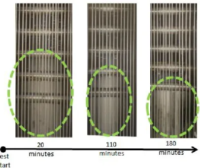
3.24 Pictures of the PCM undergoing melting after 20 minutes, 110 minutes and 180 minutes from the beginning of the test. . . 73
3.25 Energy and power profiles for a charging test. . . 74
3.26 Efficiency as a function of the temperature interval of the charge. . . 74
3.27 Efficiency as a function of the flow rate of the HTF during charge. . . 75
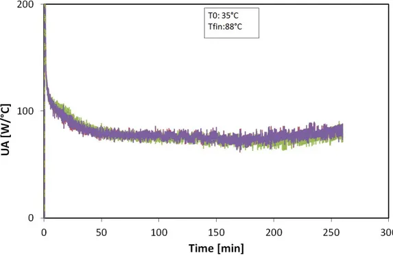
3.28 UA for three different charging tests at various flow rates. . . 76
3.29 Effect of inlet temperature on the charge of the storage. . . 77
3.30 Temperature profiles for a discharge test from 90°C to 70°C with HTF flow rate of 6 kg/min. . . 78
3.31 Energy and power profiles for a discharge test from 90°C to 70°C with HTF flow rate of 6 kg/min. . . 78
3.32 Effect of the initial temperature of the storage on the energy recovered and discharge power. . . 79
List of figures xi 3.33 Effect of flow rate on discharge power. . . 80 3.34 Effect of flow rate on recovered energy. . . 81 3.35 Dynamic test with 15 minutes charge and discharge, temperature profiles. . 82 3.36 Dynamic test with 30 minutes charge and discharge, temperature profiles. . 82 3.37 Results, in terms of energy, of dynamic tests with various charge/discharge
times. . . 83 3.38 A picture of the LTES based on the plate HEX. . . 86 3.39 Temperatures during a charge withm=15 kg/min, T. 0=65°C, Tfin=93°C. . . 87
3.40 Power supplied and cumulative energy during a charge withm=15 kg/min,. T0=65°C, Tfin=93°C. . . 88
3.41 Effect of HTF flow rate on the energy supplied during charging tests starting from 70°C. . . 89 3.42 Effect of HTF flow rate on the efficiency during charging tests starting from
70°C. . . 90 3.43 Energy and efficiency for various charging tests at different initial temperatures. 91 3.44 Time needed to reach target temperature as a function of the flow rate of HTF. 92 3.45 Time needed to transfer 20%, 50%, 70%, 80%, 90% and 95% of the total
charging energy. . . 93 3.46 Time needed to transfer 20%, 50%, 70%, 80%, 90% and 95% of the total
charging energy normalised over the total charging time. . . 93 3.47 Temperatures during a discharge withm=15 kg/min, T. 0=93°C, Tin=65°C . 95
3.48 Power recovered and cumulative energy during a discharge with m=15. kg/min, T0=93°C, Tin=65°C . . . 95
3.49 Effect of flow rate on the efficiency and the energy recovered from the storage in different testing conditions. . . 96 3.50 Effect of flow rate on discharge power under different conditions. . . 97 3.51 Effect of initial temperature on the discharge of the storage; (a) energy
recovered; (b) efficiency; (c) average discharge power. All the tests are carried out with mass flow rate of the heat transfer fluid of 20 kg/min. . . . 98 3.52 Optimization of power and efficiency during discharge. . . 99 3.53 Time needed to recover 20%, 50%, 70%, 80%, 90% and 95% of the total
discharging energy normalised over the total charging time. . . 101 3.54 Time needed to complete discharge in different tests with Tfin=70°C. . . 101
3.55 Temperature difference in the HTF circuit during two charges (a) and dis-charges (b) at different flow rates. The inlet temperature is the temperature indicated as T0. . . 102
3.56 U value for different charges. . . 102 3.57 Classification of the numerical methods proposed for the design of
PCM-based storage systems. . . 104 3.58 Rayleigh number for different ∆T. . . 108 3.59 Basic layout of the 1D model for the tube, in which the boundary conditions
are indicated in grey. . . 109 3.60 Basic layout of the 3D model for the fin and PCM, in which the boundary
conditions are indicated in grey. . . 110 3.61 Coupling of the 3D model for the fins and the 1D model for the tubes. Each
section of the tube in the 1D model is coupled to one part of the tubes in the 3D model (indicated by the dashed line). . . 111 3.62 Position of temperature probes in the model. . . 112 3.63 Comparison of simulated and measured temperatures for storage charging. . 113 3.64 Comparison of simulated and measured power for storage charging. . . 114 3.65 Comparison of simulated and measured temperatures for storage discharging. 115 3.66 Comparison of simulated and measured power for storage discharging. . . . 115 4.1 Methodology followed in the development of a thermochemical heat storage
system. . . 120 4.2 Main issues in the design of a thermochemical heat storage system. . . 121 4.3 Seasonal energy storage densities of the identified working pairs as a function
of the temperature lift. a:water as working fluid; b: other working fluids. Desorption temperature fixed at 100 °C, condensation temperature fixed at 30 °C, evaporation temperature at 10 °C. . . 124 4.4 Seasonal energy storage densities of the identified working pairs as a function
of the desorption temperature. a: water as working fluid; b: other working fluids. Condensation temperature fixed at 30 °C, adsorption temperature at 50 °C, evaporation temperature at 10 °C. . . 124 4.5 Thermodynamic cycle for the adsorption storage developed. . . 126 4.6 The adsorber filled with zeolite. . . 127 4.7 The adsorption storage realised. 1: adsorber, 2: phase changer, 3:
hy-draulics.4: vacuum valve. . . 128 4.8 P&ID of the complete prototype, including the hydraulic distribution. . . . 128 4.9 P&ID of the testing rig used for the characterization of the adsorption storage.130 4.10 Testing rig at CNR-ITAE lab. 1: heater, 2: hot storage, 3: MT/LT storage,
4:hydraulic connections, 5:plate heat exchanger, 6: management system, 7: Prototype under testing. . . 130
List of figures xiii 4.11 The experimental procedure followed for the characterization of the
adsorp-tion storage. . . 133 4.12 Temperatures during a typical test of the adsorption storage. . . 137 4.13 Power at the adsorber and phase changer during a typical test of the
adsorp-tion storage. . . 138 4.14 Energy at the adsorber and phase changer during a typical test of the
adsorp-tion storage. . . 139 4.15 Effect of desorption temperature on the energy stored for the three operating
modes examined. . . 141 4.16 Effect of evaporation temperature on the energy stored for the three operating
modes examined. . . 141 4.17 Effect of condensation temperature on the energy stored for the three
operat-ing modes examined. . . 142 4.18 Effect of desorption temperature on the discharge power for the three
operat-ing modes examined. . . 143 4.19 Effect of evaporation temperature on the discharge power for the three
operating modes examined. . . 143 4.20 effect of flow rate on the temperature difference in the inlet/outlet circuit of
the adsorber and phase changer. . . 144 4.21 Energy balance of the adsorber for a reference (90-35-5) cycle during
des-orption. . . 147 5.1 The Performance Indicators defined. . . 153 5.2 Boundaries used in the calculation of the Performance Indicators. The limit
List of tables
2.1 Materials for sensible heat storage and their properties. . . 9
2.2 Example of reactions usable for heat storage . . . 11
2.3 Comparison of thermal energy storage technologies . . . 14
2.4 Thermophysical properties of the various classes of PCMs . . . 23
2.5 Comparison of the various classes of PCMs . . . 23
2.6 Comparison of the various classes of PCMs according to their application. . 24
2.7 Thermophysical properties of the various adsorbents. . . 37
2.8 Comparison of adsorbent materials. . . 38
2.9 Comparison of adsorbent materials according to their application. . . 38
3.1 PCMs selected for the experimental characterization at ITAE. . . 49
3.2 Outcomes of the experimental characterization at ITAE. . . 52
3.3 Main features of PlusICE A82. . . 53
3.4 Main features of the realised prototype with fin-and-tube HEX. . . 63
3.5 The parameters investigated in the tests of the LTES with fin-and-tube layout. 69 3.6 Main features of the LTES based on the plate HEX. . . 85
3.7 The parameters investigated in the tests of the LTES with plate HEX. . . 86
3.8 Energy supplied, efficiency and average power during selected charging tests. 91 3.9 Coefficients used in the phase change equation for different numerical methods.103 4.1 Add caption . . . 127
4.2 The figures calculated for the evaluation of the adsorption storage. . . 135
4.3 Investigated conditions in the experimental testing of the adsorption storage. 136 4.4 Storage density and efficiency measured in different experimental conditions. 145 5.1 Construction indicators for the two systems based on latent heat technology. 153 5.2 Energy Indicators for the two developed LTES. . . 155
5.3 Testing conditions used in the calculation of Dynamics indicators for the two developed LTES. . . 157
5.4 Dynamics Indicators for the charge process of the two developed LTES. . . 157 5.5 Dynamics Indicators for the discharge process of the two developed LTES. . 158 5.6 Testing conditions used in the calculation of Energy and Dynamics indicators
for the adsorption TES. . . 159 5.7 Energy Indicators for the developed adsorption TES. . . 160 5.8 Dynamics Indicators for the adsorption TES. . . 161 5.9 Application of the suggested Indicators to the three storages developed. . . 162
Chapter 1
Introduction
1.1
Background
Energy production is the fulcrum of economical, scientific and social development worldwide. However, economic crisis, instability in the price of oil and gas, a difficult geo-political situation and a growing environmental conscience have favoured a massive introduction and development of renewable energy sources, clean, worldwide available and inexhaustible [1]. Moreover, energy efficiency has become an important target since energy savings and high-efficiency systems represent a fundamental part in the development towards a more sustainable and cleaner world [2]. Global energy policies reflect such a situation, both in the Western and Eastern countries. Indeed, production of energy from renewable sources represents a consistent share in the energy mix of most countries, including some emergent countries and, surprisingly, the majority of South American and African countries, as shown in Figure 1.1. Trend is towards an increase of installed capacity of systems employing renewable energy sources, as shown in Figure 1.2 for the solar thermal case.
Such a situation is also boosted by support policies promoted by governments for both privates and industries, in order to sustain the production, R&D and commercial diffusion of such systems. In fact, as to 2014, 144 countries have defined renewable energy targets and developed energy policies aimed at efficiency [3]. European Union has indicated the notorious 2020 targets as [4]:
- 20% reduction of greenhouse gaseous emissions; - 20% of renewables share;
Fig. 1.1 Share of renewables worldwide. SOurce:IEA
1.2 Benefits of using a thermal storage 3 Energy efficiency and reduction in CO2emissions, however are linked not only to
renew-able energies, but also to waste heat recovery. Considering as an example the transportation sector, a total of about 450 ktons of CO2per year emissions can be estimated, half of which
could be reduced by reducing the fuel needed for propulsion, mainly thanks to waste heat recovery [3, 5]. In such a context is hence clear that, in the next future, there would be an increasing and urgent need for architectures built for energy efficiency, in the residential, in-dustrial and mobility fields. Key component for a system created for efficiency enhancement is a thermal storage, to cover for the gap between heat generation and heat demand and to effectively distribute it through the various users.
1.2
Benefits of using a thermal storage
The utilization of thermal energy storage in various fields has long been established [6, 7] , not only in residential applications, but also in district heating [8] and in commercial and industrial ones [9, 7]. The main advantages deriving from the application of a thermal storage system can be summarised as follows:
- decoupling of the time between availability of a thermal source and its request; - better exploitation of energy, due to the possibility of producing and storing energy
when the cost is lower;
- reduction of peak demand, allowing energy providers to reduce the costs related to energy production and to increase the efficiency of generation;
- reduction of CO2emissions;
- possibility to size energy generation and distribution equipment for a lower power, with significant cost benefits.
1.3
Objective of the thesis
The present thesis deals with thermal storage technologies, with special focus on heat storage from solar radiation and waste heat recovery (e.g. from industrial processes and internal combustion engines). The main objective of the thesis are the development and experimental testing of thermal energy storage systems suitable for low-grade waste heat applications (T <100°C). The design of the systems will be described and the experimental measurements presented. Through the experimental benchmarking of the realised systems,
some considerations and optimization regarding the actual application of them under real boundaries will be discussed. Finally, a quantitative comparison between the technologies will be proposed, serving also a starting point for the definition of future standards.
1.4
Outline of the thesis
The thesis will be composed as follows:
- Chapter 2 will discuss the available technologies for thermal energy storage, starting from the theoretical basis and discussing the actual state-of-art with respect to material, component and prototype applications. In particular, thermal energy storage through the use of PCMs and sorption material will be investigated, by presenting the available materials with their advantages and disadvantages, the possible enhancement in their properties and the design issues related to the application in a full-scale system. - Chapter 3 will present the development of two thermal energy storage prototypes using
latent heat technology (with phase change materials) through experimental testing of lab-scale prototypes. numerical modelling and experimental measurements. Experi-mental results measured through a specifically designed testing rig will be analysed to discuss the behaviour of the components under the tested boundary conditions. Moreover, a numerical model, realised through the commercial software COMSOL Multiphysics and suitable for the simulation of latent heat storages, will be presented. Results from the experiments were used to validate the model.
- Chapter 4 will present the development of a thermal energy storage making use of adsorption technology. Thermodynamic and dynamic considerations used in the design phase will be presented. Experimental results measured in a dedicated testing rig will also be analysed and discussed.
- Chapter 5 will be dedicated to the discussion of the experimental methodology used for the assessment of the performance of the two systems. Some parameters will be identified for the description and comparison of thermal energy storage systems, ac-cording to the work currently ongoing within ECES Annex 30. Indeed, the parameters defined will be applied to the case studies presented in the previous Chapters and the open issues will be further discussed.
Chapter 2
Thermal energy storage: basics,
materials and technologies
2.1
Basics
Thermal Energy Storage (TES) is the whole assembly of technologies allowing for heat or cold energy to be used at a different time from generation. The basic flow diagram for a thermal energy storage process is shown in Figure 2.1: when excess hot or cold energy is available, this is used to charge the storage. When a demand for such energy exists, the storage is discharged. The storage period in between can vary from a few hours to months.
Fig. 2.1 Flow diagram of a thermal energy storage process.
A general classification of the methods for thermal energy storage which will be further analysed in the following sections, is given in Figure 2.2 [10].
A qualitative comparison between the various storage technologies, based on the dif-ferent energy density levels achievable with the above-mentioned technologies is shown in
Fig. 2.2 Classification of thermal storage methods.
Figure 2.3 [10]. It clearly shows that, starting from traditional sensible heat storage to the most efficient methods employing physical or chemical processes, the density enhancement can reach a ratio up to 8. The same concept is depicted in Figure 2.4, where volume needed to store 1850 kWh (with consideration of 25 % heat losses, based on a 70°C temperature increase for water) is shown [11].
Fig. 2.3 Energy density level for the different thermal storage technologies.
2.1.1
Storage with sensible heat
Sensible heat is the traditional methods used for storing energy. It is based on the increment in temperature of a storage medium when this is heated. The energy stored is linked to the temperature by a direct proportionality, as shown in Figure 2.5. The amount of energy stored
2.1 Basics 7
Fig. 2.4 Volume needed to store 1850 kWh, comparison among technologies. can be expressed through an equation of the type:
∆Q = mcp∆T (2.1)
With m the mass of the storage medium and cpits specific heat. Different heat storage
Fig. 2.5 Energy as a function of temperature,sensible heat.
materials can be applied for this type of storage, both in solid and liquid form, as summarised in Table 2.1 [12]. The temperature range covered by such materials is very high, from 0°C to 400°C. The advantage of liquid materials over solid ones is that active storage can be applied (without the need of an heat exchanger) and in general they require a simpler and cheaper storage design, because of the higher heat transfer efficiency. On the contrary, solid materials
do not have problems related to vapour pressure and the formation of possibly corrosive or explosives compounds and are in general very cheap. Since some of them are traditional construction materials, their implementation for the thermoregulation of buildings is easy. Their low thermal conductivity requires high contact area with the heat transfer fluid (HTF).
2.1.2
Storage with latent heat
Latent heat systems allow to accumulate energy by means of a phase change —mainly the solid-liquid one— as shown in Figure 2.6. Indeed, phase changes are associated to absorption or cession of energy at constant temperature. In this case, stored energy can be defined as:
∆Q = ∆H (2.2)
Where the ∆H is the enthalpy associated to the phase change. In case of the solid-liquid phase change:
∆H = λm (2.3)
With λm being the latent heat of fusion/solidification. If phase change is completed,
further energy is stored in the form of sensible heat and therefore, for a material starting in solid form at an initial temperature T0and heated to a final temperature Tfin, superior than
melting temperature, the total amount of heat storable is given by [13]: Qtotal= Qsensible,solid+ Qlatent+ Qsensible,liquid=
Z T m T0 mcpsdT+ λm+ Z Tf in Tm mcpldT (2.4)
Materials usually employed for TES with latent heat are called phase change materials or PCMs. The main advantages deriving from the utilization of latent heat, if compared to other technologies, are:
- higher energy density than sensible heat media;
- dependence of thermal behaviour from phase change temperature, a feature allowing to tailor the material according to the specific application to be realised. [13, 14].
2.1.3
Storage with chemical reactions
Chemical reactions can be used for heat storage/release, since between the reactants and the products of a chemical reaction there is a different enthalpy content, which is the so-called heat of reaction. When there is an exothermic reaction, heat will be released to the
2.1 Basics 9 Table 2.1 Materials for sensible heat storage and their properties.
Class Material Density Melting point Specific heat Heat of fusion Thermal conductiv-ity - - kg/m3 °C kJ/(kgK) kJ/kg W/(mK) Water Water 1000 0 4.184 333.55 0.58 Mineral oils Therminol VP-1 1068 12 1.546 - 0.137 Nitrate salts NaNO3 2261 306 1.655 172 0.514 Nitrate salts KNO3 2109 335 0.953 266 0.514 Hydroxide salts NaOH 2100 318 0.92 165 Hyroxide salts KOH 2040 380 1.34 150 0.5 Chloride salts ZnCl2 2907 280 75 0.5 Salt com-posites Solar salt NaNO3 -KNO3 (50-50) 1920 220 100.7 0.56 Solid materials Rocks 2560 0.960 0.48 Solid materials Concrete 2200 0.85 1.5 Solid materials Sand 1602 0.83 Solid materials Magnesia fire bricks 3000 1.15 5 Solid materials Cast steel 7800 0.6 40
Fig. 2.6 Energy as a function of temperature,latent heat.
environment, while an endothermic reaction will allow storing heat, as shown in Figure 2.7. Some conditions must be respected in order for a reaction to be useful for heat storage [10]: - heat of reaction should be relatively high, which does not usually happens when all of
the components in the reaction are liquid or solid; - the products of the reaction must be storable; - the reaction must be reversible.
As for latent heat storage, the heat stored with chemical reactions, can be expressed in the form:
∆Q = ∆Hr (2.5)
Where ∆Hr is the heat of reaction associated to the particular chemical system.
Drawbacks in the use of chemical reaction for energy storage are linked to the fact that they involve chemical bonding, which are strong, and accordingly require a huge amount of energy to be modified. Direct consequence is that chemical reaction are generally useful only for high temperature energy storage. Some examples of chemical reactions and their correspondent temperature levels are given in Table 2.2.
It is possible to notice that several chemical reactions exist, with the potential to store heat at a temperature level variable from 100°C to 1500°C and high energy density. However, as previously stated, the difficulties in handling the products of the reaction and the control of the reaction itself have limited the practical application of such systems up to now.
2.1 Basics 11
Table 2.2 Example of reactions usable for heat storage
Class of material Reaction Tr ∆Hr ∆Hr
- - °C kJ/mol kWh/m3
Hydroxides Mg(OH)2⇔ MgO + H2O 268 78 442
Hydroxides Ca(OH)2⇔ CaO + H2O 521 100 410
Ammonium salt NH4HSO4⇔ NH3+ H2+ SO3 467 337 727
Salt hydrates MgSO4· 7H2O⇔ MgSO4+ 7H2O 122 411 389
Salt hydrates CaCl2· 2H2O⇔ CaCl2· H2O+ H2O 174 48 84 Salt hydrates CuSO4· 5H2O⇔ CuSO4· H2O+ 4H2O 104 226 287
Salt hydrates CuSO· 4H2O⇔ CuSO + 4H2O 205 73 163
Peroxide salts BaO2⇔ BaO +12O2 782 75 305 Peroxide salts KO2⇔12K2O+34O2 668 101 423 Carbonates CaCO3⇔ CaO +CO2 896 167 626
Carbonates BaCO3⇔ BaO +CO2 1497 212 661
Metal hydrides MgH2⇔ Mg + H2 293 79 605 Metal hydrides Mg2NiH4⇔ Mg2Ni+ 2H2 253 128
-Catalytic reactions NH3⇔ f rac12N2+32H2O 195 49 546
Catalytic reactions SO3⇔ SO2+12O2 767 98 678
Reforming CH4+ H2O⇔ CO + 3H2 687 205
-Fig. 2.7 Heat storage process with chemical reaction
2.1.4
Storage with heat of adsorption
Adsorption is the phenomenon involving bonding of a vapour or gaseous substance on the surface of a solid material, as schematically shown in Figure 2.8. During adsorption the gas molecules are concentrated on the surface of the solid, while during the reverse process, called desorption, molecules leave it.
Fig. 2.8 Heat storage process through adsorption.
The material capable of adsorbing other components is called adsorbent, while the material being adsorbed is called adsorbate [15]. A general distinction is made between:
- physical adsorption, or physisorption, involving Van Der Waals forces and hydrogen bonding;
2.1 Basics 13 As shown in the picture, desorption process requires heat, which is released when adsorption occurs. Such amount of heat, called heat of adsorption, could be stored if a proper system architecture is built. Therefore, for a thermochemical system employing adsorption process, stored heat can be expressed as:
∆Q = ∆Hads (2.6) Where ∆Hads is the adsorption heat linked to the process.
Chemisorption, involving stronger forces, is associated with a higher heat of adsorption than physical bonding, but the latter is almost unanimously preferred, since it does not require elevated activation energies for the reaction to occur [15].
2.1.5
Comparison of thermal energy storage technologies
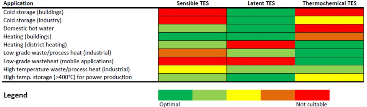
Table 2.3 presents a comparison between the available thermal energy storage technologies, focusing especially on the technical aspects and their level of readiness. In general, it is possible to assert that sensible storage is commercially available, also in bigger sizes and presents the easiest construction. On the other hand, its applicability is limited to short term storage and the energy density achievable is low. Latent heat storage presents a higher energy density. The application of PCMs is often limited by their degradation over cycling and the low thermal conductivity. Thermochemical storages present the highest energy density and have a storage period that is theoretically unlimited, without the need for bulky insulation and, when referring to sorption storage, with limited corrosion issues. On the contrary, the system layout is complex and requires several components, which have caused its application to be restricted mostly to laboratory scale up to now. Instead, in Figure 2.9, the most suitable technology for each of the common applications requiring a thermal storage is shown. Such an indication is based on either intrinsic limitations of the technology (e.g. the use of latent heat storage for district heating and cooling networks is limited by the relevant effect of heat losses ) or design consideration: the use of thermochemical storage for building applications is not advisable due to the bulky dimensions of such systems, which make them more suitable for industrial applications. In the case of mobile applications, where high energy density and no limitations on heat storage period are key constraints, only thermochemical systems were listed as suitable. Instead, in the case of cold storage, systems with high efficiency and compact enough for real applications belong to the category of latent TESS, since sensible heat storage presents time limitations and thermochemical systems have an intrinsic efficiency that is quite low (their theoretical COP never exceeds 0.67).
Table 2.3 Comparison of thermal energy storage technologies
Sensible TES Latent TES Thermochemical TES Temperature range (°C) 0÷1200 -100÷1000 150÷1500 Storage density (kWh/t) 10÷50 50÷100 150÷250 Storage density (kWh/m3) 50 100 500 Power (kW) 1÷10000 1÷100 10÷1000 Efficiency(%) 50÷90 50÷90 50÷100 Storage period hours to days hours to days hours to months
Lifetime long limited due to degradation of materials over cycling theoretically unlimited TRL 9 4÷7 4÷6 Environmental impact
negligible negligible negligible Safety issues no depends on
materials used, but usually limited
limited for sorption TES, higher concern
for chemical TES Corrosion issues mild medium to high low for sorption
TES, high for chemical TES Impact of
insulation
high high low
Technical complexity of the
system
low medium high Flexibility
(regulation, partial charge/discharge
etc)
2.2 Latent heat thermal energy storage: materials and technology 15
Fig. 2.9 Comparison of heat storage technologies on the basis of their application.
2.2
Latent heat thermal energy storage: materials and
tech-nology
As previously stated, the definition of PCM materials includes all the materials undergoing a phase change and adoptable for thermal energy storage. However, since solid-liquid phase change is definitely the most common studied and employed in practical systems, only the classes of PCMs used for this phase change will be considered in the following description. A lot of effort has been recently put in the search for optimal PCMs for the most different applications, ranging from solar energy storage to ice storage, from thermoregulation of buildings to food storage systems [16]. The properties required for an ideal PCM are several, and often contrasting one another: it is consequently impossible for a material to possess all of them, even when manipulation with external compounds is realised. Indeed, the following features are required: [14, 17, 13]:
THERMAL PROPERTIES
- Phase change temperature compatible with the characteristic temperature level of the desired application;
- High latent heat per volume unit, as to allow storing high amount of heat in a compact volume;
- High specific heat, in order to store a significant amount of energy also during heating phase;
- High thermal conductivity both in solid and liquid status to minimise the temperature difference needed for phase change.
PHYSICAL PROPERTIES
- Low volume expansion due to the temperature variation, in order to reduce the volume needed to compensate for thermal expansion;
- Low vapour pressure, to facilitate the eventual encapsulation; - High density, to reduce storage volume.
CHEMICAL PROPERTIES
- Long-term stability, to avoid or reduce material degradation due to cycling during operation;
- Compatibility with materials of the storage, to reduce problems related to corrosion or chemical reaction with the containers;
- No toxicity, no flammability and no explosion hazard, to guarantee for a reliable and safe employment in all the environments, especially in residential application.
KINETIC PROPERTIES
- Absence of or limited subcooling, to avoid thermal heat transfer to happen at tempera-tures different from design conditions;
- High nucleation and growth rate, to ensure phase change is completed in short times. ECONOMIC PROPERTIES
- Abundance; - Easy provisioning; - Low cost.
2.2.1
Classification of Phase Change Materials
The most general classification of PCMs is the one based on the phase transition for which they are used, i.e. solid-solid, solid-liquid and liquid vapour. Even though transitions from solid or liquid to vapour state are the ones associated with the highest enthalpies [16], for practical reasons solid-liquid transitions are the ones widely employed in the various applications. There is no unique classification of PCMs belonging to this class and several models can be found in literature, but one of the most complete, which will be taken as
2.2 Latent heat thermal energy storage: materials and technology 17
reference, is the one reported in [18] and schematically represented in Figure 2.10. In the following sections, general information about each class of materials, with special focus on the recent advancement of the research will be given, while at the end a comparison between the various classes of materials will be presented.
2.2.2
Organic PCM
Organic PCMs are in general stable both physically and chemically, thus avoiding the need for stabilisers or additives. One common feature of organic PCMs is the congruent phase change, meaning no segregation or latent heat decrement arises after multiple melting/solidification cycles, which occurs also with high nucleation rates. Other peculiarities are the low corrosion rates with metal and recycling possibilities. However, disadvantages in the application of this class of PCMs include the low thermal conductivity, the high volume expansion during phase transition, low density, flammability and the elevated cost [16, 14].
Paraffins
Among organic PCMs, an important class for solar and low-grade waste heat storage is those of paraffins, a mixture of mostly straight chain n-alkanes CnH2n+2, with n ranging between
20 and 40. Among the advantages determining a wide research associated with paraffins, there are their non-toxicity, low segregation, high stability, no corrosion problems on metals and a low cost. As stated in the previous section, like most organic PCMs, paraffins are characterised by low density, low conductivity and flammability. Melting temperature (the operating temperature for a PCM), density and latent heat can be increased by increasing chain lengths or creating mixtures of different hydrocarbons [18].
Fatty acids
Fatty acids are organic compound with chemical formula CH3(CH2)2nCOOH, derived from
animal or vegetable sources, which makes them biodegradable and non-toxic. Compared to paraffins, they present high latent heat and good stability to cycles, with no subcooling effect, but they present a higher cost (twice or three times that of paraffins) and can determine metal corrosion [19]. Flammability is more marked than in paraffins, and therefore exposition to high temperature, flames or oxidising agents should be avoided [12]. Melting temperature range of fatty acids is generally below 70°C and are then employed mainly for buildings or low-grade heat storage [20, 21, 17].
2.2 Latent heat thermal energy storage: materials and technology 19 Polyalcohols
Sugar alcohols (also known as polyalcohols) have been proposed as storage materials at medium temperatures (90–200 °C) for a long time, for their high melting enthalpies, low cost and non-toxicity [14]. On the other hand, different tests made on polyalcohols have reported a high grade of subcooling, which can severely compromise their effective application and which should be addressed in the hypothesis of a massive development. One feature of polyalcohols is the numerous crystalline forms that can be observed, each one with specific characteristics, as a function of additives and the preparation technique employed [22–24]. Esters
Esters are derived from acids in which one hydroxyl (–OH) group is replaced by one alkyl (–O) group [14]. Among the features of fatty acid esters are the narrow melting range and the limited degree of subcoolings. Their melting point is usually lower than 60°C. They are widely available and show excellent stability [22].
Polymeric materials
Importance of polymers among PCMs is continuously growing, thanks to the easiness with which modifications to their structure can be achieved in order to tailor properties for a specific application [14]. Among polymers, two of the most common used are HDPE and polyethilenglycole [16, 14, 24].
Bio-based PCM
Bio-based PCMs are a class of materials obtained from industrial residues, as soy oil, coconut oil, palm tree oil and animal fat and having melting point between 23°C and 78°C. With respect to other classes of PCMs they possess high latent heat, higher chemical stability, low flammability and no oxidation even after several cycles [25, 26]. Like other organic materials, though, their thermal conductivity is low, but some materials with increased thermal conductivity have been prepared by adding particles of graphite, carbon or metals.
2.2.3
Inorganic PCMs
The class of inorganic phase change materials mainly includes three categories of PCMs: salts and salt hydrates, metals and eutectic mixtures. In general, inorganic materials, if com-pared to organic ones, have a higher enthalpy (almost double), but a tendency to degradation after cycles, thus reducing their performances, considering also the presence of undesirable
phenomena such as segregation and subcooling . Thermal conductivity is higher and flamma-bility low, but corrosion can arise as a consequence of their contact with metal surfaces [18, 27].
Hydrated salts
Hydrated salts are those salts that, during crystallisation, absorb one or more water molecules, the ratio depending on the specific material. Water included in such structures is generally called crystallisation or hydration water. Generic chemical formula for a hydrated salt is AxBy·n(H2O) where n represents number of water molecules and AxBy represents metal
carbonate, sulfite, phosphate, nitrite, acetate, or chloride. For this class of materials, there is no actual liquid-solid transition, their change is rather linked to hydration or dehydration of the salt, according to the following reactions:
AxBy· n(H2O) ⇔ AxBy· m(H2O+ (n − m)(H2O) AxBy· n(H2O) ⇔ AxBy+ (n(H2O)
Hydrated salts are particularly interesting for their application as PCMs for their latent heat, high thermal conductivity, low thermal expansion, low corrosion rate on metals and compatibility also with plastics, low toxicity and affordable cost [16, 27]. The behaviour of the salts during phase transition is quite complex and is influenced by a wide variety of factors, such as the presence of additives or the velocity with which temperature variation occurs. According to these, melting can be:
- congruent, if dehydrated salt is completely soluble in crystallisation water at phase change temperature;
- incongruent, if the salt is not completely soluble in crystallisation water at phase change temperature;
- semi-congruent, if solid and liquid have different composition because of conversion of the hydrate into a lower-hydrated material through the loss of water [18].
Incongruent behaviour is the main limitation to their usage: since n moles of water of hydration are not sufficient to dissolve one mole of salt, the resulting solution is supersaturated and the solid salt, due to its higher density, settles down at the bottom of the container and is unavailable for recombination with water. This results in a constant decrement of latent heat available [18]. Numerous techniques have been studied to try to solve the complications linked to the incongruent melting, such as the addition of external water at regular times to reduce precipitation of solid: this is known as the “extra water principle”, which gives good results in terms of material stability but, at the same time, increases the temperature range
2.2 Latent heat thermal energy storage: materials and technology 21 for melting and, more importantly, reduces latent heat of melting and requires complicated storage tanks. Another proposed solution is the addition of thickening agents to hold the solid in suspension (at the expense of kinetic of heat transfer) or encapsulation to reduce separation [22].
Metals
Metals and metal alloys could be considered optimum PCMs, especially for high temperature applications, because of their high latent heat per volume unit, high thermal conductivity, low vapour pressure, good stability and repeatability of the phase change, However, not much literature exists on their application [28].
Eutectics
An eutectic is a minimum-weight composition of two or more components which melt and freeze congruently, in order to form a mixture of the component crystals. The main advantage of eutectic compounds is that segregation is not likely to occur, considering also that melting happens at a specified temperature instead of a range. Eutectics used in thermal energy storage applications are mainly binary and ternary mixtures of inorganic salts: nitrate, chloride and sulphate salts of alkali and alkaline metals, such as magnesium, potassium, lithium and calcium are used as the main compounds to produce medium temperature eutectic mixtures [20], mainly for applications in concentrated solar plants.
2.2.4
Comparison of PCMs
In Table 2.4 the main thermophysical properties of the various classes of PCMs are reported, while in Table 2.5 a more comprehensive comparison between the materials is presented, highlighting the advantages and issues related to the application of each class of materials. All data have been taken from [28, 16, 18, 14, 25, 29, 27, 12, 30, 31, 22, 32]. Organic PCMs present low to medium melting points (-10 to 90 °C) and are widely available at a low cost (even though fatty acids are comparatively much more expensive than paraffins and esters). They have excellent thermal and chemical stability and a good latent heat per unit of weight, even though their density is generally lower than other class of materials, which penalises the latent heat on volume basis. Moreover, the exhibit little or no subcooling. On the other hand, they have extremely low thermal conductivity, high volume expansion and are flammable. Inorganic PCMs are characterised by higher latent heat per unit of weight and volume and the thermal conductivities are higher than organic materials, especially in the case of metal. Salt hydrates and eutectics are also widely available at cheap or reasonable prices and are not
flammable. On the other hand, they require nucleating and thickening agents to minimize the subcooling and they are highly reactive to metal materials. Their melting points (80 to 700°C) make them promising candidates for medium to high temperature applications. Finally, in Table 2.6, the applications that have been investigated, both in literature and at a commercial stage, are schematically represented: organic PCMs are the most extensively used, both in buildings and for coupling with solar systems of various types (production of domestic hot water, concentrated and non-concentrated solar for heat production), as well as in the textile industry, mainly for military textiles. Sugar alcohols, despite their poor thermal stability, have been considered for solar and waste heat storage, the same applications that fit the class of polymers. Hydrated salts have been extensively studied as well, especially since they are cheap, mainly for medium temperature applications. Up to now, the sector where PCMs have been extensively studied and applied is the thermoregulation of buildings, either with passive or active methods (i.e. inclusion of PCMs in gypsum and wallboards or coupling with heat pumps and air conditioning systems), but other fields of application are growing, such as the transportation industry, for the thermal buffer of vehicles, and the cooling of electronic devices. Further R&D is instead needed for medium to high temperature storage, both in industry and solar-related cases.
2.2 Latent heat thermal energy storage: materials and technology 23 T able 2.4 Thermoph ysical properties of the v arious classes of PCMs T able 2.5 Comparison of the v arious classes of PCMs
T able 2.6 Comparison of the v arious classes of PCMs according to their application.
2.2 Latent heat thermal energy storage: materials and technology 25
2.2.5
Design issues: heat transfer enhancement of PCMs
One of the main drawbacks limiting the actual performance of latent heat storage systems is the low thermal conductivity of most PCMs, which negatively affects the heat transfer in the final system and reduces the practical applicability of such a technology. Figure 2.11 presents an overview of the methods proposed and studied for increasing the heat transfer when dealing with PCMs embedded in a storage system [27, 33, 30]. Great research efforts have been dedicated to the development of the material and the enhancement of its intrinsic characteristics. One of them is the addition of highly conductive porous materials to the base PCM. Such a choice brings a double benefit: the overall thermal conductivity of the material is increased, and extended heat exchange area is available, thus further increasing heat transfer. In [33], various experimental and numerical studies are reported. Porous materials used as matrix include metal foams (aluminium and copper) and graphite (either expanded or as a foam) , while in the majority of cases paraffin is used as the base PCM. It has been found that aluminium foam and expanded graphite are the most widely used thermal conductivity enhancers and allow reaching thermal conductivities up to 8 times higher than the one of the base material. It is, however, worth noticing that the low mass/volume fraction of the porous media decreases the volumetric heat storage density of the system. The use of highly conductive materials dispersed in the base PCM has also been investigated recently. Among such filler, there are nanopowders (such as Al, CuO, Cu, SiC), nanowires (NW) and carbon fillers (nanotubes). Outcome of the various studies has been that such material can increase the thermal conductivity of the PCM up to an order of magnitude. Among the low density materials that can, instead, be dispersed, carbon fibres, especially in combination with paraffins, have been studied. Such a method, even if not as effective as the previous ones, can overcome the problem of reducing the volumetric heat storage density of the system due to the high fraction of void of the matrix.
When considering the design of the storage system, heat transfer enhancement can also be achieved by using external devices, such as fins and heat pipes. Fins are metal surfaces that allow increasing the heat transfer area in contact with the PCM and can be realised in various shapes. Anular, elicoidal, longitudinal and transversal fins have been studied, mainly on shell and tube heat exchangers [33], and in all cases (i.e. disregarding the geometry and materials of the fins) the addition of fins has proved to increase the storage power, as well as the efficiency of the system during both charge and discharge. Common materials used for finned configurations include aluminium, copper and graphite. One important aspect to take into account is that fins do not affect the flow of the HTF, thus they do not increase the pressure drop of the storage. Another outcome of all the studies reported in literature is that
CFD simulation is often needed to proper design an optimized layout, in terms of geometry and number of the fins employed.
Another technique suitable to increase the thermal performance of a latent thermal energy storage (LTES) is the use of heat pipes, that make use of the condensation/evaporation of a fluid for the transfer of heat to the PCM. The advantage in the use of heat pipes is that they are able to transfer a high amount of heat in a narrow temperature difference, which is the case of application of the vast majority of latent heat storages. Up to now, however, the technical implementation of such devices is still under exploitation and further work is necessary.
Finally, a method proposed for heat transfer enhancement is the combination of PCMs with different melting temperatures, so that the heat flow inside the system is kept constant [33], especially when shell-and-tube configurations are used. However, most of the existing studies are numerical, while the practical and engineering aspects need to be developed. One of the most promising field of research is the application of "combined heat transfer enhancement": increasing the heat transfer area and enhancing the thermal conductivity of PCM simultaneously, which could lead to a massive application of latent heat storage technology in future years and a commercialization of more systems based on this technology.
2.3
Adsorption heat thermal energy storage: materials and
technology
Differently from latent heat storage, storage involving the adsorption process requires a basic understanding of the working principles behind the phenomena on which it is based, that will be briefly described in the following section, while a general overview on materials for adsorption storage will be presented consecutively.
2.3.1
Operating principle of adsorption TES
Adsorption TES is based on the chemical potential deriving from the breaking of bonds between the sorbent material and the working fluid. It is mainly distinguished in:
- open adsorption storages; in which the system is not isolated from external environment and heat exchanges are made between air streams and the adsorbent bed;
- closed adsorption storages, in which the system is “air-free” and isolated from the environment, as in adsorption heat pumps.
2.3 Adsorption heat thermal energy storage: materials and technology 27
The working principle of open and closed adsorption storage is represented in Figure 2.12 and Figure 2.13, respectively.
Fig. 2.12 Working principle of heat storage with open adsorption systems.
Fig. 2.13 Working principle of heat storage with closed adsorption systems.
In an open system, heated dry air, exiting for example from a solar panel, passes through a heat exchanger containing the adsorbent, generally in pellet or grains, thus releasing water contained in it, and exits the bed cool and saturated [34]. During discharge, humid air enters the adsorbent, which adsorbs its water content, leaving the air stream warmer and drier. It has to be noted that, for the discharging process to occur at acceptable rates, humidity content of
2.3 Adsorption heat thermal energy storage: materials and technology 29 entering air through the adsorbent bed must be high [35]: when this condition is not fulfilled a humidifier is used to wet the air [34]. From the system design point of view, advantages in open systems are linked to their low investment cost and easiness in realisation, since only one component is needed.
In closed systems, the storage tank is composed of two vessels, connected by a duct for vapour to pass among the chambers. During charging, hot water is supplied to the reactor, which is a vessel containing a heat exchanger filled with the adsorbent, as to realise the desorption process. Adsorbate vapour flows through the connection into the other vessel, which is a condenser/evaporator. During charging, vapour passes into liquid form and condensation heat is released to a heat sink. Discharging process makes use of an external heat source to drive the evaporation process in the second vessel, working in this case as evaporator and then the adsorbate vapour flows through the other vessel, where adsorption occurs. Depending on the practical requirement, a cooling effect can be produced by the evaporator or a heating effect can be created by the reactor [35]. This feature makes the sorption thermal storage processes able to offer “cold storage” function in summer and “heat storage” function in winter. If external temperature is too low to drive evaporation process during discharging, another source, such as ground boreholes, is needed. Compared to open systems, closed ones involve a more complex configuration, leading to higher investment costs, together with maintenance necessities since the whole system works under vacuum conditions that should be periodically checked. However, flexible operation and a wider choice of working pairs make them promising and interesting for application in TES.
2.3.2
Basic cycle of closed adsorption TES
Figure 2.14 reports the working cycle for a closed adsorption TES on the Clapeyron diagram, where the main heat fluxes associated with each phase are represented. Indeed, the following sections will be mostly devoted to closed adsorption systems, but Figure 2.15 and Figure 2.16 schematically represent the typical adsorption TES architecture both for open and closed systems, where the heat contributions to each phase of the storage process are highlighted. In a closed adsorption TES, during charge (i.e. desorption), the the adsorbent material, which is at the maximum content of adsorbate, is regenerated by supplying the amount of heat:
Qch= Qish+ Qdes (2.7) Qish, is the isosteric heat, which represents the amount of sensible thermal energy spent to heat up the adsorbent material and the adsorbate under isosteric conditions, in order to increase the pressure of the adsorber up to the condenser pressure pcond. Qdes instead is
the energy spent to desorb the adsorbate, plus a small amount of specific heat to increase the adsorbent material temperature up to the final temperature, Tdes. During this phase, the
desorbed vapour is condensed in the condenser, where the heat of condensation, Qcond, is
released. Once the charging process is completed, the connection between condenser and adsorber is closed. If the adsorbent and adsorbate are kept separated, the energy can be stored for a theoretically infinite period. During discharging phase (i.e. adsorption), the adsorbent material is enriched in adsorbate content, releasing the amount of heat:
Qdisch= Qisc+ Qads (2.8)
Qisc, is the isosteric heat delivered during the cooling process, during which the pressure
of the adsorber is lowered to the evaporator pressure pev. Qads instead is the enthalpy of
adsorption, plus a small amount of specific heat associated to the cooling of the adsorbent to the final adsorption temperature, TadsDuring this phase, the adsorbate is evaporated in the
evaporator adsorbing heat from the ambient, Qev [36].
According to the operation of the storage, a different useful effect can be obtained: - if short term heat storage is needed, the useful energy extracted from the storage is the
energy of condensation and the energy of adsorption;
- if long term heat storage is required, the useful energy extracted from the storage is the energy of adsorption;
- if the storage is needed to provide cold energy, energy of evaporation represents the useful effect of the process.
2.3.3
Thermodynamics of closed adsorption TES
The heat provided during the charging process is defined as [34]: Qch = Z Tads Tdes Z wmax wmin mcpadsorbent(T )dw + Z wmax wmin ∆Hadsdw (2.9)
The specific heat of the adsorbent material is calculated according to the rule of linear addition [36]:
cp(w) = (1 − w)cpdry+ wcpre f (2.10) where: cpdry is the specific heat of the dry adsorbent material, waveis the average amount
2.3 Adsorption heat thermal energy storage: materials and technology 31
Fig. 2.14 Clapeyron diagram for a closed adsorption TES.
Fig. 2.16 Heat fluxes in a closed adsorption TES. during the discharging process is similarly defined as:
Qdisch= Z Tads Tdes Z wmax wmin mcpadsorbentdw+ Z wmax wmin ∆Hadsdw (2.11)
The heat released at the condenser is given by:
Qcond = λcondre f(Tcond)(wmax− wmin) (2.12)
where λcondre f is the heat of condensation of the refrigerant, calculated at the condensation
temperature. The heat at the evaporator is given by:
Qev= λevre f(Tev)(wmax− wmin) (2.13)
where λevre f is the heat of evaporation of the refrigerant, calculated at the evaporation
temperature.
Usually, when speaking of adsorption TES, the energy density of the material is calculated considering the adsorption enthalpy [35]:
Emads,T ES = ∆Hads∆w madsorbent (2.14) or EVads,T ES = ∆Hads∆w Vadsorbent (2.15)
2.3 Adsorption heat thermal energy storage: materials and technology 33
2.3.4
Adsorbent materials
The main features for an adsorbent to be suitable for thermal storage are [34, 35, 37]: - high energy storage density, which means high heat of adsorption;
- low charging temperature;
- high differential uptake of adsorbate;
- high heat and mass transfer properties to ensure designed output power; - thermal stability;
- low cost.
Indeed, as for PCMs, no material among the currently synthesized ones possesses all these features, and therefore a choice must be made based on specific application. A general outline of materials available for solid sorption systems is given in Figure 2.17.
Fig. 2.17 Classification of adsorbent materials. Silica gels
Silica gels are the most common among sorbents used in heat pumps applications, for their low cost and reliability and for the desorption temperatures lower than 90°C. However, their calculated storage density is lower than water (50 kWh/m3against 70 kWh/m3of water for
at ∆T of 60°C) and therefore they might possess some attraction only for seasonal energy storage [35].
Zeolites
Zeolites are crystalline aluminosilicates of alkali or alkali earth elements, such as sodium, potassium, and calcium [38], with a tetrahedral structure, with each tetrahedron centred on an Al or Si atom and the oxygen atoms on the vertexes. Both natural and synthesised zeolites are available, the most common being types 4A, 5A, 10X, 13X and Y Several studies have been conducted on the use of natural zeolites for thermal storage [35], for their low cost and wide accessibility. The main drawbacks linked to the use of such materials is the high heat temperature needed to drive the desorption, which occurs at 150-200°C. Among the studies on zeolites, Shigeishi et al. [39] compared activated alumina and silica gel with synthetic zeolite 4A, 5A, and 13X and determined zeolite 13X was the best adsorbent, with an energy density of 148 Wh/kg. Janchen et al. [38] studied in a lab-scale storage prototype different modified zeolites of the type NaX, NaY and NaA as well as mesoporous materials impregnated with hygroscopic salts. Their results showed that for Mg and Li-exchanged zeolite an energy density of 149 Wh/kg to 225 Wh/kg can be obtained.
Novel Porous Materials
Nowadays, (silico)aluminophosphates (SAPOs,AlPOs) and metallic organic framework (MOFs) can be considered the most promising classes of sorbents in terms of high water adsorption capacity and low regeneration temperature [40]. A number of studies were carried out on different types of (silico)aluminophosphates (ALPO5, ALPO18, SAPO34, etc.) [41, 42], confirming the interesting properties of such materials for adsorption cycles. Regarding their application for thermal energy storage, Janchen et al. [38] have measured the density energy of SAPO-34 and obtained a value of 290 Wh/kg.
In addition, evaluation of super-molecular Metal-Organic Frameworks (MOFs) for appli-cation in sorption systems is a major trend of the research in this field. These materials are made of metal ions or clusters connected to organic molecules. MOFs attracted attention due to the open crystalline structure and very high surface area. Some studies revealed a large capacity of water adsorption under realistic operating conditions [41, 42]. Possible obstacles for practical use are a significant ad/desorption hysteresis and insufficient stability.