ScienceDirect
Available online at Available online at www.sciencedirect.comwww.sciencedirect.com
ScienceDirect
Energy Procedia 00 (2017) 000–000www.elsevier.com/locate/procedia
1876-6102 © 2017 The Authors. Published by Elsevier Ltd.
Peer-review under responsibility of the Scientific Committee of The 15th International Symposium on District Heating and Cooling.
The 15th International Symposium on District Heating and Cooling
Assessing the feasibility of using the heat demand-outdoor
temperature function for a long-term district heat demand forecast
I. Andrić
a,b,c*, A. Pina
a, P. Ferrão
a, J. Fournier
b., B. Lacarrière
c, O. Le Corre
c aIN+ Center for Innovation, Technology and Policy Research - Instituto Superior Técnico, Av. Rovisco Pais 1, 1049-001 Lisbon, PortugalbVeolia Recherche & Innovation, 291 Avenue Dreyfous Daniel, 78520 Limay, France
cDépartement Systèmes Énergétiques et Environnement - IMT Atlantique, 4 rue Alfred Kastler, 44300 Nantes, France
Abstract
District heating networks are commonly addressed in the literature as one of the most effective solutions for decreasing the greenhouse gas emissions from the building sector. These systems require high investments which are returned through the heat sales. Due to the changed climate conditions and building renovation policies, heat demand in the future could decrease, prolonging the investment return period.
The main scope of this paper is to assess the feasibility of using the heat demand – outdoor temperature function for heat demand forecast. The district of Alvalade, located in Lisbon (Portugal), was used as a case study. The district is consisted of 665 buildings that vary in both construction period and typology. Three weather scenarios (low, medium, high) and three district renovation scenarios were developed (shallow, intermediate, deep). To estimate the error, obtained heat demand values were compared with results from a dynamic heat demand model, previously developed and validated by the authors.
The results showed that when only weather change is considered, the margin of error could be acceptable for some applications (the error in annual demand was lower than 20% for all weather scenarios considered). However, after introducing renovation scenarios, the error value increased up to 59.5% (depending on the weather and renovation scenarios combination considered). The value of slope coefficient increased on average within the range of 3.8% up to 8% per decade, that corresponds to the decrease in the number of heating hours of 22-139h during the heating season (depending on the combination of weather and renovation scenarios considered). On the other hand, function intercept increased for 7.8-12.7% per decade (depending on the coupled scenarios). The values suggested could be used to modify the function parameters for the scenarios considered, and improve the accuracy of heat demand estimations.
© 2017 The Authors. Published by Elsevier Ltd.
Peer-review under responsibility of the Scientific Committee of The 15th International Symposium on District Heating and Cooling.
Keywords: Heat demand; Forecast; Climate change
Energy Procedia 158 (2019) 2834–2840
1876-6102 © 2019 The Authors. Published by Elsevier Ltd.
This is an open access article under the CC BY-NC-ND license (http://creativecommons.org/licenses/by-nc-nd/4.0/)
Peer-review under responsibility of the scientific committee of ICAE2018 – The 10th International Conference on Applied Energy. 10.1016/j.egypro.2019.02.046
10.1016/j.egypro.2019.02.046
© 2019 The Authors. Published by Elsevier Ltd.
This is an open access article under the CC BY-NC-ND license (http://creativecommons.org/licenses/by-nc-nd/4.0/)
Peer-review under responsibility of the scientific committee of ICAE2018 – The 10th International Conference on Applied Energy.
1876-6102
Available online at www.sciencedirect.com
ScienceDirect
Energy Procedia 00 (2018) 000–000www.elsevier.com/locate/procedia
1876-6102 Copyright © 2018 Elsevier Ltd. All rights reserved.
Selection and peer-review under responsibility of the scientific committee of the 10th International Conference on Applied Energy (ICAE2018).
10
thInternational Conference on Applied Energy (ICAE2018), 22-25 August 2018, Hong Kong,
China
Optimal design of a hybrid energy plant by accounting for the
cumulative energy demand
Hilal Bahlawan
a*, Mirko Morini
b, Michele Pinelli
a,
Witold-Roger Poganietz
c, Pier Ruggero Spina
a, Mauro Venturini
a aDipartimento di Ingegneria, Università degli Studi di Ferrara, Via Saragat 1, 44122 Ferrara, ItalybDipartimento di Ingegneria e Architettura, Università degli Studi di Parma, Parco Area delle Scienze 181/a, 43124 Parma, Italy cKarlsruhe Institute of Technology (KIT), Karlsruhe, Germany
Abstract
In this paper, the optimal design of a hybrid energy plant composed of a solar thermal collector, a photovoltaic panel, a combined heat and power system, an absorption chiller, an air source heat pump, a ground source heat pump and a thermal energy storage is studied. The size of each technology is optimized by applying a model implemented in Matlab® environment. The optimization
goal is the minimization of the primary energy consumed throughout the life cycle of the hybrid energy plant by using a genetic algorithm. The primary energy consumed during the manufacturing phase of the hybrid energy plant is represented by the cumulative energy demand and is calculated by carrying out a cradle to gate life cycle assessment. The primary energy consumed during the operation phase is evaluated by simulating the system throughout one year. The cumulative energy demand of each system composing the hybrid energy plant is calculated as a function of the technology size. Therefore, the problem of life cycle assessment scaling of renewable and non-renewable energy systems is also taken into account in this paper.
A tower located in the north of Italy is selected as a case study and two different approaches are evaluated. The first approach consists of solving the sizing optimization problem by minimizing the primary energy consumption only during the operation phase, while in the second approach the primary energy consumption is minimized throughout the life cycle of the plant by integrating the life cycle assessment into the optimization process. The results show that, if life cycle assessment is accounted for, the optimal hybrid energy plant configuration is different and a higher primary energy saving (approximately 12%) is achieved. Copyright © 2018 Elsevier Ltd. All rights reserved.
Selection and peer-review under responsibility of the scientific committee of the 10th International Conference on Applied
Energy (ICAE2018).
Keywords: Hybrid energy plant; Genetic algorithm optimization; Life cycle assessment; Primary energy saving
* Corresponding author. Tel.: +39 0532 974968
E-mail address: [email protected]
2 Author name / Energy Procedia 00 (2018) 000–000
1. Introduction
The increase of sustainability in the residential sector may be achieved by reducing the primary energy consumption. One option is represented by the improvement of the efficiency of energy plants by means of the proper sizing of the technologies employed for the fulfillment of building’s energy demands. However, in order to achieve an optimal design of the energy plant, it is not sufficient to only minimize on-site primary energy consumption. In fact, off-site primary energy consumption has to be also accounted for, especially when considering renewable energy systems. One of the most effective methodologies for the quantification of the off-site primary energy consumption is Life Cycle Assessment (LCA) [1]. LCA is a method for the evaluation of energy and environmental loads associated with the development of a product throughout its life cycle [2]. Whereas, the on-site primary energy may be quantified by simulating the plant throughout its useful life. For the sizing optimization of hybrid energy plants (HEPs) which can be composed of renewable and non-renewable energy systems, the life cycle inventory (LCI) of the considered technologies has to be available in a range of sizes, to calculate the off-site primary energy. However, the lack of data is one of main obstacle facing designers and LCA analysts in conducting the optimization study. This problem is usually overcome by scaling linearly the LCI or the final impacts of a product with its capacity. Regarding the optimization of HEPs in a life cycle perspective, several research papers were presented in literature. The sizing optimization problem of a HEP composed of a photovoltaic system, a wind turbine, a diesel generator and a battery used for residential building applications is presented in [3]. The optimization of the system is achieved by using a genetic algorithm and considering only the operation phase of the system. The optimal design of a stand-alone PV-wind-diesel engine system with batteries storage is investigated by the authors of [4]. In their study, the optimization is conducted by using an evolutionary algorithm which minimizes the levelized cost of energy and life cycle emissions over the lifetime of the HEP. They found that considering the emissions associated with the manufacturing and decommissioning phases in the optimization process may affect the final configuration of the optimized HEP. Jing et al. [5] optimized the size of a building energy system with the purpose of maximizing its life cycle energy saving and pollutant emission reduction. The works mentioned above performed the optimization study of the energy plant by applying a linear scaling for the estimation of the impacts of each technology involved in the plant. However, it is well known that the relationship between the flows of the LCI and the size of a product follows a power law [6], similarly to product cost scaling known as economies of scale [7].
The main novel contribution of this paper consists of a procedure for optimizing the size of a complex HEP by taking into account of the linear LCI scaling of energy systems. The HEP is composed of renewable and non-renewable energy systems and the optimization is conducted with the aim of minimizing the primary energy consumed during the manufacturing, transportation and operation phases. Finally, a case study is considered to demonstrate the effectiveness of the proposed procedure. Two approaches are considered to assess the influence of the integration of LCA into the optimization process.
Nomenclature
A area f function
AB auxiliary boiler fval fitness function ABS absorption chiller fuel fuel
AC auxiliary chiller G input or output flow of the life ASHP air source heat pump cycle inventory
CED cumulative energy demand GA genetic algorithm CHP combined heat and power grid grid
cold cooling GSHP ground source heat pump E energy HEP hybrid energy plant El electricity k scaling exponent el electric LCA life cycle assessment LCI life cycle inventory s generic energy system N lifetime sent sent to the grid op operation STC solar thermal collector
Hilal Bahlawan et al. / Energy Procedia 158 (2019) 2834–2840 2835
ScienceDirect
Energy Procedia 00 (2018) 000–000
www.elsevier.com/locate/procedia
1876-6102 Copyright © 2018 Elsevier Ltd. All rights reserved.
Selection and peer-review under responsibility of the scientific committee of the 10th International Conference on Applied Energy (ICAE2018).
10
thInternational Conference on Applied Energy (ICAE2018), 22-25 August 2018, Hong Kong,
China
Optimal design of a hybrid energy plant by accounting for the
cumulative energy demand
Hilal Bahlawan
a*, Mirko Morini
b, Michele Pinelli
a,
Witold-Roger Poganietz
c, Pier Ruggero Spina
a, Mauro Venturini
a aDipartimento di Ingegneria, Università degli Studi di Ferrara, Via Saragat 1, 44122 Ferrara, ItalybDipartimento di Ingegneria e Architettura, Università degli Studi di Parma, Parco Area delle Scienze 181/a, 43124 Parma, Italy cKarlsruhe Institute of Technology (KIT), Karlsruhe, Germany
Abstract
In this paper, the optimal design of a hybrid energy plant composed of a solar thermal collector, a photovoltaic panel, a combined heat and power system, an absorption chiller, an air source heat pump, a ground source heat pump and a thermal energy storage is studied. The size of each technology is optimized by applying a model implemented in Matlab® environment. The optimization
goal is the minimization of the primary energy consumed throughout the life cycle of the hybrid energy plant by using a genetic algorithm. The primary energy consumed during the manufacturing phase of the hybrid energy plant is represented by the cumulative energy demand and is calculated by carrying out a cradle to gate life cycle assessment. The primary energy consumed during the operation phase is evaluated by simulating the system throughout one year. The cumulative energy demand of each system composing the hybrid energy plant is calculated as a function of the technology size. Therefore, the problem of life cycle assessment scaling of renewable and non-renewable energy systems is also taken into account in this paper.
A tower located in the north of Italy is selected as a case study and two different approaches are evaluated. The first approach consists of solving the sizing optimization problem by minimizing the primary energy consumption only during the operation phase, while in the second approach the primary energy consumption is minimized throughout the life cycle of the plant by integrating the life cycle assessment into the optimization process. The results show that, if life cycle assessment is accounted for, the optimal hybrid energy plant configuration is different and a higher primary energy saving (approximately 12%) is achieved. Copyright © 2018 Elsevier Ltd. All rights reserved.
Selection and peer-review under responsibility of the scientific committee of the 10th International Conference on Applied
Energy (ICAE2018).
Keywords: Hybrid energy plant; Genetic algorithm optimization; Life cycle assessment; Primary energy saving
* Corresponding author. Tel.: +39 0532 974968
E-mail address: [email protected]
Available online at www.sciencedirect.com
ScienceDirect
Energy Procedia 00 (2018) 000–000www.elsevier.com/locate/procedia
1876-6102 Copyright © 2018 Elsevier Ltd. All rights reserved.
Selection and peer-review under responsibility of the scientific committee of the 10th International Conference on Applied Energy (ICAE2018).
10
thInternational Conference on Applied Energy (ICAE2018), 22-25 August 2018, Hong Kong,
China
Optimal design of a hybrid energy plant by accounting for the
cumulative energy demand
Hilal Bahlawan
a*, Mirko Morini
b, Michele Pinelli
a,
Witold-Roger Poganietz
c, Pier Ruggero Spina
a, Mauro Venturini
a aDipartimento di Ingegneria, Università degli Studi di Ferrara, Via Saragat 1, 44122 Ferrara, ItalybDipartimento di Ingegneria e Architettura, Università degli Studi di Parma, Parco Area delle Scienze 181/a, 43124 Parma, Italy cKarlsruhe Institute of Technology (KIT), Karlsruhe, Germany
Abstract
In this paper, the optimal design of a hybrid energy plant composed of a solar thermal collector, a photovoltaic panel, a combined heat and power system, an absorption chiller, an air source heat pump, a ground source heat pump and a thermal energy storage is studied. The size of each technology is optimized by applying a model implemented in Matlab® environment. The optimization
goal is the minimization of the primary energy consumed throughout the life cycle of the hybrid energy plant by using a genetic algorithm. The primary energy consumed during the manufacturing phase of the hybrid energy plant is represented by the cumulative energy demand and is calculated by carrying out a cradle to gate life cycle assessment. The primary energy consumed during the operation phase is evaluated by simulating the system throughout one year. The cumulative energy demand of each system composing the hybrid energy plant is calculated as a function of the technology size. Therefore, the problem of life cycle assessment scaling of renewable and non-renewable energy systems is also taken into account in this paper.
A tower located in the north of Italy is selected as a case study and two different approaches are evaluated. The first approach consists of solving the sizing optimization problem by minimizing the primary energy consumption only during the operation phase, while in the second approach the primary energy consumption is minimized throughout the life cycle of the plant by integrating the life cycle assessment into the optimization process. The results show that, if life cycle assessment is accounted for, the optimal hybrid energy plant configuration is different and a higher primary energy saving (approximately 12%) is achieved. Copyright © 2018 Elsevier Ltd. All rights reserved.
Selection and peer-review under responsibility of the scientific committee of the 10th International Conference on Applied
Energy (ICAE2018).
Keywords: Hybrid energy plant; Genetic algorithm optimization; Life cycle assessment; Primary energy saving
* Corresponding author. Tel.: +39 0532 974968
E-mail address: [email protected]
2 Author name / Energy Procedia 00 (2018) 000–000
1. Introduction
The increase of sustainability in the residential sector may be achieved by reducing the primary energy consumption. One option is represented by the improvement of the efficiency of energy plants by means of the proper sizing of the technologies employed for the fulfillment of building’s energy demands. However, in order to achieve an optimal design of the energy plant, it is not sufficient to only minimize on-site primary energy consumption. In fact, off-site primary energy consumption has to be also accounted for, especially when considering renewable energy systems. One of the most effective methodologies for the quantification of the off-site primary energy consumption is Life Cycle Assessment (LCA) [1]. LCA is a method for the evaluation of energy and environmental loads associated with the development of a product throughout its life cycle [2]. Whereas, the on-site primary energy may be quantified by simulating the plant throughout its useful life. For the sizing optimization of hybrid energy plants (HEPs) which can be composed of renewable and non-renewable energy systems, the life cycle inventory (LCI) of the considered technologies has to be available in a range of sizes, to calculate the off-site primary energy. However, the lack of data is one of main obstacle facing designers and LCA analysts in conducting the optimization study. This problem is usually overcome by scaling linearly the LCI or the final impacts of a product with its capacity. Regarding the optimization of HEPs in a life cycle perspective, several research papers were presented in literature. The sizing optimization problem of a HEP composed of a photovoltaic system, a wind turbine, a diesel generator and a battery used for residential building applications is presented in [3]. The optimization of the system is achieved by using a genetic algorithm and considering only the operation phase of the system. The optimal design of a stand-alone PV-wind-diesel engine system with batteries storage is investigated by the authors of [4]. In their study, the optimization is conducted by using an evolutionary algorithm which minimizes the levelized cost of energy and life cycle emissions over the lifetime of the HEP. They found that considering the emissions associated with the manufacturing and decommissioning phases in the optimization process may affect the final configuration of the optimized HEP. Jing et al. [5] optimized the size of a building energy system with the purpose of maximizing its life cycle energy saving and pollutant emission reduction. The works mentioned above performed the optimization study of the energy plant by applying a linear scaling for the estimation of the impacts of each technology involved in the plant. However, it is well known that the relationship between the flows of the LCI and the size of a product follows a power law [6], similarly to product cost scaling known as economies of scale [7].
The main novel contribution of this paper consists of a procedure for optimizing the size of a complex HEP by taking into account of the linear LCI scaling of energy systems. The HEP is composed of renewable and non-renewable energy systems and the optimization is conducted with the aim of minimizing the primary energy consumed during the manufacturing, transportation and operation phases. Finally, a case study is considered to demonstrate the effectiveness of the proposed procedure. Two approaches are considered to assess the influence of the integration of LCA into the optimization process.
Nomenclature
A area f function
AB auxiliary boiler fval fitness function ABS absorption chiller fuel fuel
AC auxiliary chiller G input or output flow of the life ASHP air source heat pump cycle inventory
CED cumulative energy demand GA genetic algorithm CHP combined heat and power grid grid
cold cooling GSHP ground source heat pump E energy HEP hybrid energy plant El electricity k scaling exponent el electric LCA life cycle assessment LCI life cycle inventory s generic energy system N lifetime sent sent to the grid op operation STC solar thermal collector
2836 Hilal Bahlawan et al. / Energy Procedia 158 (2019) 2834–2840Author name / Energy Procedia 00 (2018) 000–000 3
P decision variable or nominal power storage thermal storage PE primary energy consumption taken taken from the grid PV photovoltaic system th thermal
ref reference V volume
2. Model development
The optimal design of the HEP is made by considering an energy-based criterion, i.e. the primary energy consumed throughout the manufacturing and operation phases is minimized. However, a different objective function, such as pollutant emission production or total cost, may be implemented in the model developed in this paper. Sizing optimization is conducted by using a Genetic Algorithm (GA) because of its ability to deal with discrete spaces and solve nonlinear problems [8]. In fact, this kind of evolutionary algorithms does not require limiting assumptions about the underlying objective function.
2.1. Hybrid energy plant
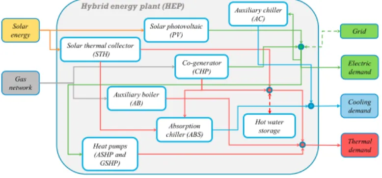
Figure 1 shows a scheme of the HEP considered in this paper. It is composed of different technologies which use renewable and non-renewable energy sources. In particular, solar thermal collector (STC), photovoltaic panel (PV), combined heat and power system (CHP), absorption chiller (ABS), air source heat pump (ASHP), ground source heat pump (GSHP) and thermal energy storage are considered.
Solar photovoltaic (PV) Solar thermal collector
(STH) Co-generator (CHP) Auxiliary boiler (AB) Heat pumps (ASHP and GSHP) Hot water storage Solar energy Gas network Grid Electric demand Thermal demand
Hybrid energy plant (HEP)
Absorption chiller (ABS) Cooling demand Auxiliary chiller (AC)
Fig. 1. Scheme of the HEP
In addition, a condensing boiler (AB) and a chiller (AC) are also considered as auxiliary systems in order to meet thermal and cooling demands in the case that they are not fulfilled by the abovementioned systems. Heat pumps are assumed reversible, i.e. they can produce thermal energy in winter and cooling energy in summer.
Equations (1), (2) and (3) express the balance of thermal energy, cooling energy and electric energy demands to be met by the different technologies of the HEP:
STC,th CHP,th GSHP,th ASHP,th storage,th
thth
AB, E E E E E E
E (1)
ABS,cold GSHP,cold ASHP,cold
cold cold AC, E E E E E (2) el grid, el CHP, el PV, el AC, el ASHP, el GSHP, el E E E E E E E (3)As can be seen from Eq. (1), Eth, which represents the space heating and hot water demand, can be met by the
STC, CHP, GSHP and ASHP systems. The AB ensures the fulfillment of the thermal demand in case it is not met by the other systems. From Eq. (2), Ecold, which represents the cooling demand, is fulfilled by the ABS, GSHP and
ASHP systems. The AC ensures the fulfillment of the cooling demand if not fulfilled by the other systems. The
4 Author name / Energy Procedia 00 (2018) 000–000
electric demand Eel and the electricity required by the heat pumps and the auxiliary chiller are provided by the PV
and CHP systems. If these systems are not able to fulfill the demand of electric energy, the remaining part is imported from the grid. Otherwise, the excess of the produced electric energy from the CHP and the PV is exported to the grid.
A model is implemented in Matlab® environment to simulate the system throughout an entire year on an hourly
basis. The control logic of the different technologies is defined by a switch-on priority mapping which defines the starting order and allows the minimization of the primary energy consumption during the selected simulation period
[9]. More details are provided in a previous work carried out by the authors [10].
Equation (4) defines the primary energy consumed during the operation phase. It is defined as the sum of primary energy consumption of the CHP, AB and the primary energy referred to the electricity exchanged with the grid. The disposal phase is omitted in this study because of lack of data.
sent el, taken el, E E AB fuel, CHP fuel, op PE PE PE PE PE (4)
2.2. Life cycle assessment model
In order to evaluate the primary energy consumed during the manufacturing phase of the PV, STC, CHP, GSHP, ASHP, ABS and the storage, a cradle-to-gate life cycle assessment is carried out. AB and AC are not assessed, since they are considered as auxiliary systems and they are not involved in the optimization process.
The life cycle inventories of the investigated systems were obtained from Ecoinvent® [11] by considering the
European market. The calculation is conducted by using the software openLCA® [12]. The cumulative energy
demand (CED) is considered as the impact indicator. The CED accounts for the primary energy consumed throughout the cradle-to-gate life cycle and represents the depletion of energy resources associated with the life cycle of the system [13].
For sizing optimization purposes, in order to calculate the CED of a system of an arbitrary size, CED values should be available at different sizes of the considered system. However, life cycle inventory databases usually provide inventory data for a certain product at a predefined size. In literature, this problem is usually overcome by scaling linearly the life cycle inventory flows of an equipment with its capacity. Nevertheless, linearization may over- or under- estimate the final results because the relationship between life cycle inventory flows (or impacts) and system size is not linear and follows a power law trend, in a fashion similar to the economies of scale [14]. Thus, to calculate the CED of a system in a range of sizes, life cycle inventory data were scaled as in Eq. (5):
k P P G G ref ref. (5)
where G represents the scaled life cycle inventory flows (i.e. material, energy, emission, etc.) at the scaled size P,
Gref the flows at a reference size Pref and k the scaling exponent which ranges from 0 to 1. The LCI flows (Gref) at
the reference size are obtained from the Ecoinvent® database, while the scaling exponent (k) is derived from
literature. It should be mentioned that, nonlinear scaling was only carried out for the CHP, GSHP, ASHP, ABS and storage equipment, while the LCI of STC and PV systems was scaled linearly (i.e. k=1) as a function of the respective area. Scaling exponents k for the CHP, GSHP, ASHP, ABS were obtained from literature or by assuming the economy of scale. Moreover, in order to calculate the primary energy associated with the manufacturing of the grid, the Italian grid was also modelled by using the Ecoinvent® database. The CED associated with the
cradle-to-gate life cycle of the optimized technologies is calculated as in Eq. (6):
) ( ) ( taken grid s s s s CED El N P CED CED
(6)where CED represents the total CED expressed in MJeq per year, the first term on the right hand-side is the sum
of the primary energy associated with the cradle-to-gate life cycle of the optimized systems and CEDgrid represents
P decision variable or nominal power storage thermal storage PE primary energy consumption taken taken from the grid PV photovoltaic system th thermal
ref reference V volume
2. Model development
The optimal design of the HEP is made by considering an energy-based criterion, i.e. the primary energy consumed throughout the manufacturing and operation phases is minimized. However, a different objective function, such as pollutant emission production or total cost, may be implemented in the model developed in this paper. Sizing optimization is conducted by using a Genetic Algorithm (GA) because of its ability to deal with discrete spaces and solve nonlinear problems [8]. In fact, this kind of evolutionary algorithms does not require limiting assumptions about the underlying objective function.
2.1. Hybrid energy plant
Figure 1 shows a scheme of the HEP considered in this paper. It is composed of different technologies which use renewable and non-renewable energy sources. In particular, solar thermal collector (STC), photovoltaic panel (PV), combined heat and power system (CHP), absorption chiller (ABS), air source heat pump (ASHP), ground source heat pump (GSHP) and thermal energy storage are considered.
Solar photovoltaic (PV) Solar thermal collector
(STH) Co-generator (CHP) Auxiliary boiler (AB) Heat pumps (ASHP and GSHP) Hot water storage Solar energy Gas network Grid Electric demand Thermal demand
Hybrid energy plant (HEP)
Absorption chiller (ABS) Cooling demand Auxiliary chiller (AC)
Fig. 1. Scheme of the HEP
In addition, a condensing boiler (AB) and a chiller (AC) are also considered as auxiliary systems in order to meet thermal and cooling demands in the case that they are not fulfilled by the abovementioned systems. Heat pumps are assumed reversible, i.e. they can produce thermal energy in winter and cooling energy in summer.
Equations (1), (2) and (3) express the balance of thermal energy, cooling energy and electric energy demands to be met by the different technologies of the HEP:
STC,th CHP,th GSHP,th ASHP,th storage,th
thth
AB, E E E E E E
E (1)
ABS,cold GSHP,cold ASHP,cold
cold cold AC, E E E E E (2) el grid, el CHP, el PV, el AC, el ASHP, el GSHP, el E E E E E E E (3)As can be seen from Eq. (1), Eth, which represents the space heating and hot water demand, can be met by the
STC, CHP, GSHP and ASHP systems. The AB ensures the fulfillment of the thermal demand in case it is not met by the other systems. From Eq. (2), Ecold, which represents the cooling demand, is fulfilled by the ABS, GSHP and
ASHP systems. The AC ensures the fulfillment of the cooling demand if not fulfilled by the other systems. The
electric demand Eel and the electricity required by the heat pumps and the auxiliary chiller are provided by the PV
and CHP systems. If these systems are not able to fulfill the demand of electric energy, the remaining part is imported from the grid. Otherwise, the excess of the produced electric energy from the CHP and the PV is exported to the grid.
A model is implemented in Matlab® environment to simulate the system throughout an entire year on an hourly
basis. The control logic of the different technologies is defined by a switch-on priority mapping which defines the starting order and allows the minimization of the primary energy consumption during the selected simulation period
[9]. More details are provided in a previous work carried out by the authors [10].
Equation (4) defines the primary energy consumed during the operation phase. It is defined as the sum of primary energy consumption of the CHP, AB and the primary energy referred to the electricity exchanged with the grid. The disposal phase is omitted in this study because of lack of data.
sent el, taken el, E E AB fuel, CHP fuel, op PE PE PE PE PE (4)
2.2. Life cycle assessment model
In order to evaluate the primary energy consumed during the manufacturing phase of the PV, STC, CHP, GSHP, ASHP, ABS and the storage, a cradle-to-gate life cycle assessment is carried out. AB and AC are not assessed, since they are considered as auxiliary systems and they are not involved in the optimization process.
The life cycle inventories of the investigated systems were obtained from Ecoinvent® [11] by considering the
European market. The calculation is conducted by using the software openLCA® [12]. The cumulative energy
demand (CED) is considered as the impact indicator. The CED accounts for the primary energy consumed throughout the cradle-to-gate life cycle and represents the depletion of energy resources associated with the life cycle of the system [13].
For sizing optimization purposes, in order to calculate the CED of a system of an arbitrary size, CED values should be available at different sizes of the considered system. However, life cycle inventory databases usually provide inventory data for a certain product at a predefined size. In literature, this problem is usually overcome by scaling linearly the life cycle inventory flows of an equipment with its capacity. Nevertheless, linearization may over- or under- estimate the final results because the relationship between life cycle inventory flows (or impacts) and system size is not linear and follows a power law trend, in a fashion similar to the economies of scale [14]. Thus, to calculate the CED of a system in a range of sizes, life cycle inventory data were scaled as in Eq. (5):
k P P G G ref ref. (5)
where G represents the scaled life cycle inventory flows (i.e. material, energy, emission, etc.) at the scaled size P,
Gref the flows at a reference size Pref and k the scaling exponent which ranges from 0 to 1. The LCI flows (Gref) at
the reference size are obtained from the Ecoinvent® database, while the scaling exponent (k) is derived from
literature. It should be mentioned that, nonlinear scaling was only carried out for the CHP, GSHP, ASHP, ABS and storage equipment, while the LCI of STC and PV systems was scaled linearly (i.e. k=1) as a function of the respective area. Scaling exponents k for the CHP, GSHP, ASHP, ABS were obtained from literature or by assuming the economy of scale. Moreover, in order to calculate the primary energy associated with the manufacturing of the grid, the Italian grid was also modelled by using the Ecoinvent® database. The CED associated with the
cradle-to-gate life cycle of the optimized technologies is calculated as in Eq. (6):
) ( ) ( taken grid s s s s CED El N P CED CED
(6)where CED represents the total CED expressed in MJeq per year, the first term on the right hand-side is the sum
of the primary energy associated with the cradle-to-gate life cycle of the optimized systems and CEDgrid represents
2838 Hilal Bahlawan et al. / Energy Procedia 158 (2019) 2834–2840Author name / Energy Procedia 00 (2018) 000–000 5
per year of operation. Finally, for each system, the variables Ns and Ps represent the useful lifetime and the decision
variable (or the size), respectively.
2.3. Optimization method
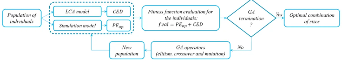
The methodology for sizing optimization of HEPs is outlined in Fig. 2. The GA is initialized by generating a random population of individuals in the design space and each individual represents a combination of sizes of the technologies composing the HEP.
For each individual of the population, the primary energy PEop consumed during the operation phase is calculated
from the simulation model of the HEP as reported in Eq. (4), while the CED is calculated from the LCA model according to Eq. (6).
Population of individuals
Simulation model
Fitness function evaluation for the individuals: GA termination ? GA operators
(elitism, crossover and mutation) New population Optimal combination of sizes Yes No LCA model
Fig. 2. GA optimization flowchart
Consequently, the GA evaluates the fitness function of each individual in the current population as follows:
CED PE
P f
fval ( ) op (7)
Then, based on the values of the individuals in the current population, the GA creates a new population by applying three operators (elitism, crossover and mutation). These mechanisms are repeated by the GA until a certain criterion is met and the best individual, which represents the optimal combination of sizes, is selected.
The decision variables P which represent the sizes of the technologies to be optimized are PCHP,el,nom, PGSHP,th,nom,
PASHP,th,nom, PABS,th,nom, ASTC and APV. The volume of the storage Vstorage is calculated according to [15] as a function
of CHP and STC decision variables, while the size of AB and AC are imposed equal to the peak of the thermal and cooling energy demands, respectively.
3. Results
A tower composed of thirteen floors with commercial and office spaces use, located in the northern Italy, is considered as a case study. The heating, cooling and hot water building energy demands were calculated by using the software EdilClimaEC700®. The energy demand is estimated equal to 207.17 MWh/year for space heating,
154.83 MWh/year for space cooling, 8.75 MWh/year for domestic hot water and 410.92 MWh/year for electricity. The hourly demand presents a peak of 234 kW for space heating and hot water, 294 kW for space cooling and 161 kW for electricity.
The sizing optimization problem of the HEP is carried out based on the efficient matching between building energy demands and the energy supplied by the considered technologies, with the aim of minimizing the objective function represented by Eq. (7). The optimization aims to optimize the STC and PV area (ASTC and APV) which can
cover the available total area (328 m2), the CHP nominal electric power (PCHP,el,nom), which is an integer in the range
0-100 kWe, the GSHP and ASHP nominal thermal power (PGSHP,th,nom and PASHP,th,nom) in the range 0-250 kWth and
the ABS nominal thermal power (PABS,th,nom) in the range 0-200 kWth. It has to be mentioned that, the constraints
related to technology sizes currently available in the market are not taken into account. However, for each technology, they may be considered by adding a constraint on the available maximum and minimum size. Regarding the GA set-up, 300 generations with a population of 300 individuals for each generation are evaluated and the elite count is set equal to 10.
6 Author name / Energy Procedia 00 (2018) 000–000
Table 1 shows the optimization results of the two approaches considered in this study. The first approach (LCA integrated) optimizes the sizes of the technologies by accounting for the primary energy consumed throughout the cradle-to-gate life cycle of these systems, while in the second approach (LCA not integrated) the LCA is not integrated into the optimization process.
As can be seen, the integration of the LCA may lead to a different combination of sizes. In fact, by adding the off-site primary energy consumption evaluated by the LCA method, the area of the PV system increases in favor of the STC of about 13 m2, the size of the CHP is increased from 84 kWe to 100 kWe, the size of the GSHP is halved,
the size of the ASHP increases from 86 to 101 kWth and the ABS nominal power increases from 171 to 200 kWth.
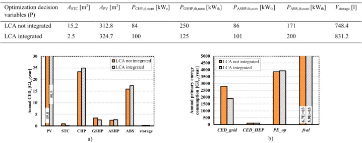
Figure 3.a reports the annual CEDs associated with the cradle-to-gate life cycle of the two combinations of technology sizes (see Table 1) per one-year lifetime obtained by applying the two approaches.
Table 1. Optimal sizes of the technologies Optimization decision
variables (P) ASTC [m
2] APV [m2] PCHP,el,nom [kWe] PGSHP,th,nom [kWth] PASHP,th,nom [kWth] PABS,th,nom [kWth] Vstorage [l]
LCA not integrated 15.2 312.8 84 250 86 171 748.4
LCA integrated 2.5 324.7 100 125 101 200 831.2
a) b)
Fig. 3. Annual CED of the different technologies a) and contribution of the grid, HEP and operation phase to the primary energy consumption b)
With reference to the CED of the GSHP (Fig. 3.a), it can be noted that, even if the size of the GSHP is halved from “LCA not integrated” approach to “LCA integrated” approach, the value of the CED is not halved; this is due to the nonlinear scaling approach adopted in this paper. Indeed, this justifies that linear scaling may under- or over- estimate LCA results and affect the optimization results.
Figure 3.b shows the primary energy associated with the grid (CEDgrid), the cradle-to-gate life cycle of the whole
plant (CEDHEP), the operation phase (CEDop) and the total primary energy consumption (fval). It can be seen that
CEDgrid most heavily affects the optimization results. It should be mentioned that CEDgrid can be evaluated only by
considering both the LCA and the operation. This is due to the fact that CEDgrid is related to the electricity taken
from the grid which depends on the operation policy of the different technologies. Furthermore, by integrating LCA into sizing optimization, the GA algorithm tends to increase the PV area in favor of the STC and also increases the size of the CHP, in order to minimize the amount of electricity taken from the grid. Moreover, the integration of LCA leads to a primary energy saving of about 12%.
4. Conclusions
The problem of optimal sizing of a HEP by accounting for off-site primary energy consumption was investigated in this paper. The problem of nonlinear scaling of the LCI of the different technologies was also addressed. Two approaches were evaluated in order to evaluate the influence of the integration on the optimal result and plant configuration. The main conclusion of this paper is that accounting for off-site primary energy consumption may
49 .0 50. 9 0 5 10 15 20 25 30
PV STC CHP GSHP ASHP ABS storage
A nnua l C E Ds [G Jeq /ye ar ]
LCA not integrated LCA integrated 6. 7E +03 5. 9E +03 0 500 1000 1500 2000 2500 3000 3500 4000 4500 5000
CED_grid CED_HEP PE_op fval
A nn ual p ri m ar y e ne rgy con su m pti on [G Jeq /ye ar
per year of operation. Finally, for each system, the variables Ns and Ps represent the useful lifetime and the decision
variable (or the size), respectively.
2.3. Optimization method
The methodology for sizing optimization of HEPs is outlined in Fig. 2. The GA is initialized by generating a random population of individuals in the design space and each individual represents a combination of sizes of the technologies composing the HEP.
For each individual of the population, the primary energy PEop consumed during the operation phase is calculated
from the simulation model of the HEP as reported in Eq. (4), while the CED is calculated from the LCA model according to Eq. (6).
Population of individuals
Simulation model
Fitness function evaluation for the individuals: GA termination ? GA operators
(elitism, crossover and mutation) New population Optimal combination of sizes Yes No LCA model
Fig. 2. GA optimization flowchart
Consequently, the GA evaluates the fitness function of each individual in the current population as follows:
CED PE
P f
fval ( ) op (7)
Then, based on the values of the individuals in the current population, the GA creates a new population by applying three operators (elitism, crossover and mutation). These mechanisms are repeated by the GA until a certain criterion is met and the best individual, which represents the optimal combination of sizes, is selected.
The decision variables P which represent the sizes of the technologies to be optimized are PCHP,el,nom, PGSHP,th,nom,
PASHP,th,nom, PABS,th,nom, ASTC and APV. The volume of the storage Vstorage is calculated according to [15] as a function
of CHP and STC decision variables, while the size of AB and AC are imposed equal to the peak of the thermal and cooling energy demands, respectively.
3. Results
A tower composed of thirteen floors with commercial and office spaces use, located in the northern Italy, is considered as a case study. The heating, cooling and hot water building energy demands were calculated by using the software EdilClimaEC700®. The energy demand is estimated equal to 207.17 MWh/year for space heating,
154.83 MWh/year for space cooling, 8.75 MWh/year for domestic hot water and 410.92 MWh/year for electricity. The hourly demand presents a peak of 234 kW for space heating and hot water, 294 kW for space cooling and 161 kW for electricity.
The sizing optimization problem of the HEP is carried out based on the efficient matching between building energy demands and the energy supplied by the considered technologies, with the aim of minimizing the objective function represented by Eq. (7). The optimization aims to optimize the STC and PV area (ASTC and APV) which can
cover the available total area (328 m2), the CHP nominal electric power (PCHP,el,nom), which is an integer in the range
0-100 kWe, the GSHP and ASHP nominal thermal power (PGSHP,th,nom and PASHP,th,nom) in the range 0-250 kWth and
the ABS nominal thermal power (PABS,th,nom) in the range 0-200 kWth. It has to be mentioned that, the constraints
related to technology sizes currently available in the market are not taken into account. However, for each technology, they may be considered by adding a constraint on the available maximum and minimum size. Regarding the GA set-up, 300 generations with a population of 300 individuals for each generation are evaluated and the elite count is set equal to 10.
Table 1 shows the optimization results of the two approaches considered in this study. The first approach (LCA integrated) optimizes the sizes of the technologies by accounting for the primary energy consumed throughout the cradle-to-gate life cycle of these systems, while in the second approach (LCA not integrated) the LCA is not integrated into the optimization process.
As can be seen, the integration of the LCA may lead to a different combination of sizes. In fact, by adding the off-site primary energy consumption evaluated by the LCA method, the area of the PV system increases in favor of the STC of about 13 m2, the size of the CHP is increased from 84 kWe to 100 kWe, the size of the GSHP is halved,
the size of the ASHP increases from 86 to 101 kWth and the ABS nominal power increases from 171 to 200 kWth.
Figure 3.a reports the annual CEDs associated with the cradle-to-gate life cycle of the two combinations of technology sizes (see Table 1) per one-year lifetime obtained by applying the two approaches.
Table 1. Optimal sizes of the technologies Optimization decision
variables (P) ASTC [m
2] APV [m2] PCHP,el,nom [kWe] PGSHP,th,nom [kWth] PASHP,th,nom [kWth] PABS,th,nom [kWth] Vstorage [l]
LCA not integrated 15.2 312.8 84 250 86 171 748.4
LCA integrated 2.5 324.7 100 125 101 200 831.2
a) b)
Fig. 3. Annual CED of the different technologies a) and contribution of the grid, HEP and operation phase to the primary energy consumption b)
With reference to the CED of the GSHP (Fig. 3.a), it can be noted that, even if the size of the GSHP is halved from “LCA not integrated” approach to “LCA integrated” approach, the value of the CED is not halved; this is due to the nonlinear scaling approach adopted in this paper. Indeed, this justifies that linear scaling may under- or over- estimate LCA results and affect the optimization results.
Figure 3.b shows the primary energy associated with the grid (CEDgrid), the cradle-to-gate life cycle of the whole
plant (CEDHEP), the operation phase (CEDop) and the total primary energy consumption (fval). It can be seen that
CEDgrid most heavily affects the optimization results. It should be mentioned that CEDgrid can be evaluated only by
considering both the LCA and the operation. This is due to the fact that CEDgrid is related to the electricity taken
from the grid which depends on the operation policy of the different technologies. Furthermore, by integrating LCA into sizing optimization, the GA algorithm tends to increase the PV area in favor of the STC and also increases the size of the CHP, in order to minimize the amount of electricity taken from the grid. Moreover, the integration of LCA leads to a primary energy saving of about 12%.
4. Conclusions
The problem of optimal sizing of a HEP by accounting for off-site primary energy consumption was investigated in this paper. The problem of nonlinear scaling of the LCI of the different technologies was also addressed. Two approaches were evaluated in order to evaluate the influence of the integration on the optimal result and plant configuration. The main conclusion of this paper is that accounting for off-site primary energy consumption may
49 .0 50. 9 0 5 10 15 20 25 30
PV STC CHP GSHP ASHP ABS storage
A nnua l C E Ds [G Jeq /ye ar ]
LCA not integrated LCA integrated 6. 7E +03 5. 9E +03 0 500 1000 1500 2000 2500 3000 3500 4000 4500 5000
CED_grid CED_HEP PE_op fval
A nn ual p ri m ar y e ne rgy con su m pti on [G Jeq /ye ar
2840 Hilal Bahlawan et al. / Energy Procedia 158 (2019) 2834–2840Author name / Energy Procedia 00 (2018) 000–000 7
lead to a different configuration of the HEP and to a higher primary energy saving, which in turn means a lower depletion of energy resources and environmental impacts.
References
[1] Varun, I. K. Bhat, Ravi Prakash. LCA of renewable energy for electricity generation systems - A review. Renewable and Sustainable Energy Reviews. 2009; 13:1067-1073.
[2]ISO 14040. Environmental Management – Life Cycle Assessment – Principles and Framework; 1997.
[3] A.S.O Ogunjuyigbe, T.R. Ayodele, O.A. Akinola. Optimal allocation and sizing of PV/Wind/Split-diesel/Battery hybrid energy system for minimizing life cycle cost, carbon emission and dump energy of remote residential building. Applied Energy. 2016; 171:153-171.
[4] R. Dufo-Lòpez, J.L. Bernal-Agustìn, J.M. Yusta-Loyo, J.A. Domìnguez-Navarro, I.J. Ramìrez-Rosado, J. Lujano, I. Aso. Multi-objective optimization minimizing cost and life cycle emissions of stand-alone PV-wind-diesel systems with batteries storage. Applied Energy. 2011; 88:4033-4041.
[5] Y. Jing, H. Bai, J. Wang. Multi-objective optimization design and operation strategy analysis of BCHP system based on life cycle assessment. Energy. 2012; 37:405-416.
[6] Marlos Caduff, Mark A. J. Huijbregts, Hans-Joerg Althaus, A. Jan Hendriks. Power-law relationships for estimating mass, fuel consumption and costs of energy conversion equipments. Environmental Science & Technology. 2011; 45:751-754.
[7] Moore, F. T. Economies of scale: Some statistical evidence. Q. J. Econ. 1959; 73 (2): 232–245. [8] A. Messac, Optimization in Practice with MATLAB®, Cambridge University Press, 2015.
[9] E.S. Barbieri, M. Morini, E. Munari, M. Pinelli, P.R. Spina, R. Vecci, Concurrent optimization of size and switch-on priority of a multi-source energy system for a commercial building application, Energy Procedia 81 (2015) 45-54.
[10] E.S. Barbieri, Y.J. Dai, M. Morini, M. Pinelli, P.R. Spina, P. Sun, R.Z Wang, Optimal sizing of a multi-source energy plant for power heat and cooling generation, Applied Thermal Engineering 71 (2014) 736-750.
[11] EMPA. EcoInvent. Switzerland: EcoInvent; 2007.
[12] OpenLCA 1.6.3, GreenDelta. Source: http://www.openlca.org.
[13] Rolf Frischknecht, Franziska Wyss, Sybille Busser Knopfel, Thomas Lutzkendorf, Maria Balouktsi. Cumulative energy demand in LCA: the energy harvested approach. Int. J. LCA. 2015; 20:957-969.
[14] M. Caduff, M. A.J. Huijbregts, A. Koehler, H.J. Althaus, S. Hellweg. Scaling Relationships in Life Cycle Assessment: The case of heat production from biomass and heat pumps. Journal of Industrial Ecology. 2014; 18:393–406.