Universit`
a di Pisa
Dipartimento di Ingegneria
dell’Informazione
Elettronica, Informatica, Telecomunicazioni
Tesi di Dottorato di Ricerca in
Ingegneria dell’Informazione
XIX ciclo
Traffic Control and Quality of Service in
Wireless LANs
Candidato Tutori
Luca Tavanti Prof. Franco Russo Prof. Stefano Giordano Ing. Rosario G. Garroppo
Acknowledgements
The author would like to thank Thales Italia S.p.A, which kindly sponsored his PhD scholarship, thus allowing the realisation of this work.
Contents
Contents v
Introduction 1
1 The IEEE 802.11: concepts and performance 7
1.1 Basics of IEEE 802.11 . . . 9
1.1.1 The e amendment to the standard . . . 12
1.2 Performance evaluation of 802.11a/b/g . . . 15
1.2.1 The performance anomaly . . . 18
1.3 Performance evaluation of 802.11e . . . 19
2 The Deficit Transmission Time scheduler 23 2.1 A different vision of fairness . . . 25
2.2 The Deficit Transmission Time scheduler . . . 27
2.2.1 Description of DTT . . . 28
2.2.2 An insight into DTT features . . . 30
2.2.3 Prototype implementation . . . 32
2.2.3.1 Description of the prototype AP . . . 32
2.2.3.2 The experimental testbed . . . 34
2.2.3.3 Analysis of the results . . . 36
2.2.4.1 The E-model . . . 46
2.2.4.2 The simulation environment . . . 47
2.2.4.3 Simulation results . . . 51
2.3 The Distributed DTT scheduler . . . 56
2.3.1 Description of (DT)2 . . . . 57
2.3.2 (DT)2 for VoIP applications . . . 61
2.3.2.1 Topology and settings . . . 63
2.3.2.2 Performance analysis . . . 65
2.3.2.3 Facing the bottleneck effect . . . 68
2.4 Conclusions . . . 70
3 Admission Control in IEEE 802.11e Networks 73 3.1 The Admission Region . . . 75
3.1.1 Criteria for estimating the Admission Region . . . 75
3.1.2 Simulation framework . . . 77
3.1.3 Analysis of the results . . . 79
3.2 Model-Based Admission Control . . . 82
3.2.1 The admission control algorithm . . . 83
3.2.2 The reference model . . . 87
3.2.3 Application to a VoIP scenario . . . 89
3.3 Measure-Based Admission Control . . . 93
3.3.1 Overview of the NUC . . . 94
3.3.2 Extending the NUC to 802.11e . . . 95
3.3.3 Application to voice and video . . . 100
3.3.3.1 Simulation results . . . 101
3.4 Conclusions . . . 109
4 Conclusions 111
Introduction
The IEEE 802.11 standard has rapidly become the most popular technol-ogy for broadband wireless local area networks (WLANs). As a corollary, we have seen a steep rise in the efforts to increase system capacity to satisfy Internet users’ hunger for bandwidth. This led to the ratification of the a, b and g amendments to the standard, which allow rates up to 54 Mbps, and to the pursue of enhancements to further increase the maximum data rate (Task Group n). More lately, the growth of multimedia services over the “wired” Internet has give strength to the idea of supporting real-time applications over wireless LANs too. However, it has also become evident that even the latest versions (a, b, and g), with the sole use of more ef-ficient modulation schemes and/or other frequency bands, can hardly be employed to offer adequate support to services with strict Quality of Service (QoS) requirements, as they do not provide any means to guarantee the timely and reliable delivery of frames1. The IEEE 802.11 working group
has therefore issued the new e amendment which defines some mechanisms for differentiating the traffic on the basis of the priority in accessing the radio channel. In this way, the IEEE intended to complement the 802.11 standard suite in order to let it satisfactorily support any kind of service.
1Actually, the PCF mode was originally conceived with this purpose; in practice, however, manufacturers never released commercial products supporting this mode.
Yet, this goal has been only partially accomplished, as 802.11 systems still present several drawbacks.
One of the most critical factors driving the efficiency of these networks is the ability to overcome the hurdles imposed by the wireless channel. The actually exploitable capacity of the links is highly variable in both time and space, thus leading to unpredictable frame delivery ratio and delays. In addition, the heterogeneity of the terminals and the possible use of multiple transmission rates are factors that may limit the overall system throughput. The same 802.11 Distributed Coordination Function (DCF, the basic and most employed operation mode) does not deal effectively with this problem. In fact, when employed in the above mentioned conditions, it often leads to the so called “performance anomaly”. When this phenomenon occurs, the throughput of all the stations tends to align to that of the slowest station in the network. Moreover, the unique First-In First-Out (FIFO) queue commonly implemented at the Access Point (AP) creates an undesirable inter-dependence (in terms of delays) of traffic flows addressed to different stations. The overall efficiency loss is thus apparent.
A solution to these problems has been reckoned to reside in a smart scheduling algorithm to be deployed at the AP. In fact, several schedulers for wireless networks have already been proposed in literature. In most cases, however, these solutions rely on a model of the wireless channel. This has the drawback to be more or less distant from the actual channel be-haviour, thus making the scheduler inefficient or unfeasible. Consequently, a more reliable solution would be centring scheduling decisions on a real measure of the state of the links.
Starting from these observations, we have designed and developed a sim-ple scheduling algorithm to take into account the actual channel behaviour. The main innovation of our scheduler is the way it measures link quality. This is not appraised with usual metrics, such as signal-to-noise ratio, but is
Introduction quantified as the time needed to deliver a frame to the destination. Hence, the resource to share is not the total capacity of the channel, but the time the channel is in use. This is the actualisation of a different fairness idea, named proportional fairness. We show that this approach leads to noteworthy improvements, and in particular we show how it is possible to isolate the flows from each other, so that each flow can take advantage of its channel share irrespectively of the quality experimented by the others. This algorithm has been implemented and tested through simulations and, above all, on a prototype AP. To the best of our knowledge, this is the first working implementation of a scheduler realising proportional fairness.
The second part of this thesis deals with the interesting issue of trans-porting real-time services over 802.11e networks. The recent e amendment specifies the rules to realise traffic differentiation in wireless LANs. The ba-sic philosophy is to give quicker access to medium to high priority traffic, i.e. traffic that is more sensitive to delay. While there is broad consensus about its fair capability to support real-time applications with a reasonable qual-ity, it has also been shown that this capability is extremely limited. 802.11e provides less predictable performance than a reservation based method and suffers from network congestion. Scarce reliability of QoS guarantees, star-vation of low priority traffic and unbalanced uplink/downlink bandwidths are the most serious drawbacks hampering its use. For these reasons, it can be argued that the support of QoS cannot be easily achieved if disjoint from the relevant issue of admission control (in short, a.c.). In detail, an algorithm must be run to determine the maximum number of users/services that can be admitted to the network while satisfying the respective QoS requirements.
Our activity in this field started with the determination of the admission region for voice and video in a 802.11e WLAN. The number of videocon-ference and VoIP sources that can be accepted in the 802.11e coverage
area has been evaluated, in presence of TCP traffic, considering the actual QoS requirements that can be assumed for these services. This preliminary study casts light on two aspects. On one hand transport differentiation is fairly efficiency as delay-sensitive traffic is scarcely influenced by low prior-ity services. On the other hand, it has emerged the presence of a bottleneck at the AP queue. Hence the admission region turned out to be dependent almost exclusively on the streams towards the mobile stations.
Then we devised two admission control algorithms. In both cases the ad-mission test is based on the time occupancy of the medium, but they differ in the way they compute it. As learned from previous research on the above mentioned scheduler, this metric turned out to be simple and very efficient. The first algorithm exploits an analytical model of the EDCA (Enhanced Distributed Channel Access) mode in non-saturation conditions. The use of this model, above all in the non-saturation part, allows to overcome the limits of previous works, based on saturation models. As shown in the study on the admission region, the non-saturation hypothesis closely matches the real state of the network when the interest is on time-sensitive applications. The second algorithm uses a parameter already defined, and very effective, for 802.11b systems. So, we have extended it in order to make it applicable to 802.11e networks. Differently from the first method, this scheme bases on measurements on the state of the network.
As a final remark, we would like to put some emphasis on the method we chose to evaluate our algorithms. In most cases the proposed models have been tested through simulations, and the majority of the performance tests reported in the thesis involves networks supporting voice services. In this context, the widely adopted measure of throughput, delay, and/or packet losses can only give a rough estimate of the goodness of the service. It is well known that subjective factors, like human perception of voice quality, should also be taken into account. For this reason, we have decided to take
Introduction advantage of the E-model, which is a specialised framework standardized by the ITU-T. The E-model translates the perceived speech quality into a single scalar value, which is computed not only from the measure of delay and packet losses, but also from the characteristics of the network and terminal equipment and the expectation of the average user. Therefore, for voice-oriented applications, this tool provides much more comprehensive and accurate performance measures than traditional metrics.
The thesis is organised as follows. At first, in Chapter1, a brief overview of the IEEE 802.11 standard is given, with reference to both the basic and the enhanced (802.11e) access. A short review of the related liter-ature is also reported, with particular attention to the topics subject of our work (i.e. performance anomaly, analytical models, admission con-trol). Then, Chapter 2 presents the scheduler we designed to face the performance anomaly, together with simulation and experimental results. Admission control is the subject of Chapter 3, which describes the study on the admission region and the two admission control schemes. Finally, the conclusions can be found in Chapter 4.
Chapter 1
The IEEE 802.11: concepts
and performance
In 1997, the Institute of Electrical and Electronics Engineers (IEEE) adopted the first wireless local area network WLAN standard, named IEEE 802.11. Initially provided with data rates of 1 and 2 Mbps, it did not receive an immediate market favour, mainly because of the difficulties in realising the interoperability between products from different vendors. Hence the IEEE created several task groups (TG) to supplement and improve these early specifications. In particular, task group b issued an amendment for backward compatible operations in the 2.4 GHz band with data rates up to 11 Mbps. The revised 802.11 standard [1], published in 1999 and of-ten referred to as Wireless Fidelity (Wi-Fi), has then become an overnight success, turning the IEEE 802.11 into the de facto standard for wireless LANs. Further extensions of the standard followed, leading to even higher data rates: the a and g versions offer 54 Mbps in the 5 GHz and 2.4 GHz bands, and the still active task group n aims at reaching 108 Mbps. In parallel, other groups have been working on traffic differentiation (TGe), security (TGi), vehicle communications (TGp), mesh networking (TGs),
and so on.
As it often happens, the activities of the standardization body are be-ing complemented by work from research centres and universities, whose typical outcome is the evaluation of the effectiveness of the mechanisms specified in the standards, as well as the proposal of further improvements. This has generated an ever increasing number of papers dealing with the 802.11 standard in all its flavours. These studies have pointed out several performance problems. Some weird behaviours and anomalies have also been reported.
At present, one of the most challenging tasks is the support of real time multimedia applications. It is by now plain that the sole use of more effi-cient modulation schemes and/or other frequency bands is not suffieffi-cient to offer adequate support to applications that have strict Quality of Service (QoS) requirements, such as Voice over IP (VoIP), video streaming or other delay (or bandwidth) sensitive applications. The same IEEE, aware of the unsuitability of the basic 802.11 standard, and given the increasing influ-ence of these services, has recently ratified the e amendment to the standard [2]. 802.11e offers service differentiation to various classes of traffic, grant-ing delay sensitive applications (e.g. voice and video) higher priority in accessing the channel. Though it has indeed improved the support of real-time services, yet no strict guarantee is given in terms of QoS parameters. A conspicuous number of works has already assessed the performance and proposed enhancements to this amendment.
In this Chapter a brief overview of the IEEE 802.11 standard is given. At first, the basic features and operations are described, for both the legacy version and the new e version. 802.11 essentially supports two modes of operation, distributed and centralised. Since the latter has received scarce attention by both researchers and, above all, manufacturers, we will focus mostly on the former. Then, a short scan of the literature dealing with
1.1 Basics of IEEE 802.11 performance evaluation of both version we will be given. A particular emphasis will be put on the performance anomaly problem.
1.1
Basics of IEEE 802.11
The IEEE 802.11 standard defines two methods to access the wireless chan-nel: the Distributed Coordination Function (DCF) and the Point Coordi-nation Function (PCF). The former is based on CSMA/CA (Carrie Sense Multiple Access with Collision Avoidance) and let the terminals contend for the access to the medium. So it can only offer a best effort service. On the contrary the latter supplies polled access via arbitration by a Point Coordinator, which resides in the Access Point. PCF was meant to be used for applications requiring time-bounded frame delivery. In practice, how-ever, PCF failed to deliver its promises, and has never been implemented by manufacturers. Therefore we will no longer deal with it. Describing the reasons of this failure is out of the scope of this thesis. The interested reader may refer to [1].
According to DCF rules, a station1 wishing to transmit a frame shall
sense the channel for a given period of time (called DIFS — Distributed Inter Frame Space). If the medium is sensed idle for the whole DIFS, the station is allowed to transmit. Otherwise the station shall wait until the medium becomes idle and then enter a collision avoidance phase. This phase consists in executing the exponential backoff algorithm. The station picks a random integer value from the interval [0, CW] to initialise a backoff counter. This interval is the so-called contention window. CW may vary between CWmin, which is the first assigned value, and CWmax. Then the
host starts sensing the medium and, again after a DIFS, decrements the
1In this thesis, the terms “station” and “host” will be interchangeably used to refer to terminals equipped with an 802.11 card.
Figure 1.1: An example of 802.11 basic access
counter by one for each time unit (or SLOT) the medium is sensed idle. If the medium becomes busy the countdown must be suspended; it can be restarted only when the medium is idle again. When the counter reaches zero, the station is allowed to transmit. A graphic summary of this rules is reported in Figure 1.1.
When a frame (other than broadcast) is correctly received, the receiving host shall send an ACK frame after another fixed period of time called SIFS (Short IFS). As the name suggests, this is shorter than DIFS to allow the ACK to immediately follow the frame which it refers to. If the sending host does not receive an ACK within a specified timeout, it must assume the transmission has failed. As a consequence it must increase the retry counter for that frame. If this counter has reached the Maximum Retry Limit (MRL) threshold, the frame shall be discarded and a new transmission cycle may begin. Otherwise, the station must start a new backoff cycle with a quasi-doubled CW. The exact rule is CWnew = 2(CWold+ 1) − 1.
CW is upper-bounded by CWmax. CW is reset to CWmin at the beginning
of every transmission cycle, i.e. after either a success or a discarded frame due to the exceeded retry limit.
To overcome the problem of hidden terminals, the standard provides the optional RTS/CTS mechanism. The sending host shall at first transmit a short RTS (Request To Send) frame, following the same access rules
1.1 Basics of IEEE 802.11 described before. When the destination hears the RTS it must respond with a CTS (Clear To Send) frame. The sender will then transmit the data frame and wait for the ACK as usual. All these frames are separated by SIFSs to prevent other stations (which shall wait for at least a DIFS) from interrupting the sequence. Moreover, each station hearing either an RTS or a CTS must set and start the so-called Network Allocation Vector (NAV). This timer is initialised with the remaining duration of the whole frame exchange, which is inserted in the control frames by the sender itself. NAV is then decremented down to zero. This mechanism, called virtual carrier sensing, lets every station know when the current transmission ends and therefore prevent them from colliding with possibly hidden stations. Since RTS are usually (much) shorter than data frames, if a collision occurs less time is wasted. However, due to the added overhead, the use of RTS/CTS is advantageous only when data frames are long (in terms of time occupancy of the medium).
Another optional, but widely implemented, feature is the possibility to use several physical data rates in the same network and to adapt these rates to channel conditions. In particular, Automatic Rate Fall-back (ARF) algorithms are employed to scale down the transmission rate to increase the probability of correct reception in case of multiple transmission failures. Amendments b, a, g, and the upcoming n, have introduced data rates up to 108 Mbps. However, to maintain backward compatibility with the first terminals, these speeds can only be used for data frames addressed to stations that explicitly support them. All other frames must be sent at one of the basic rates, i.e. 1 or 2 Mbps. We will see in Section 1.2.1 how these mechanisms, beyond raising the network capacity, are also the cause of one of the most limiting factors of 802.11 systems.
1.1.1
The e amendment to the standard
To introduce some level of Quality of Service (QoS), and to solve part of the coordination problems between PCF and DCF (see e.g. [3] for a brief review on this topic), the 802.11e standard defines a new function called HCF (Hybrid Coordination Function). HCF merges contention-based and controlled medium access into a single protocol. The contention method is called Enhanced Distributed Channel Access (EDCA) and provides relative QoS by differentiating the access priority to the radio channel. The other function is named HCF Controlled Channel Access (HCCA) and supports parameterised QoS through reservation of transmission time.
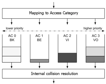
According to EDCA, traffic differentiation occurs exploiting four service classes, denoted as Access Categories (ACs). Every station has also four transmission queues. Thus, as opposed to DCF where all traffic shares a common queue, traffic is assigned to a specific queue on the basis of its QoS requirements. Each AC behaves like a virtual station, contending for the opportunity to transmit independently from the other (see Figure 1.2). The contention rules are the same of DCF, but diverse channel access pa-rameters are used for each queue. If two (or more) ACs within a single station becomes ready to transmit at the same time, an internal collision occurs. The collision is resolved so that the frames with higher priority is actually sent on the channel, whereas the other AC enters into a new backoff phase, as if an external collision has really occurred (but without increasing the retry counter).
Once an AC has gained access to the medium, it is allowed to transmit more than one frame without contending again, provided that the total access time does not exceed a threshold (TXOPLimit). A SIFS is used between every frame in the burst to ensure that no other station interrupts the train. This option, called Transmission Opportunity (TXOP), has been
1.1 Basics of IEEE 802.11
Figure 1.2: The reference implementation model of EDCA
introduced to reduce waste times and thus increase the bandwidth exploita-tion. Note that only the AC that gained the access to medium is entitled to transmit further frames from its queue. Hence, in the context of EDCA, station and AC are not interchangeable terms. In fact, during a TXOP, a station is not allowed to send frames belonging to ACs other than the one that won the TXOP, even though there is time left in the TXOP.
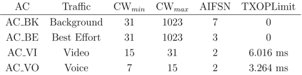
Traffic differentiation is realised through three parameters: the con-tention window (in terms of its bounds CWmin and CWmax), the
inter-frame space and the TXOPLimit. The single DIFS is replaced by four specialised AIFS (Arbitration IFS). Each AIFS is equal to a SIFS plus a number AIFSN[AC] of time slots. Clearly, the higher the priority, the lower the AIFSN. Similarly, TXOPLimit is bigger for high priority ACs. Table 1.1 reports the values of the parameters for the four ACs.
Table 1.1: Default EDCA parameter set — TXOPLimit refers to DSSS physical layer
AC Traffic CWmin CWmax AIFSN TXOPLimit
AC BK Background 31 1023 7 0
AC BE Best Effort 31 1023 3 0
AC VI Video 15 31 2 6.016 ms
AC VO Voice 7 15 2 3.264 ms
The presence of the ACs offers priority in accessing the radio channel, but it does not give any strict QoS guarantee. The actual level of achievable QoS depends on many factors, and among these the traffic load offered to the network is one of the most influencing. In particular, as the network approaches the saturation point, even the highest priority AC is unable to guarantee the required QoS. To overcome this problem, the same 802.11e standard suggests the use of admission control algorithm, whose specifica-tion is left to the manufacturers of the cards. Furthermore, to optimize the functioning of the whole system, the AP can dynamically adjust the contention window and the TXOPLimit for each AC. The new values are advertised in the beacon frames and must be immediately employed by the stations.
The other way of differentiating the service is offered by HCCA, which is designed to properly handle traffic streams with strict QoS requirements. HCCA is based on a polling scheme: the Hybrid Coordinator (HC) polls the stations according to their traffic requests. Since HCCA is not the target of this thesis, we will not deal further with it. We just mention that it seems destined to follow the unlucky faith of PCF, as in the first commercial 802.11e products HCCA is not implemented.
1.2 Performance evaluation of 802.11a/b/g
1.2
Performance evaluation of 802.11a/b/g
In the following, we present an outline of some of the most meaningful works in this area, summarising the achieved results. It is not our goal to give a comprehensive overview of the copious literature in this field. Rather we will focus on the topics that are most related to this thesis.
One of the first papers to evaluate the IEEE 802.11 standard through an analytical approach is [4], which provides a simple and accurate analyt-ical model to compute the throughput of DCF. The key assumption is a constant collision probability, which is not dependent on the number of re-transmissions. The behaviour of each station is modelled as a discrete-time Markov chain. By solving the chain, the author evaluates the asymptotic saturation throughput, which is shown to be dependent on the network size and on the contention window parameters. As the network size is not directly controllable, the only way to achieve optimal performance is to use adaptive techniques to tune the contention window on the basis of the esti-mated network size. However, when the RTS/CTS mechanism is employed, the performance is only marginally dependent on system parameters and throughput benefits even with fairly limited packet sizes.
Another interesting observation found in [4] is that 802.11, like other random access schemes, exhibits some form of instability. As the offered load increases, the throughput at first grows up to a maximum value, then shows a significant decrease. This behaviour translates into the practical impossibility to operate the scheme at its maximum throughput for a long period of time, and thus in the meaningless of the maximum throughput as a performance figure for the access scheme. Comparison with simulation results shows that Bianchi’s model is pretty accurate. Remarkably, this work has been the starting point of most of the successive analytical models. Bianchi himself further refined and corrected it in [5].
The high variability of throughput and delay in 802.11 networks has been revealed by many authors. Ref. [6] is one of the first and still one of the most complete simulation papers. The effects of payload size, chan-nel conditions, and system thresholds (for RTS/CTS and fragmentation) are considered. One of the most evident outcomes is that throughput is heavily affected by all these factors. This result is confirmed in [7], which shows that even in a simple unsaturated network, the standard deviation of throughput is around 42%, while the average and standard deviation of access delay are 1 and 1.2 seconds, respectively. Given these values, the DCF is clearly unsuitable to support QoS applications. Note that this re-sult is easily understandable: many of the parameters regulating the access to the medium introduce random delays while the contention window itself depends on the history of previous attempts. It might also worth noting that newcomers, being their contention window at the minimum value, have higher probability to access the medium than already “collided” stations.
PCF too is shown to present some drawbacks that severely limit its support to time-bounded services [6;8]. In a scenario with mixed data and voice traffic, even assuming rather loose delay bounds, a fair amount of voice frames must be discarded due to an exceeded delivery time. The unpre-dictable beacon delays and the unknown polling instant and transmission time of the polled stations are the most prominent factors of performance degradation. Furthermore, it has been pointed out that all stations in the polling list have the same priority and are polled with same rate, whether they have or not data to transmit. So, PCF is scarcely flexible with respect to different traffic requirements [9].
The authors of [10] and [11] point out that the main cause of the re-duction of throughput with respect to the nominal data rate is constituted by the physical preamble and header, which are always transmitted at the lowest data rate (1 Mbps). Therefore it is particularly relevant when the
1.2 Performance evaluation of 802.11a/b/g transmission of data occurs at higher data rates (e.g. 11 Mbps). Even with large packets sizes, the bandwidth utilization is very low. The val-ues extracted from an analytical formula giving the throughput achievable by a single station generating UDP traffic are compared with the results obtained in an experimental testbed. The results confirm the formula, although in some cases the effective measured throughput is surprisingly slightly higher than the theoretical one. Furthermore, an investigation on packet loss rate as a function of distance at different transmission rates reveals that, especially when using the highest data rates, there is a signif-icant difference in the transmission range of control and data frames. As a consequence, stations reserve the channel for a radius (much) larger than they can actually reach with data [10].
Some performance differences might be expected for the a and g amend-ment to the standard. Both employ the same access method of the plain 802.11 but new physical layer specifications (i.e. Coded Orthogonal Fre-quency Division Multiplexing, COFDM); 802.11a also operates in a differ-ent frequency band. A comparison between these two version is provided by [12] for an indoor scenario. The authors translate a ray-launching propaga-tion model into achievable data rates and hence throughput performance. The result is that 802.11g achieves superior coverage (around 10 percent) thanks to lower signal attenuation at 2.4 GHz, but much lower data rates caused by MAC inefficiency when maintaining backward compatibility with 802.11b.
Summarising, DCF is well suited to support data traffic under light load and with a limited number of stations. That is mainly caused by two factors: first, collisions and random backoff not only constrain the throughput to a limited quota of the nominal bandwidth, but also decrease network capacity as the number of stations increases. Moreover, given the wide fluctuations of throughput and delay, all traffic different from
asynchronous data transfer will be severely impaired by DCF. On the other hand, PCF may be adopted for the delivery of time bounded services only when the requirements, in terms of bandwidth, delay and jitter, are not very stringent. As a matter of fact, the presence of a conspicuous number of terminals with data traffic and different access needs and capacities may seriously abate the PCF effectiveness.
1.2.1
The performance anomaly
A potentially deleterious behaviour has been revealed by Heusse et al. in [13]. The authors observe that when some mobile hosts use a bit rate lower than the others, the performance of all hosts is considerably degraded. This situation is common in wireless local area networks in which a host far from the Access Point is subject to important signal attenuation and interference. To cope with this problem, the host usually down-scales its bit rate to some lower value to exploit more robust modulation schemes. But the same phenomenon may also occur when stations are equipped with cards supporting different data rates (e.g. 802.11b and 802.11g).
The authors derive simple expressions for the useful throughput and val-idate them by means of simulation. They conclude that the basic CSMA/CA channel access method is at the root of this anomaly: it guarantees an equal long term channel access probability to all hosts, thus penalising fast hosts and advantaging slow ones. For example, a host transmitting at 1 Mbps re-duces the throughput of all other hosts transmitting at 11 Mbps to a value below 1 Mbps. The network presents a clear “performance anomaly”: the throughput of all hosts transmitting at the higher rate decays even below the level of the lowest rate. This anomaly holds whatever is the proportion of slow hosts. The question becomes important for hot spots that cover
1.3 Performance evaluation of 802.11e areas with a great number of hosts, when the probability that some mobile hosts suffer poor channel conditions and/or use a lower bit rate is high.
As a final remark, it is worth noting that the performance anomaly, is a direct consequence of the philosophy backing the 802.11 standard. The CSMA/CA medium access strategy coupled with the fairness objective of DCF (max-min throughput fairness) is exactly the cause of this drawback. Hence the anomaly affects the whole 802.11 family, and, in particular, it also affects the recently ratified e amendment. So, real-time services too, even when transported over 802.11e networks, are subject to be heavily spoiled by this phenomenon.
1.3
Performance evaluation of 802.11e
Performance evaluation of 802.11e EDCA has been thoroughly carried out in recent literature1. An analytical model to evaluate saturation
through-put, channel access delay and frame dropping probability for EDCA was proposed by Xiao in in [14]. Though the paper refers to an early draft of the standard, the model actually served as a starting point for many successive works. The author extends Bianchi’s model to the four ACs of the e amendment, accounting for the different AC access parameters. The solution of the discrete-time Markov chain is then compared to simulation results for an 802.11a physical layer. The paper shows that saturation delay is very sensitive to the minimum CW, while the AIFSs provide faster/slower access to channel, but do not reduce collisions. Therefore using a backoff-based metric, which has the function of reducing collisions and providing priorities, is a better choice, in terms of total throughput and delay, than
1Most of the works actually refer to previous drafts of the standard, thus dealing with the precursor of EDCA, called EDCF (Enhanced Distributed Coordination Function).
differentiating the frame space. However, differentiating the inter-frame space offers an easy way to favour the classes with a short AIFS. As for traffic with sensitive delay requirements, a smaller retry limit is ap-propriate, whereas non-real-time traffic may need a larger retry limit to enhance reliable transmissions.
Among the many extension and additions to Xiao’s work, Engelstad and Østerbø’s is particularly interesting as it also accounts for non-saturation conditions [15]. The model is used to derive throughput, delay and frame dropping probabilities in the whole range from a lightly loaded, non-saturated channel to a heavily congested, saturated medium. It analyses the differen-tiation based on all the adjustable parameters (i.e. window-sizes, retrans-mission limits, TXOP lengths, and AIFS values). Through the presented model, the authors also provide an approximate expression to determine the starvation point of the different ACs. In particular, by measuring the channel load and by knowing the AIFSN assigned to each AC, the access point is able to tell when the starvation conditions are present for any of the ACs, independent of whether packets of these ACs are attempted for transmission. A very detailed description of this model is reported in Section3.2.2.
Performance assessment of 802.11e is performed via simulations in [16]. Three different types of traffic are considered (voice, video, and data), with each station generating only a single type of traffic. The authors also con-sider the use of multiple frame transmissions during a single TXOP. From the observed delay and error performance (very low voice and video frame losses are recorded), the authors conclude that EDCA can support real-time applications with voice and video traffic with a reasonable quality of service in certain environments. Furthermore exploiting the TXOP is found to increase the overall system throughput and achieve more accept-able streaming quality in terms of frame losses and delays. Finally the
1.3 Performance evaluation of 802.11e authors remark that EDCA could be optimized by adapting the parame-ters at run-time, depending on network load and supported applications, and, for acceptable QoS provisioning, there should be an admission con-trol process in place. These same results are confirmed by many authors, e.g. He and Shen [17], who also highlighted that, under heavy load condi-tions, low priority traffic goes into starvation. Moreover, in a centralized scenario, the downlink has far worse performance than the uplink. This is because all the down link traffic, which is supposed to be N times higher than the uplink, share the channel with all the stations, receiving only a small fraction of the bandwidth (also see Section2.3.2.3). In this case too, the authors suggest employing some form of access control or scheduling.
A detailed study on the effects of the different AIFSs and on the coexis-tence of EDCA with legacy DCF-based stations is given in [18]. Rather than focusing on high-level performance figures (e.g. throughput and delay), the authors look at the details of EDCA operations in terms of low-level per-formance metrics (e.g., the probability of accessing specific channel slots). This investigation reveals that AIFS differentiation provides superior and more robust operation than contention window differentiation. It does not trade off service differentiation with aggregate throughput impairment, it is natively adaptive to network congestion, and even a single slot differ-ence may result in a substantial differdiffer-ence in terms of performance. As for the coexistence between the two versions of the standard, the authors show that the different mechanisms for backoff counter decrement used in EDCA allow gaining, in practice, one extra slot to be used for AIFS differentiation. Setting the EDCA AIFS equal to the DCF DIFS (this is the minimum pos-sible setting for the AIFS value), EDCA traffic experiences substantially higher access priority. Hence AIFS differentiation is effectively deployable in an hybrid EDCA/DCF scenario.
In summary, from the work so far, it appears that the distributed ac-cess method (EDCA) provides relative QoS differentiation among traffic classes but it does not provide any QoS “guarantee”. In other words, a traffic contract for a connection is only an objective that the wireless net-work will only attempt to honour as often as possible. EDCA is relatively simple but the performance it provides is obviously less predictable than a reservation-based method and suffers from network congestion. Moreover it is intrinsically unfair, as low priority traffic can easily go into starva-tion. Therefore, to move from service differentiation to provision of QoS objectives, it is necessary either to switch to a centralized form of channel access control, namely HCCA, or to enhance the EDCA operation with additional admission control mechanisms. This latter issue is the object of current research work, and, in fact, of this thesis.
Chapter 2
The Deficit Transmission Time
scheduler
The success of the 802.11 standard has encouraged the IEEE to spend much effort in improving both the raw throughput and the support of more appealing services such as voice and video. Nevertheless, one of the most critical factors driving the efficiency of such systems still remains the ability of the terminals to overcome the hurdles imposed by the wireless channel. As explained in Section1.2.1, one of the most hampering phenomena is the so-called “performance anomaly”. This behaviour, coupled with the simple “First-In First-Out” (FIFO) strategy employed at the Access Point (AP), causes a severe degradation of the system performance.
An optimal solution to overcome the performance anomaly is reckoned to reside in a distributed scheduling algorithm, based on a coordination among all the stations including the AP. Since this is not a trivial task, we can at first approach the problem in a centralized way, focusing only on the scheduling discipline at the AP. This will obviously lead to a sub-optimal solution, but also to a noticeable simplification of the problem. The fog on the correctness of such a simplification can be cleared with the assumption
of limited contention in case of traffic asymmetry. This is truer and truer as the unbalancing between downlink and uplink grows (in favour of the downlink direction), as it happens for example for data traffic generated by web browsing, email, and so on, which are, at present, the vast majority of the applications run over today’s WLANs.
Several schedulers have already been proposed in literature (see e.g. [19]). Most of them rely on a model of the wireless channel: the links between the base station and the user devices are independent of each other and are subject to bursty errors. Markov models are often used to imitate the quality of the link (a comparison among the different models is presented in [20]). However, these models could be sometimes distant from the actual channel behaviour, and a system based on it could become inefficient. A more reliable solution would be centring scheduling decisions on a real measure of the channel.
Starting from these observations, we propose a scheduling algorithm that accounts for the actual state of the channel. The quality of the links is quantified as the amount of time spent for the transmissions of the frames. Using this approach, we can adopt the time the channel is in use as the resource to share between the stations (in place of the total capacity of the channel used by plain 802.11). The criterion for this sharing can also be changed. In an infrastructured WLAN, proportional fairness in bandwidth (or equivalently max-min fairness in air-time usage) allows a reasonable trade-off between efficiency and fairness, and leads to the very desirable property of flow isolation. If the transmissions are either in the uplink or downlink direction only, proportional fairness is equivalent to air-time usage fairness [21].
The next Section reports a brief overview of the fairness concept and its application to wireless LANs. Afterwards we describe the architecture and the algorithm of the proposed scheduler, together with some experimental
2.1 A different vision of fairness trials and some simulations in a voice over IP context. Then, in Section
2.3, we extend the scheduler to a distributed version, in order to approach the optimum solution.
2.1
A different vision of fairness
In order to properly design a scheduler, it is necessary to define an ob-jective to be maximized. In wired networks, the design of traffic control algorithms has been carried out optimizing two parameters: fairness among different flows and efficiency in link utilization. In wireless networks, and particularly in 802.11 WLANs, these two parameters are somewhat conflict-ing. Recent experimental analyses (e.g. [22]) have shown that in multirate wireless networks throughput fairness leads to bandwidth underutilization. This is further confirmed by [13], in which the authors prove analytically that the performance of an 802.11 network is determined by the stations using the lowest data rate.
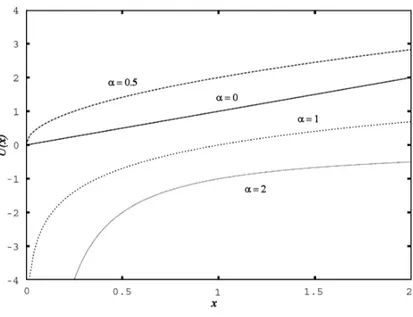
In this scenario, a fundamental choice is whether we should strive to maximize throughput fairness (i.e. achieve “max-min fairness”), maximize the total throughput (achieve the best “efficiency”), or strike a balance among the two. Typically, achieving one of these goals is directly related to the maximization of a particular “utility” metric. A widely accepted gen-eral expression for such a metric isP
jU (xj), where xj is the rate
(through-put) of flow j and U (·) is a concave function called the “utility function”. The characteristics of the utility function U (·) affect the properties of the utility metric, and consequently the particular fairness objective that is pursued. The most used class of utility functions is the one proposed in [23], which is described by the following expression:
U (x, α) = (
x1−α
(1−α), if α 6= 1
log(x), if α = 1 (2.1)
In this equation, α is a parameter that can be modified to tune the trade-off between efficiency and fairness. Some utility functions are plotted in Figure 2.1 for typical values of α. In particular, when α = 0 we should maximize U (x) = x, so the utility function leads to the extreme goal of throughput maximization, at the complete expenses of fairness. A scheduler that pursues this goal would allocate the medium to the station with the highest data rate, whereas low data-rate stations would starve. In contrast, when α → ∞, the utility function leads to extreme fairness, or max-min fairness in bandwidth. The 802.11 MAC implicitly adopts this function, achieving a long term fairness in terms of channel access probability among all the competing stations. However, as previously explained, this is may not be efficient, as the throughput of all stations tends to be aligned to that of the slowest terminal.
In most cases, including the one we are studying, the two above men-tioned behaviours are not suitable, and a different choice for α must be found. One of the results of the study presented in [24] is that a reasonable trade-off between efficiency and fairness can be obtained by setting α = 1, which corresponds to the concept of proportional fairness. In mathematical terms, this translates into maximizing P
jlog(xj), or equivalently
Q
jxj.
An interesting property of this criterion was proven in [21]. The authors demonstrate that in an infrastructured WLAN, given a fixed number of stations, the throughput of any of them is independent of the data rates used by the others if proportional fairness in bandwidth is achieved (flow isolation). In practice, proportional fairness can be realized imposing that the air-time usage shares of every station (accounting for both uplink and
2.2 The Deficit Transmission Time scheduler
Figure 2.1: Utility functions for different values of α
downlink transmissions) are equal. Proportional fairness in bandwidth is thus equivalent to max-min fairness in air-time usage.
2.2
The Deficit Transmission Time scheduler
The considerations expressed in the previous Section led us to design a scheduling algorithm whose goal is to achieve proportional fairness. The scheduler is going to be implemented at the AP and will operate according to a centralized policy, delivering fair air-time usage only to the flows ad-dressed to the associated wireless stations. As discussed at the beginning of the Chapter, this behaviour is backed by the assumption that the volume ratio of the offered traffic is biased towards the downlink direction.
2.2.1
Description of DTT
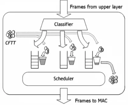
The architecture of the proposed scheduler is illustrated in Figure2.2. The whole framework is inserted above the MAC layer, which is in no way modified. A classifier splits outgoing traffic into several queues according to some predefined rule, which currently is the destination MAC address. Yet, this can be easily extended to support other rules, e.g. different user priorities, as in 802.1Q and 802.11e. A “bucket” is associated to each queue to account for the time the queued frames have spent on air during the previous transmissions. Air time is thus the “water” (or tokens) used to fill/drain the buckets.
Figure 2.2: Architecture of the DTT scheduler
At the end of every frame transmission cycle, the scheduler computes the Cumulative Frame Transmission Time (CFTT). The CFTT computation starts when the frame has reached the head of the transmission queue
2.2 The Deficit Transmission Time scheduler at MAC level and comprises the whole time spent to deliver that frame, including all retransmission attempts, backoff and idle periods. The CFTT is also produced when the retry limit is reached (i.e. in case of transmission failure). The CFTT is then used to drain the bucket associated to the destination of the transmitted frame. Next, this same value is equally divided by the number of non-empty queues and the result loads the related buckets. The bucket whose frame has just been sent, if non-empty, is included in this count. This is needed to grant all the queues the same transmission possibility. All the buckets connected to queues that have been empty for a given inactivity timeout are cleared (set to zero). This is necessary to avoid that these queues, after having been idle for a long period of time, keep a credit/debit that would reduce short-term fairness once they have some new frames to transmit (e.g. they could have enough water in the bucket to monopolize the access to medium for a while).
Once these tasks have been completed, the scheduler picks the next frame to be transmitted from the queue whose associated bucket is the fullest. If more buckets are at the same level, the scheduler chooses ran-domly among them. This frame is then passed to the MAC layer, which provides for the physical delivery. Note that all frames are stored at sched-uler level, and only one frame at a time is sent to MAC. This avoids the MAC buffer to hold any other frame but the one under delivery and allows the scheduler to make a precise computation of the CFTT and to have a tight control on the access to medium.
Let us illustrate the behaviour of the scheduler with an example (refer again to Figure 2.2). Let us consider a network with three users. The scheduler will therefore create a queue and a bucket for each associated station: left, centre, right. Let us assume that the MAC layer has just completed a transmission of a frame for the station connected to the queue on the right. Then CFTT tokens are drained from the rightmost bucket,
and, since all queues are non empty, the CFTT is divided by three and each bucket is added CFTT/3 tokens. The one on the left is now the fullest bucket, hence the scheduler will pick a frame from the left queue.
2.2.2
An insight into DTT features
To fully understand the advantages of the proposed DTT scheduler, it is necessary to develop some considerations about its main features.
The water that fills the buckets is not related to transmission times with complex formulae, but with a simple and direct one-to-one relation-ship. Thus it is exactly a transmission time, or a fraction of that, and the CFTT, in opposition to most channel models, is a deterministic measure (not an estimate, nor a prediction) of the link state. More retransmissions, possibly at lower bit rates if automatic rate fall-back (ARF) algorithms are in use, are carried out in the attempt to deliver the frame to stations whose link quality is poor. An example is reported in Figure 2.3. It refers to a successful frame transmission composed of two unsuccessful and one successful events (the third). Note that, although the DIFS and backoff periods are not strictly transmission times (as far as the radio is concerned, they are idle periods), they have been included in the evaluation since they do limit the maximum throughput.
The direct consequence of the CFTT computation and distribution method is that stations that are difficult to reach, or using low bit rates, get their buckets emptied by more water, thus having to wait longer before being chosen for the next transmission. On the contrary, easily reachable, or high data rate, terminals get their buckets lightly drained, and so they will be likely to wait for shorter intervals. Under these rules, it becomes clear that the fullest bucket is also the one whose associated queue has oc-cupied the medium for less time, and hence that should be served next to
2.2 The Deficit Transmission Time scheduler
Figure 2.3: Example of CFTT computation
achieve the long term fairness in air time usage. The name of the scheduler, Deficit Transmission Time (DTT), aims at reminding just this concept.
Some other advantages of DTT are the following. Since the scheduling metric is a simple time measure, it does not need any calibration. Then, the scheme is conservative, in the sense that the water in the buckets (that might also be negative) does not diverge, quite the reverse it always tends to zero. Finally, by introducing some weights when distributing the water, traffic and stations can be easily differentiated on the basis of various pa-rameters, such as privileged users, IP Traffic Classes (if such knowledge is available) or 802.1Q VLAN Priority tags.
Also note that only one frame at a time is sent to MAC and only after the previous frame has been transmitted (or dropped). This avoids the MAC buffer to hold any other frame but the one under delivery and therefore prevents the card from sending packets when it is not its turn. In other words, this allows the scheduler to have the tight control on the access to medium that is necessary to let it work properly.
2.2.3
Prototype implementation
The field of existence of our scheduler was not limited to theoretical de-sign and simulation tests, as it often happens for this kind of proposals, but it was extended to a prototype of a DTT-based Access Point. This allowed us to achieve two important goals. First, we had an experimental verification and measure of the effectiveness of DTT. Second and most im-portant, we realised the first working implementation of an algorithm that puts proportional fairness into practice.
2.2.3.1 Description of the prototype AP
To embed the DTT scheduler in a customisable AP, we have developed a software framework. This is realised as a set of Linux kernel modules, tightly integrated with the Host AP driver for devices based on Intersil’s Prism2.5 chipset [25]. The most relevant components of the framework are shown in Figure 2.4. This architecture is integrated in the standard protocol stack of Linux systems to allow an easy and straightforward im-plementation without the need of custom-made MAC controllers. It also allows a simple software upgrade, needing no expensive hardware replace-ment. Still, we foresee that in the future the framework could be integrated in programmable MAC controllers; as a side effect, this would additionally reduce the complexity of the scheduling architecture.
In simple Linux-based APs, the device driver encapsulates the pack-ets addressed to wireless stations into frames and passes them directly to the device, where they are queued in a hardware buffer waiting for their transmission turn. In our framework, the scheduler is inserted as a kernel module at device driver level (the Scheduler Module, which comprises all the objects of Figure 2.3). It intercepts the frames that the Device Driver
2.2 The Deficit Transmission Time scheduler
Figure 2.4: Overall architecture of the framework
is sending down to MAC and stores them internally. It dynamically cre-ates and manages as many queues and buckets as the number of registered stations. Then, after performing the operations described in Section2.2, it re-inserts a frame at a time into the transmission chain, letting the Device Driver deliver it to the MAC interface, which dispatches it over the medium according to the standard IEEE 802.11 rules. The Channel State Estima-tion Module (CSEM) is hooked to the Device Driver and is in charge of computing the CFTT and communicating it to the Scheduler Module. The Device Driver has been modified to notify the CSEM of completed frame transmissions and reached retry limits. The reception path is not touched. As stated in Section 2.2, to let the scheduler work perfectly, all frames should be stored in the Scheduler Module, keeping the hardware queue empty, and fetching a single frame from the host memory only when the
previous frame has been definitely dequeued. However, due to current hardware limitations, it is not convenient to have only one frame in the hardware buffer. The time to transfer a frame from the host memory to the device is much higher than the average idle time between two consecutive transmissions (DIFS plus backoff). This will introduce an unnecessary delay that severely reduces the maximum achievable throughput. Hence we have implemented a mechanism that manages to keep (at most) two frames in the hardware queue. One of them is the frame currently served, the other waits in the queue. This strategy obviously brings a little deviation from the ideal, which however we found to be negligible (as shown in the following). Further details can be found in [26].
The CFTT measured by CSEM is exact in the hypothesis that the AP is the sole active transmitter in the network. If another station performs a frame transmission between two transmission attempts (related to the same frame) from the AP, the CFTT will incorporate that duration too. In principle, this time should be subtracted from the CFTT. Practically, these events can be considered to occur at random intervals and consequently influence the frames of all the queues in the same way. Moreover, given the traffic unbalancing (the greater part is in the downlink direction), these events are rather limited. Therefore, to keep CSEM simple, the current implementation does not perform such an operation. We will show that this simplification does not actually affect the performance in a noticeable way.
2.2.3.2 The experimental testbed
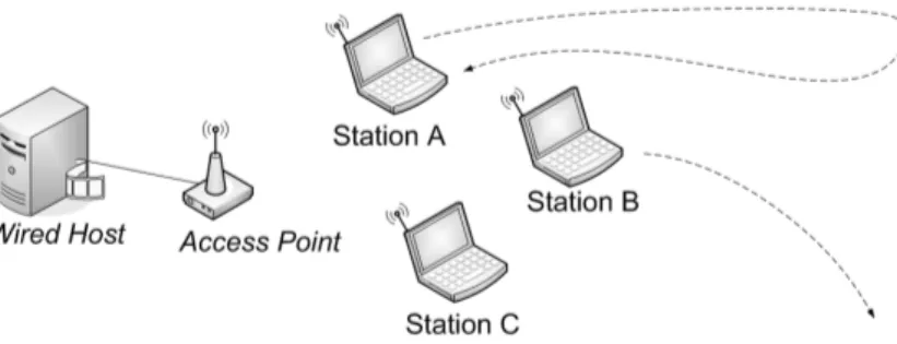
The experimental trials are performed over a testbed of one AP and a variable number of associated stations (see Figure 2.5). The scheduler has been installed on the AccessCube, which acts as the prototype AP. This is a compact hardware platform dedicated to Wireless LAN mesh routing. It is
2.2 The Deficit Transmission Time scheduler based on a 400 MHz MIPS processor running a compact Linux distribution (for technical specifications see [27]). A commercial AP, the HP Procurve 420, was used as the baseline for the FIFO discipline. The stations are simple laptop PCs. All terminals are equipped with 802.11b cards, except for the commercial AP, which is b/g capable; we have therefore configured it to support only the 802.11b standard. All cards run their vendor specific ARF algorithm. The RTS/CTS mechanism is always disabled.
The AP is connected through a wired link to a server that generates UDP and TCP traffic addressed to the mobile stations. UDP packets are created using the MGEN traffic generator [28]; TCP traffic is obtained via an FTP file transfer session. Traffic is mostly in the downlink direction, from the AP to the stations. The only exceptions are the TCP control pack-ets sent back from the stations to the server. To create various and varying channel conditions, the stations change their position, moving closer and farther from the AP, until they exit its radio coverage range, and thus are disassociated. The timeout value to force disassociation of poorly con-nected stations has been lowered, in the Host AP driver, from 300 to 30 seconds. This is an optimization that aims at quickly releasing the band-width of stations that have clearly become unreachable. It does not affect the scheduler performance, given that all its operations are carried out in a much finer time scale (one second or less). The experimental trials were run in a typical office environment.
We compared our scheduler with the simple FIFO discipline and with another solution to the performance anomaly proposed by Portoles et al. in [22]. This solution too accounts for real link conditions, but instead of scheduling frames it just tries to control the rate of the downlink flows by setting a limit that specifies, for each destination, the maximum number of packets enqueued at the AP. We will refer to this traffic shaping scheme with the acronym “PZC” from the authors’ names.
Figure 2.5: Topology of the experimental testbed 2.2.3.3 Analysis of the results
In a first try, the server generates two 5 Mbps UDP flows, with an IP packet length of 1500 bytes, addressed to two wireless stations. The system is clearly saturated, as the offered traffic is higher than what the 802.11b network can serve in ideal conditions (about 6.2 Mbps). At the begin-ning of the try both stations enjoy a very good link to the AP. After some time, station A moves away from the AP, and the quality of the link starts degrading until it is disassociated. After a while, the station gradually re-turns to its starting position, thus re-associating and improving its channel conditions. During this period, the other station (B) is constantly kept in optimal radio visibility with the AP.
Throughput values for both stations are reported in Figures2.6,2.7and
2.8. When both stations are in a good position, each one receives about 3.1 Mbps, which is half of the available throughput. So, the two flows evenly share the available bandwidth, independently of the AP scheduling policy. When station A starts moving, the differences among the different schedulers become noticeable. Measurements with the commercial AP (see Figure 2.6) clearly reveal the anomaly of the 802.11: station B, which still enjoys a good link, is dragged into bandwidth shortage when the link of station A degrades.
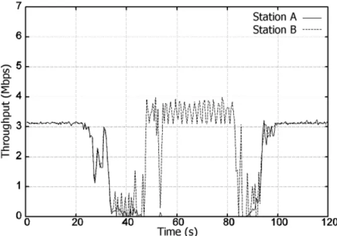
2.2 The Deficit Transmission Time scheduler The enhancements introduced by the other two schemes are likewise evident. As for the PZC scheme (see Figure 2.7), it reacts allocating more and more bandwidth to the closer station, and reducing the number of queued frames addressed to station A. However, it cannot avoid a non neg-ligible transient period. Since all the flows share the same queue, and since PZC, following to previous successful transmissions, raised the number of enqueued frames to the maximum, the AP must get through a considerable backlog of frames before handling the new situation. Additionally, as soon as a frame addressed to station A is correctly transmitted, further frames are allowed to be enqueued. Some improvement is therefore noticeable only when link quality of station A is severely reduced (after about 45 seconds), as very few (one or two) enqueued frames belong to its flow, causing just a limited impairment to the transmissions towards station B. Summarising, the maximum throughput that B can experience depends on the maximum and minimum number of frames that PZC allows to be enqueued between two transmissions to A. The higher this value, the higher the throughput, but also the higher the reaction time.
Finally, with regard to the DTT scheduler (see Figure 2.8), station B keeps receiving its data flows at roughly 3.1 Mbps almost irrespective of the other station’s position. The oscillations are due to the attempts by the AP to deliver the frames to the far terminal and to small reaction delay due to the presence of two frames in the hardware queue. Given the poor link quality, most frames addressed to A reach the retransmission limit, thus occupying the channel for the longer time possible (this includes ARF policies). As soon as station A is disassociated, station B acquires the full control of the channel. The 6 Mbps peak, present in some of the following graphs as well, is due to the packets backlogged in the AP transmission queue. In conclusion, the main response of this try is that, although the
efficiency of PZC may sporadically exceeds that of DTT, only DTT is able to completely isolate the flows and hence achieve proportional fairness.
Figure 2.6: Throughput for two flows for the standard FIFO AP
Figure 2.7: Throughput for two flows for the PZC-based AP
To increase the confidence in the achieved performance, some more tests were performed. The set of possible patterns of number of stations, move-ments, timings and traffic loads to choose from is extremely vast. As
ref-2.2 The Deficit Transmission Time scheduler
Figure 2.8: Throughput for two flows for our DTT-based AP
erence tests, we report an example of traffic asymmetry, a very simple scalability test, and a test with mixed UDP and TCP traffic. Through these tests we will show that the principle of operation of the DTT sched-uler, and the corresponding implementation in the Linux kernel, making no assumption on the number and position of the associated stations, nor on the amount and kind of traffic, is general enough to be applied to a wide variety of scenarios.
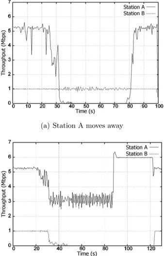
In the same context of the previous experiment, we raised the flow addressed to station A to 6 Mbps, whereas the other was lowered to just 1 Mbps. We have alternately moved both stations. The results are reported in Figure2.9 (we omit both FIFO and PZC, since we are only interested in a thorough evaluation of DTT). When both stations are in a good position, station A gets 5.2 Mbps, that is the sum of its fair share of the available capacity (3.1 Mbps) plus the 2.1 Mbps that are not used by station B. We say that DTT allows some “spare bandwidth borrowing”: if some station has no frames addressed to it, its unused air-time is distributed to the stations with non-empty queues, according to the work-conserving principle
presented in Section 2.2. The notches in the first part of the plot are due to environmental interferences. When station A moves away from the AP its throughput decreases, but the flow towards station B is unaffected, as a consequence of the flow isolation property of the DTT scheduler (see Figure
2.9(a)). On the contrary, when B moves away (see Figure2.9(b)), less and less spare air-time (i.e. bandwidth) is left for transmissions to station A. The air-time previously borrowed to A is taken back in the effort to sustain the 1 Mbps flow addressed to station B. The data rate perceived by station A drops to 3.1 Mbps, which however is nothing less than its fair air-time share. When B is finally disassociated (at around 86 s), station A can enjoy the whole channel.
The next example was used to test DTT in a scenario with more complex features than the previous cases. There are three stations (A, B, and C), at first all close to the AP. Then station A starts moving until it reaches a position in which its link becomes weaker, but is never cut (it may now represent a user standing in an unfavourable place). Later on, station B departs from the AP, and keeps on moving until it is disassociated. Towards the end of the test, B re-enters the AP coverage area. Station C always has a good connection to the AP. The behaviour of DTT is reported in Figure
2.10.
As expected, when station A starts moving, the scheduler manages to make this event unnoticeable to the other stations, which perceives no significant changes in the received throughput. A similar behaviour has been observed also when B moves. At last, when B is disassociated (at 125 s), both A and C can get more channel capacity. Station A only improves slightly, being still subject to poor channel conditions, but C is able to exploit this increase at its best, reaching 3.1 Mbps. Finally, when B re-enters the network, it can have its air-time share back, which is equally
2.2 The Deficit Transmission Time scheduler
(a) Station A moves away
(b) Station B moves away
Figure 2.9: Throughput for two asymmetrical flows under the DTT scheduler
subtracted from those of A and C. In conclusion, apart from some short-term oscillations, the three flows are still isolated.
Up to now, all the measurements have been carried out with downlink UDP traffic only. Now we introduce in the system some TCP traffic. For
Figure 2.10: Throughput for three stations with the DTT scheduler the sake of simplicity, we present two experiments in which one station is the destination of a downlink UDP flow with a data rate of 5 Mbps while the other is the endpoint of a downlink TCP session (see Figures 2.11and
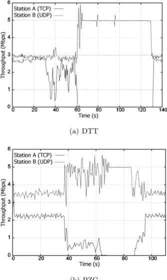
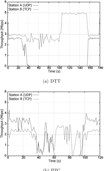
2.12). We recall that the station receiving TCP downlink traffic is requested to send (TCP) acknowledgement packets, thus subtracting a small fraction of bandwidth to the other flows. The performance of DTT is compared to PZC. The commercial AP did not yield any result, as the TCP session could hardly begin when injecting the 5 Mbps flow. When the unique AP queue gets saturated, TCP starts the congestion control procedures, thus reducing its throughput. UDP however keeps its packet rate constant and quickly monopolizes the queue, eventually causing TCP to starve.
In a first experiment the TCP station is moved away from the AP. Note that, when the PZC scheme is employed (see Figure 2.11(b)), the TCP flow is unfavoured since the beginning, and never gets close to its maximum theoretical data rate (3 Mbps), as it happens when the DTT scheduler is running. Then, when the TCP station starts moving away, DTT can grant it some degree of fairness, whereas the PZC immediately
2.2 The Deficit Transmission Time scheduler shows better regard for the closer station. Also note that, due to the congestion control mechanism of TCP, some idle periods of transmission from the queue related to the TCP station are used by the other queue, causing the small spikes visible (at around 40 s) in Figure2.11(a). When the TCP station is disassociated, both DTT and PZC let the whole bandwidth be captured by the UDP flow. When the TCP station re-associates, it acquires back its original share of air-time (and throughput).
In a second experiment the roles are inverted and the UDP sink station moves away. When DTT is running (see Figure 2.12), the TCP session is almost completely unaffected by the movement of the other station, and continues transferring bits at a data rate very close to the limit. Conversely, PZC shows once again that it is not able to refrain the two flows from influencing each other. This is a further proof of the good flow isolation properties of DTT.
2.2.4
DTT for VoIP applications
In this Section we further analyse the behaviour of DTT focusing on bidirec-tional Voice over IP (VoIP) traffic. In this context, the simple throughput, delay, and/or packet losses are not able to offer a thorough indication of the goodness of the service. Subjective factors, like human perception of voice quality, should also be taken into account. Hence we have decided to carry out a series of simulative tests within the framework defined by the E-model. This approach has already been proved to be practical by Coupechoux et al. [29], who studied the VoIP capacity of an 802.11b network operating in the DCF mode. In their work they showed that the capacity of the network is highly dependent on the position of the terminals, thus proving the effectiveness of the E-model in revealing the performance anomaly. In our study we adopt a similar approach to demonstrate that the scheduler
(a) DTT
(b) PZC
Figure 2.11: Throughput for mixed UDP and TCP traffic — TCP station moves away
we propose is successful in mitigating the already mentioned issues. The performance of DTT is compared to the basic FIFO discipline employed in commercial APs. All terminals always work with plain 802.11 cards. The maximum number of queued frames is the same for both the FIFO and the
2.2 The Deficit Transmission Time scheduler
(a) DTT
(b) PZC
Figure 2.12: Throughput for mixed UDP and TCP traffic — UDP station moves away