Universit`
a di Pisa
Facolt`
a di Scienze Matematiche Fisiche e Naturali
Corso di Laurea Specialistica in Tecnologie
Informatiche
Tesi di laurea
FACE: A software infrastructure
for controlling a robotic face
for autism therapy
Candidato
Nicole Lazzeri
Relatore
Controrelatore
Dott. Antonio Cisternino
Prof. Francesco Romani
Ing. Daniele Mazzei
Alla mia famiglia
Ringraziamenti
Ringrazio prima di tutto la mia famiglia che mi ha sempre sostenuto in tutti questi anni, aiutandomi nelle difficolt`a e permettendomi di raggiungere questo im-portante traguardo.
Ringrazio di cuore gli amici pi`u vicini, in particolare Giulia, Giulia, Vera, Angela, Giada e Pasquale, compagni di vita, di studio, di divertimenti e di risate, che mi sono stati accanto nei momenti buoni e in quelli meno buoni.
Un grazie a Gabriele, Stefano, Matteo, Alessandro e Liliana, compagni di corso e non solo.
Un sentito ringraziamento al mio relatore, Antonio Cisternino, che mi ha sup-portato durante tutto il progetto di tesi e mi ha insegnato non solo ad affrontare le difficolt`a del lavoro ma anche ad avere una visione della realt`a ”un p`o meno distorta”. Ringrazio i miei colleghi di lavoro, con cui ho collaborato in questo anno passato, sperando di poter proseguire e portare a termine ci`o che ho iniziato.
Un ringraziamento a tutti i ragazzi del CVSLab, quelli passati e quelli presenti, con l’augurio di poter continuare a condividere con loro tante fantastiche torte!
Contents
Introduction xiii
1 State of the art 1
1.1 The autism . . . 1
1.2 State of the research . . . 4
2 FACE project 13 2.1 Communication protocol . . . 15
2.2 The medical environment. . . 17
3 Implementation 21 3.1 Software development. . . 21 3.1.1 FACELibrary . . . 21 3.1.2 FACETracking . . . 29 3.1.3 FACETool . . . 33 3.1.4 FACEConfig . . . 34 3.1.5 FACERecorder . . . 37 3.1.6 FACEPlayer . . . 42 3.1.7 FACEMeshStructure . . . 46 3.1.8 FACEEditor . . . 49 4 Conclusions 67 4.1 Future works . . . 68 A SSC-32 Command Formatting 71 B Morphing algorithm 79 vii
List of Figures
1 The basic structure of OpenCV . . . xvii
2 DirectShow Filter Graph . . . xix
3 Representation of the visual and the logical trees . . . xxii
4 3D object definition . . . xxv
5 Viewing the shape from different perspective . . . xxvi
6 How the normals change the rendered surface . . . xxvi
7 Mapping between 2D Brush space and 3D surface . . . xxvii
8 2D and 3D coordinate systems. . . xxviii
9 Perspective and Orthographic projections. . . xxix
1.1 Robot Infanoid . . . 8
1.2 Robot Keepon . . . 9
1.3 Robot Kismet . . . 10
1.4 Robot Kaspar . . . 11
2.1 Robot FACE . . . 14
2.2 The six basic emotions of FACE . . . 15
2.3 Some other photos of FACE . . . 19
2.4 Some expressions of FACE . . . 20
3.1 FACE software infrastructure . . . 22
3.2 Traditional decomposition of a mobile robot control system . . . 23
3.3 Behavior-based decomposition of a mobile robot control system . . . 24
3.4 FACELibrary software structure to control FACE robot . . . 25
3.5 Haar-like features used in the classifiers . . . 30
3.6 Rejection cascade used in the Viola-Jones classifier . . . 32
3.7 FACETool interface used to control the robot . . . 34
3.8 FACETool interface used to configure new facial expressions . . . 35 ix
3.9 FACEConfig interface. . . 36
3.10 Graph filter example . . . 39
3.11 FACERecorder interface . . . 40
3.12 VMR9 Filter . . . 41
3.13 Graph plotter of the physiological signals . . . 46
3.14 The octree structure . . . 47
3.15 The octree structure of the facial mesh into the FACEEditor . . . 48
3.16 Human facial muscles . . . 52
3.17 Motor servo positions on the robotic face . . . 53
3.18 The first physics-based model . . . 54
3.19 Stress-strain relationship of facial tissue. . . 55
3.20 Elastic model of the muscle surface . . . 56
3.21 Linear Muscle Model . . . 58
3.22 Shape function with different parameter values (u = 1.0) . . . 63
3.23 Modulation of wrinkle amplitude according to skin surface . . . 64
List of Tables
3.1 Table of the acquired signals . . . 43
3.2 Table of the algorithm channels . . . 44
A.1 Command Types and Groups . . . 71
A.2 Servo Move or Group Move . . . 72
A.3 Software Position Offset . . . 73
A.4 Discrete Output . . . 74
A.5 Byte Output. . . 74
Introduction
People with autism are known to possess deficits in processing mental states and have unusual ways of learning, paying attention, and reacting to different sen-sations. FACE (Facial Automation for Conveying Emotions) is a humanoid robot able to express and convey emotions which allows autistic people to better deal with emotional and expressive information.
This thesis regards the development of a software framework to control the servo motors actuating FACE, responsible to define facial expressions of the android.
A set of tools has been developed to support psychologists in managing the robot during the therapy sessions and in analyzing the acquired data, such as physiological signals and recorded video, after the therapies.
Moreover a 3D simulator of FACE is being developed in order to allow therapists to prepare expressions and facial behaviors even off-line in a way that is compatible with the capabilities of the real robot. The algorithm used to modify the 3D facial mesh is based on a physical model which brings to more realistic expressions.
IDE and tools
Visual Studio and .NET framework
The project has been developed in Visual C# and Visual C++, which are lan-guages targeting the .NET framework, using Microsoft Visual Studio IDE, a suite of component-based development tools.
Inside the .NET framework, the Windows Presentation Foundation (WPF) is the main technology used to develop the software user interface. Previous programming models do not provide direct support for many additional features such as forms with controls, 2D/3D graphic support or video and audio streaming support. Win-dows Presentation Foundation is the next-generation graphics platform which was
purposely created to merge these unrelated programming tasks into a single unified object model.
WPF has been built under the following design principles [And07]:
DirectX. The new underlying graphics technology is no more GDI/GDI+ but Di-rectX. WPF applications use DirectX no matter what type of user interface is being created, which means that all the drawing work, complex or not, travels through the DirectX pipeline. DirectX hands off as much work as possible on the graphics processing unit (GPU) allowing benefits from hardware accelera-tion.
Integration. As mentioned above, developing a Windows application may require many technologies, ranging from GDI/GDI+ for 2D graphics, UI services (User32 or WinForms), or Direct3D or OpenGL for 3D graphics. On the contrary, WPF was designed as a single model for application development, providing seamless integration between such services within an application. Vector Graphics. To take advantage of the processing capabilities of graphics
hardware, WPF implements a vector-based composition engine. This allows graphics to scale on the basis of screen-specific resolution without loss of qual-ity, something nearly impossible with fixed-size raster graphics. WPF leverages Direct3D for vector-based rendering and will utilize the graphics processing unit (GPU) on any video card implementing DirectX 7 or later in hardware. Resolution-independent and device-independent graphics. To lay out
win-dows on the screen, Winwin-dows must make an assumption of how many dots (or pixels) per inch (dpi) a screen has. Previous programming frameworks used pixels as the unit of length. The basic unit of measurement in the WPF graph-ics system is the device independent pixel (dip), regardless of how many actual pixels that length corresponds to. WPF automatically scales each device-independent pixel to match the dpi setting of the system it render on.
Declarative Programming. WPF introduces a new XML-based language to rep-resent user interface (UI), known as XAML (eXtensible Application Markup Language). Within XAML, elements are represented as XML tags. XAML allows applications to dynamically parse and manipulate UI elements either at compile-time or at runtime, providing a flexible model for UI composition. XAML follows the code-behind model, allowing designers and developers to work in parallel and seamlessly combining their work.
Animation as a first-class programming concept. WPF includes an efficient timing system that is exposed through managed code and XAML and that is deeply integrated into the framework. WPF handles all the behind-the-scenes work, that is managing a timing system and redrawing the screen efficiently. WPF includes support to play any audio or video file supported by Windows Media Player and it allows to play more than one media file at once. It also provides the tools to integrate video content into the rest of user interface.
XAML
One of the most characteristic of WPF is the way it develops the look and feel of a Windows application and the programming logic that drives it.
Extensible Application Markup Language is a XML-based markup language used to define the appearance of an application while the managed programming language (code-behind) implements its behavior. It is possible to create UI elements in the declarative XAML markup, and then separate the UI definition from the run-time logic by using code-behind files, linked to the markup through partial class defini-tions. Unlike the most of markup languages, which are typically an interpreted lan-guage without such a direct tie to a backing type system, XAML directly represents the instantiation of objects in a specific set of backing types defined in assemblies.
This separation of appearance and behavior provides the following benefits: • It reduces costs due to the development and the maintenance because -specific
markup is not tightly coupled with appearance-specific code.
• It allows designers to implement an application’s appearance simultaneously with developers who are implementing the application’s behavior. With tra-ditional display technologies, there is no easy way to separate the graphical content from the code.
• It enables other design tools supporting XAML markup to implement and share XAML-based interface. While in Windows Forms every form created in the application is defined entirely in C# code, in WPF the appearance is completely designed by using XAML. When designing a WPF application in Visual Studio, the window it is designing is not translated into code. Instead, it is serialized into a set of XAML tags. Running the application, these tags are used to generate the objects that compose the user interface.
Another desired feature of XAML is to be fast. Though XML-based formats such as XAML are flexible and easily portable to other tools and platforms, they are not always the most efficient option. XML was designed to be logical, readable, and straightforward, not compact.
WPF addresses this shortcoming with Binary Application Markup Language (BAML), a binary representation of XAML. Compiling a WPF application in Visual Studio, all XAML files are converted into BAML, and that BAML is then embedded as a resource into the final DLL or EXE assembly. BAML is tokenized, which means lengthier bits of XAML are replaced with shorter tokens. Not only is BAML significantly smaller, but it is also optimized to be easily parsed at runtime [Mac08].
OpenCV
OpenCV is an open source computer vision library written in C and C++ which runs under Linux, Windows and Mac OS X. OpenCV was designed for computational efficiency and with a strong focus on real time applications. It was also designed to be portable making cross-platform support easier. Since the aim of the project was not addressed in the research of new computer vision algorithms, OpenCV represents a good choice providing the basic tools needed to solve computer vision problems efficiently.
One of the goals of OpenCV is to provide a simple-to-use computer vision in-frastructure that helps people build fairly sophisticated vision applications quickly. Because computer vision and machine learning often go hand-in-hand, OpenCV also contains a full, general-purpose Machine Learning Library (MLL). This sub-library focuses on statistical pattern recognition and clustering. The MLL is highly useful for the vision tasks that constitutes the core of OpenCV, but it is general enough to be applied to any machine learning problem [BK08].
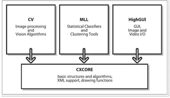
OpenCV is broadly structured into five main components, one of which is
de-clared to be obsolete. The four modules are shown in 1.
CV. The CV component contains the basic image processing, camera calibration methods, higher-level computer vision algorithms and the computational ge-ometry functions.
MLL. The MLL component is the machine learning library, which includes many statistical classifiers and clustering tools.
Fig. 1: The basic structure of OpenCV
HighGUI. The HighGUI component contains the OpenCV functions that allow to interact with the operating system, the file system, and hardware such as cameras.
The HighGUI library in OpenCV can be divided into three parts:
• The hardware part mostly concerns with the operation of cameras. High-GUI is an easy way to query a camera and to retrieve the latest image from the camera.
• The file system part concerns loading and saving images. One nice feature of the library is that it allows to read video using the same methods to read a camera abstracting away from the particular device.
• The third part of HighGUI is the window system (or GUI). The library provides some simple functions that allow to load, save and display images under the Windows environment. It also allows to register and respond to mouse and keyboard events.
CXCore. The CXCORE component contains basic data type and structure def-initions. CXCORE also contains linear algebra and statistics methods, the persistence functions, error handlers, and the graphics functions to draw on images.
CVAUX. The CVAUX component is described in OpenCV documentation as con-taining obsolete and experimental code. However, the simplest interfaces for face recognition are contained into this module.
Directshow
Microsoft DirectShow is an architecture for media streaming on the Microsoft Windows platform. DirectShow provides high-quality capture and playback of mul-timedia streams. It supports a wide variety of formats, including Advanced Systems Format (ASF), Motion Picture Experts Group (MPEG), Audio-Video Interleaved (AVI), MPEG Audio Layer-3 (MP3), and WAV sound files. It supports capture from digital and analog devices based on the Windows Driver Model (WDM) or Video for Windows. Its main design goal is to simplify the task of creating digi-tal media applications on the Windows platform, by isolating applications from the complexities of data transports, hardware differences and synchronization. At the same time, DirectShow provides an access to the underlying stream control archi-tecture for applications that require custom solutions. It is possible to create new DirectShow components to support new formats or custom effects [MSD].
DirectShow is based on the Component Object Model (COM) and it uses a modular architecture, where each stage of processing is done by a COM object called
filter. Filters are the atomic entities of DirectShow with the function to receive or
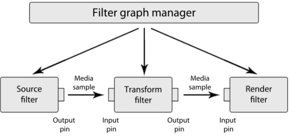
transmit a stream of data. Filter graphs are collections of filters connected together to provide specific functionalities. The connection points are also COM objects, called pins, which can either receive an input stream (input pins) or send an output stream to another filter (output pins).
Filters have three possible states: running, stopped, and paused. When a filter is running, it processes media data. When it is stopped, it stops processing data. The paused state is used to cue data before running. With very rare exceptions, state changes are coordinated throughout the entire filter graph; all the filters in the graph switch states in unison.
Filters can be grouped into several broad categories:
• A source filter introduces data into the graph. The DirectShow graph can orchestrate an audio capture from an line input, can control a digital camcorder or can capture both audio and video from a live camera, such as a webcam.
Fig. 2: DirectShow Filter Graph
It is possible to open a file and treat it as if it were a live source. Each source filter handles a different type of data source.
• A transform filter takes an input stream, processes the data, and creates an output stream. A transform filter can parse a stream of data, add a text overlay on a video sequence, desaturate a video, change the resolution video, or add an echo effect to an audio stream. These transform filters can be connected, one after another, until the desired effect is achieved. Examples of transform filters are:
– encoder and decoder filters transform the data flow using a set of sup-ported codec;
– splitter filters split an input stream into two or more outputs, typically parsing the input stream along the way. For example, the AVI Splitter parses a byte stream into separate video and audio streams;
– mux filters take multiple audio/video inputs and combine them into a single stream. For example, the AVI Mux performs the inverse operation of the AVI Splitter. It takes audio and video streams and produces an AVI-formatted byte stream.
• Renderer filters sit at the end of the chain. They receive data and render the media stream by sending it to the display or to the speakers, or by writing it into a file into the disk or into a device such as a digital camcorder. For example, a video renderer draws video frames on the display; an audio renderer sends audio data to the sound card; and a file-writer filter writes data into a
file. DirectShow renderer filters use DirectDraw and DirectSound, supporting technologies that allow DirectShow to efficiently pass its renderer filter streams along to graphic and sound cards. A filter graph can have multiple renderer filters. It is possible to put a video stream through a tee, sending half of it to a renderer filter that writes it to a file, and sending the other half to another renderer filter that displays it.
All DirectShow filters have some basic properties that define the essence of their modularity. Each filter can establish connections with other filters and can negotiate the type of connections it is willing to accept from other filters. For example, a filter designed to process MP3 audio does not have to accept a connection from a filter that produces AVI video. Each filter can receive some basic messages, such as run, stop, and pause, that control the execution of the filter graph. As long as the filter exposes these properties through COM, DirectShow will treat it as a valid element in a filter graph.
The modularity of DirectShow extends to the filter graph. Just as the internals of a filter can be hidden from the programmer, the internals of a filter graph can be hidden from view. When the filter graph is treated as a module, it takes the change of connecting filters together in a meaningful way. It is possible to create a complete, complex filter graph by using a source filter and a renderer filter. These filters are then connected with a technique known as Intelligent Connect. Intelligent Connect examines the filters in the filter graph, determines the right way to connect them, adds any necessary conversion filters, and makes the connections in a way that is transparent to the programmer [MSD].
Prerequisites
WPF
It is helpful to examine some of the main concepts that characterize WPF so to better understand the structure of applications.
Logical and Visual Tree
In WPF, user interfaces are constructed from a tree of objects known as a logical
hierarchical nature but a logical tree exists even for WPF user interfaces that are not created by using XAML.
The logical tree concept is important because just about every aspect of WPF, such as properties, events, resources, and so on, has behavior tied to the logical tree. For example, property values are sometimes propagated down the tree automatically, and raised events can travel up or down the tree.
The logical tree is responsible for: • inheriting DependencyProperty values • resolving DynamicResources references • looking up element names for Bindings • forwarding RoutedEvents.
The logical tree exposed by WPF is a simplification of what is actually going on when the elements are rendered. The entire tree of elements actually being rendered is called the visual tree. Not all logical tree nodes appear in the visual
tree; only the elements that derive from System.Windows.Media.Visual or Sys-tem.Windows.Media.Visual3D are included.
The visual tree is responsible for: • rendering visual elements • propagating element opacity
• propagating Layout and RenderTransforms • propagating the IsEnabled property
• doing Hit-Testing
• using RelativeSource (FindAncestor) property.
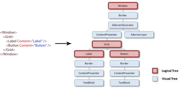
It is possible to imagine the visual tree as an expansion of the logical tree, like a scene graph, containing all the rendering information needed to compose the output and to show it to the display device, like in Fig. 3.
Because both trees enable users to peer inside the deep composition of WPF elements, their structure can be very complex. It is easy to traverse both the logi-cal and visual trees using the symmetrilogi-cal System.Windows.Logilogi-calTreeHelper and
Fig. 3: A snippet of code and the corresponding representation of the visual and the logical trees
Dependency properties
WPF introduces a new type of property called dependency property that is used throughout the platform to enable styling, automatic data binding, animation, and more.
Before looking at the new paradigm for properties, it is useful to mention some important things about the standard .NET properties:
• a property is mostly used to expose a private field in the class, in which case the field is called backing field
• a property is a functional member of the class, which means it executes code. – assigning a value to a property means that the value is passed to the set
accessor, which usually assigns it to the backing field.
– reading from a property means that the get accessor usually just returns the value of the backing field.
The get and set accessors are not constrained to set and return the backing field. They execute the code the programmer chooses to put in them. The only constraints are that the get accessor must return a value of the correct type.
• the value of a dependency property is not stored in a simple field, but it is determined as needed.
• the value of a dependency property at any given time can depend on many factors. Because some of these factors can be changing, the value of a depen-dency property can change, even though the code has not assigned a new value to it
• there is an integrated set of services, called the WPF property system, whose charge is to keep track of all the factors and determine the values of these properties on-demand.
• the syntax reserved for dependency properties is the same syntax used to express and manipulate ”classic” properties. in your code or markup is the same as that for using properties that are not dependency properties.
Dependency properties in the WPF libraries are always wrapped into ordinary .NET property procedures but they are not normal properties. The motivation for adding the features listed above is to expose efficiently rich functionalities directly into declarative markup. The extensive use of properties plays a key role in WPF declarative-friendly design. Properties can be easily set in XAML without any pro-cedural code but, without the extra concept of dependency properties, it would be hard for the simple action of setting properties to get the desired results without the need to write additional code.
WPF, XAML and 3D
Developers have used DirectX and OpenGL to build three-dimensional inter-faces for many years with all the difficulties of a complex programming model and substantial video card requirements.
WPF introduces a new expansive 3D model which allows the users to build up complex 3D scenes out of simple markup. WPF libraries for 3D programming are designed to be a clear, consistent extension of the WPF model and to give the pro-grammers the ability to integrate 3D scenes into their client Windows applications. Helper classes provide all that it is needed to manage the editor aims, from hit-testing to mouse-based events, and other 3D fundamental operations. Almost any computer can display the 3D content, thanks to WPF ability to fall back on software rendering when video card support is lacking. Furthermore it is possible to rely on
a third-party tool to create 3D objects, to export them to XAML, and then to add them to WPF applications.
Traditionally in 3D computer graphics, the surfaces of 3D figures are defined by a polygonal mesh, which is a collection of 3D points arranged to form polygons. For figures with flat surfaces, generally only few polygons are needed, but curved surfaces require many polygons to approximate the curvature of the figure.
WPF 3D uses the simplest form of polygon to create a mesh, the triangle. Set of any three non-coincident and non-collinear points defines a triangle and, in effect, a plane, so that triangles are always flat. A larger set of points can be used to define more accurately the mesh describing a surface.
In WPF, a 3D scene includes the following elements:
Viewport3D. The control that hosts the 3D content in a way that bridges the 2D and the 3D world.
3D models. A 3D model defines an object in the scene. It has a Geometry property which represents the mesh and a Material property that defines the type of surface.
Camera. Every 3D scene has exactly one camera. The camera defines the
Posi-tion, the LookDirection and the UpDirection of the viewer. WPF supports orthographical and perspective cameras.
Lights. Without any light the 3D scene is completely dark. It is necessary to place at least one light in the scene to illuminate the models.
Viewport3D
Viewport3D belongs to the System.Windows.Controls namespace and it provides
a container to host and render the 3D scene. Viewport3D derives from
Frame-workElement class, which means that it can be a part of a larger layout of elements,
and it can receive mouse, keyboard, and stylus input events. The property Children of Viewport3D is an instance of Visual3DCollection, that is a collection of Visual3D objects. Visual3D is an abstract class and has only one descendant, named
Mod-elVisual3D, which defines the type of the items in the scene. The ModelVisual3D’s Content property should contain the visual objects. Typically, the Content
prop-erty holds either a single GeometryModel3D object that defines the entire scene or a Model3DGroup object that holds a collection of GeometryModel3D objects.
Fig. 4: 3D object definition
Model3D
A GeometryModel3D is a Model3D that combines two properties, Geometry and
Material.
Geometry property defines the shape of visible objects using a MeshGeome-try3D object, the concrete instance of a GeomeMeshGeome-try3D. WPF 3D model exposes the MeshGeometry3D class which defines the geometry of a figure. Four properties are
important to compose a mesh:
• Mesh Positions. A mesh position is the location of a single point on a surface represented by a 3D coordinate point (x, y, z). WPF 3D defines a structure named Point3D that stores one of these coordinate points. This property contains a collection of all the points that define the mesh. Depending on its geometry, the mesh might be composed of many triangles, some of which share the same vertices, which means that one point will become the vertex of several triangles. It is possible to define the same shared vertex multiple times to better control how separated triangles are shaded with the Normal property.
• Triangle indices. A triangle index is a mesh position which defines one of the three points of a triangle in the mesh. Each entry in this collection contains three points referring the Positions collection which represent a single triangle. In WPF, the order in which the triangle indices are added is important because it establishes how the figure appears. Although a triangle is flat, it exists in 3D space and it has a front and a back. When the triangle is viewed from the front, the three indices in the TriangleIndices collection must refer to the vertices of the triangle in a counter-clockwise direction.
• Triangle normals. A normal is a vector that is perpendicular to a surface in a particular point. While the order of triangle indices determines which side
Fig. 5: Viewing the shape from different perspective
of the triangle is visible, the normals of the vertices tell the system how the surface should be lit by a light source. When the normals for each vertex in a triangle are parallel the rendered surface appears flat. If the normals point in different directions, the shading is smoothly interpolated across the face of the triangle.
Fig. 6: How the normals change the rendered surface
• Texture coordinates. Each entry in the TextureCoordinates collection is a 2D point in Brush space which is specified as a value between 0 and 1. The triangles in Brush space provide the colors for the materials when the surface is rendered. These points determine how a texture is drawn to vertices of the mesh.
Fig. 7: Mapping between 2D Brush space and 3D surface
The Material property must be defined to view the object because of a
Geom-etry3D by itself is a 3D surface with no appearance. WPF provides three kinds of
materials:
• DiffuseMaterial. Creates a flat, matte surface. It diffuses light evenly in all directions. The brightness of a diffuse material depends on the angle at which light hits it, but the brightness does not depend on the angle at which the user looks at it.
• SpecularMaterial. Creates a glossy, highlighted look (metal or glass). It reflects light back directly, like a mirror. A specular material is somewhat shiny. In that case, the apparent brightness of an object depends on how much closely the angle between the user, the object, and the light sources matches the object’s mirror angle. The mirror angle is the angle at which most of the light would bounce off the object if it were perfectly shiny.
• EmissiveMaterial. Creates a glowing look. It generates its own light, although this light does not reflect off other objects in the scene. An emissive material glows but only on itself. In other words, it makes its own object brighter, but it does not contribute to the brightness of other nearby objects as a light would do.
Camera
By placing a virtual Camera into the 3D scene the programmer can control what will be visible in the Viewport3D. This is done by positioning and orienting
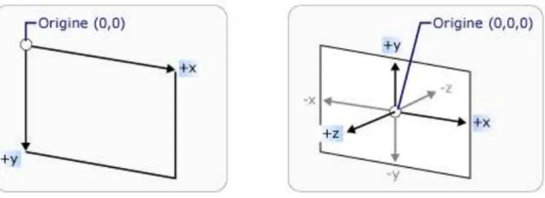
the Camera in the world coordinate system, called world space. The 3D coordinate system used in WPF assumes the origin to be at the center of space as opposed to the top-left corner in 2D system.
Fig. 8: 2D and 3D coordinate systems
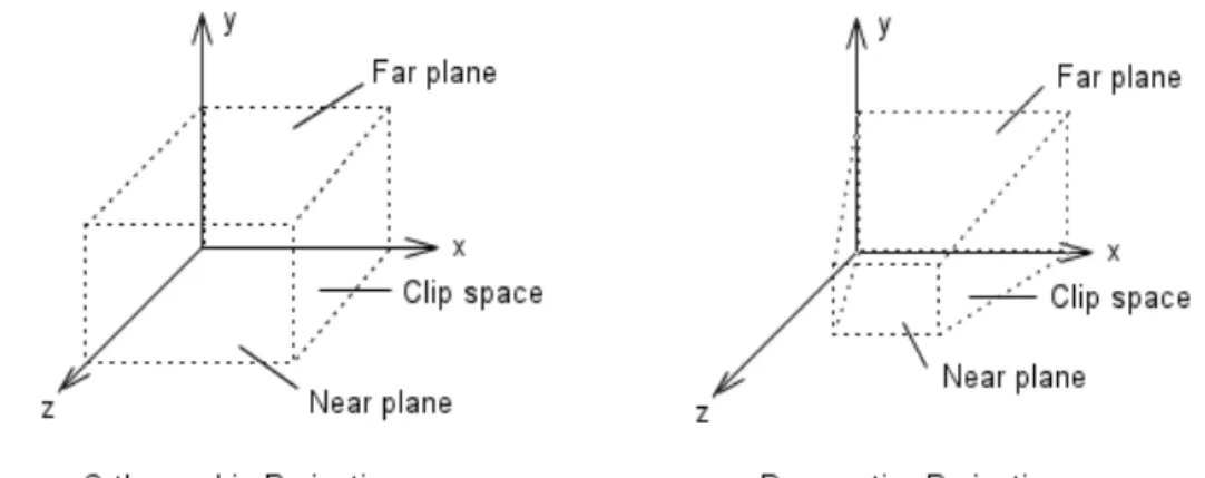
The camera determines how a 3D scene is projected onto the 2D surface of a Viewport. WPF has three types of cameras: Perspective, Orthographic and Matrix. The Perspective camera, in which parallel lines seem to merge toward a vanishing point, foreshortens items so objects farther from the Camera appear smaller than the closer ones. Since this is similar to the way humans see things in real life, the result is more realistic. The Orthographic camera, in which the parallel lines remain parallel, puts everything in the right place preserving the exact scale, but does not shrink things into the distance and objects appear at the same size, regardless of their distance from the Camera. While this is less realistic, this camera can be useful to get measurements of 3D architectural models. Finally, the Matrix camera allows the user to specify a custom projection matrix that is used to transform the 3D scene to 2D view. It can be useful, for example, to port code from other frameworks (such as Direct3D) that use this type of camera.
The following properties are used to specify the location and the orientation of a camera:
• Position. The point in the 3D coordinate space where the camera is located. • LookDirection. the direction in which the camera should be pointed relative
to its current position.
• UpDirection. The camera’s roll or tilt.
Another camera property is the FieldOfView, which controls how much of the scene it is possible to see at once. FieldOfView is comparable to a zoom lens on a
camera. The more the FieldOfView is decreased, the smaller portion of the scene is viewed (which is then enlarged to fit the Viewport3D). The more the FieldOfView increases, the greater the portion of the scene is viewed.
The NearPlaneDistance and the FarPlaneDistance properties set the blind spots of the camera. Objects closer than the NearPlaneDistance and objects farther than the FarPlaneDistance will not appear at all.
Fig. 9: Perspective and Orthographic projections
Lights
The color seen in a scene depends both on the materials used and on the lights coming from the objects in the scene. WPF provides several kinds of lights producing different effects:
• Ambient Light. It fills the scene with parallel rays of light traveling in the direction the user specifies. This is the light that comes from all directions and hits every surface.
• Directional Light. It fills the scene with scattered light. This light shines in a particular direction as if the light was infinitely far away.
• Point Light. It radiates light in all the directions, starting from at a single point in space.
• Spot Light. It radiates light outward in a cone, starting from a single point. Objects directly in front of the cone receive the full light, while objects farther to the sides receiving less.
Chapters organization
The thesis is organized as follow:
Chapter 1, State of the art. This chapter explains what is the autism and what kind of deficits it can give. It describes the state of the art in the robotic research focused to provide new tools to help autistic people to get a ”normal” life as much as possible.
Chapter 2, FACE project. This chapter introduces the FACE project. In partic-ular, it describes the technical characteristics of the robot and the environment for the medical sessions.
Chapter 3, Implementation. This chapter illustrates the thesis project whose main target is to develop a software infrastructure to control the robot and a set of tools to help the psychologists to analyze the acquired data during the therapies.
Chapter 4, Conclusions and future works. It summarizes the guidelines of the thesis explaining the reasons that led up to the its development. Finally, it exposes some future works regarding the FACE project.
Chapter 1
State of the art
1.1
The autism
The autism is a complex developmental disability that typically appears during the first three years of life. Autism affects the normal development of the brain in the areas of social interaction, communication skills and cognitive function. Individuals with autism might have unusual ways of learning, of paying attention, and of reacting to different sensations.
The autism is part of a group of developmental disorders known as the Autism
Spectrum Disorders (ASD). This group also includes Asperger disorder and pervasive
developmental disorder-not otherwise specified (PDD-NOS). Persons with Asperger disorder or PDD-NOS have fewer diagnostic symptoms of ASDs compared with autism, and the symptoms often are indicative of more mild impairment [FAIS03].
Although symptoms belonging to the Autistic Spectrum Disorders (ASDs) were firstly described 50 years ago, improved understanding of this complex spectrum of disorders has emerged over the past two decades, and, despite recent intense focus, it continues to be an art and a science that is quickly evolving [PIS+08]. The
complex nature of these disorders, the current lack of consistent and reliable genetic or biologic diagnostic markers, and the changes in how these conditions are defined and identified, make evaluating ASD prevalence over time a challenge.
Although everyone with an ASD has significant challenges in certain areas of his or her life, some might be gifted in other areas. Also, not everyone with an ASD has the same challenges. Some individuals might have relatively good verbal skills, but have difficulty interacting with other people. Others might not be able to talk or have very little ability or interest in communicating or interacting with
2 CHAPTER 1. STATE OF THE ART
others. People with ASDs often do not take part in pretend play, have a hard time starting social interactions, and engage in unusual or repetitive behaviors (e.g., flapping hands, making unusual noises, rocking from side to side, or toe walking).
There is no medical test for ASDs. Typically, a diagnosis is made after an evaluation by a qualified professional. Such an evaluation might include clinical ob-servations, parent interviews, developmental histories, psychological testing, speech and language assessments, and eventually the use of one or more autism diagnostic tests.
Recent publications reported that early in the new millennium the best estimate of current prevalence of ASDs in Europe and North America is approximately 6 per 1,000. Regardless of the study, of the year conducted, or of the reported rate of prevalence, more boys than girls are consistently found to be affected with ASDs, with male to-female ratios ranging from 2:1 to 6.5:1. The male-to-female ratio is even higher for high-functioning autism and ASD, ranging from 6:1 to 15:1.63 [MJtCoCWD07].
It is not exactly know what causes the autism. Its prevalence is not affected by race, region, or socio-economic status and it does not affect life expectancy. Currently there is no cure for autism, so an autistic child will grow up to become an autistic adult. However, because of the nature of the disorder, if it is diagnosed within the first three years of the child’s life, a special education program can be implemented which will maximize the chance of the child to grow up and live a life in a way that is as self-sufficient as possible. If diagnosis occurs early enough, the resulting treatment will be more effective, and many children have been able to achieve relatively ’normal’ lives as a result [KI00].
For the NAS, National Autistic Society, the UK’s foremost charity for people with autistic spectrum disorders, the deficits are classified in three main areas:
• Social interaction: it is possible to notice that the autistic children do not seek interaction in the way that ’normal’ children do. Autistic children often do not acknowledge the presence of another person in their environment, even when that person is actively trying to engage the child’s attention. This may be due to a number of reasons: autistic children require extreme stability and enforced routine while people can show very complex behavior which is very difficult to predict for the autistic person. Also, a person is able to communicate in a number of different ways, not only with the actual words but also with the tone of voice, as well as body posture and body language. Autistic children have
1.1. THE AUTISM 3
great difficulties to filter their sensory input because they must concentrate on one aspect at time and often they focus all of their attention on small details. The use of a robot is perceived as a toy by the autistic children so it becomes a facilitator for interaction. A robot is carefully controlled and is predictable, and at the same time it allows the child to interact with it on his own terms. The children are not frightened by the robotic agent and they enjoy the chance to interact through the medium of play.
• Social communication: another symptom that can be noticed in autistic chil-dren is that they appear extremely quiet and reserved. Autistic chilchil-dren often have difficulty in speaking and they are not capable to interpret the meaning of various gestures and facial expressions. Abstract meanings and concepts are difficult to understand so autistic children are sometimes able to communicate using picture representations. A fundamental part of communication is the concept of turn-taking that can be implemented through simple games using voice and movement abilities of the robot. Although the robotic agent is not perceived as another person, certain intelligence is attributed to it, bridging the gap between the communication of normal people often too rich, and the extremely limited ability of simple toys to engage and inform.
• Imagination: the third of the impairments observed is a deficiency in the area of imagination and imaginative play. Autistic children show extremely limited ability to project outside of their directly sensed environment. They are unable to make the ’leaps of faith’ required to project unreal situations and attributes on to real events and objects. Sarcasm, irony and lying are general difficult or impossible to understand for people with autism. They take the literal meaning of language and do not grasp the underlying meaning of the phrase. Without the ability to generalize beyond what we can directly perceive, people become two dimensional objects without intentions, knowledge and an ’inner life’ which may be different from ours. One of the consequences is that autistic children have a strong preference for repetitive action, unwilling to explore and break the routine and stability, and are unable to see the possibilities beyond the current action. A robot will be familiar in its behavior, providing the stability and the security which is needed, but it will also be able to vary from the established routine by small amounts and persuade the child to try new ideas within an established framework [KI00].
4 CHAPTER 1. STATE OF THE ART
All those considerations indicate that robotic technology may be used to help subjects with ASDs understanding and teaching face recognition and emotion pro-cessing could be of an high clinical significance. A robotic agent will be able to contribute to the rehabilitation process of autistic children and to provide an addi-tional method for the rehabilitation. The state of the art in the robot-based therapy has shown the usefulness of the interaction of a robot with autistic patients within a highly structured environment where it is possible to recreate social and emotive scenarios that can be used to stimulate and anticipate the actions of a subject. In addition, while the stress of learning with a teacher can often be excessive, interac-tion with a robot, which young patients often associate with media and/or cinema characters, can reduce the emotional and social pressure of the situation, allowing
the child to learn from the environment at his or her own speed [PIS+08]. In this
perspective, a robot is able to become a teaching aid, helping the children to learn tasks and actions which can be built on later by teachers and parents [KI00].
Robotic artifacts are used to act as social mediators in order to increase the
social interaction skills of children with ASDs [PIS+08]. A robot can increase the
attention span of the child, by simply being engaging and less threatening than a human. Furthermore the robot is able to mimic the child and vice versa, to provide either a stimulus or reward for an action [KI00].
1.2
State of the research
For over thirty years researchers have been investigating the usage of robots in education. The use of a robotic platform is an attempt to bridge the gap between the stable, predictable and safe environment of a simple toy, and the potentially unpredictable world of human contact and learning. People’s social behavior can be very subtle and widely unpredictable, on the other hand a robot can be used to create a simplified environment and, at the same time, to gradually increase the complexity of interaction, according to the individual child’s abilities [AuR].
The researchers’s attention is often more focused on the robotic platform rather than on the software structure controlling the robots therefore it will be presented a vision more addressed on the robotic research used in therapies with autistic children rather than on the development of the software infrastructures.
The use of robot technology to help autistic subjects began in 1976 with the work of Sylvia Weir and Ricky Emanuel. They used a mobile turtle-like robot, LOGO,
1.2. STATE OF THE RESEARCH 5
able to interact with a patient within a highly structured environment [WE76]. The potential use of computers and virtual environment technology in autism therapy is increasingly studied. People with autism often interact very naturally with computer technology and use it in an exploratory and creative manner. A humanoid robot, i.e. a robot that can match at least to some basic behaviors of human beings, arm, head and eye movements, is an interesting tool to study robot-human interaction, and in particular social interaction dynamics. Generally, computer technology in education and therapy has the big advantage to give the control to the child, under the eventual guidance of and with the feedback of the teacher [DB02].
More recently Fran¸cois Michaud and his research team at the University of Sher-brook investigated the use of mobile robot as a treatment tool. They tested several robots, different in shape, color and behavior, in order to study the characteristic that mainly capture the attention of people with autism. They obtained important insights for the comprehension of the human-robot interaction in autism sustaining the robot hypothesis as useful. People with autism focus their attention on singles details, but the interaction with a robot may allow an autistic subject to concentrate herself/himself on the limited number of communication modalities of the robot. In particular, they found that children paired with the robot mediator demonstrated increased shared attention (visual contact, physical proximity) and imitated facial expressions (smile) more than the children paired with a human mediator. [FAIS03] A more structured approach in exploiting autonomous robots is AURORA (AU-tonomous RObotic platform as a Remedial tool for children with Autism) [AuR]. AURORA represents the first systematic study on robot therapy in autism. People with autism are invited to interact with the robots and the environment through co-ordinated and synchronized social actions. Previous research in the Aurora project illustrated the ability of a mobile robot to provide a focus of attention, and shared attention, in trials with pairs of children with autism.
One of the robots used in this project is Robota, a 50cm tall, humanoid robotic doll, weighing 500 grams. Robota is the name of a series of doll-shaped mini-humanoid robots developed in a project headed by Aude Billard. The first prototype of Robota is made out of LEGO parts for the body and of plastic components of a commercial doll for the arms and the head. There are three LEGO motors inserted in the body to drive the arms and the head. The robot is provided with five touch sensors, placed under the feet, inside the hands and the mouth, a tilt sensor that measures the vertical inclination of the body and four infra-red (IR) detectors. Each
6 CHAPTER 1. STATE OF THE ART
infra-red detector consists of an emitter and a receptor. The simple communication system consists of a keyboard and a loudspeaker. The robot controller is made of a micro-controller with 512k byte EPROM space and 128k byte Static RAM. The CPU is a Phillips 93C100 series 68000 compatible running at 30 MHz. All electrical circuits are external to the robot. Sensors and motors are connected via external wires [DB02].
The second prototype, Robota II, has the same abilities of the first prototype, but each module is much more sophisticated. In addition to moving the arms and the head, the second Robota can walk forwards and backwards by making small saccadic stepping. The body of the robot is that of a commercial doll and it contains the electronic boards (PIC16F870, 4 MHz and 16F84, 16 MHz) and the motors that drive the arms, legs and head giving 1 DOF (degree-of-freedom) to each. It has numerous sensors (switches on the hands, head, mouth, leg, inclination sensor, IR-proximity sensors, pyroelectric sensor for detecting human movements). Similarly to the first prototype, the second robot can be connected to external devices: a pair of glasses and a pair of hand sensors for the imitation set-up and a keyboard. The keyboard contains a set of eight keys, a loudspeaker, a 6-positions joystick. The whole is controlled by a chip (PIC). The keyboard is preprogrammed to play one note of the musical scale for each of the eight keys. That is, the 8-keys of the keyboard are an electronic xylophone. The robot has also a microphone inside the body which allows it to repeat the sounds (with its own voice). The joystick allows one to direct the robot arms and the head movements (lifting up and down the arm and shaking the head on the sides). This provides an additional mean, on top of the infra-red mirroring set-up, to orchestrate the robot.
Robota II is interfaced to a PC or a PocketPC through an RS232 serial connection
to use speech synthesis (ELAN), speech processing (Conversay, IBM Viavoice) and to process video data from a Quick-Cam camera (CMOS, 640 Œ 480, 30 fr/s). The Quickcam camera allows the robot to detect human presence, using a simple color and motion processing algorithm. Using its motion tracking system, Robota II can copy upward movements of the user’s arms, and sideways movements of the user’s head when the user sits very still and close to the robot, looking straight at it, engaging in turn-taking and in imitation games with the robot.
Speech recognition is provided by a commercial speech processing software to extract words from the sentences and assign them a meaning in terms of the robot’s perceptions. The learning algorithm is provided by an artificial neural network,
1.2. STATE OF THE RESEARCH 7
called DRAMA (Dynamic Recurrent Associative Memory Architecture). Once the language has been learned, the robot can talk with the user through the PC loud-speaker. The DRAMA learning algorithm runs also on the robot and allows the robot to learn melodies (as played by the user on the keyboard) and to learn dance patterns for each melody (by associating sequences of movements with sequences of notes). In addition, the robot spontaneously can put on music files and start dancing (i.e. moving backwards-forwards and making head and arm movements). It can also play baby-like sounds, such as laughing and crying, which depend on its mood.
The code is written in C and C + + and runs both under Linux and Windows 95/98. It was tested on a HP4100 laptop, Pentium II, 266MHz, 96M and was shown to run on real time [Bil03].
From the epigenetic robotics point of view, by observing human cognitive de-velopment, especially of infants and children, and by modeling their development in robotic systems, Hideki Kozima at the National Institute of Information and Communications Technology (NICT) of Japan developed two robots, Infanoid and
Keepon.
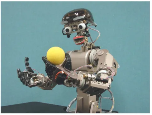
Infanoid is an upper-torso humanoid robot which is as big as a 3- to 4-year-old
human child. It has 29 actuators (mostly DC motors with encoders and torque sensing devices) and some sensors arranged in the relatively small body. It has two hands capable of pointing, grasping, and to emulate a variety of hand gestures; it also has lips and eyebrows to produce various facial expressions, like surprise and anger. By changing the inclination of and the gap between the lips, it expresses a variety of emotional states.
The head of Infanoid has two eyes, each of which contains two different color CCD cameras. The video images taken by the cameras are fed into a cluster of PCs for real-time detection of human faces (by skin-color filtering and template matching) and of physical objects such as toys (by color/motion segmentation). The distance of the face and objects can also be computed from the disparity between the left and right images.
By using the microphones placed inside the ears, Infanoid hears human voices and analyzes the sound into a sequence of phonemes. By feeding the phoneme string with the extracted pattern of fundamental frequency, Infanoid performs vocal imitations while sharing attention with the interactant. It also recognizes any change in the fundamental frequency to extract an emotional contour from human speech.
8 CHAPTER 1. STATE OF THE ART
Fig. 1.1: Robot Infanoid
The robot can run in Automatic Mode, in which it alternates between eye-contact and joint attention with pointing. If necessary, a remote operator can make adjustments to the robot’s attention (e.g. direction of the gaze and body posture) [KNY05].
Keepon is a small (12cm in height, 8cm in diameter), soft (made of silicone
rubber), creature-like robot used psychological experiments with younger children. It can perform only two kinds of motion: (1) expressing its attention by orienting its face toward a certain target in the environment, and (2) expressing its emotional states, such as pleasure and excitement, by rocking its body from left to right and by bobbing up and down. Keepon is connected by wireless links to a remote PC, from which a human operator or a computer program controls the motion. Although its appearance is quite simple, Keepon has two color CCD cameras and one microphone on the nose tip which provides almost the same audio-visual capabilities as those of
Infanoid [KNY05].
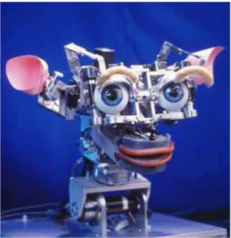
For a robot, the ability to convey intentionality through infant-like responses could be very useful to establish natural, intuitive, flexible, and robust social ex-changes with a human. Kismet, developed by Cynthia Breazeal at the Robotic Life Group of MIT Media Lab, responds to this question, performing a variety of re-sponses by means of several natural social cues (including gaze direction, posture,
1.2. STATE OF THE RESEARCH 9
Fig. 1.2: Robot Keepon and facial displays).
Kismet is a humanoid face that can generate expressive social interactions with
human and can show expressions analogous to happiness, sadness, surprise, boredom, anger, calm, displeasure, fear, and interest. It has been designed to have an infant-like appearance of a robotic cartoon character. The overall cartoon-infant-like appearance of the robot took advantage of people’s liking and familiarity with cartoon characters and this design is based on the assumption that people are eager to interact with the robot in the role of a caretaker.
Kismet has fifteen degrees of freedom in facial features, including eyebrows, ears,
eyelids, lips, and a mouth. The platform has also four degrees of freedom in the vision system; each eye has an independent vertical axis of rotation (pan), the eyes share a joint horizontal axis of rotation (tilt), and a one degree of freedom neck (pan). Each eyeball has an embedded color CCD camera with a 5.6 mm focal length. Kismet is attached to a parallel network of eight 50MHz digital signal processors (Texas Instruments TMS320C40) which handle image processing and two Motorola 68332-based micro-controllers which process the motivational system [BFS98].
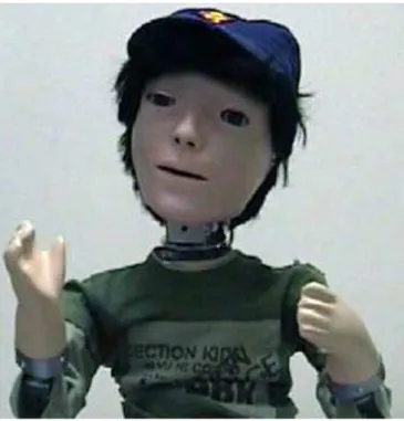
More recently, it has been explored the possibility to use a more ”socially ca-pable” robotic platform to interact with autistic children. KASPAR (Kinesics and
10 CHAPTER 1. STATE OF THE ART
Fig. 1.3: Robot Kismet
Synchronization in Personal Assistant Robotics) is a project focused on what it is called a minimally expressive face to concentrate on a few salient behaviors, ges-tures and facial expressions in order to run experiments that systematically study the influence of each of these cues on the interaction with people.
KASPAR is a child-sized robot that uses mainly expressions and gestures to
communicate with a human interaction partner. The robot has a static body (torso, legs and hands do not move and are taken from a child-sized commercially available mannequin doll) with an 8 DOF head and two 3 DOF arms. Important features of KASPAR head are minimal design, the inclusion of eyelids, and aesthetic consistency of the face.
The overall design of KASPAR’s head and face aims to approximate some impor-tant features of the appearance and movements of a human without trying to create an ultra-realistic appearance, i.e. not trying to imitate every detail of a human face. The robot can be used in two modes: remotely controlled as well as in au-tonomous operation. Unskilled operators can easily run and develop programs for the robot using the novel user-friendly KWOZ (KASPAR Wizard of OZ) Graphic User Interface (GUI) software which runs on any Windows or Linux PC. This in-terface has been used in human-robot interaction scenarios when an experimenter (usually hidden to the participants) remotely controlled the robot from a laptop. This type of control is different from the remote control device that was specifically
1.2. STATE OF THE RESEARCH 11
Fig. 1.4: Robot Kaspar
implemented to introduce collaborative games [DNW+
09].
In a variety of projects KASPAR operates autonomously. An Applications Pro-gramming Interface (API) allows the programmers to develop custom programs and exploit the open source robot software produced under the YARP (Yet Another Robot Program) initiative.
Chapter 2
FACE project
The acronym F.A.C.E. means Facial Automation for Conveying Emotions and it is a project developed at the Interdepartmental Research Center ”E. Piaggio” of the University of Pisa in collaboration with IRCCS Stella Maris Institute of Calambrone (Pisa).
F.A.C.E. is a human android used in a structured therapeutic environment in which the autistic subject’s behaviors and responses are monitored using an array of sensors and then processed and fed back to the android to modulate and modify its expressions. The integrated sensing, monitoring, processing and emotionally responsive android-based therapeutic platform is termed FACET (FACE Therapy). FACET allows the emotive status of the subject to be assessed during therapy.
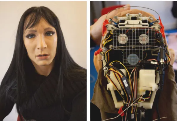
FACE consists of a passive articulated body equipped with a believable facial display system based on biomimetic engineering principles. The latest prototype of the FACE head is fabricated by means of life-casting techniques and aesthetically represents a copy of the head of a subject, both in shape and texture.
The head of the robot consists of an artificial skull covered by a special skin made
of FrubberTM, a particular material developed by Hanson Robotics. FrubberTM, a
patented silicone elastomer whose mechanical properties allow the complex facial movements, is a foamed platinum-based elastomer that contains up to 70% air by volume. The control of the size and distribution of the open and closed air cells in
the FrubberTM skin is what allows it to move much like human skin. The fact that
it can be moved by small servos with little force makes it useful for humanoid robot faces. It is so flexible that it can be stretched as much as 900%, though damage may occur beyond 450% stretching.
The actuating system of the robot is controlled by a SSC-32 serial servo controller 13
14 CHAPTER 2. FACE PROJECT
with 32 servo motors. The servo motors are all integrated in the android skull except for the 5 neck servos that actuate the android neck allowing pitch, roll and yaw movements of the head. The 32 servo motors provide precise control using a signal that consists of a positive pulse ranging from 0.50 ms to 2.50 ms long. This range
corresponds to about 180◦. The motion control can be immediate response, speed
controlled, timed motion, or a combination.
Fig. 2.1: Robot FACE
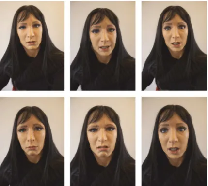
FACE can express and modulate the six basic emotions (happiness, sadness, sur-prise, anger, disgust, fear) in a repeatable and flexible way via an artificial muscular architecture and servo motors. This process can be controlled thanks to the above mentioned artificial skin consisting of 3D latex foam equipped with a biomimetic system of proprioceptive mapping. The sensing layer responds to simultaneous de-formations in different directions by means of a piezoresistive network which consists of a carbon rubber mixture screen printed onto a cotton lycra fabric. These sensors
2.1. COMMUNICATION PROTOCOL 15
Fig. 2.2: The six basic emotions of FACE
2.1
Communication protocol
The actuating system of the robot is controlled by a SSC-32 serial servo con-troller [Lyna]. As already mentioned, the 32 servos provide precise control using a signal that consists of a positive pulse ranging from 0.50 ms to 2.50 ms long which
corresponds to about 180◦. A unique Group Move allows any combination of servos
to begin and end motion at the same time, even if the servos have to move different distances.
All SSC-32 commands are ASCII strings.
Summarizing, the main commands of the communication protocol are the fol-lowing:
• Servo Move or Group Move. The format of a Servo or Group move is #<ch> P<pw> S<spd> ... #<ch> P<pw> S<spd> T<time> <cr>
where:
– <ch> is the channel number in decimal, 0-31 – <pw> is the pulse width in microseconds, 500-2500
16 CHAPTER 2. FACE PROJECT
– <spd> is the movement speed in us per second for one channel (Optional) – <time> is the time in ms for the entire move, affects all channels, 65535
max (Optional)
– <cr> is the carriage return character, ASCII 13 (Required to initiate action)
– <esc> cancel the current action, ASCII 27
Multiple commands of the same type can be issued simultaneously in a Com-mand Group so a configuration can have at most 32 comCom-mands at time. All the commands in a Command Group will be executed after the final carriage return is received.
It is possible to specify a time for the entire configuration or a speed for each servo. Considering that 1000 us of travel will result in around 90◦ of rotation,
a speed value of 100 us per second means the servo will take 10 seconds to
move 90◦. Alternately, a speed value of 2000 us per second equates to 500 ms
to move 90◦.
For example:
#5 P1600 S750 <cr> : this command will move the servo on channel 5 to
position 1600. It will move from its current position at a rate of 750 us per second until it reaches its commanded destination.
#5 P1600 T1000 <cr> : this command will move servo 5 to position 1600. It will take 1 second to complete the move regardless of how far the servo has to travel to reach the destination.
All the servos will start and stop moving at the same time. The time to complete the movement is the time of the slowest servo and it depends on its own initial position.
It is possible to combine the speed and time commands. In this case the speed for each servo will be calculated according to the following rules:
1. All channels will start and end the move simultaneously.
2. If a speed is specified for a servo, it will not move any faster than the speed specified (but it might move slower if the time command requires). 3. If a time is specified for the move, then the move will take at least the amount of time specified (but might take longer if the speed command requires).
2.2. THE MEDICAL ENVIRONMENT 17
• Software Position Offset. This command has the following format #<ch> PO<offset value> ... #< ch> PO<offset value> <cr> where:
– <ch> is the channel number in decimal, 0-31 – <offset value> a number from 100 to -100 in us
– <cr> is the carriage return character, ASCII 13 (Required to initiate action)
This command allows the servos centered (1500 us) position to be aligned perfectly. The servo channel will be offset by the amount indicated in offset value. This represents approximately 15◦ of range. It is important to build the
mechanical assembly as close as possible to the desired centered position before applying the servo offset. The Position Offset command should be issued only once. When the SSC-32 is turned off it will forget the Position Offsets.
For the complete SSC-32 communication protocol see Appendix A.
2.2
The medical environment
The recent technological and engineer developments allow to adopt a more natu-ralistic setting in order to help children with ASD to learn, interpret, use and extend emotional information in a typical social context. The FACE android is used to en-gage the child in simple interactions based on exchange of emotions and learning emotions through imitation of the android’s facial expressions and behaviors. FACE can also be employed in more complex situations, through the recreation of social and emotive scenarios which can be used to motivate and anticipate actions of a subject [PIS+08].
The environment is perceived through a number of different sensors, in part mounted on the android, in part on the surrounding environment and in part on the autistic patient. The android has a CCD camera in the right eye used for the face tracking of the subject. The CCD camera signal is digitalized with a high resolution USB video grabber connected to the FACE control unit and used to drive the OpenCV based face tracking algorithm. The FACET room is equipped with motorized cameras and directional microphones that allow visual monitoring of the subject’s behavior and actions during the therapy.
18 CHAPTER 2. FACE PROJECT
Finally, physiological and behavioral information from the patient is acquired in real time by means of unobtrusive sensitized wearable interfaces during treatment. The monitoring devices include a life-shirt and a gaze tracking cap.
The Smartex T-shirt integrates smart sensors within a garment together with on-body signal conditioning and pre-elaboration, as well as the management of the energy consumption and the wireless communication systems. Three key points make up the sensing shirt: the fabric electrodes based on interconnecting conduc-tive fibers, a piezoresisconduc-tive network and a wearable wireless communication unit. Electrodes and connections are interwoven within the textile by means of natural and synthetic conductive yarns. Their suitable positioning provides real-time acqui-sition of the electrocardiogram, skin conductance, skin temperature and respiratory data, all of which are known to be bodily correlates of emotional states.
Gaze tracking is a critical and useful indicator of a subject’s interest and emo-tional involvement during a therapeutic session with FACE. The cap is HATCAM, a wearable device that was specifically designed to investigate early attention dis-orders in infants. The HATCAM device was designed following some important features. It is wearable, few obtrusive and aesthetic. It has weight below 100g and eye and head tracking capabilities with wireless communication protocol. Basically HATCAM consists of a child-sized cap or head band with a brim, on which a small rectangular mirror is fixed directed towards the wearer’s eyes. An opening in the brim directs the reflection from the mirror to a small video camera attached to the top of the cap. In this way, the direction of the pupils with respect to the subject’s head is constantly monitored and recorded. At the same time a 3 axis inertial plat-form maintains inplat-formation on the orientation of the head, and together the 2 sets of data provide information on eye gaze within the framework of the therapeutic
2.2. THE MEDICAL ENVIRONMENT 19
20 CHAPTER 2. FACE PROJECT
Chapter 3
Implementation
3.1
Software development
As already explained in the previous chapter, the project environment includes not only the robot but also a variety of sensors to be controlled, such as video and audio devices used to control therapies and sensitized wearable clothes used to gather physiological information. Therefore this thesis concerns the development of a software infrastructure capable to manage the great set of data coming from these sensors. This infrastructure includes:
• a software framework for controlling the servo motors actuating FACE, re-sponsible for defining facial expressions of the android (sections 3.1.1, 3.1.2, 3.1.3 and 3.1.4);
• a set of tools allowing psychologists to manage the robot during therapy ses-sions and to analyze acquired data, such as physiological signals and recorded videos (sections3.1.5 and 3.1.6);
• a 3D simulator of FACE allowing therapists to prepare expressions and facial behaviors even off-line in a compatible way with the capabilities of the real robot (sections3.1.7 and 3.1.8).
The software structure of the entire project is shown in Fig. 3.1.
3.1.1
FACELibrary
FACELibrary represents the software core structure which allows to control the 32 servo motors actuating the robot.
22 CHAPTER 3. IMPLEMENTATION
Fig. 3.1: FACE software infrastructure
Humans are sophisticated autonomous agents that are able to work in complex environments through a combination of reactive behavior and deliberative reason-ing. A control system for an autonomous mobile robot must perform many complex information processing tasks in real time. A robot typically has a number of inputs and outputs that must be handled simultaneously and it operates in an environ-ment where the boundary conditions, which are determined through its sensors, are changing rapidly. The robot must be able to react to these changes reaching a stable state.
Over the years, many approaches have been used in artificial intelligence to control robotic machines.
In the early days of mobile robotic research, the starting point for building an in-telligence machine was in most case an engineering background. Before the artificial intelligence, the cybernetics was the application of the control theory to complex systems. The goal was to define a control function and a set of control parameters in such a manner that the system should respond appropriately to sensor stimuli: intelligence was the minimization of an error function.