Scuola di Ingegneria Industriale e dell’Informazione
Master School in Mechanical Engineering
Bandwidth-optimized force platform for a
multiaxial shaker
Supervisor: Prof. Marco TARABINI
Co-Supervisors: Eng. Pietro MARZAROLI
Eng. Stefano MARELLI
M.Sc. thesis by
Alberto Fontanieri
ID number: 893758
Acknowledgements
_________________________________________________________________________
I
Table of contents _________________________________________________________________________ II
Table of contents
Abstract ... VIII Sommario ... VIII Chapter 1Introduction and state of art ... 1
1.1 Shakers classification and main applications ... 1
1.1.1 Commercially available shakers ... 3
1.1.2 Shakers for research and safety applications ... 5
1.2 Serial and parallel robots: an overview ... 7
1.3 The current version of the ED shaker ... 9
1.4 Vibrations measurements for HSW ... 11
1.4.1 Vibrating phenomena and interaction with human body ... 11
1.4.2 Vibration work-related diseases and legislation ... 12
1.4.3 WBV and discomfort on standing people: the Shibata’s experiment ... 13
1.4.4 Apparent mass experiments and WBV ... 14
1.5 Force measurements ... 15
1.5.1 Force sensors overview ... 15
1.5.2 Multiaxial load cells and their applications ... 16
1.5.3 The studies on the Stewart’s platform as a force sensor ... 19
1.6 Purposes of this thesis ... 21
Chapter 2 Shaker bandwidth optimization ... 22
2.1 Introduction and methods ... 22
2.2 Platform optimization ... 24
2.2.1 Thickness reduction ... 24
2.2.2 Double chamfering of platform external sides ... 26
2.2.3 Material changes ... 27
2.3 Connectors optimization ... 29
2.4 Shafts optimization ... 31
2.5 Wedges optimization ... 32
2.6 Effect of sliders stiffness ... 32
2.7 Other structural improvements ... 33
Chapter 3 Platform optimization ... 35
Table of contents
_________________________________________________________________________
III
3.2 Geometry optimization ... 36
3.3 Material choice ... 37
3.4 FEM model definition ... 38
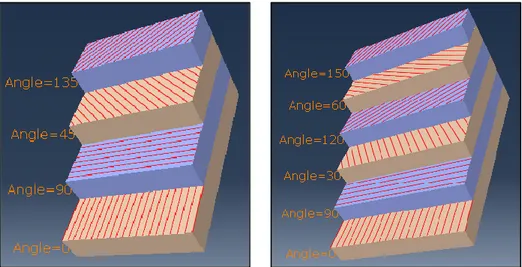
3.4.1 Skins and orientation ... 38
3.4.2 Assembly ... 40
3.4.3 Constraints and mesh ... 41
3.5 Optimal parameter definition through FEM modal analysis ... 42
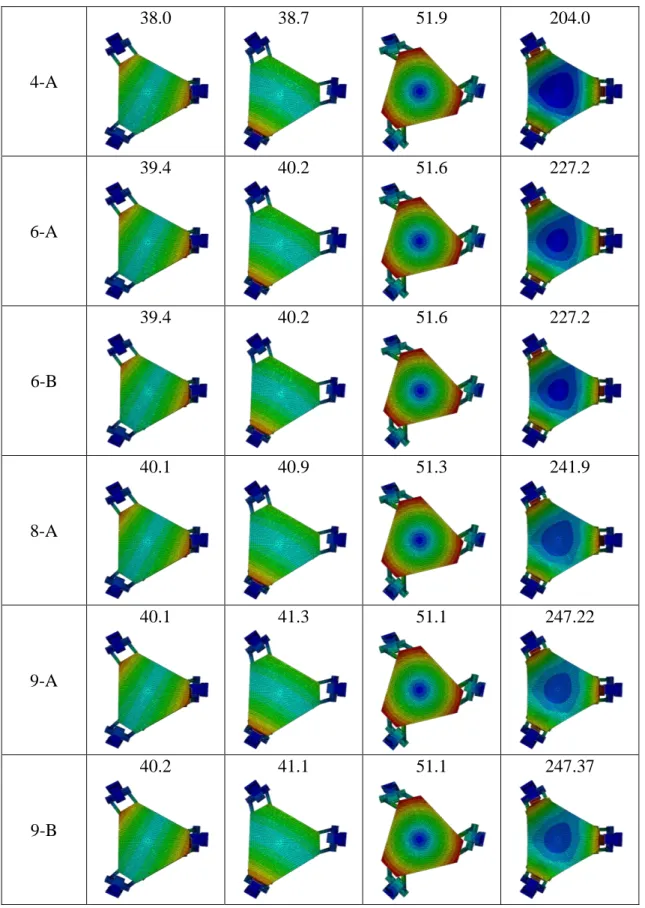
3.5.1 Number and pattern of skin layers ... 43
3.5.2 Thickness of the aluminum honeycomb layer ... 45
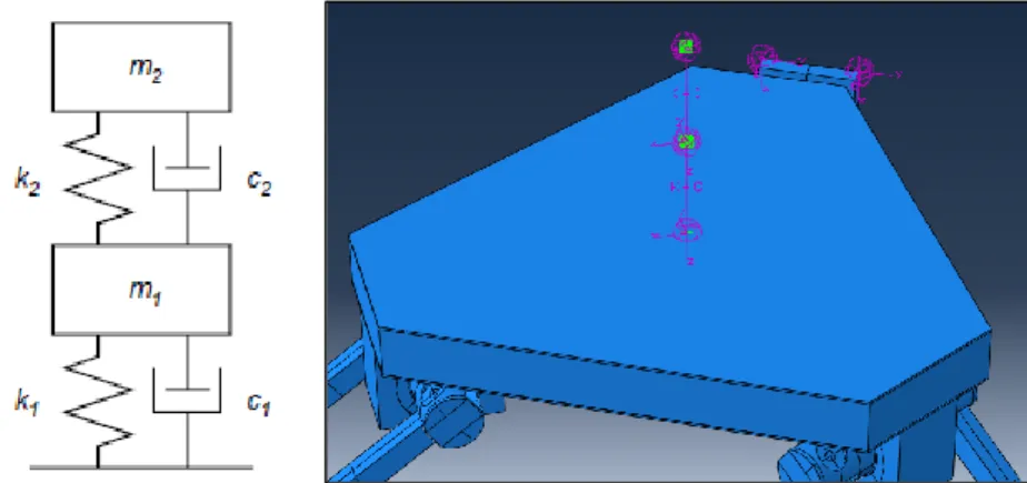
3.6 Effect of the apparent mass ... 48
3.7 Static model ... 50
3.7.1 Weight distributed on two footprints... 50
3.7.2 Weight distributed on a single footprint ... 52
Chapter 4 Static equilibrium of forces and instability ... 55
4.1 Introduction and previous works ... 55
4.2 Transportation of the forces acting on the structure ... 56
4.3 Singularities and conditioning problems ... 65
4.3.1 The Dwarakanath’s studies on singularities ... 65
4.3.2 Conditions of instability of the old version of the shaker ... 66
Chapter 5 Design of the force platform ... 69
5.1 Wheatstone’s bridge and strain gauges overview ... 69
5.1.1 The Wheatstone’s bridge ... 69
5.1.2 Strain gauge working principle ... 70
5.1.3 Configuration for axial strain measurement ... 71
5.2 Experimental equipment ... 72
5.3 Floor noise evaluation ... 73
5.4 Preliminary experiments ... 75
5.4.1 Strain gauges installation ... 75
5.4.2 Methodology ... 76
5.4.3 Results ... 77
5.4.4 Calibration curve ... 79
5.5 MonteCarlo simulations for error propagation ... 83
5.5.1 Methodology ... 83
Table of contents
_________________________________________________________________________
IV Chapter 6
Discussion and future developments ... 88
6.1 Installation of strain gauge bridges on all the links ... 88
6.2 RC circuit for low-pass filter installation ... 88
6.3 Sensitivity improvement and amplification ... 89
6.3.1 Notch model ... 90
Conclusions and remarks ... 93
Appendix A Platform mechanical drawings ... 94
Appendix B MATLAB® script for instability ... 95
Appendix C MATLAB® script for MonteCarlo simulation ... 97
List of figures
_________________________________________________________________________
V
List of figures
Figure 1: TeamCorporation’s hydraulic shakers: a) Mantis™; b) The Cube®; c) Tensor™ ... 3
Figure 2: MAST™ family’s hydraulic shakers: a) Orthogonal; b) Hexapod ... 4
Figure 3: ED shakers: a) Sentek Electronics’ MA-Series™; b) IMV Corporation’s TS-Series™ .... 4
Figure 4: CALCE’s M-DOF shaker (College Park, MD, United States) ... 5
Figure 5: MAST™353 at INAIL Research Center (Monte Porzio Catone, Italy) ... 6
Figure 6: Industrial manipulators: a) Serial robot; b) Parallel robot ... 7
Figure 7: Clavel’s Delta robots: a) Linear; b) Revolute ... 9
Figure 8: Current version of the ED shaker: a) Side view; b) Top view ... 9
Figure 9: Current version of the ED shaker: CAD model ... 10
Figure 10: MSDs: a) Causes for MSDs in the EU; b) Activities exposed to vibrations ... 12
Figure 11: Shibata's experimental test setup ... 13
Figure 12: Monoaxial load cells: a) Tension/Compression; b) Bending; c) Torsion ... 15
Figure 13: Tactile load cells: artificial fingers ... 15
Figure 14: Multiaxial load cells ... 16
Figure 15: Gough-Stewart’s platform examples ... 18
Figure 16: Single DOF undamped mechanical system ... 22
Figure 17: Double-chamfered platform ... 27
Figure 18: Chamfering of the cubes: a) Sketch; b) Cubes on platform; c) Cubes on sliders ... 30
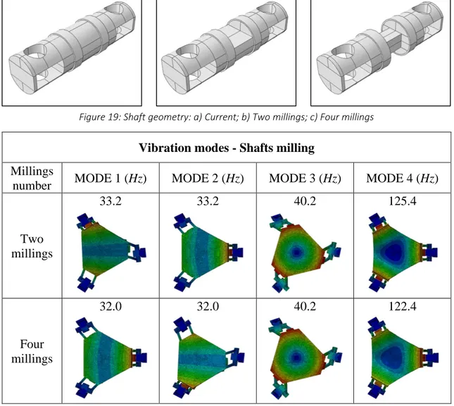
Figure 19: Shaft geometry: a) Current; b) Two millings; c) Four millings ... 31
Figure 20: Virtual springs on the sliders: a) Side view; b) Top view... 32
Figure 21: Fixed kinematical parameters ... 35
Figure 22: The current platform: a) Top view; b) Bottom view ... 36
Figure 23: The new platform (top view) ... 37
Figure 24: ABAQUS® - Local reference system of a skin ... 39
Figure 25: ABAQUS® - Composite layup: a) Pattern A; b) Pattern B ... 40
Figure 26: ABAQUS® - Sandwich panel model ... 41
Figure 27: ABAQUS® - Face-to-face positional constraint ... 41
Figure 28: ABAQUS® - Tie constraint ... 42
Figure 29: First Mode frequency vs Number of carbon fiber woven layers ... 45
Figure 30: First Mode frequency vs Total platform thickness ... 47
Figure 31: Matsumoto and Griffin: a) Human body scheme; b) FEM model of human body ... 49
Figure 32: ABAQUS® - Load application on two footprints: a) Model; b) Commands ... 51
Figure 33: Static loading, two feet - Max principal stress: a) Global top view; b) Bottom view ... 51
Figure 34: Static loading, two feet - Max deflection on the whole structure ... 52
Figure 35: Static loading, two feet - Max deflection on the platform only (Bottom view) ... 52
Figure 36: Static loading, one foot - Max principal stress: a) Global top view; b) Bottom view .... 53
Figure 37: Static loading, one foot - Max deflection on the whole structure ... 53
Figure 38: Static loading, one foot - Max deflection on the platform only (Bottom view) ... 54
Figure 39: Link angles: a) i on the xy plane; b) i on the xz plane ... 56
Figure 40: Reference frames - a) Link centre: {xL yL zL}; b) Bearings centre: {xB yB zB}... 57
Figure 41: Reference frames - Cube centre: {xC yC zC} ... 58
Figure 42: Reference frames - Translations: {xBLC yBLC zBLC}, {xTLC yTLC zTLC}, {xS yS zS} ... 59
Figure 43: Reference frames - Central {xP yP zP} and peripheral {xS yS zS} frames on the platform 62 Figure 44: The old version of the shaker: a) Single link; b) Assembly ... 66
List of figures
_________________________________________________________________________
VI
Figure 46: Examples of strain gauges ... 71
Figure 47: Full bridge type III: a) Gauges arrangement on a beam; b) Electrical scheme ... 71
Figure 48: National Instruments’ 9237 simultaneous bridge module ... 73
Figure 49: Floor noise evaluation - a) Setup; b) Top view; c) Bottom view ... 73
Figure 50: Floor noise evaluation - First series ... 74
Figure 51: Floor noise evaluation - Second series ... 74
Figure 52: Floor noise evaluation - Third series ... 74
Figure 53: Strain gauges installation on a link: a) Left view; b) Right view ... 76
Figure 54: Signal acquisition - Continuous series ... 77
Figure 55: Signal acquisition - First series ... 77
Figure 56: Signal acquisition - Second series ... 78
Figure 57: Signal acquisition - Third series ... 78
Figure 58: Signal acquisition - Scatterplot with error bands ... 80
Figure 59: Signal acquisition - Calibration curve and uncertainty bands (plot) ... 82
Figure 60: Normal distributions from histograms for the measured force components ... 87
Figure 61: RC circuit for low-pass filter installation ... 89
Figure 62: Link geometry: a) Full section; b) Notched section ... 90
Figure 63: Notch coefficient kt diagram [65] ... 91
Figure 64: Measured forces vs Notch diameter for fixed strain values ... 91
List of tables
_________________________________________________________________________
VII
List of tables
Table 1: Shakers classification ... 1
Table 2: Features of TeamCorporation’s shakers [3] ... 3
Table 3: MAST™ 353 dimensions and rototranslational performances [9] ... 6
Table 4: Features of serial and parallel robots [11] ... 8
Table 5: Current masses of the shaker components ... 23
Table 6: First four vibration modes of the current shaker version ... 24
Table 7: Vibration modes - Platform thickness reduction ... 25
Table 8: Vibration modes - Double chamfering of platform external sides ... 27
Table 9: Material density and Young's modulus changes ... 27
Table 10: Vibration modes - Platform material changes ... 29
Table 11: Vibration modes - Chamfering of cubes external sides ... 30
Table 12: Vibration modes - Shafts milling ... 31
Table 13: Vibration modes - Wedges removal ... 32
Table 14: Vibration modes - Block of sliders rotation ... 33
Table 15: Vibration modes - Mixed modifications effects on bandwidth ... 34
Table 16: Elastic properties of aluminum honeycomb [59] ... 37
Table 17: Elastic properties of HM carbon fiber [60] [61] ... 38
Table 18: Pattern A for composite layup ... 40
Table 19: Pattern B for composite layup ... 40
Table 20: Relative tie constraints of composite layup ... 42
Table 21: Vibration modes - Changes in number and pattern of skin layers ... 44
Table 22: Vibration modes - Changes in total platform thickness ... 47
Table 23: Mass-normalized parameters for Matsumoto and Griffin’s model ... 49
Table 24: Vibration modes - Standing subject and platform ... 50
Table 25: HBM’s LY-41 10/120 strain gauge features ... 72
Table 26: Floor noise evaluation - Variance and RMS of the three series ... 75
Table 27: MeasLab© setup for signal acquisition ... 76
Table 28: Mean and standard deviation of the first series of signals ... 79
Table 29: Mean and standard deviation of the second series of signals ... 79
Table 30: Mean and standard deviation of the third series of signals ... 80
Table 31: Signal acquisition - Calibration curve and uncertainty bands (values) ... 83
Table 32: MSEs from MonteCarlo simulations ... 85
Table 33: Normal distributions parameters of Figure 60 ... 86
Table 34: Geometric and elastic properties of a link ... 90
Abstract - Sommario
_________________________________________________________________________
VIII
Abstract
Sommario
The aim of this work is to improve the dynamic performances and the bandwidth of a novel multiaxial shaker, to be employed for measuring the three-dimensional apparent mass of a standing person subjected to vibrations. In particular, the first part of the thesis involves the employment of lightweight design principles and composite materials, with the aim of optimizing the mass and the stiffness of the moving parts of the structure: hence, a series of numerical simulations would address the most effective changes to be applied in order to enlarge the system bandwidth. Then, the second part of the work focuses on the implementation of a force measurement system to be installed on the same structure, intended to convert the shaker in a force-sensing platform. The proposed system would allow the measurement of the three spatial components of the force and torque vectors generated at the centre of the moving platform by a standing human body subjected to multiaxial vibrations, thus allowing the evaluation of its apparent mass.
Il presente lavoro si propone di migliorare le prestazioni dinamiche e la banda passante di uno shaker multiassiale, atto a misurare la massa apparente tridimensionale di una persona in postura eretta soggetta a vibrazioni. Nel dettaglio, la prima parte della tesi si fonda sull’utilizzo dei principi del lightweight design e sull’impiego dei materiali compositi, con lo scopo di ottimizzare la massa e la rigidezza delle parti sospese della struttura. Pertanto, grazie all’utilizzo di una serie di simulazioni numeriche, sono state individuate le modifiche più efficaci da apportare al sistema, al fine di incrementarne la banda passante. La seconda parte del lavoro, invece, prevede la trasformazione dello shaker in un sensore di forza, in grado di misurare, lungo i tre assi coordinati, le forze e i momenti generati da una persona in piedi soggetta a vibrazioni multiassiali, facilitandone così la determinazione della massa apparente tridimensionale.
Keywords: multiaxial shaker, apparent mass, lightweight design, FEM simulations, force platform, MonteCarlo method.
Chapter 1 Introduction and state of art
_________________________________________________________________________
1
Chapter 1
Introduction and state of art
1.1 Shakers classification and main applications
A shaker is a mechanical device that allows to perform vibration tests on an entity, either simulating the actual environmental conditions (field-dependent testing) or focusing on the product weaknesses that may lead to a failure (product-dependent testing) [1]. The shakers can be classified in function of the number of vibrating axes and of the actuating system that provides the excitation, as shown in Table 1:
Shakers classification Actuating system Hydraulic Electrodynamic Number of axes Monoaxial Multiaxial
Table 1: Shakers classification
In detail, a monoaxial shaker (also called linear) can generate a mechanical oscillation, either sinusoidal, random or deterministic, along only one axis. The multiaxial response of the object to be tested is estimated as the sum of the responses along each direction of excitation. However, the concurrent effect of triaxial vibrations is often different from the sum of the effects due to subsequent uniaxial excitations. Moreover, being the latter highly dependent
Chapter 1 Introduction and state of art
_________________________________________________________________________
2
on the time history of the excitation signal, a significant variance in time-to-failure can be observed. For these reasons, the multiaxial shakers have been developed, particularly succeeding in the aerospace and automotive fields, being pushed by the growing needs for product quality and in presence of particular tests, where [1]:
• A single attachment point could damage the test article when applying the loading forces (e.g. long missiles)
• The physical configuration of the unit under test required a greatly expensive fixture • The required force was greater than the one available from a single shaker
• More waveforms needed to be simulated at the same time and at different locations of a large structure
Additionally, the multiaxial shakers further split into two main families, depending on the typology of actuating device. In particular [2]:
• Hydraulic shakers: the end-effector of the shaker is moved through hydraulic actuators, each one controlled by a servo-valve. The motion of the pistons is obtained through negative or positive voltage control, for downwards and upwards movements respectively, while the voltage signal is generated by means of a frequency generator.
• Electrodynamic (ED) shakers: each motor has a frequency generator that sends a signal to a current amplifier, thus creating an electromagnetic force. This force drives the armature of the shaker along the field coils, which are large polarized electromagnets within the shaker body.
The proposed classification groups the great part of the existing shakers, although some differences still hold between the industrial and academic worlds, due to different purposes and employment. Therefore, the subsequent paragraphs are intended to address some basic distinctions among the commercially available shakers and the devices for research applications, with particular mention to laboratories and testing centers.
Chapter 1 Introduction and state of art
_________________________________________________________________________
3
1.1.1 Commercially available shakers
Nowadays, many different models of shakers are commercially available, each one suitable for specific testing purposes. In particular, the models gathered in Table 2, provided by one of the main manufacturers of the sector (TeamCorporation), can be assumed as a valid overview of the present state of art, with particular reference to the hydraulic devices [3]:
Table 2: Features of TeamCorporation’s shakers [3]
As inferred from Table 2, the values of force rating, stroke and admissible payload are strictly related, increasing with the size of the shaker. Instead, greater, heavier structures involve a narrower frequency bandwidth, that reduce the adaptability of the shaker to a wide range of testing fields. In Figure 1, the just-mentioned hydraulic shakers are shown:
Figure 1: TeamCorporation’s hydraulic shakers: a) Mantis™; b) The Cube®; c) Tensor™
Furthermore, among the hydraulic shakers, the MTS Systems’ trademark Multiaxial
Simulation Tables (MAST™) includes bulky platforms, suitable for testing heavy structures
at low or medium frequencies in presence of high forces and significant stroke length. Among them, the orthogonal platforms can reach up to 50 Hz of excitation, while the
Chapter 1 Introduction and state of art
_________________________________________________________________________
4
Figure 2: MAST™ family’s hydraulic shakers: a) Orthogonal; b) Hexapod
Nowadays, for not particularly demanding applications, the electrodynamic shakers gained more popularity, because they are more compact and cost-effective than the hydraulic ones. In fact, with respect to the hydraulic devices, they require less maintenance, providing also a greater bandwidth of excitation and a faster response in frequency control [2].
Among the most important producers, Sentek Electronics developed the MA-Series™, in which three ED shakers provide the motion, through the application of forces that range from 10 to 60 kN, for a testing bandwidth of 2 kHz [5]. Similar devices have been proposed by
IMV Corporation: their TS-Series™ allow a high grade of customization, offering a broad
selection of shakers that provide forces from 9 to 95 kN, and up to 1 kHz of excitation bandwidth [6]. Both the described products are then shown in Figure 3:
Figure 3: ED shakers: a) Sentek Electronics’ MA-Series™; b) IMV Corporation’s TS-Series™
After explaining the main features of the commercial devices, it is worth to move on the research laboratories, where shakers are employed for academic purposes or to perform on-commission tests for ministerial or public entities, especially in the health and safety at work (HSW) field.
Chapter 1 Introduction and state of art
_________________________________________________________________________
5
1.1.2 Shakers for research and safety applications
As inferred from the previous paragraph, commercially available ED shakers can provide excitation over three axes at most, but in research laboratories also multiple degrees of
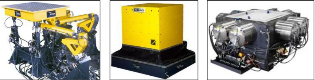
freedom (M-DOF) systems have been developed. In fact, as stated in [7], the Center for Advanced Life Cycle Engineering (CALCE) in Maryland employs the particular ED shaker
shown in Figure 4, employed for simulating the damages occurring in a battlefield context. The equipment is characterized by eight in-plane and four out-of-plane actuators, the latter lying under the table. This way, each one of the three axes has got four shakers that can be excited independently up to an acceleration of 30 G and a frequency of 3 kHz. Moreover, an excellent control of the excitation profile shape, jointly with the perfect coherence between the axes arises from the plots reported in [7]. All these features allow the identification of the main failure mechanisms of the system, by pointing out the DOF that stirs up higher damages to the components after a firefight in a battlefield.
Figure 4: CALCE’s M-DOF shaker (College Park, MD, United States)
Anyway, a multiaxial shaker would require a large amount of space and controlled field conditions to properly simulate the vibrating environment: therefore, only few laboratories own the adequate room to host a shaker as the one shown in Figure 5, located at the Italian
Workers’ Compensation Authority (INAIL) Research Center in Monte Porzio Catone,
Rome. In this Institute, known for its research on work-related accidents and diseases, many vibration tests have been performed on standing and seated subjects, but also on medium-sized machinery, and then gathered in the National Institute of Occupational Prevention and
Safety (ISPESL) vibration database, as mentioned in [8]. For these purposes, a hydraulic MAST™ 353 has been employed, entailing a maximum payload of 680 kg, to be applied on
Chapter 1 Introduction and state of art
_________________________________________________________________________
6
an excitation range of frequencies from 0.1 to 100 Hz, while its dimensions and its rototranslational performances are shown in Table 3:
Features Direction
Machine dimensions Height Width Length
Size 1.32 m 3.3 m 3.7 m
Translational performance Vertical Lateral Longitudinal
Double amplitude displacement 300 mm 300 mm 200 mm
Velocity 1 m/s 0.9 m/s 0.9 m/s
Max acceleration (max payload) 4 G 3 G 3 G
Max acceleration (no payload) 6 G 6 G 5 G
Rotational performance Yaw Pitch Roll
Tilting angle ± 6.0° ± 7.0° ± 7.0°
Table 3: MAST™ 353 dimensions and rototranslational performances [9]
Figure 5: MAST™353 at INAIL Research Center (Monte Porzio Catone, Italy)
As mentioned before, not all the laboratories own the necessary room to host such a structure, also because, in order to avoid any undesired vibration, the optimal positioning for the shaker would be embedded in the ground, thus calling for a meter-deep dig on the floor.
For these reasons, alternative structural solutions have been developed to perform the same kind of tests and measurements, in order to optimize costs and space utilization. Many examples in this field exploit a robotic architecture, that provides compact devices with a high grade of customization, as explained in the brief overview proposed in the following paragraph.
Chapter 1 Introduction and state of art
_________________________________________________________________________
7
1.2 Serial and parallel robots: an overview
According to the Robotic Institute of America (RIA), a robot can be defined as “a reprogrammable, multifunctional manipulator designed to move materials, parts, tools or specialized devices through variable programmed motions for the performance of a variety of tasks” [10]. These entities can be divided in two main categories:
• Serial manipulators (Figure 6a): consist in several links connected in series by various types of joints, typically revolute and prismatic. One end of the robot (called
base) is fixed to the ground, while the other end (end-effector) is free to move in
space. Typically, a gripper or a mechanical hand is attached to the end-effector. • Parallel manipulators (Figure 6b): consist in two or more closed-loop kinematic
chains in which the end-effector (mobile platform) is connected to the fixed base platform by, at least, two independent kinematic chains. Then, between the base and the end-effector platforms, some serial chains (called limbs or legs) are installed.
Figure 6: Industrial manipulators: a) Serial robot; b) Parallel robot
Moreover, Table 4 shows up the main differences between the two robot typologies. In detail, serial manipulators are suitable for repetitive tasks over long periods of time, operations in hazardous environments (exposed to nuclear radiation, performed underwater, related to space exploration…) and precision works with high degree of reliability. Some examples of their applications are welding, painting, polishing, injection molding, laser and plasma cutting, assembly, packaging and material handling. Instead, parallel robots ensure high accuracy, rigidity, speed and large load-carrying capability, although implying more complex kinematics, dynamics and smaller workspace. The current industrial applications
Chapter 1 Introduction and state of art
_________________________________________________________________________
8
of parallel robots lie in fine positioning devices, simulators, moving platforms, machine tools, pick-and-place tasks, medical applications and force-sensing purposes [11].
Table 4: Features of serial and parallel robots [11]
Among the parallel manipulators, the Clavel’s Delta robot is surely the most successful layout. This device is made up of two platforms (one fixed to the ground, one moving in space) mutually connected by a series of links. The moving platform is forced to remain parallel to the ground, by means of linkages arranged in a triple parallelogram structure. Additionally, in function of the joint typology, the Delta robot can be linear when it uses prismatic joints (the three translational DOFs are q1, q2 and q3), or revolute if it employs spherical joints (the three rotational DOFs are and ) The two different typologies are then shown in Figure 7:
Chapter 1 Introduction and state of art
_________________________________________________________________________
9
Figure 7: Clavel’s Delta robots: a) Linear; b) Revolute
Hence, the compact design and the high stiffness of linear Delta robots, jointly with their identical performances on every horizontal working plane and the chance of a relatively large vertical displacement (up to 60 mm for the most common devices [12]), threw the basis for the development of the shaker hosted in Lecco Campus of Politecnico di Milano, starting point of the present work. This way, the room-related issues of multiaxial shakers have been partially solved.
1.3 The current version of the ED shaker
Starting from the design of a linear Delta robot, a novel multiaxial ED shaker has been developed by Marzaroli in 2017 [13]. This compact structure allows to perform laboratory tests without needing a dedicated room, thus saving on space and costs. In Figure 8, the current version of the shaker is displayed:
Chapter 1 Introduction and state of art
_________________________________________________________________________
10
Three brushless motors OMRON R88M-M3K020C (400 V, 3 kW) jointed to three ballscrews provide the actuation force. The ballscrews are held by aluminum vertical columns, which are placed on a grounded steel basement and linked each other by horizontal stiffening bars. Each actuator is equipped with a slider, that moves up and down proper guiding grooves on the columnar body. Then, an aluminum hollow cube is mounted on each slider, hosting two
SKF 32912, tapered, single row roller bearings, whose inner ring is in contact with an
aluminum shaft, properly modeled with two grooves at its extremities. In fact, each slot has to allow the in-plane rotation of the prismatic aluminum links, which occurs around a steel pin. This pin is connected to the shaft body by means of two SKF BEP 7200, angular contact, single row ball bearings. On the other extremity of each link, the same bearings, shafts, pins and cubes are installed: the latter cubes, then, are all connected to a moving platform by means of three aluminum wedges. Finally, the platform is made of an aluminum plate, with a thickness of 25 mm, presenting ribs and grooves on its bottom face, aimed to remove superfluous material and to maintain the right amount of stiffness [14]. Additionally, a
Computer Aided Design (CAD) model of the shaker is shown in Figure 9:
Figure 9: Current version of the ED shaker: CAD model
Then, once described the structural features of the current shaker, it is worth to underline its main functionalities. In fact, as mentioned in the paragraph 1.1.2, multiaxial ED shakers can be successfully employed in the measurement of vibrations that affect the human body, with special attention to the HSW. Thus, also this structure was initially intended to perform this kind of measurements, with particular reference to the whole-body vibrations (WBV), as inferred from the studies carried out by Marzaroli [13] and others [14] [15] [16]. Anyway, a
Chapter 1 Introduction and state of art
_________________________________________________________________________
11
similar equipment can be also employed as an autonomous multiaxial force sensing structure, through a calibration process which would relate the measured loads to the actual ones. For these reasons, an overview of both vibration and force measurements will be provided in the next paragraphs.
1.4 Vibrations measurements for HSW
1.4.1 Vibrating phenomena and interaction with human body
Vibration is a mechanical phenomenon whereby oscillations occur around an equilibrium point, in a periodic or random fashion. Depending on which forces are acting on the body, two definition of vibration exist: free vibration, when only internal forces make the system oscillate, and forced vibration, when the phenomenon is caused by external forces [17]. Nowadays, the increasing usage of powerful tools in workplaces involves a higher generation and transfer of mechanical and acoustical vibrations to the human workers. Indeed, the ground is able to damp only a portion of the vibration energy, while the remaining part inevitably reaches the nearby workers’ bodies, compressing their tissues and organs [18]. Thus, scientific research [19] [20] grew its interest in this field, demonstrating that the most relevant parameters in the human-wave interaction are the exposure time, combined with frequency and magnitude of the vibration. Indeed, prolonged exposure, higher amplitudes and the presence of sudden shocks may represent a health risk for the human body, especially for the muscles. In fact, their contraction (voluntary or not) helps in the vibration energy absorption, but results in a local fatigue tension, which also wears the joints cartilage, whose purpose lies in smoothing the relative motion between bones and muscles themselves.
The effects of vibrations on humans range from simple stress and annoyance, to harmful mechanical damages, caused by resonance within various organs. Namely, resonance occurs when the vibration frequency and the natural frequency of a body coincide, thus generating large oscillations within the body itself, with potentially catastrophic effects. Moreover, each part of the body can act as a vibrating entity by itself, with its own range of resonance frequencies [21], which can be observed in a detailed table provided by Wieckowski [22]. The assumption of independent behavior of the body parts is valid for excitation frequencies that range from 2 to 80 Hz, while for frequencies higher than this threshold, the damping
Chapter 1 Introduction and state of art
_________________________________________________________________________
12
effect of the organs becomes predominant. Instead, for frequencies lower than 2 Hz, body will respond as a homogeneous and unique mass [23].
1.4.2 Vibration work-related diseases and legislation
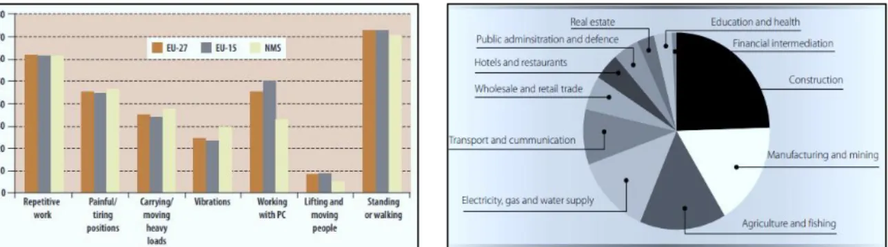
Recent studies by the European Agency for Safety and Health at Work (EU-OSHA) [24] demonstrated that the prolonged standing position during the shifts and the poor ergonomic conditions of the workstations, led to a rise of musculoskeletal disorders (MSDs), which account for 38.1% of the occupational diseases in the European Union (EU). In particular, women suffer from MSDs more than men do, generally because occupied in manufacturing activities that require more repetitive tasks, although this fact is still underrecognized. Moreover, the same affection has a rising trend in younger workers, especially if employed in the services or in heavy industries. In detail, Figure 10a shows the main causes for MSDs in the EU, while Figure 10b displays the most exposed sectors of activities:
Figure 10: MSDs: a) Causes for MSDs in the EU; b) Activities exposed to vibrations
Among the main factors for MSDs in the EU, vibrations represent the sixth cause [24], mainly involving sectors like construction (63% of workers affected by), manufacturing and mining (44%), agriculture and fishing (38%), electricity, gas and water supply (34%) and transportation (23%) [25]. For these reasons, proper legislation has been adopted in order to regulate the working environments, providing minimum health and safety requirements and describing the methods and techniques for their evaluation.
Among them, the Directive 2002/44/EC of the European Parliament [26], actuated in Italy through the Legislative Decree 81/2008, Section III [27] establishes the daily exposure limits to hand-arm system vibrations (HAV) and whole-body vibrations (WBV), while other scientific studies also focused on the foot-transmitted vibrations (FTV) [18]. Namely, WBV is defined as “the mechanical vibration that, when transmitted to the whole body, entails
Chapter 1 Introduction and state of art
_________________________________________________________________________
13
risks to the health and safety of workers, in particular lower-back morbidity and trauma of the spine”. Scientific literature too confirms that WBV are one of the main causes for MSDs onset, especially for low-back pain [28] [29] and ailments related to shoulders and neck [30]. The International Standard ISO 2631-1:2014 [31], instead, provides methods and indexes for measuring the acceptance of the vibration levels that interfere with human body. It defines the reference systems to be adopted for measuring linear and rotational vibrations in different body positions, specifying that the origin (namely the contact point between the body and the vibration source) needs to host the transducer [18]. The standard also provides the frequency-weighting curves, which act as a filter on the obtained measurements, fitting them on a human-based scale [32]. Moreover, the root mean square (RMS) value of the signal, properly filtered through the frequency-weighting curves, is employed to compute the vibration exposure A(8) parameter, whose limit and action thresholds are provided by the Standard, in function of the exposure duration [17].
1.4.3 WBV and discomfort on standing people: the Shibata’s experiment
The most recent and complete study of the vibrational effects on standing subjects has been carried out by Shibata [33], with the aim of measuring the discomfort caused by fore-aft, side-side and vertical WBV. In detail, twelve people experienced three levels of acceleration (0.2; 0.4; 0.8 m/s2) in three different directions and, at the end, they fulfilled a form on the perceived discomfort level, according to a semantic scale from 1 (Not uncomfortable) to 5 (Very uncomfortable), properly designed by the author. The experimental setup (Figure 11) consisted of a rigid platform, actuated by seven shakers (two powered in the lateral direction, four in the vertical, and the last in the fore-aft one). A feedback loop controlled the motion of the platform, thanks to seven accelerometers mounted on it.Chapter 1 Introduction and state of art
_________________________________________________________________________
14
The obtained results showed that, for increasing levels of acceleration, the grade of discomfort raised for all the directions of excitation. Moreover, the highest discomfort ratings were registered for the vertical vibrations, then the fore-aft, then the lateral ones. Hence, Shibata demonstrated how to employ a shaker for WBV generation, but further attention needs to be paid on the response that human body offers to such excitation, jointly to the apparent mass effects, studied by Subashi et al. [34]. Indeed, the apparent mass matrix determination becomes crucial for correctly evaluating the human response to WBV, and many research studies have been addressed on it, mainly focusing on its nonlinearity [35].
1.4.4 Apparent mass experiments and WBV
When a structure supports a human body, the dynamic behavior of the two entities can mutually affect. In fact, in presence of a dynamic load, if one of the two entities start to vibrate, the other one would start too, as it happens when a man walks on a bridge, or when a shaker operates with a standing subject on it. In particular, when this occurs, the dynamic response of the overall system to the vibration can experience a 50–100% amplification of its expected value, due to the mutual excitation of the two entities, as in presence of a resonance phenomenon. In these conditions, the structure supporting the human body perceives its mass (thus known as apparent) as it was 1.5-2 times greater than its static value. Therefore, in a vibrational context, the only consideration of the static mass value can lead to an underestimation of the effect that the human body actually has on the structure [36]. According to Subashi et al. [34] and to Matsumoto and Griffin [36], the apparent mass value can be obtained from a series of experiments. Indeed, dynamic loads at five different magnitudes (0.125; 0.25; 0.5; 1; 2 m/s2 RMS) and at random frequencies (from 0.5 Hz to 30 Hz) have been applied through a force platform to a subject standing on it, while accelerometers measured the perceived accelerations for each loading condition. Then, the ratio between the provided force and the measured acceleration for a specific frequency has returned the apparent mass value for that frequency of excitation. Finally, after performing the tests on twelve male subjects, the curves relating the ratio between apparent and static mass in function of the frequency have been derived, showing a resonating peak around 5 Hz. This meant that, for this frequency, the supporting platform perceived the mass of the standing subject as it was almost twice its static value.
Chapter 1 Introduction and state of art
_________________________________________________________________________
15
Therefore, given that the apparent mass evaluation calls for the employment of a force platform, the present work aims for developing a similar structure, which would be able to measure multiaxial loads. Hence, in order to introduce the force measurements, an overview of the most common devices and applications has been provided in the next paragraphs.
1.5 Force measurements
1.5.1 Force sensors overview
The force sensors provide a measurement of the load acting on the structure where the sensor itself is placed. These sensors can be classified in three broad families, in function of the transmitted force and way of application [37]:
• Monoaxial sensors (Figure 12): they can quantify a force/torque applied in only one direction, starting from stress and strain values measured by uniaxial strain gauges mounted on a simple-shaped component. These sensors are cheap, stiff and robust and provide high resolution and reliability, making them suitable for highly accurate static force measurements.
Figure 12: Monoaxial load cells: a) Tension/Compression; b) Bending; c) Torsion
• Tactile force sensors (Figure 13): the force is applied directly on the sensor, which provides a haptic feedback. Usually, arrays of pressure sensors or strain gauges cover the entire surface to be monitored (e.g. artificial skin), transmitting either pressure distribution or force/torque patterns. The tactile load cells have been used in robotics for contact force determination, grasping control and recognition of objects.
Chapter 1 Introduction and state of art
_________________________________________________________________________
16
• Multiaxial sensors (Figure 14): they can measure all the three components of force/torque vectors in space, through the evaluation of the reaction forces of the entity on which they are applied. The fullscale of this kind of sensors can reach the order of magnitude of thousands of Newton of force, and they are particularly suitable for the industrial applications.
Figure 14: Multiaxial load cells
1.5.2 Multiaxial load cells and their applications
Wind tunnel and thrust-stand-testing of rocket engines required multiaxial force transducers since 70s. In fact, the field conditions involved more loads acting on the testing items at the same time, and a monoaxial sensor would not be able to measure them all. Especially robotics witnessed a growing interest in these sensing devices, due to the request of increasingly autonomous and dexterous tasks. Indeed, any manipulator needs to be controlled in terms of positioning of the arms, but only a proper evaluation of the forces and torques acting on them can prevent from any failures due to overloads or fatigue [38]. Unlike the actuators, hidden inside the various parts of the robot, a multiaxial force/torque sensor is located externally, acting as an offshoot which acquires data through an intelligent system and transmits them to the processing unit of the manipulator. Obviously, the whole system is equipped with a compliant structure, which combines sensing elements inside a shielded cover with a flexible cable and the above-mentioned data acquisition center [37].
Surgical and medical worlds: need for precision and sensitivity
Especially surgical and medical rehabilitation worlds noticed great contribution from the adoption of the six-axis load cells. For example, the Shiley Center for Orthopaedic Research
& Education at Scripps Clinic in La Jolla, CA [39] designed a total knee replacement tibial
prosthesis as multiaxial sensor, in order to accurately measure the spatial components of tibial forces, thus evaluating the stress state of the implant. Moreover, in the plastic and
Chapter 1 Introduction and state of art
_________________________________________________________________________
17
reconstructive surgery, the force sensing makes the surgeon aware of applied load on the delicate tissues and prevent him from damage them. Some examples involve the studies of Sommer on the measurement of deformations acting on adipose [40] or esophageal [41] tissues, respectively preventing from a shear excess that would imply unaesthetic scars on skin, or guiding the operation for the implantation of new tissues in babies with congenital defects. Then, research on force sensing of robotic hands has been carried out, thus connecting the worlds of surgery and industry, starting from the studies of Bejczy [42] and arriving to the most recent considerations about gripping items by Hogreve and Tracht [43]. In particular, in order to safely seize, push and pull an unknown object using intelligent fingers, the hand has to perceive the weight, which is calculated from measured forces/torques from a load cell installed on the wrist. G. Kim, in 2007 [44], stressed the fact that the existing manufactured sensors were not proper in size for being mounted on a robotic wrist, thus a six-axis load cell needed to be designed time by time. Few years later, Jacq et al. [45] demonstrated the opposite, proposing an innovative manufacturing process for wrist rehabilitation multiaxial load cells. This involved a steel base, on which piezoresistive load-sensing bridges were deposited, by means of single-film deposition or a foil bonding process, resulting in the so-called thick-film technology. Moreover, some new techniques involved the additive manufacturing of these sensors, reducing in a sensible way the production costs. Among these, K. Kim et al. [46] proposed their realization using carbon nanotube (CNT) and thermoplastic polyurethane (TPU) filaments, while Yao et al. [47] employed a fine Ti6Al4V powder deposition. Finally, in 2016, the same authors [48] elaborated a task-oriented design method on force compliant experiment of six-axis wrist load cells, based on force and moment ellipsoids.
Industrial research world: need for stiffness and bandwidth increase
The industrial world was initially wary towards such sensing techniques, mainly due to economic issues, complex interface, lack of support, and the need of installation in harsh conditions. In fact, an adequate sensor protection needed to be adopted, and other factors like noise, temperature stability, accuracy, data rates and interfacing methods could mean the difference between success and failure of some applications [49]. Moreover, in order to employ the same device for force measurements involving as many different objects as possible, a larger bandwidth would be necessary. In fact, the more heterogeneous are the
Chapter 1 Introduction and state of art
_________________________________________________________________________
18
objects, the more various will be their range of natural frequencies. Therefore, for increasing the stability of the sensors and enhancing their versatility, a continuous improvement on the stiffness of the sensors has been carried out, in order to enlarge the testing bandwidth. Nowadays, the force measurements experienced growing interest in the industrial field, although the most important results still arrive from laboratory research for special purposes. For example, research efforts of the last years focused on space applications, especially thanks to Chinese contributors, who studied about the new issues of the Chinese Space
Station (CSS). In particular, Sun et al. [50] developed an interesting tool for completing
space tasks, like maintenance, on-orbit assembly and support, manipulation assistance and payload care. Considering compatibility and dimension, they designed a six-axis force/torque sensor based on strain gauges, whose positions have been determined by strain distribution analysis on path. Instead, Chen et al. [51] proposed an elastic body based on cross-beam with anti-overloading capability, in order to obtain a large measurement range of force/torques. Then, optimization by Finite Element Analysis (FEA) has been carried out, so as to ensure both high stiffness and sensitivity of the six-axis force/torque sensor.
Furthermore, many of the research studies about multiaxial load cells are based on the Gough-Stewart’s platform (Figure 15), a parallel manipulator with six prismatic actuators, attached in pairs to three points of the platform baseplate and to three other points on the upper end-effector. The joints can be spherical on the top and universal on the bottom, or all spherical. Devices placed on the top plate can be moved through the three linear translations x, y, z (lateral, longitudinal and vertical), and the three rotations (roll, pitch and yaw), corresponding to six DOFs. The original employment of this platform was the flight simulation, but further considerations about its applications as a force/torque sensor have been addressed in the following paragraph.
Chapter 1 Introduction and state of art
_________________________________________________________________________
19
1.5.3 The studies on the Stewart’s platform as a force sensor
Dasgupta [52] offered a review about the state of art of the Gough-Stewart’s platform in 2000, including all the studies already developed about this apparatus. In particular, Gaillet and Reboulet [53] showed that the platform mechanism with articulated rods, each one carrying a sensing device, could measure force and torque acting on the mechanism, behaving like a six-axis load cell. Moreover, the Stewart’s platform-based force sensor provided passive compliance, often needed during a robotic assembly task. Kerr [54], instead, instrumented the platform with elastic links, studying its behavior as a transducer. However, both the previous studies have been developed in the 80s, by means of analytical techniques, that soon resulted in marked singularities of the Jacobian force transformation matrix. A research by Svinin and Uchiyama [55] demonstrated that the conditioning number of this compliance matrix could be used as a performance index. Though, the impossibility of reaching optimal values for this criterion has been stated for the regular polygon form-based sensors, while partial solutions of the optimization problem have been found out for the regular polyhedron form-based sensors, thus tending towards structural isotropy. The latter results allowed the breakthrough of new numerical-based methods, looking for a better force control. As an example, Dwarakanath et al.’ [56] design of the Stewart’s platform intended minimizing the conditioning number of the 6x6 transformation matrix H, which related the applied forces/torques vector W (namely the platform generic wrench) and the F vector containing the measured forces on the legs, according to the expression:
W = H·F (1.1)
In particular, the study showed that the conditioning problem is strongly affected by the singularity of the matrix H, which loses its maximum rank when the W components are not perfectly balanced by the six leg forces included in F, that become linearly dependent. This condition would result in highly uneven distribution of leg forces in response to loads in specific directions, thus strongly complicating the force control. For these reasons, the computation of the conditioning number would act as a warning procedure, in order to detect and correct any incipient singularity. Then, the structural design would involve the choice
Chapter 1 Introduction and state of art
_________________________________________________________________________
20
of the leg shape, which could affect the sensor performances in terms of sensitivity, accuracy, repeatability and ease of strain gauges installation. The leg form could be obtained by maximizing the signal-to-noise (S/N) ratio, thus choosing the external load values that would exert the maximum axial force on each leg, inducing the maximum strain on it. Hence, another optimization problem would be formulated.
In another study proposed by Kang [38], instead, the calculation of the forces along the six legs has been carried out by means of the linear elastic theory. In fact, the six-axis force transducer based on the Stewart’s platform was equipped with linear voltage
differential transformers (LVDT) mounted along the legs, in order to measure the deflection
of springs, which would be used for computing leg forces along the leg directions. All the calculations have been done assuming that the maximum displacement of the springs (i.e. the change of leg lengths) would be small enough, if compared to the leg length. Here too, a linear relationship between external wrench and forces upon the links has been proposed although, in this case, the Jacobian matrix has been expressed as a function of the end-effector position. However, an error analysis has been carried out, because the exact solution of forward kinematics, which would allow computing the position of the end-effector, was not available, thus calling for an approximated solution. Actually, the errors resulted in line with the noise levels related to the sensor features and the environmental changes, thus confirming the validity of the linear transformation matrix method, instead of deploying numerical-based methods for solving nonlinear equations.
Other interesting studies investigated the effects of singularities on a Stewart’s force sensing platform, thus providing design strategies to prevent their occurrence. In this field, Jiang and Gosselin [57] aimed to determine the maximal singularity-free orientation workspace at a prescribed position of the Gough–Stewart’s platform. Using the roll, pitch and yaw angles, the orientation workspace at a prescribed position could be defined by up to twelve workspace surfaces, derived through a numerical algorithm. This would allow to choose a proper set of parameters in design phase, thus avoiding singularities which would result in undesired effects on the project.
Finally, Ranganath et al. [58] confirmed that at near-singular configurations, small applied forces/torques in a certain direction could result in a mechanical magnification of the link forces. In fact, in such a condition, the parallel mechanism could gain one or more degrees
Chapter 1 Introduction and state of art
_________________________________________________________________________
21
of freedom instantaneously. However, working near the singularity can be beneficial for designing a highly sensitive multiaxial force sensor: indeed, by means of flexural hinges, it is possible to naturally amplify the forces in the legs, in correspondence of small external forces and torques applied in certain directions.
1.6 Purposes of this thesis
The aim of this thesis is to transform a pre-existing shaker into a force-sensing autonomous structure. Anyway, before deriving the static equilibrium equations, an optimization of the current structure in terms of bandwidth will be carried out. In fact, as specified in the paragraph 1.5.2, a larger bandwidth would allow testing objects at more excitation frequencies, thus increasing the force platform versatility. Therefore, in order to reach the 40 Hz that would allow testing the apparent mass of a person up to that frequency, studies on the reduction of the shaker mass have been performed, also paying attention to its structural stiffness. Indeed, only a stiff structure would ensure a linear relationship between the measured loads and the actually applied ones, thus allowing the design of a force sensing system as the ones proposed in the previous paragraphs.
Chapter 2 Shaker bandwidth optimization
_________________________________________________________________________
22
Chapter 2
Shaker bandwidth optimization
2.1 Introduction and methods
In this chapter, a series of Finite Element Method (FEM) simulations have been performed, in order to detect the zones where the applied changes would result more effective in terms of bandwidth enlargement. In particular, the bandwidth of an instrument is the range of frequencies that span from 0 Hz to the frequency related to the first vibration mode, so the first resonant frequency of the instrument body. The latter is an inherent property of the structure, depending only on stiffness and mass of the involved body. In order to better understand this concept, it is worth to take a single DOF undamped mechanical system, made up by a spring and a mass, like the one of Figure 16:
Figure 16: Single DOF undamped mechanical system
Solving the equation of motion for this system, it is possible to obtain two complex conjugate solutions expressed as angular speeds 𝜔 [𝑟𝑎𝑑
𝑠 ], depending on 𝑘 [ 𝑁
𝑚] and 𝑚 [𝑘𝑔] only, which easily let to obtain the natural frequency 𝑓 [𝐻𝑧] as:
𝑓 = 𝜔 2𝜋= 1 2𝜋√ 𝑘 𝑚 (2.1)
For a multibody system, instead, 𝑘 and 𝑚 are intended as generalized components of stiffness and inertia. In fact, the stiffness and inertia proper of each body composing the system, will take part in the determination of the first natural frequency of the overall multibody system. For these reasons, any change in the structural properties of a single body
Chapter 2 Shaker bandwidth optimization
_________________________________________________________________________
23
can affect the vibrational behavior of the entire assembly, but it is necessary to determine in which measure this can happen. Moreover, given that bandwidth of an instrument includes all the frequencies up to the first resonant one, any increase in this latter value is needed for a bandwidth enlargement. Therefore, the reduction of the mass and the increase of the global stiffness of the system result worthwhile when attempting to enhance the bandwidth. It is known that a reduction in mass is rather easier than an increase in stiffness, so the first efforts have been addressed in this direction. The analysis started with the evaluation of the mass of each existing component, in order to carry out improvements from the heavier to the lighter one, expecting a decreasing influence on the overall vibrational behavior. Table 5 reports the current mass values in decreasing order of mass:
Item Unitary mass [kg] Quantity Total mass [kg]
Platform 12.61 1x 12.61
Cubes 1.28 6x 7.68
Shafts 1.23 6x 7.38
Wedges 1.36 3x 4.08
Links 0.35 6x 2.10
Table 5: Current masses of the shaker components
From Table 5 arises that the platform deserves more attention than the other components. Then, the cubes can be modified removing material from external surfaces, while the inner ones need to remain as they are, because designed to host the bearings. The same reasoning holds for the six shafts, where a little change in their structure would affect all the connected components, except for the central body. Finally, the wedges are intended to be completely removed, while the links result in a critical component which will be analyzed later.
In order to evaluate the effects of the adopted changes on the overall structure, a series of FEM analyses became necessary, because the structure revealed too complex to be studied analytically. These simulations have been focused on the lumped masses only, thus neglecting the presence of the basement, fixed to the ground and impossible to be modified. This helped in saving on computational cost, without influencing the final mode shapes. Moreover, no analysis has been performed on the bearings and their housings, because a change in their geometry would involve the complete redesign of the cluster linkages.
Chapter 2 Shaker bandwidth optimization
_________________________________________________________________________
24
Finally, the first four modes of the current system have been evaluated and gathered in Table 6. This is intended as a benchmark for evaluating the effects of the applied modifications on the structure, and to testify that no mode inversion would ever occur.
First four vibration modes of the current structure
Structure MODE 1 (Hz) MODE 2 (Hz) MODE 3 (Hz) MODE 4 (Hz)
Current
32.7 32.7 39.9 124.0
Table 6: First four vibration modes of the current shaker version
2.2 Platform optimization
The actual platform has been realized starting from an aluminum block, flattened to a thickness of 25 mm and shaped as an irregular hexagon. These features have been replicated in the existing FEM model, which has been also divided in two layers in order to ease the meshing process. In particular, the upper part (15 mm thick) is made up of a solid section, whilst the lower one (10 mm thick) is designed as pattern of concentric ribs, a lighter structure intended to reduce the mass without undermining the stiffness.
Hereafter, a series of modifications have been carried out on the platform, starting with a simple reduction in thickness, followed by the tapering of the external sides, in order to diminish the rotating attitude in pitch and roll modes. Subsequently, some hypothetical changes in the material have been evaluated too.
2.2.1 Thickness reduction
In order to remove material more efficiently, the tests have been performed as a virtual milling of upper layer, through subsequent reductions of 2 mm of thickness. In Table 7, the first four mode shapes are shown, in function of the changing thickness:
Chapter 2 Shaker bandwidth optimization
_________________________________________________________________________
25
Vibration modes - Platform thickness reduction
Thickness MODE 1 (Hz) MODE 2 (Hz) MODE 3 (Hz) MODE 4 (Hz)
23 mm 32.0 32.0 40.5 112.1 21 mm 30.5 30.5 41.1 99.8 19 mm 25.0 25.0 41.4 75.2 17 mm 23.1 23.1 42.1 68.0 15 mm 21.0 21.0 42.7 60.2
Chapter 2 Shaker bandwidth optimization
_________________________________________________________________________
26
As inferred from Table 7, a reduction in the platform thickness would not be an efficient way for enlarging the bandwidth. In fact, on one hand, the mass is strongly decreased (linearly for the platform, nonlinearly for the whole assembly), but on the other hand the stiffness undergoes a decline too, resulting in an overall cut of the first mode frequency. For these reasons, the new modifications need to be addressed on a change in the platform shape, or in an alternative material employment.
2.2.2 Double chamfering of platform external sides
The second modification on the platform involved the double chamfering of its external sides, in order to obtain higher resistance to rotation. In fact, from the general expression of the kinetic energy of a body of mass 𝑚 and rotational speed 𝜔
𝐸𝐾= 1 2𝑚𝜔 2𝑅2 = 1 2𝐼𝜔 2 (2.2)
it is possible to obtain the inertial moment 𝐼 [𝑘𝑔
𝑠2], whose influence is more relevant for greater distances 𝑅 [𝑚] from the rotation axis, as its formulation shows:
𝐼 = 𝑚𝑅2 (2.3)
In this case, the 𝜔 of interest is the one corresponding to the natural frequency 𝑓 of the body, according to the expression 𝜔 = 2𝜋𝑓. Thus, in order to improve the bandwidth, it is worth to reduce the value of 𝐼 so that, for the same amount of kinetic energy, the rotational speed 𝜔 necessarily needs to raise. To be more effective, it is preferable acting on the sides, where the distance from the rotation axis is maximum, so to strongly limit the influence of the squared radius. For these reasons, the geometry has been modified using six couples of planes, mutually intersecting at the interface between the two platform layers, in order to obtain a taper angle of 45° on both sides. The obtained profile is then shown in Figure 17, as well as the vibration modes, gathered in Table 8:
Chapter 2 Shaker bandwidth optimization
_________________________________________________________________________
27
Figure 17: Double-chamfered platform
Vibration modes - Double chamfering of platform external sides
Chamfer MODE 1 (Hz) MODE 2 (Hz) MODE 3 (Hz) MODE 4 (Hz)
45° x 45°
33.8 33.8 40.7 130.0
Table 8: Vibration modes - Double chamfering of platform external sides
As inferred from Table 8, this solution revealed not so effective in the enlargement of the bandwidth, providing only a 3.4% improvement.
2.2.3 Material changes
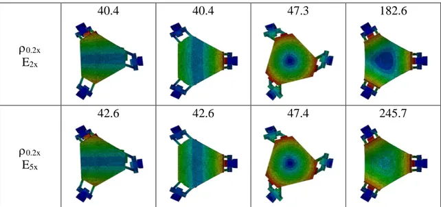
In addition to the geometrical variants operated on the platform, the following analysis is intended to address a possible change of material. Indeed, another set of FEM simulations has been carried out (results in Table 10), combining the effects of a mass reduction and a stiffness increase, so as to show which variable was going to have more influence on the bandwidth improvement. In order to easily get the point, the mass value has been cut to 50% and to 20% through a reduction in density, while the stiffness value has been magnified two and five times, acting on the elastic modulus properties, as shown in Table 9:
Mass standard [ton/mm
3]
0.5x [ton/mm3] 0.2x [ton/mm3]
2.81E-09 1.41E-09 0.56E-09
Stiffness E
standard [MPa] E2x [MPa] E5x [MPa]
69000 138000 345000
Chapter 2 Shaker bandwidth optimization
_________________________________________________________________________
28
Vibration modes - Platform material changes
Properties MODE 1 (Hz) MODE 2 (Hz) MODE 3 (Hz) MODE 4 (Hz)
standard E2x 35.7 35.7 40.0 162.4 standard E5x 37.6 37.6 40.1 210.8 0.5x Estandard 35.6 35.6 44.0 131.9 0.5x E2x 38.4 38.4 44.1 174.2 0.5x E5x 40.4 40.4 44.2 230.8 0.2x Estandard 37.5 37.5 47.2 137.5
Chapter 2 Shaker bandwidth optimization _________________________________________________________________________ 29 0.2x E2x 40.4 40.4 47.3 182.6 0.2x E5x 42.6 42.6 47.4 245.7
Table 10: Vibration modes - Platform material changes
From Table 10 arises that the same benefits on bandwidth are obtained either magnifying the stiffness or reducing the mass of the same coefficient, but leaving the other quantity to its standard value (i.e. 9% when halving the density or doubling elasticity, 14.8% when using 20% of standard density or a Young’s modulus five times greater than the standard). Instead, mixing the effects of the two quantities would lead to a significant bandwidth improvement. Therefore, a material change would be advisable, starting from a reduced density but without worsening the global stiffness of the system. From an economical point of view, the most suitable material would be the carbon woven fiber. Indeed, it shows great elastic properties in the direction normal to the in-plane texture, and a strongly reduced density with respect to aluminum. However, creating a platform with a thickness of at least 25 mm would imply many woven carbon layers, thus dramatically increasing the purchasing costs. For these reasons, an aluminum honeycomb insert would be ideal for connecting two carbon skins, saving on money and entailing a further improvement in terms of stiffness and density. Anyway, the features of the new materials will be better addressed in the next chapter.
2.3 Cubic connectors optimization
Knowing that the cubes need to host the bearings, the chance of redesign them in terms of material is strongly hindered, because of economic and technological issues. Anyway, adopting the little changes of Figure 18 (i.e. chamfering the external sides through a conventional milling process), a slight improvement would be perceived, as Table 11 shows.
Chapter 2 Shaker bandwidth optimization
_________________________________________________________________________
30
Figure 18: Chamfering of the cubes: a) Sketch; b) Cubes on platform; c) Cubes on sliders
Vibration modes - Chamfering of cubes external sides Cubes
location MODE 1 (Hz) MODE 2 (Hz) MODE 3 (Hz) MODE 4 (Hz)
On platform 34.3 34.3 41.0 129.7 On sliders 33.1 33.1 40.0 124.0 On platform and on sliders 34.3 34.3 41.2 129.7
Table 11: Vibration modes - Chamfering of cubes external sides
As inferred from Table 11, the cubes mounted on the sliders do not influence at all the bandwidth enlargement. In fact, chamfering only the cubes at the bottom of the platform, or chamfering all the six cubes of the structure, would lead to the same results, corresponding to a 4.9% bandwidth increase. Hence, the cubes located on the sliders will be left as they are.