UNIVERSITÀ DELLA CALABRIA
Dipartimento di Elettronica,
Informatica e Sistemistica
Dottorato di Ricerca in
Ingegneria dei Sistemi e Informatica
XXIII ciclo
Tesi di Dottorato
New Engine control functions for CO2 reduction
and performance improvement
DEIS- DIPARTIMENTO DI ELETTRONICA,INFORMATICA E SISTEMISTICA
Novembre
Summary
Today’s automotive market is extremely competitive and quickly changing. The customers demand excellent driving performance, new legislations impose increasingly stricter constraints and competition imposes increasingly shorter development cycles because of reduced times-to-market. Environmental awareness and public concerns about CO2 emissions have been for a long time a substantial factor in promoting technological advancements in the automotive industry. In this scenario, the actual high penetration of electronic devices in cars is and will be a key factor for the fulfillment of all the above requirements. In fact, in a recent study it has been estimated that 90% of automotive innovation includes the electrical and electronics parts.
On the other side, next generation of engines will increase in complexity, functionalities and self monitoring capabilities, with true shifts in technology, like e.g. intelligent alternators and variable valve actuation systems. In this respect, the contents of this thesis summarize my last four years of research activity which has been carried out in the field of engine control systems design and validation.
Actually, the problem of the production of polluting substances during the combustion phases depends not only by the engine structure but also on the engine management system. Therefore, the control software plays an important role in the achievement of suitable engine and vehicle performance while maintaining low emission levels. To this end, the complexity of the software functions needs to be increased, both in terms of algorithmic complexity and for the need to handle the additional degrees of freedom available (i.e. model based torque management during take off, valve timing or valve actuation management, different values for battery voltage and so on). In turn, the larger control systems complexity imposes the use of more sophisticated tools and methods for the optimization of the engine control system parameters.
Most of the work underlying this thesis has been carried out in the automotive company where I actually work for and reports the results of the many efforts accomplished in addressing such kind of problems. In particular, the research activities have been undertaken and experimented on a gasoline engine equipped with a Variable Valve Actuation (VVA) module. The potentialities of VVA systems represent the actual frontier of the engine technology and therefore such a kind of engine represents a relevant baseline for experimenting novel approaches. In particular, four main topics have been
investigated: the first one regards the design of smart alternator management algorithms that allow the achievement of lower emission levels than standard alternators and improve the performance during certain manoeuvres.
The second topic regards the development of a new method, named drive off algorithm, for handling the take off phases. This algorithm has been proved so effective in test benches that it has been implemented in all commercial vehicles since the beginning of this year. The third and fourth topics have regarded the way to manage the additional algorithmic complexity due to the availability of the further degrees offered by the new VVA technology. For this reason, a new spark advance algorithm has been developed, being the standard one not so good in adequately taking into account the specificities of the VVA technology. A second more complex aspect being addressed it has been the increased number of engine control parameters to be calibrated for this new kind of engines. The old tuning methodology based on a trial-and-error approach resulted not enough accurate for the novel control requirements and too much time-consuming. A novel tuning methodology has been developed which, on the contrary, is based on an optimization approach and allows one to achieve the desired accuracy in short times. For this reason, it has been adopted in my company since last year and it is actually used for steady state calibration of each motorization of MULTIAIR® engines.
The thesis is organized in eight chapters.
The first and second ones describe the scenario in which my work has been developed, showing the restrictive emission levels required in the automobile world and some technological enhancements for fuel economy, emission legislation fulfillment and engine performance improvements.
In the third chapter, the control algorithms developed to manage the smart alternator technology are described, showing the achieved benefits. The details of the control algorithms and the obtained results have been described in the paper (SAE2011) [12].
The fourth chapter describes the control functions used to improve the engine performance during the take off maneuver in MULTIAIR® engines. This work has been published in the paper (EAEC2011) [11].
In the fifth chapter a control function that optimizes the performance of a VVA engine has been detailed. This algorithm calculates the spark ignition timing (one of the necessary engine parameters) in order to obtain the optimal behavior in each engine working mode and in each variable valve mode. This work has been presented at the Fisita 2010 Conference (see [10]). The tools and the methodology developed for the optimization of the engine parameters have been described in another paper presented at the same conference (see [9]).
In the sixth chapter, several tools for engine control systems design and calibration have been described. This chapter contains material published in the book’s chapter [16]) and in the conference papers [71], [78], [79], [80], [81].
The seventh chapter concludes the thesis, reporting some results and showing the benefits of the proposed methodologies on a real application.
Table of contents
Summary ... 1
Table of contents... 3
List of figures... 6
Chapter 1 New automotive requirements and the role of the
Engine Control Systems ... 8
1.1 Emissions Restriction ...8
1.2 State of art foR diesel and gasoline engines ...11
1.3 Performance and robustness encreasing ...14
Chapter 2 Overview of Engine Control Systems ... 16
2.1 Variable Valve Timing System ...16
Phase Changing Systems ...16
Profile Switching Systems...18
Cam Changing and Cam Phasing Systems...19
Valve Duration Systems ...20
2.2 Variable Valve Actuation Technology ...20
The MultiAir technology ...23
2.3 Intelligent Alternator Control System ...26
Chapter 3 Control functions for CO2 reduction – Intelligent
Alternator Management ... 28
3.1 Alternator Principles...29
3.2 General description of Smart Alternator System...31
3.3 Logic Architecture...32
3.5 Experimental results and conclusions...44
Chapter 4 Control functions for performance improvement –
Drive Off Algorithm... 47
4.1 Introduction ...47
4.2 Drive off improvement reasons ...48
4.3 Vehicle equippement ...50
4.4 The drive off management algorithm ...51
4.4.1
Doma General Principles ...52
4.4.2
Recognition Of Drive Off Maneuvre...54
4.4.3
Drive Off Support Strategies ...54
4.5 Experimeental results ...58
4.6 ConclusionS...59
Chapter 5 Control function for performance improvement –
Spark Advance Algorithm ... 61
5.1 Spark advance algorithm ...61
5.2 Results and conclusionS ...65
Chapter 6 Interactive
Optimization
Methodology
and
Calibration Tools ... 67
6.1 F.I.R.E. tool Context Use ...68
Functional View ...68
Implementation View ...69
Re-usability View ...70
6.2 F.I.R.E. Tool Objectives and Main Functionalities ...70
6.3 F.I.R.E. Blockset...71
Implementation Aspects ...73
6.4 Examples of F.I.R.E. Applications ...73
6.5 Basic engine calibration objectives ...77
6.6 General purpose calibration tools ...78
Discrete regression model ...79
Discrete regression algorithm ...81
Multi Map Optimization...82
Tunable algorithms...83
6.7 Calibration performance verification tool ...84
Standard files...85
Engine bench data ...85
Calibration ...86
6.8 Developed tools: application to a real engine calibration...86
Gasoline injector model...88
6.9 Tca environment ...90
6.10 Conclusions ...92
Conclusions... 94
List of figures
Figure 1.1 EU emission standard...9
Figure 1.2 ECE/EUDC Driving Cycle, representative for EU norm. ...10
Figure 1.3 Sources of natural CO2 emissions...11
Figure 1.4 Allocation of CO2 emissions for manmade sources. ...12
Figure 1.5 Comparison between Gasoline and Diesel-Powered CO2 emissions. ...12
Figure 1.6 Emissions from Heavy-Duty Diesel and Gasoline Engines. ...13
Figure 1.7 Control system complexity...14
Figure 2.1 Cam- phasing VVT ...17
Figure 2.2 Valve Lift for an Engine with Cam Phasing VVT ...17
Figure 2.3 Valve Lift for an Engine with Cam Changing VVT ...18
Figure 2.4 Toyota’s VVTL-i system ...19
Figure 2.5 VVC system working ...20
Figure 2.6 Valve Lift for engine with VVC system...20
Figure 2.7 VVA system ...21
Figure 2.8 Valve lift profiles ...22
Figure 2.9 Solenoid valves activation and valve lift...23
Figure 2.10 Possible valve profiles using the MultiAir technology...25
Figure 3.1 Alternator circuit. ...29
Figure 3.2 Thee-phase bridge. ...29
Figure 3.3 Alternator characteristic at E and N constant. ...31
Figure 3.4 Logic Architecture Scheme ...32
Figure 3.5 State flow diagram of Smart Alternator Management...35
Figure 3.6 Voltage Battery Control Scheme in PB, RB, QC IAM status ...35
Figure 3.7 Alternator feature scheme. ...36
Figure 3.8 Generic PID scheme...37
Figure 3.9 First Alternator Control algorithm scheme...38
Figure 3.10 Second Alternator Control Algorithm scheme ...39
Figure 3.11 Third Alternator Control Algorithm scheme ...41
Figure 3.12 Third Alternator Control Algorithm Simulink scheme ...42
Figure 3.13 Voltage Variation function ...43
Figure 3.15 Extra-urban cycle example on TwinAir gasoline engine ...46
Figure 4.1 Example of drive off manoeuvre...49
Figure 4.2 Vehicle interface configuration. ...50
Figure 4.3 Completely pressed pedal clutch configuration...51
Figure 4.4 Example of engine maximum performance curve...55
Figure 4.5 DoMA ignition timing management ...57
Figure 4.6 DoMA working scheme ...58
Figure 4.7 Comparison of manoeuvres with and without the DoMa algorithm. ...59
Figure 5.1 Spark Advance algorithm maps. ...61
Figure 5.2 Torque interface. ...62
Figure 5.3 Advance vs Manifold Pressure at Rpm fixed for different air inlet load...63
Figure 5.4 Spark advance algorithm. ...64
Figure 5.5 Max Angle Ref for EIVC and LIVO mode. ...65
Figure 5.6 The spark advance algorithm tuning. ...65
Figure 5.7 Graphic of predicted vs observed. ...66
Figure 5.8 Spark Advance algorithm error distribution...66
Figure 6.1 Functional view ...69
Figure 6.2 Implementation view...70
Figure 6.3 Re-usability view ...70
Figure 6.4 Building a new F.I.R.E. model ...72
Figure 6.5 MaskSubsystem_template block. ...73
Figure 6.6 Different time slicing on a control system. ...74
Figure 6.7 Air Conditioner Test with ECU’s functional view ...75
Figure 6.8 Air Conditioner Test with ECU’s implementation view ...76
Figure 6.9 Air Conditioner Test with ECU’s implementation view with a new task allocation ...77
Figure 6.10 Multivariable switching regression model example ...79
Figure 6.11 Discrete Regression tool example ...80
Figure 6.12 DiscreteRegression explanation ...81
Figure 6.13 Multi map optimization working scheme...82
Figure 6.14 Multimap optimization example ...83
Figure 6.15 Torque interface verification tool...85
Figure 6.16 Charge estimation calibration verification tool. Inlet efficiency curves depending on cam phaser position, at defined intake manifold pressures ...87
Figure 6.17 Air charge estimation calibration verification tool. Total performance, statistics...88
Figure 6.18 Torque verification tool, cam phaser position dependency ...90
Chapter 1
New automotive requirements and
the role of the Engine Control Systems
The automotive industry is facing a very challenging phase. The coming scenario consists of more and more ambitious requirements regarding fuel consumption, fun to drive and also important constraints due to new emissions legislation:
• Euro 5+ for additional diagnostic requirements
• Euro 6 for challenging emission levels
which are going to be mandatory for every new vehicle homologation starting from September 2011 and for every vehicle registration from January 2014.
The most part of these new requirements are principally affecting the powertrain with additional mechanical subsystems and related pieces of electronics to manage them. Consequently, the engine control systems necessarily will become more complex, for the need to manage additional functionalities and govern the cooperation between the new and the old technologies. Also, they will have to maintain back compatibility with the old engines guaranteeing in any case the best possible performance.
1111....1111EMISSIONS RESTRICTIOEMISSIONS RESTRICTION EMISSIONS RESTRICTIOEMISSIONS RESTRICTION N N
The regulation norms on emissions for the automotive industry were introduced first in the United States in the sixties, when the growing amount of vehicles started to increase the atmospheric pollution, producing effects on people health. For this reason, the USA authorities began to emit specific legislations in order to regulate the vehicle emissions. After that, during the seventies, also the Europe defined first laws on pollution emissions. European Union emission regulations for new light duty vehicles (passenger cars and light commercial vehicles) were once specified in the Directive 70/220/EEC with a number of amendments adopted through 2004. In 2007, this Directive has been repealed and replaced by the Regulation 715/2007 (Euro 5/6). Some of the important regulatory steps implementing emission standard for light-duty vehicles were:
• Euro 1 standards (also known as EC 93): Directives 91/441/EEC (passenger cars only) or 93/59/EEC (passenger cars and light trucks), approved in July of 1992.
• Euro 2 standards (EC 96): Directives 94/12/EC or 96/69/EC, approved in January of 1996.
• Euro 3/4 standards (2000/2005): Directive 98/69/EC, further amendments in 2002/80/EC, Euro 3 was approved in January of 2000, Euro 4 in January of 2005 for the vehicle homologation, in January of 2006 for the vehicle registration.
• Euro 5/6 standards (2009/2014): Regulation 715/2007 (“political” legislation) and Regulation 692/2008 (“implementing” legislation) The emission standards for light-duty vehicles are applicable to all vehicles of categories M1, M2, N1 and N2, with a reference mass not exceeding 2610 kg (Euro 5/6). EU regulations introduce different emission limits for compression ignition (diesel) and positive ignition (gasoline, NG, LPG, ethanol) vehicles. Diesels have more stringent CO standards but are allowed higher NOx. Positive ignition vehicles were exempted from PM standards through the Euro 4 stage. Euro 5/6 regulations introduce PM mass emission standards, equal to those for diesels, for positive ignition vehicles with DI engines.
The 2000/2005 standards were accompanied by an introduction of more stringent fuel regulations that require minimum diesel cetane number of 51 (year 2000), maximum diesel sulfur content of 350 ppm in 2000 and 50 ppm in 2005, and maximum petrol (gasoline) sulfur content of 150 ppm in 2000 and 50 ppm in 2005. “Sulfur-free” diesel and gasoline fuels (≤ 10 ppm S) must be available from 2005, and became mandatory from 2009.
EU emission standards are summarized in the table 1.1. All dates listed in the table refer to new type approvals. The EC Directives also specify a second date, one year later, unless indicated otherwise, which applies to first registration (entry into service) of existing, previously type-approved vehicle models.
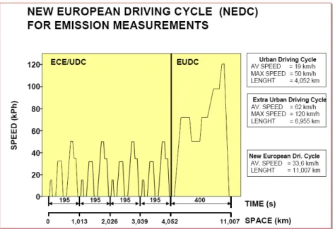
In order to measure the emission index, the vehicle has to cover a real representative driving cycle that covers idle conditions, low and high constant speed, acceleration and deceleration, urban and extra-urban driving cycles. Effective after year 2000 (Euro 3), that test procedure was modified to eliminate the 40 s engine warm-up period before the beginning of emission sampling. This modified cold start test is referred to as the New European Driving Cycle (NEDC) or as the MVEG-B test. All emissions are expressed in g/km.
The Euro 5/6 implementing legislation introduces a new PM mass emission measurement method (similar to the US 2007 procedure) developed by the UN/ECE Particulate Measurement Programme (PMP) and adjusts the PM mass emission limits to account for differences in results using the old and the new method. The Euro 5/6 legislation also introduces a particle number (PN) emission limit in addition to the mass-based limits.
In Figure 1.2 the “New European Driving Cycle” NEDC is reported, composed by the ECE cycle, which represents a typical urban driving cycle and it is considered for four times, and by the EUDC cycle, which represents a typical extra urban driving cycle, where the vehicle runs up to 120 km/h.
Figure 1.2ECE/EUDC Driving Cycle, representative for EU norm.
During the cycle, the exhaust gas are sampled, the pollulants species are individuate and compared with the target thresholds.
Starting from the Euro 3 stage, vehicles must be equipped with an onboard diagnostic system for emission control. Driver must be notified in the case which a malfunction or deterioration of the emission system occurs that would
cause emissions to exceed mandatory thresholds. The thresholds are based on the NEDC (cold start ECE+EUDC) test. To distinguish from the US OBD, the European limits are also referred to as the EOBD (European OBD).
1111....2222STATE OF ART STATE OF ART STATE OF ART STATE OF ART FORFORFORFOR DIESEL AND GASOLINE DIESEL AND GASOLINE DIESEL AND GASOLINE ENGINES DIESEL AND GASOLINE ENGINES ENGINES ENGINES
Besides their fuel economy advantage, the diesel engines emit extremely low concentrations of unburned hydrocarbons and carbon monoxide emissions [8].
The reason for these extremely low hydrocarbon (HC) and carbon monoxide (CO) emissions is that diesels operate in very lean regimes where λ (relative air/fuel ratio) is greater than 1 [1].Carbon dioxide (CO2) is the major product generated in the combustion of fossil fuels. This exhaust species is generally referred to as a greenhouse gas and considered responsible for global warming.
In spite of this belief, CO2 remains an unregulated emission species. However, at recent environmental world meetings where concerns over the global effects of emissions were discussed, new commitments were made to collectively work at reducing CO2 emissions. Interestingly, CO2 emissions produced by natural phenomena far exceed those which are manmade. Figure 1.3 shows the apportionment of CO2 emission from natural sources [8]. The total yearly CO2 emissions from natural sources is estimated at 770×109 tons/annum. By contrast, the total yearly manmade CO2 emissions is estimated at 26×109 tons/annum, less than 4% of the total CO2 inventory.
Figure 1.3Sources of natural CO2 emissions
Even though manmade CO2 emissions may represent a small percentage of the global CO2 problem, it is important that actions are taken to minimize its impact on the environment. Figure 1.4 gives the CO2 allocation of each manmade source [8]. Power generation, heating, and industrial activities are responsible for about 70% of manmade CO2, while transportation-related CO2 represents about 16% of all manmade CO2.
Figure 1.4Allocation of CO2 emissions for manmade sources.
With the worldwide predominance of gasoline-powered personal transportation, conversion to modern diesel-powered vehicle could reduce transportation-related CO2 by about 25% from current levels. Figure 1.5 represents the results obtained by the German Federal Environmental Agency on 99 gasoline- and 36 diesel-powered vehicles in 1991 [8]. From that study, it was concluded that diesels had an average of 19% advantage over gasoline engines, in CO2 emission. The diesel engines involved in that study were mostly indirect-injected engines that are lower in fuel efficiency than their direct-injected counterparts by about 10 to 15%.
Hence a 25% reduction in transportation-related CO2 emissions by encouraging dieselization of gasoline-powered vehicles is thought to be quite feasible.
While diesel engines are known for their high engine-out emission of nitrogen oxides, the NOx issue is perhaps worth further examination to put matters in their proper perspective. A sample of about 15 heavy-duty gasoline engines calibrated to meet the 1991 US Federal emission standards were tested according to EPA specifications. The mathematical average of their emissions is given in Table 1, where the corresponding results of a statistically representative sample of diesel engines of the same capacity are included. In addition, a line of emission data obtained by testing the same heavy-duty gasoline engine when equipped with a 3-way catalyst is also provided in Figure 1.6, for comparative purposes.
Figure 1.6Emissions from Heavy-Duty Diesel and Gasoline Engines.
In diesel engines both HC and CO emissions are a small fraction of those found in their gasoline engine-out counterparts. Even diesel engine-out NOx emissions, in the example of Figure 1.6, are almost 1.0 g/bhp-hr less than their corresponding gasoline emissions. However, thanks to the 3-way catalyst conversion efficiency, the same gasoline engines emit extremely low HC, CO, and NOx emissions. Of course, conditions in the exhaust have to be conducive to the optimum operation of the 3-way catalyst. With accurate control of the fuel and air, modern gasoline engines operate at stoichiometric ratio where the catalyst performs at its highest conversion efficiency. Unfortunately, diesel exhaust is extremely lean and reducing NOx in an oxygen-rich environment is a very challenging task. The catalyst industry is developing solutions for the diesel NOx problem, but so far there is a lot of debate regarding the most plausible method of dealing with this problem.
Another problematic pollutant associated with diesel engines is particulate matter. The casual observer is made aware of this pollutant in the form of black smoke or soot emitted from either the tail pipes of many diesel-equipped passenger cars or the stacks of diesel-powered heavy-duty vehicles. Emission of soot is also accompanied with other matter suspended in the exhaust, such as: unburned lube oil, unburned fuel, trace metals, and sulfur byproducts.
Emission of soot in particulate matter results from the nature of the heterogeneous combustion process or diffusion type combustion that is prevalent in diesel engines. Fuel and air mixture preparation in modern diesel engines has greatly reduced this problem. In addition, the development of diesel particulate filters promises to eliminate it altogether. Particulate matter is not yet regulated in gasoline engines.
Due to the wedlock explained before, joining with the overall constraints necessary to optimize a vehicle; as consumption reduction and performance increasing, the old engine management techniques isn’t enough to fulfill all these demands.
In Figure 1.7 the complexity of control system has been expressed in terms of new components and number of control parameters (to be calibrated).
Figure 1.7Control system complexity
Because of competition, time to market is more and more reducing and consequently the development time is becoming shorter and shorter: for instance only 18 months are allowed for the development of new engine and related control system while that time was of 25 months only few years ago.
The peculiarity of automotive industry, consisting of large scale production, makes it a risky business because a single problem can affect thousands and sometimes millions of models: there is less time to develop the system but no errors are admitted. Several cases regarding recall campaigns have been published also for the most important carmakers. In this situation, being able to meet requirements and guarantee the necessary quality level (Index Per Thousand Vehicles indicators are used to define the expected level of quality: some units are the current targets) is really a challenge if an effective, predictable and fast development process is not available.
1111....3333PERFORMANCE AND ROBUPERFORMANCE AND ROBUPERFORMANCE AND ROBUPERFORMANCE AND ROBUSTNESS ENCREASINSTNESS ENCREASINSTNESS ENCREASINGGGG STNESS ENCREASIN
The automotive industry is one of the most competitive markets in terms of performance and cost. Obviously clients will have to pay an increased number of mechanical failures and driving feelings from reducing the development and producing costs. These issues lead many journalists to criticize new models by
doing benchmarks and product tests. A negative feedback can create problems in the market, reducing the amount of vehicles sold and therefore the profit.
OEMs are always searching for innovative solutions that can give them market advantages:
• on gasoline engines, the need of responsiveness and fuel consumption reduction brought to the introduction of the MULTI-AIR® technology that manages in a flexible way the air intake valves;
• to reduce noise and vibration harshness (NVH) at the stop light or in traffic queues, Start & Stop technology, that switches off the engine automatically at each vehicle stop, are being deployed;
• to improve fun to drive and once again to reduce fuel consumption, smart management of the alternator has been developed; it manages the battery charge in braking and acceleration phases;
• emission reduction on diesel engines, has been achieved with a flexible fuel injection management on common rail systems, so called MULTI-JET II®, up to 10 injections per engine cycle;
• to improve driving comfort and safety, Hill Holder technology, that brakes the vehicle automatically in a drive off on a slope to prevent vehicle roll-back;
• to improve the drive off maneuver the analogic clutch and the accelerometer sensor are employed.
These complex electronics peculiarities are also necessary for low-segment vehicles. Therefore, the electronic components are increasing, such as the degrees of freedom.
Each new technology introduced cannot be seen as a component that is simply added to the vehicle but must be managed by algorithms in charge to coordinate all present features with the added ones. Because the increase of complexity is exponential, it is very difficult to foresee the complete interaction of each technology with the risk of delivering products with lacks of performance.
Chapter 2
Overview of Engine Control
Systems
The recent trend in engines design is the use of low displacement engines (the so called “downsizing”) to fulfill the new requirements. The need for torque and power increments is obviously in contrast with fuel consumption reduction. Therefore, new technologies need to be used in order to induce different engine working conditions. On gasoline engine the industrial research is focused on the development of a new way to let the air enter into the engine: the Variable Valve Timing, or Variable Valve Actuation system (and also the use of Turbo Charger) have the objective to minimize the power required for pumping the air in the cylinders and, in turn, maximize the engine efficiency. In this scenario a revolutionary approach has been introduced by Fiat by means of the MultiAir technology, detailed in this chapter, that permits to define the desired inlet valve timing.
2222....1111VARIABLE VVARIABLE VALVE TIVARIABLE VVARIABLE VALVE TIALVE TIMING SYSTEMALVE TIMING SYSTEMMING SYSTEMMING SYSTEM
In traditional internal combustion engines (ICE), gas exchange valve timing is mechanically fixed with respect to the crankshaft position. This timing determines when the valves open and close, thereby affecting the air-fuel mixture and exhaust flow.
Variable Valve Timing (VVT) is a generic term for various concepts that allow one to change the advance, overlap, and even (in the case of some overhead-cam engines) the duration and lift of a four-stroke internal-combustion engine's intake and exhaust valves while the engine is operating. This technology has been under development for more than a century (a variation was tried out on some early steam engines), but it is only within the last twenty years or so with the advent of sophisticated electronic sensors and engine management systems that it has become practical and effective. There are a number of different variable valve timing systems, currently available and under development, to control the different valve timing parameters. These systems can be grouped in terms of their operations as:
• Phase Changing Systems
• Profile Switching Systems
• Cam Changing and Cam Phasing Systems
• Valve Duration Systems Phase Changing Systems
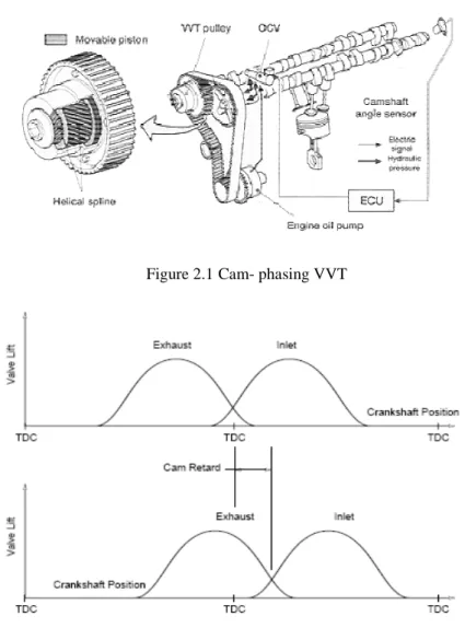
Examples of cam-phasing VVT are:
• Toyota’s VVT-i (Variable Valve Timing with Intelligence), which intelligently adjusts the overlap time between the exhaust valve closing and the intake valve opening;
• Lexus’s VVT-iE (VVT – intelligent by Electric motor), which consists of the cam phase converter, mounted on the intake camshaft which converts the motor rotational input into the advance and retard of the cam phase, and a brushless electric motor, installed in the engine chain case.
Figure 2.1Cam- phasing VVT
Figure 2.2Valve Lift for an Engine with Cam Phasing VVT
Phase changing systems have been available on production engines for a number of years but have tended to be applied only to the highest specification engines of a particular range. Phasing the intake camshaft to gain increased performance, with a mechanism that can be moved between two fixed camshaft timings, is the most common application with the change in timing normally
occurring at a particular engine speed. More recently, there has been a move towards more flexible control systems that allow the camshaft phasing to be maintained at any point between two fixed limits. This has facilitated camshaft phase optimization for different engine speed and load conditions and has allowed exhaust camshaft phasing to be used for internal EGR control.
Profile Switching Systems
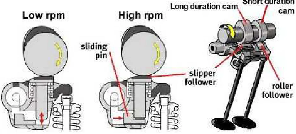
This type of variable valve timing system is capable of independently changing the valve event timing and the valve peak lift. The system switches between two different camshaft profiles on either or both of the camshafts and is normally designed to change at a particular engine speed (Figure 2.3). One profile designed to operate the valves at low engine speeds provides good road manners, low fuel consumption and low emissions output. The second profile is comparable to the profile of a race cam and comes into operation at high engine speeds to provide a large increase of power output. Therefore, cam- changing VVT systems act as if two different cam types at high and low speed were used.
Figure 2.3Valve Lift for an Engine with Cam Changing VVT Honda, with the VTEC (Variable Valve Timing and Electronic Lift Control) system started production of a system that gives an engine the ability to operate on two completely different cam profiles, eliminating a major compromise in the engine design. In its simplest form, VTEC allows the valves to remain open for two different durations: a short opening time for low-speed operations to give good torque and acceleration, and a larger opening time at higher speeds to give more power. For accomplishing that, the camshaft has two sets of cam lobes for each valve and a sliding locking pin on the cam follower that determines which lobe is operating the valve. The locking pin is moved by a hydraulic control valve based on the engine speed and power delivery requirements. The two lobe shapes are referred to as fuel economy cams and high power cams, meaning that Honda engines with this technology are really two engines in one - a performance engine and an economical engine.
Because these systems have inherently two-position operations, they are not suitable for being optimized under different load conditions, e.g. EGR control. The ability to change the valve event timing, the lift and duration ensures that
these systems are capable of providing very high power output from a given engine whilst still complying with the emissions legislation.
Cam Changing and Cam Phasing Systems
By combining cam-changing VVT and cam-phasing VVT, one could satisfy the requirement of both top-end power and flexibility throughout the whole rev range, but it is inevitably more complex.
A typical example of this system is the Toyota’s VVTL-i (Figure 2.4). The system can be seen as a combination of the existing VVT-i and Honda’s VTEC, although the mechanism for the variable lift is different from Honda. Like VVT-i, the variable valve timing is implemented by shifting the phase angle of the whole camshaft forward or in reverse by means of a hydraulic actuator attached to the end of the camshaft. Like VTEC, Toyota’s system uses a single rocker arm follower to actuate both intake valves (or exhaust valves). It also has two cam lobes acting on that rocker arm follower, the lobes have a different profile - one with longer valve-opening duration profile (for high speed), another with shorter valve-opening duration profile (for low speed). At low speed, the slow cam actuates the rocker arm follower via a roller bearing (to reduce friction). The high speed cam have not any effect on the rocker follower because there is sufficient spacing underneath its hydraulic tappet. At low speeds, the long duration cam idles while when the speed has increased to the threshold point, the sliding pin is pushed by hydraulic pressure to fill the spacing. The high speed cam becomes effective. Note that the fast cam provides a longer valve-opening duration while the sliding pin adds valve lift (while for Honda VTEC, both the duration and lift are implemented by the cam lobes). VVTL-i offers variable lift, which lifts its high speed power output a lot. Compared to Honda VTEC, Toyota’s system has continuously variable valve timing which helps it to better achieve low to medium speed flexibility. Therefore, it is undoubtedly the best commercial VVT system today available. However, it is also more complex and probably more expensive to build.
Valve Duration Systems
The basic concept of this system is that of lengthening the duration of the opening of the valves. This system was introduced by Rover who call it Variable Valve Control (VVC). The VVC principle is based on an eccentric rotating disc to drive the inlet valves of every two cylinders. Since the eccentric shape creates nonlinear rotation, the opening period of the valves can be varied by controlling the eccentric position of the disc. With VVC the outlet camshaft is not part of the VVC system and is driven normally by the toothed belt from the crankshaft. Figure 2.5 shows an example of a working VVC system. When the eccentric wheel, which is connected to crankshaft with revolution speed halved, rotates at 180°, the camshaft turns, for example, only 140°. In the following 180° of eccentric wheel, the camshaft turns instead 220° so that it remains totally in phase with the crankshaft. This variable camshaft speed can change the duration of inlet valves opening. Figure 2.6 shows the valve lift for an engine with VCC Rover.
Figure 2.5VVC system working
Figure 2.6Valve Lift for engine with VVC system 2222....2222VARIABLE VALVE AVARIABLE VALVE AVARIABLE VALVE AVARIABLE VALVE ACTUATION CTUATION CTUATION CTUATION TECHNOLOGYTECHNOLOGYTECHNOLOGYTECHNOLOGY
The Variable Valve Actuation technology represents the new timing system with variable lift of the intake valves that has been developed in recent years. The VVA has been introduced as a promising technology able to improve the performance of the vehicle in terms of fuel economy, emission reductions and, more generally, the whole efficiency of the system. Contrary to classical engines, where the intake and exhaust valves are commanded mechanically by
the camshaft and so both the timing and the duration of valves opening are fixed by events, the VVA system offers the possibility to vary the valves actuation. Moreover, the innovative VVA system allows one to control the air mass flow rate that is inducted in an internal combustion engine without any use of the throttle plate; this last situation has the benefit of having an air pressure upstream of intake valves always constant because the pump losses near the throttle body are zero.
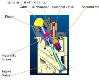
The adopted VVA system is shown schematically in Figure 2.7. The valve actuator consists of a piston connected through an oil chamber to the intake valve, a solenoid valve to regulate the pressure inside the oil chamber and a hydraulic brake to assure the soft landing. When the electro-valve is open, the oil comes out from the high pressure chamber and it can be consequently possible to obtain any condition included between the two following extreme modalities:
• if the solenoid valve is open the intake valves remain closed;
• if the solenoid valve is always closed, the lift of the valves is the same as that of the cams.
Figure 2.7VVA system
As reported in Figure 2.8, the valve lift profile can assume different forms depending on the required air mass flow rate and engine speed. In fact, with this particular VVA system many strategies are possible, such as those indicated in the following points:
• Full Lift (FL) actuation mode represents the normal functioning of the valves, i.e. commanded mechanically by the camshaft: the solenoid valve remains closed assuring high pressure into the oil chamber and, consequently, assuring a rigid connection between the intake valve and the camshaft through the piston;
• Early Closure (EC) valve mode is obtained by opening the solenoid valve at a certain cam angle, i.e. the control angle, reducing the pressure inside the oil chamber. The motion of the intake valve is then decoupled from the piston and, forced by the valve springs. It starts to close earlier than in the full-lift mode. Soft landing of the intake valve is controlled by a hydraulic dampening unit (hydraulic brake);
• Late Opening (LO) valve mode can be achieved by regulating the solenoid valve partially opened. In this way, the pressure inside the oil chamber is regulated to a lower pressure than in the full lift mode, obtaining a rigid connection, but with a shorter distance function of the chamber pressure, between the intake valve and the camshaft. Consequently, the valve profile is similar to the full lift mode, but with a smaller time duration;
• Multi Lift (ML) actuation mode is a particular operative actuation mode obtained combining the late opening with the early closure, as is shown in Figure 2.9 This profile is limited by the mechanical cam constrains, in fact the next late opening must be activate before 50% of the full lift cam.
The flexibility of the intake valve control offered by the VVA system leads to enhancing the efficiency of the combustion process. More in general, the following advantages can be addressed by the introduction in the vehicle of the VVA system:
• high charge trapping efficiency over the entire speed range through a wide modulation of valve lift;
• throttle-less engine operation, through direct air control at the valves resulting in a reduction of pumping work and fuel consumption;
• dynamic control, cylinder by cylinder and stroke by stroke, of the inlet charge aimed at an improvement of emissions, drivability and fuel consumption in transient operation.
Figure 2.9Solenoid valves activation and valve lift
The electro-hydraulic actuator that has been developed is relatively simple and behaves high hardiness characteristics and low sensitivity to critical parameters, like variation of the oil viscosity related to temperature.
Finally, the control of this innovative VVA system is achieved by a specific electronic control system that contains model-based strategies allowing the elaboration of the valve actuation signals according to the demands of the driver [5].
The MultiAir technology developed by Fiat is an example of application of Variable Valve Actuation system.
The MultiAir technology
In the last decade, the development of the Common Rail technology for Diesel engines marked a breakthrough in the passenger car market. To be competitive also in the field of gasoline engines, Fiat Group decided to follow the same approach and focus on breakthrough technologies. The aim was to provide customers with substantial benefits in terms of fuel economy and fun-to- drive while maintaining the engine intrinsic comfort characteristics, based on a smooth combustion process and on light structures and components.
The key parameter to control Diesel engine combustion and therefore performance, emissions and fuel consumption is the quantity and characteristics of the fuel injected into cylinders. That is the reason why the Common Rail electronic Diesel fuel injection system was such a fundamental breakthrough in Direct Injection Diesel engine technology. The key parameter to control gasoline engine combustion, and therefore performance, emissions and fuel consumption, is the quantity and characteristics of the fresh air charge in the cylinders. In conventional gasoline engines the air mass trapped in the cylinders is controlled by keeping the intake valves opening constantly and adjusting upstream pressure through a throttle valve. One of the drawbacks of this simple conventional mechanical control is that the engine wastes about 10% of the input energy in pumping the air charge from a lower intake pressure to the atmospheric exhaust pressure.
A fundamental breakthrough in air mass control, and therefore in gasoline engine technology, is based on direct air charge metering at the cylinder inlet ports by means of an advanced electronic actuation and control of the intake valves, while maintaining a constant natural upstream pressure.
Research on this key technology started in the eighties, when engine electronic control technologies reached the stage of mature technologies. At the
beginning world-wide research efforts were focused on the electromagnetic actuation concept, following which valve opening and closing is obtained by alternatively energizing upper and lower magnets with an armature connected to the valve. This actuating principle had the intrinsic appeal of maximum flexibility and dynamic response in valve control, but despite a decade of significant development efforts the main drawbacks of the concept (its being intrinsically not fail-safe and its high energy absorption) could not be fully overcome. At this point most automotive companies fell back on the development of the simpler, robust and well-known electromechanical concepts, based on the valve lift variation through dedicated mechanisms, usually combined with cam phasers to allow control of both valve lift and phase. The main limitation of these systems is low flexibility in valve opening schedules and a much lower dynamic response; for example, all the cylinders of an engine bank are actuated simultaneously, thereby excluding any cylinder selective actions. Many similar electromechanical valve control systems were then introduced over the past decade.
In the mid 90’s Fiat Group research efforts switched to electro-hydraulic actuation, leveraging on the know-how gained during the Common Rail development.
The goal was to reach the desired flexibility of valve opening schedule air mass control on a cylinder-by-cylinder and stroke-by-stroke basis. The electro-hydraulic variable valve actuation technology developed by Fiat was selected for its relative simplicity, low power requirements, intrinsic fail safe nature and low cost potential.
The operating principle of the system, applied to intake valves, is the following: a piston, moved by a mechanical intake cam, is connected to the intake valve through a hydraulic chamber, which is controlled by a normally open on/off solenoid valve.
When the solenoid valve is closed, the oil in the hydraulic chamber behaves like a solid body and transmits to the intake valves the lift schedule imposed by the mechanical intake cam. When the solenoid valve is open, the hydraulic chamber and the intake valves are de-coupled; the intake valves do not follow the intake cam anymore and close under the valve spring action. The final part of the valve closing stroke is controlled by a dedicated hydraulic brake, to ensure a soft and regular landing phase in any engine operating conditions.
Through solenoid valve opening and closing time control, a wide range of optimum intake valve opening schedules can be easily obtained.
For maximum power, the solenoid valve is always closed and full valve opening is achieved completely following the mechanical cam (Full Lift mode), which was specifically designed to maximize power at high engine speed (long closing time). For low-rpm torque, the solenoid valve is opened near the end of the cam profile, leading to early intake valve closing (EIVC mode). This eliminates unwanted backflow into the manifold and maximizes the air mass trapped in the cylinders. In engine part load, the solenoid valve is opened earlier (before finishing of the cam profile) causing partial valve openings to control the trapped air mass as a function of the required torque (Partial Load mode). Alternatively the intake valves can be partially opened by closing the solenoid
valve once the mechanical cam action has already started (LIVO mode: Late Intake Valve Opening). In this case the air stream into the cylinder is faster and results in higher in-cylinder turbulence. The last two actuation modes can be combined in the same intake stroke, generating a so-called “Multilift” mode, which enhances turbulence and combustion rate at very low loads. Figure 2.10 shows possible valve profiles using the multi-air technology.
Figure 2.10Possible valve profiles using the MultiAir technology The Multiair Technology potential benefits for gasoline engines exploited so far can be summarized as follows:
• Maximum Power is increased by up to 10% thanks to the adoption of a power-oriented mechanical cam profile;
• Low-rpm Torque is improved by up to 15% through early intake valve closing strategies that maximize the air mass trapped in the cylinders;
• Elimination of pumping losses brings a 10% reduction of fuel consumption and CO2 emissions, both in naturally aspirated and turbocharged engines with the same displacement;
• MultiAir turbocharged and downsized engines can achieve up to 25% fuel economy improvement over conventional naturally aspirated engines with the same level of performance;
• Optimum valve control strategies during engine warm-up and internal Exhaust Gas Recirculation, realized by reopening the intake valves during the exhaust stroke, result in emissions reduction ranging from 40% for HC/CO to 60%for NOx;
• Constant upstream air pressure, atmospheric for naturally aspirated and higher for turbocharged engines, together with the extremely fast air mass control, cylinder-by-cylinder and stroke-by-stroke, result in a superior dynamic engine response.
The MultiAir technology, a Fiat worldwide premiere in 2009, has introduced further technological evolutions for gasoline engines:
• Integration of the MultiAir direct air mass control with direct gasoline injection to further improve transient response and fuel economy;
• Introduction of more advanced multiple valve opening strategies to further reduce emissions;
• Innovative engine-turbocharger matching to control trapped air mass through combination of optimum boost pressure and valve opening strategies.
While electronic gasoline fuel injection developed in the ‘70s and Common Rail developed in the ‘90s were fuel specific breakthrough technologies, the MultiAir Electronic Valve Control technology can be applied to all internal combustion engines whatever fuel they burn.
MultiAir, initially developed for spark ignition engines burning light fuel ranging from gasoline to natural gas and hydrogen, has wide potential also for Diesel engine emissions reduction. Intrinsic NOx reduction of up to 60% can be obtained by internal Exhaust Gas Recirculation (iEGR) realized with intake valves reopening during the exhaust stroke, while optimal valve control strategies during cold start and warm-up bring up to 40% HC and CO reduction of emissions. Further substantial reduction comes from the more efficient management and regeneration of the diesel particulate filter and NOx storage catalyst, thanks to the highly dynamic air mass flow control during transient engine operation.
Diesel engine performance improvement is similar to that of the gasoline engine and is based on the same physical principles. Instead, fuel consumption benefits are limited to few percentage points because of the low pumping losses of Diesel engines, one of the reasons of their superior fuel economy. In the future, power train technical evolution might benefit from a progressive unification of gasoline and Diesel engines architectures.
A MultiAir engine cylinder head can therefore be conceived and developed, where both combustion systems can be fully optimized without compromises. Moreover the MultiAir electro-hydraulic actuator is physically the same, with minor machining differences, while internal subcomponents are all carry over from the Fire and SGE (small gasoline engine) applications [6], [7].
2222....3333INTELLIGENT ALTERNATINTELLIGENT ALTERNATINTELLIGENT ALTERNATINTELLIGENT ALTERNATOR CONTROL SOR CONTROL SOR CONTROL SOR CONTROL SYSTEMYSTEMYSTEMYSTEM
An alternator is an electromechanical device that converts kinetic energy into electrical energy and is used in modern automobiles to charge the battery and to power a car's electric system when its engine is running. It is connected to the engine via a belt that transmits the motion of rotation that within the alternator is used to produce alternating electric current (AC). Automotive alternators use a set of diodes to convert AC to DC (direct current). A voltage regulator makes for the voltage output from the alternator to remain constant.
Intelligent Alternator Control System (IAC) allows some energy to recover, through "intelligent" use of the alternator, which during braking is dissipated as heat in brake discs. The IAC system generates electric power for a car’s on board network exclusively in over-run and during braking to transform the
kinetic energy resulting from the inertia of the vehicle into electrical energy that is transferred to the battery becoming an energy surplus, which can return available in the following phases of acceleration when it is used to feed the electrical components of the vehicle, thus decreasing the work required at the alternator at this stage. This results in more torque being produced and delivered to the wheels. Normally, the engine control system determines the power that is used to activate the alternator --through a torque-based model.
The IAC system establishes that:
• in theacceleration phase, the alternator output voltage is set so that it is equal or close to the level of battery voltage, which, in this way, provides alone for the electricity needs of the car;
• in over-run or during breaking, the alternator output voltage is set to a value higher than the battery voltage, so the alternator is not only able to cover the entire electricity demand of the vehicle, but at the same time to charge the battery.
In the latter case, the alternator is actually a load on the crankshaft and thereby exerts a braking effect on the vehicle which represents precisely the recovery of part of the energy dissipated in the brakes. For the IAC system it’s necessary to have precise information about the charging status and battery usage which are acquired by using a sensor IBS (Intelligent Battery Sensor). The battery is charged to only about 80% of its capacity as long as the engine is propelling the car, depending on ambient conditions. A reserve charge that is adequate for the consumption of power while the car is at a standstill and enabling the driver to start at any time, is maintained under all circumstances. Battery charge exceeding the 80% threshold is generated only in over-run and while the driver is applying the brakes. Since the number of charge cycles increases as a function of such battery management, IAC uses modern AGM (absorbent glass mat) batteries able to handle greater loads than conventional lead acid batteries.
The IAC system improves the overall efficiency of a vehicle by decreasing ancillary loads on the engine and by recuperating more of the waste heat energy so as to reduce fuel consumption.
Chapter 3
Control functions for CO2 reduction
– Intelligent Alternator Management
In modern internal combustion engines a greater reduction of CO2 emissions
is required in order to significantly reduce fuel consumption and minimize the emissions of polluting gases, allowing them to fall within the strict limits set by current regulations. In a conventional engine control system, it is not possible to optimize the efficiency of the alternator in terms of emissions and fuel consumption, due to a constant voltage which is imposed and is not modifiable. On the contrary, in a system capable of controlling the voltage of the alternator, referring to such an alternator as “smart” hereafter, it would be possible to optimize its efficiency as a function of the vehicle/engine working points. This system requires first and foremost a communication protocol between the alternator and engine control unit, and a special sensor that gets data on the charging status of the battery.
In this chapter a management strategy is proposed for regulating the alternator regulation voltage in order to maximize its efficiency on the basis of the engine and vehicle conditions. This is done by using an “Intelligent Alternator Module (IAM)”, that communicates using the LIN protocol with the Engine Control Module (ECM), and an “Intelligent Battery Sensor (IBS)”, which provides the information about the battery State-Of-Charge (SOC).
The main features of the management strategy are:
• switch off the alternator during tip-in manoeuvres in order to maximize the performance;
• switch off the alternator when the catalyst is cold, so as to reduce the emissions, and in idle conditions if the battery SOC is high enough;
• increase the alternator load during tip-out manoeuvres, braking or cut-offs, and during shut-down in order to recover the kinetic energy otherwise dissipated as heat in the brakes;
• control the alternator voltage regulation in steady-state as a function of battery SOC, loading it only when needed.
These procedures are implemented for both Gasoline and Diesel Engines and several improvements result: the average life of the vehicle battery has been increased and fuel consumption and emission have been reduced. In particular, measurements done have shown that consumption reduction due to the control system described above is about 2-3% on the NEDC homologation cycle.
3333....1111ALTERNATOR PRINCIPLEALTERNATOR PRINCIPLEALTERNATOR PRINCIPLEALTERNATOR PRINCIPLESSSS
In Figure 3.1 the mono-phase equivalent circuit of the alternator is reported in order to better shows the voltage and the current under analysis.
Figure 3.1Alternator circuit.
The voltage u is the output of the three-phase bridge showed in Figure 3.2. The three-phase bridge has as output voltage (3.1) the signal with a frequency pulse six times higher than the individual voltage signal in input, and having a medium value showed in (3.2).
( )
(
i)
it
E
sen
t
E
=
2
⋅
.
ω
+
ϕ
(3.1)E
E
U
m=
3
6
≅
2
.
34
⋅
π
(3.2)In short, there is a constant of proportionality between the effective value E and the output voltage on the load u.
By referring to Figure 3.1, the impedance ZS is the parameter of the
equivalent circuit that takes into account the following phenomena:
o Ohmic losses R0 on the stator wrapping;
o Dispersion X0 of the main flow (in air or into the wrapping not
active);
o Presence of the demagnetizing armature reaction Xi,.
By analyzing the elements from which this parameters depend, it is possible to evaluate the effect on the current output.
In (3.3), the relationship of the current output I is reported:
(
)
2 2 0,
alt X R phase ecc alt Sc
c
N
E
I
I
N
Z
E
E
I
ω
ϕ
ω
⋅
+
⋅
−
⋅
⋅
∝
−
=
(3.3)In order to maintain the current I>0, the alternator speed has to be:
(
I
I
)
N
E
phase ecc alt>
⋅
,
ϕ
ω
(3.4)With ωalt low, we have:
(
)
alt R phase ecc altk
k
c
N
E
I
I
I
ω
ϕ
=
−
+
⋅
ω
⋅
−
⋅
∝
1 2,
(3.5)With ωalt high, we have the maximum value for the current given by:
(
)
max 2 2,
I
c
N
E
I
I
N
I
alt X phase ecc alt=
⋅
⋅
−
⋅
⋅
∝
ω
ϕ
ω
(3.6) whereo N is the number of conductors in the stator;
o ωalt is the alternator rotational speed;
o φ is the magnetic flow.
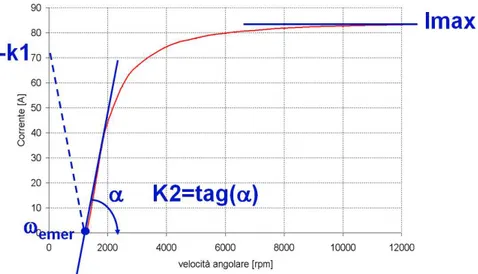
By considering the battery voltage constant and assuming N conductors, in Figure 3.3 it can be seen the plot of the current as a function of the angular velocity.
Figure 3.3. Alternator characteristic at E and N constant.
3333....2222GEGENERAL DESCRIPTION OFGEGENERAL DESCRIPTION OFNERAL DESCRIPTION OF SMART ALTERNATOR SYNERAL DESCRIPTION OF SMART ALTERNATOR SY SMART ALTERNATOR SY SMART ALTERNATOR SYSTEMSTEMSTEMSTEM The current state of the art of the alternator voltage regulation consists of the regulation of the rotational speed and current of the alternator in relation to an efficiency index related to the actual working point of the engine [1] [2]. This solution has, as a disadvantage, that the current depends on the electrical loads and on the battery voltage. The loads are not controllable while the latter is only slowly controllable. This approach may not take into account in an appropriate way the battery SOC. Therefore, the control action is not aimed at preserving the battery life time for as long as possible.
The proposed solution consists in the regulation of the alternator voltage on the basis of the engine and vehicle conditions so as to maximize its efficiency. This is done by using an “Intelligent Alternator Module (IAM)”, that communicates with the Engine Control Module (ECM) using the LIN protocol, and an “Intelligent Battery Sensor (IBS)” which provides the information about the battery SOC.
The main features of the management strategy are:
• switch off the alternator during tip-in manoeuvres in order to maximize the performance;
• switch off the alternator when the catalyst is cold, so as to reduce the emissions, and when it is in idle conditions if the battery SOC is high enough;
• increase the alternator load during tip-out manoeuvres, braking or cut-offs, and during shut-down in order to recover the kinetic energy otherwise dissipated as heat in the brakes;
• control the alternator voltage in steady-state as a function of battery SOC, loading it only when needed.
3333....3333LOGIC ARCHITECTURE LOGIC ARCHITECTURE LOGIC ARCHITECTURE LOGIC ARCHITECTURE
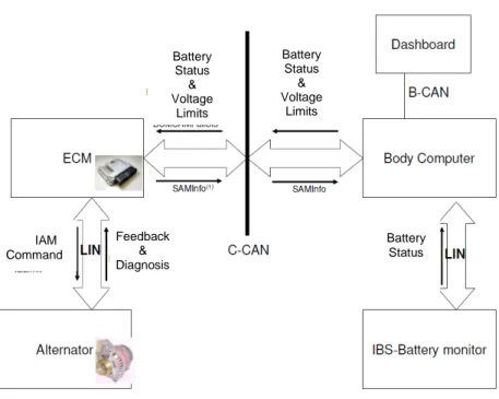
The components required to perform the above mentioned algorithm are:
• The Intelligent Alternator Module – IAM
• The Engine Control Module – ECM
• The Body Control Module – BCM
• The Intelligent Battery Sensor – IBS
Figure 3.4Logic Architecture Scheme
The ECM manages:
• The alternator, via the LIN protocol, by sending the command set-points;
• The vehicle/engine conditions to identify the driving conditions;
IAM Command Feedback & Diagnosis Battery Status Battery Status & Voltage Limits Battery Status & Voltage Limits
• The engine conditions to establish the regulation voltage boundaries versus the IAM module;
• The regulation range of voltage coming from the BCM module, comparing it to the ECM boundaries;
• The transmission of diagnostic information coming from the IAM module.
The BCM handles:
• The vehicle electrical loads (e.g. fog lights or headlights, windshield wipers, heated rear window) to establish the voltage control range and forward it to ECM module via the CAN protocol;
• The transmission to the ECM module of the information about the battery status (SOC, voltage, current, temperature) coming from IBS module;
• The alternator warning lamp for announcing fault occurrences. The IAM manages:
• The voltage regulation, starting from the set-point received via LIN from ECM;
• The delivering of the feedback messages coming from the alternator (e.g. diagnostic information, operating duty cycle).
3333....4444ALGORITALGORITHALGORITALGORITHHHMMMM DESCRIPTION DESCRIPTION DESCRIPTION DESCRIPTION
The main states of the Smart Alternator Management (SAM) strategy are:
• PB : Passive Boost, in which the alternator is switched off during
tip-in manoeuvres. When a fast increase or, alternatively, a high absolute level of torque is required, the ECM controls the alternator with the voltage level as low as possible, according to the voltage limits imposed by the BCM module.
• RB: Regenerative Braking, in which the alternator is regenerating
in braking manoeuvres. When the vehicle is decelerating (braking or cut-off manoeuvres) the ECM controls the alternator with the voltage level as high as possible, according to the voltage limits imposed by the BCM module.
• SS: Steady State, in which the Battery SOC is controlled. Outside
the above conditions, the ECM controls the voltage to maintain an optimal SOC, chosen as a trade-off value between fuel consumption and battery life.
• CE: Cold Engine Management, in which the alternator is switched
on during cold conditions in order to increase the engine load for quickening the catalyst light-off phase.
• CRK: Cranking Management, in which the IAM is managed during
engine crank or automatic re-start (for Stop & Start feature). During the cranking phase, depending on the engine speed, two starting sub-phases are defined in which the set-point voltage regulation is kept low at first, in order to facilitate the engine speed rising, and then is increased (with ramp law) to a high value, in order to reduce the engine speed overshoot in the post-cranking phase without compromising the FEAD (Front End Accessory Drive) system performance.
• SHUTOFF: Shutoff Management, in which the IAM is managed
during engine shutdown (either manually from the driver or automatically from a Stop & Start strategy). During an engine shut down the ECM module controls the alternator with the voltage level as high as possible, according to the limits imposed by BCM module, in order to increase engine load for reducing engine bouncing during shutdown and quickening the whole maneuver.
• QC: Quick Charge, when the SOC is too low, it’s required that the
alternator is set to the highest possible voltage level in order to quicken recharges the battery.
• NP: Normal Production, in which the IAM is set in the case of
recovery. In the case of fault occurrences in the system (either components or communication lines), the ECM controls the alternator with typical voltage set-points of current productions (usually with values between 13.5V and 14.5V).
Figure 3.5 State flow diagram of Smart Alternator Management In PB, RB, QC states, two controls are applied by ECM: one in open-loop, used to calculate the target voltage set-point and one in closed-loop based on a filtered battery voltage signal, where the instantaneous noise on the IBS measurement is reduced.
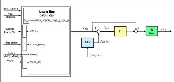
The first alternator control algorithm, used in Passive Boost state, is in charge to determine the target voltage Vobj. through the following steps:
• compute the VECMlim voltage, that is related to the vehicle electronic
equipment rotating with the internal combustion engine, e.g. the engine cooling fan assembly rotating to a preset speed;
• compute the V1(Ibat) voltage, which is related to the current
generation of the electrical battery.
VECMlim corresponds to a minimum preset alternator voltage which is enough
to supply the active electronic equipment on the vehicle; the voltage V1(Ibat)
basically corresponds to a minimum predetermined voltage necessary to prevent an excessive battery current draining during the electrical supply. This term has been studied in order to guarantee a safety monitoring of the battery.
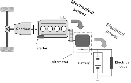
The Figure 3.7 shows the Alternator position and feature in the vehicle, and how the electrical loads are represented.
Figure 3.7Alternator feature scheme.
The first alternator control algorithm, as showed in Figure 3.9, starts to define Vobj which establishes the lower voltage limit of the SAM strategy, as
defined below:
(
)
(
MIN ECM bat meas)
obj