Alma Mater Studiorum – Università di Bologna
DOTTORATO DI RICERCA IN
MECCANICA E SCIENZE AVANZATE
DELL'INGEGNERIA
Ciclo XXX
Settore Concorsuale di afferenza: 09/A3 Settore Scientifico disciplinare: ING-IND/14
ANALYSIS OF DRILLING OF COMPOSITE LAMINATES
Presentata da:
NAVID ZARIF KARIMI
Coordinatore Dottorato
Supervisore
Prof. Marco Carricato
Prof. Giangiacomo
Minak
DECLARATION
I hereby declare that except where specific reference is made to the work of others, the contents of this dissertation are original and have not been submitted in whole or in part for consideration for any other degree or qualification in this, or any other university. This dissertation is my own work and contains nothing which is the outcome of work done in collaboration with others, except as specified in the text and acknowledgements.
Navid Zarif Karimi December 2017
To my wife who has always support me during the past three years of my doctoral journey.
ACKNOWLEDGEMENTS
I would like to extend my special thanks and appreciation to Professor Giangiacomo Minak, my academic advisor during the doctoral study period. His personal interest, patience, guidance and support helped refine the ideas presented in this thesis and provided me with rewarding academic and research experience. He has been very supportive and caring, not only in regard to my academic progress, but also about many other issues that I was involved with besides my Ph.D. study.
Many thanks to the reviewers for agreeing to serve on my committee. Their thoughtful evaluation, constructive suggestions, and criticism were helpful in keeping this work on purpose.
I wish to extend my sincere thanks to Dr. Hossein Heidary for his assistance in refining the ideas for this research and close involvement in expediting my research activities. Many of my accomplishments would not have been realized without his help.
I am most grateful to Professor Michael Wisnom, director of the advanced composite centre for innovation and science, for inviting me as a visiting researcher at University of Bristol. I also would like to extend gratitude to Dr. Mohamad Fotouhi and Dr. Meisam Jalalvand for their support during this period.
I would also like to thank Mr. Paolo Proli for his technical advice and assistance in accessing resources, material preparation and testing. Assistance of Mr. Ruggero Maria Vittori throughout the experimental work is appreciated.
My special appreciation goes to my parents; their faith in me has been and will always be my drive to excel. This doctoral degree is a manifestation of many years of ambition and sacrifice that my parents have undergone for me to achieve; without their tender loving care and support, my education in Italy would not have been possible. I owe them everything and wish I could show them just how much I love and appreciate them.
Above all, my deep appreciation and love goes to my wife, Parnian Kianfar. She has been devoted herself full time to support me during the last three years. She is the single person who has experienced the greatest hardship during this period, even so she has cheered me on when I was discouraged. I would like to thank her for being patient and firm, a pillar of strength and moral support throughout, often more determined than I.
SOMMARIO
I materiali compositi avanzati sono caratterizzati dalla combinazione di alte rigidezza e resistenza specifiche. Di conseguenza i compositi hanno attirato un’attenzione crescente per varie applicazioni industriali. L’espansione dell’utilizzo di materiali compositi richiede l’impiego di differenti tipologie di lavorazione di macchina utensile. Una delle più comuni è la foratura, usata per favorire l’assemblaggio di sotto componenti in composito. Lo scarto di parti in composito allo stadio del montaggio a causa della scarsa qualità dei fori che presentano danni indotti dalla foratura è una seria preoccupazione per le industrie manifatturiere. Non è né pratico né economico interrompere il processo di foratura per controllare eventuali danni, perciò c’è grande necessità di un controllo continuo senza interruzione del processo. Questa Tesi affronta il problema della caratterizzazione, della modellazione e del controllo continuo del processo di foratura attraverso differenti metodologie sperimentali e analitiche.
Sono stati sviluppati modelli analitici che predicono la spinta critica e l’avanzamento critico, valori oltre i quali la delaminazione inizia a propagare durante la foratura di compositi multidimensionali. L’area delaminata è stata modellata come una piastra circolare con i bordi incastrati e soggetta a differenti profili di carico in corrispondenza dei taglienti e della punta del trapano. Utilizzando la meccanica della frattura e la teoria classica dei laminati sono state ottenute delle espressioni analitiche per la spinta critica e l’avanzamento in differenti posizioni della lamina. Una strategia ad avanzamento variabile p stata suggerita al fine di ridurre la delaminazione in maniera da ottimizzare i tempi di foratura. I modelli proposti sono stati verificati sperimentalmente e paragonati con i modelli disponibili in letteratura. I valori predetti dal modello mostrano un accordo soddisfacente con quelli misurati. Si è visto che i nuovi modelli forniscono risultati più accurati dei precedenti.
La qualità dei fori ed il danno indotto dal processo di foratura di laminate composite è stato studiato sperimentalmente. L’influenza dei parametri di foratura, della geometria dell’utensile e del materiale da forare è stata studiata attraverso misurazione e esami qualitativi. Molti indici di qualità della foratura sono stati misurati, come la forza di spinta, l’area delaminata, la resistenza residua a compressione e a flessione. L’effetto dei parametri principali di foratura su questi indici è stato analizzato statisticamente e sono state identificate le condizioni ottimali di foratura per avere ottime prestazioni e fori non danneggiati. I risultati sperimentali hanno mostrato che la scelta delle condizioni di foratura è critica per le prestazioni del foro, specialmente nel caso di materiali con funzione strutturale.
Inoltre, è stato eseguito studio sperimentale basato sulle Emissioni Acustiche come strumento di controllo in linea e di valutazione non distruttiva della foratura dei compositi. Le Emissioni Acustiche sono state usate per esaminare la relazione tra segnale di risposta e danno da foratura. Diverse quantità caratteristiche delle EA sono state misurate, tra cui ampiezza, frequenza media, energia, conteggi, tempo di salita e durata del segnale. E’ stata presentata una procedura per la
differenti sistemi di acquisizione e analisi del segnale. I risultati hanno consentito di determinare lo spettro e il contenuto energetico dei meccanismi di danneggiamento più importanti durante la foratura. Infine si è concluso che le Emissioni Acustiche hanno un grande potenziale per il controllo in linea e la caratterizzazione del danno da foratura.
Parole Chiave: Foratura, Laminati Compositi, Delaminazione, Modellazione Analitica, Controllo
ABSTRACT
Advanced composite materials are characterized by having a combination of high specific strength and stiffness. As a result of these remarkable properties, composites have attracted increasing attention for use in many industries. The application expansion of composite materials calls for the use of different types of machining operations; of which drilling is one of the most commonly used processes in the assembly of composite sub-components. Rejection of composite parts at the assembly stage due to the poor-quality hole with drilling induced damages is a serious concern for manufacturing industries. It is neither practical nor economical to interrupt the drilling process and inspect these damages; therefore, there is a great need for online monitoring method without interrupting the process. This dissertation deals with the characterization, modeling, and monitoring of drilling process of composite materials through various experimental and analytical investigations.
Analytical models were developed which predicts critical thrust force and critical feed rate above which the delamination crack begins to propagate in the drilling of multi-directional laminated composites. The delamination zone was modeled as a circular plate, with clamped edge and subjected to different load profiles for cutting lips and chisel edge regions. Based on fracture mechanics, classical laminate theory and orthogonal cutting mechanics, expressions were obtained for critical thrusts and critical feed rates at different ply locations. A variable feed rate strategy was then suggested with the aim of avoiding delamination while drilling in a time-optimal fashion. The proposed models have been verified by experiments and compared with the existing models. Based on the results, the predicted values by the proposed models show satisfactory agreement with the experimentally measured values. It was found that the new developed models provide more accurate and rigorous results than the formers.
Quality of holes and drilling-induced damage when drilling fiber reinforced composite laminates were experimentally studied. The influence of drilling parameters, tool geometry, and workpiece material on the resulting quality of the produced hole and damage were studied through qualitative measurements and examinations. Several quality responses were measured as indices of drilling performance, including thrust force, delamination size, residual compression strength, and residual flexural strength. Effects of key drilling parameters on these responses were statistically analyzed, and optimal drilling conditions for high performance and free-damage drilling were identified. Experimental results revealed that the choice of drilling conditions is critical to hole performance especially when these materials are subjected to structural loads.
An experimental study of acoustic emission as a tool for in-process monitoring and nondestructive evaluation of drilling of composites was conducted. Acoustic emission was used to examine the relationship between signal response and drilling induced damages. A number of AE features were measured to characterize the process, including amplitude, average frequency, energy, counts, rise time, and duration of the signals. A procedure for discrimination and identification of different
analysis tools. Based on the results, frequency distribution and energy percentage of most important damage mechanisms occurring during drilling were determined. Finally, it was concluded that acoustic emission has a great potential for the application of online monitoring and damage characterization in the drilling of composite structures.
Keywords: Drilling, Laminated Composites, Delamination, Analytical Modeling, Acoustic
Table of Contents
ACKNOWLEDGEMENTS ... v
SOMMARIO ... vi
ABSTRACT ... viii
List of Figures ... xiii
List of Tables ... xvi
Nomenclature ... xviii
1 INTRODUCTION ... 1
1.1 Composite materials ... 1
1.2 Problem statement ... 3
1.3 Motivation and research objectives ... 4
1.4 State of the work... 5
2 ANALYSIS OF DELAMINATION ... 7
2.1 Delamination mechanism... 7
2.1.1 Delamination at the hole entry ... 8
2.1.2 Delamination on the hole exit ... 9
2.2 Supported and unsupported drilling... 9
2.3 Factors affecting delamination ... 12
2.4 Assessment of delamination ... 15
2.5 Modeling delamination propagation ... 17
2.5.1 Analytical model for push-out delamination... 19
2.5.2 Analytical model for peel-up delamination ... 21
2.5.3 Analytical model for orthotropic materials ... 21
2.6 Drilling thrust force and torque ... 22
2.6.1 Influence of drilling parameters on thrust and torque ... 23
2.7 Approaches to prevent delamination ... 27
2.7.1 Back-up plate ... 27
2.7.2 Special drill bits... 28
2.7.3 Pre-drilled pilot holes ... 29
2.7.5 Two-side drilling ... 30
2.7.6 High speed drilling ... 30
2.8 Delamination and residual mechanical properties ... 31
3 ANALYTICAL ANALYSIS ... 32
3.1 Cutting force models for drilling ... 32
3.1.1 Formulation of cutting force model ... 33
3.2 Analytical model for delamination propagation ... 37
3.2.1 Physical model ... 37
3.2.2 Loading models ... 39
3.3 Experimental validation and comparison with existing models ... 48
4 EXPERIMENTAL PROCEDURE... 51
4.1 Material preparation ... 51
4.1.1 GFRP composites ... 51
4.1.2 Nano filled GFRP composites ... 51
4.2 Experimental setup ... 52
4.2.1 Drilling tests ... 52
4.2.2 Drill tools ... 53
4.2.3 Drilling fixture ... 53
4.2.4 Drilling force measurement ... 54
4.2.5 Post-drilling mechanical test ... 55
4.2.6 Microstructure observation ... 56
4.2.7 Acoustic emission measurement ... 56
4.3 Plan of experiments ... 57
4.3.1 Full factorial design ... 57
4.3.2 Taguchi method ... 57
4.4 Statistical analysis methods ... 59
4.4.1 Analysis of variance ... 59
4.4.2 Taguchi S/N ratio analysis... 59
4.4.3 Multi-objective optimization: Grey relational analysis ... 60
5 Analysis, Results and Discussion ... 62
5.2 Delamination ... 67
5.3 Effects of drilling parameters on mechanical strength ... 72
5.3.1 Residual compression strength ... 72
5.3.2 Residual flexural strength ... 77
6 ACOUSTIC EMISSION MONITORING ... 85
6.1 Historical background ... 85
6.2 Theoretical considerations ... 86
6.3 Evaluation of acoustic emission signals ... 86
6.4 Application to monitor machining of composites ... 88
6.5 Literature review ... 88
6.6 Clustering methodology ... 90
6.6.1 Fuzzy c-means clustering... 90
6.6.2 Principal component analysis... 93
6.6.3 Wavelet Analysis... 95
6.7 Damage characterization ... 96
6.7.1 Multivariable analysis of AE data ... 96
6.7.2 Wavelet-based methodology for AE analysis ... 101
7 CONCLUSIONS AND FUTURE WORK ... 106
7.1 Conclusions ... 106
7.2 Recommendations for future works... 108
Bibliography ... 109
List of Publications ... 119
International Journals ... 119
Conferences ... 119
Appendix A: Calculating reduced bending stiffness matrix ... 121
List of Figures
Figure 1.1. Schematic representation of common drilling induced damage. ... 3
Figure 2.1. SEM images of delamination; (a) intersection image of GFRP, and (b) surface image of CFRP [5]. ... 7
Figure 2.2. Schematic of peel-up delamination at the hole entry side in drilling of laminated composites. ... 8
Figure 2.3. Schematic of push-out delamination on the hole exit in drilling of laminated composites. ... 9
Figure 2.4. Schematics of supported and unsupported drilling [7]. ... 10
Figure 2.5. Thrust force and cutting torque in supported and unsupported drilling [7]. ... 11
Figure 2.6. Graph of relative drill point-workpiece speed during unsupported drilling [7]. ... 11
Figure 2.7. Mechanism of indentation during unsupported drilling [7]. ... 11
Figure 2.8. Schematic of the measurement of the delaminated area 𝐴𝑑 and the maximum diameter 𝐷𝑚𝑎𝑥. ... 15
Figure 2.9. Critical cases when drilling FRP laminates; (a) fine cracks, and (b) uniform damage area [35]. ... 16
Figure 2.10. Circular plate model for delamination analysis [50]... 20
Figure 2.11. Schematic shape of the delamination zone in a unidirectional laminate [44]. ... 21
Figure 2.12. forces when drilling composite laminates using a back-up plate. ... 28
Figure 2.13. Different drill bits; (a) standard twist drill, (b) candle stick drill, (c) multifaceted drill, (d) straight flute drill. ... 29
Figure 2.14. Drilling hole in a pre-drilled laminate... 29
Figure 2.15. Variable feed rate strategy for delamination free drilling; staircase type and a continuous variation of feed rate along the depth of workpiece. ... 30
Figure 3.1. Cutting forces in orthogonal and oblique models. ... 34
Figure 3.2. The nomenclature of the twist drill features. ... 34
Figure 3.3. The forces exerted on main cutting lip and the drilling rake angle. ... 36
Figure 3.4. Axisymmetric circular plate subjected to rotationally axisymmetric loads. ... 39
Figure 3.5. Concentrated central load model for delamination analysis. ... 40
Figure 3.6. Correlation between critical feed rate and uncut depth under drill tool. ... 42
Figure 3.8. Uniformly distributed loads model for delamination analysis. ... 45
Figure 3.9. Equivalent loading system of Figure 3.8 ... 45
Figure 3.10. Effect of chisel edge radius on critical thrust force predicted by Eq. (3.58a). ... 48
Figure 3.11. Critical thrust force, 𝐹𝑡ℎ, varying with the ply number, 𝑛, from the bottom side. .. 50
Figure 4.1. Experimental setup of drilling. ... 53
Figure 4.2. HSS twist drill bit used in the experiments. ... 53
Figure 4.3. Fixture of experimental drilling tests. ... 54
Figure 4.4. Measurement of drilling thrust force. ... 54
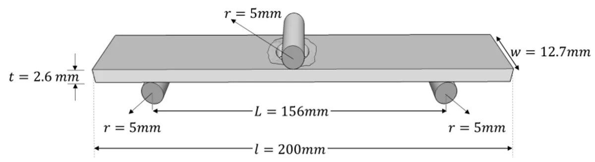
Figure 4.5. Schematic of test specimen and instrumentation for compression test... 55
Figure 4.6. Schematic of experimental setup for three-point bending test on dilled specimens... 56
Figure 4.7. Acoustic emission monitoring during the drilling process. ... 57
Figure 5.1. Load versus displacement in static test (a) flat cylindrical indenter [113] (b) conical indenter [114, 115]. ... 63
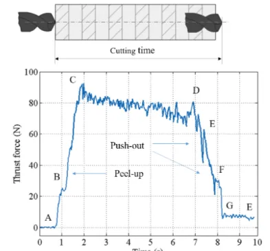
Figure 5.2. The thrust force plot during drilling at feed rate of 𝑓 = 63 mm/min and spindle speed of 𝑆 = 630 rpm. ... 64
Figure 5.3. SEM images showing (a) matrix cracking and delamination during entry stage and (b) fiber failure during cutting stage. ... 64
Figure 5.4. Contribution percent of input variables on thrust force. ... 66
Figure 5.5. Main effects plot for S/N ratios of thrust force. ... 67
Figure 5.6. Measurement of the delaminated area (Ad) of specimens at the exit side. ... 68
Figure 5.7. Pareto chart of process parameters for delamination factor. ... 69
Figure 5.8. Main effects plot for S/N ratios of delamination factor. ... 70
Figure 5.9. The interaction plots for mean values of measured delamination factors. ... 71
Figure 5.10. Positive linear relationship between thrust force and adjusted delamination factor. 71 Figure 5.11. A typical specimen during compression test. ... 72
Figure 5.12. Residual compressive strength for different drilling conditions vs. (a) displacement, (b) delamination factor... 73
Figure 5.13. Main effects plot for residual compressive strength. ... 74
Figure 5.14. Residual plots for residual compressive strength. ... 75
Figure 5.16. (a) The interaction plot and, (b) the contour plot of the residual compressive
strength... 76
Figure 5.17. The response surface of the polynomial regression model for residual compressive strength... 77
Figure 5.18. A typical drilled specimen during the bending test. ... 78
Figure 5.19. Contribution percent of input variables on residual flexural strength. ... 79
Figure 5.20. Main effects plot for S/N ratios of residual flexural strength. ... 80
Figure 5.21.Response graph for the grey relational grade. ... 83
Figure 6.1. The two typical types of acoustic emission signals; Continuous emission and Burst emission. ... 86
Figure 6.2. The definitions for a typical acoustic emission signal during drilling process. ... 87
Figure 6.3. Fuzzy c-means clustering algorithm. ... 93
Figure 6.4. Wavelet packet transform tree. ... 96
Figure 6.5. The percent of the total variability explained by each principal component. ... 97
Figure 6.6. Clustering procedure of AE signals collected during drilling process. ... 98
Figure 6.7. PCA visualization of the fuzzy c-means clustering. ... 98
Figure 6.8. Time-based features of AE signals collected during drilling process; Cumulative count, Mean power, amplitude, cumulative energy, RMS, average frequency. ... 99
Figure 6.9. Thrust force and AE amplitude variation versus time in drilling process. ... 99
Figure 6.10. Regenerated amplitude distribution after first classification. ... 100
Figure 6.11. Regenerated amplitude distribution after second classification. ... 100
Figure 6.12. Energy percentage of each component of level 3, energy (%) vs. waveform number. ... 102
Figure 6.13. FFT of the decomposed components of level 3, FFT amplitude (mV2/Hz) vs. frequency (Hz). ... 103
Figure 6.14. SEM images showing (a) matrix cracking and delamination during entry stage and (b) fiber failure during cutting stage. ... 104
List of Tables
Table 2.1. Empirical models for delamination factor in drilling fiber reinforced plastics. ... 13
Table 2.2. Analytical models for predicting critical thrust force at the onset of delamination in drilling process. ... 18
Table 2.3. Empirical models for thrust force in drilling FRPs. ... 25
Table 3.1. Material properties of 914/T300 carbon/epoxy composite laminate. ... 49
Table 3.2. Variation of critical thrust force with ply number. ... 50
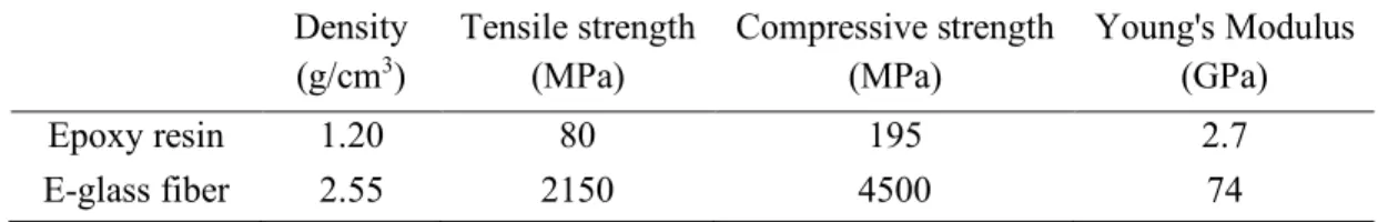
Table 4.1. Properties of matrix and fibers used for GFRP composites. ... 51
Table 4.2. Properties of functionalized multi-walled carbon nanotubes. ... 52
Table 4.3. Specification of the drill bits used in the experiments. ... 53
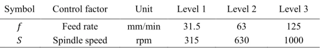
Table 4.4. Factors and levels selected for drilling of compression specimens. ... 57
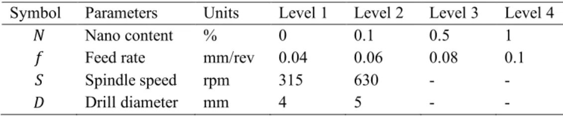
Table 4.5. Factors and levels selected for drilling of bending specimens. ... 58
Table 4.6. The L16 orthogonal array layout. ... 58
Table 5.1. Measured experimental results for thrust force ... 65
Table 5.2. Analysis of variance table for thrust force. ... 66
Table 5.3. Response table for signal to noise ratios for thrust force. ... 67
Table 5.4. Measured experimental results for delamination factor. ... 68
Table 5.5. Analysis of variance table for delamination factor. ... 69
Table 5.6. Response table for signal to noise ratios for delamination factor. ... 70
Table 5.7. The design matrix and measured experimental results. ... 73
Table 5.8. Analysis of variance for residual compressive strength. ... 74
Table 5.9. The L16 orthogonal array layout and measured experimental results. ... 78
Table 5.10. Analysis of variance table for residual flexural strength. ... 79
Table 5.11. Response table for signal to noise ratios for residual flexural strength. ... 80
Table 5.12. Data preprocessing of the experimental results, the reference sequence is 1. ... 81
Table 5.13. The calculated grey relational coefficient, grey relational grade, and the corresponding order. ... 82
Table 5.14. Response table for grey relational grade. ... 83 Table 5.15. Results of drilling performances using the initial and optimal machining parameters.
Nomenclature
𝐴1 Nominal hole area
𝐴2 Delaminated area
𝐴345 Maximum area of delamination zone
𝑎 Crack radius
𝐷 Bending rigidity
𝐷6 Effective bending rigidity
𝐷1 Nominal hole diameter
𝐷345 Maximum diameter of delamination zone
𝐸 Modulus of elasticity
𝐹8 Delamination factor
𝐹84 Adjusted delamination factor
𝐹9 Projection of force on drill axis
𝐹9: Horizontal force
𝐹;: Vertical force
𝐹<∗ Critical thrust force
𝐹>∗ Critical peeling force
𝑓 Feed rate
𝐺 Geometrical parameter
𝐺@A Critical strain energy release rate in mode I
ℎ Uncut thickness
ℎ2 Cutting depth
𝐻 Plate thickness
𝑖 Inclination angle
𝐾E Specific energy for vertical force
𝐾E,G9HIJK Specific energy at chisel edge
𝑘M Peeling factor
𝑛 Number of plies
𝑞 Uniform distributed load
𝑞P Uniform distributed load exerted on cutting lips 𝑞A Uniform distributed load exerted on chisel edge
𝑅 Nominal drill radius
𝑟 Radial coordinate
𝑟G Chisel edge radius
𝐹S9 Thrust force
𝐹S9P Thrust force exerted on cutting lips
𝐹S9A Thrust force exerted on chisel edge
𝑇JUM Experimental thrust force
𝑡 Cutting depth
𝑡G Half the thickness of the chisel edge
𝑈 Stored strain energy
𝑈2 Strain energy absorbed by crack growth
𝑉G Cutting speed
𝑊 Work done
𝑤 Deflection of plate
𝛾 Rake angle
𝛾G Chisel edge rake angle
𝛾2 Dynamic portion of rake angle
γ\ Average rake angle
𝛾I Static portion of rake angle
𝜀 Drill point angle
𝜌 Normalized radius
𝜑 Chisel edge angle
CHAPTER 1
1 INTRODUCTION
As composite materials become more and more popular, a growing emphasis is placed on manufacturing and fabricating them better, cheaper and faster. Several non-traditional machining processes such as laser cutting, water-jet cutting, ultrasonic cutting, electro-discharge machining, etc. have been developed to machine the composite materials. However, conventional machining processes such as drilling continue to be widely in use. When compared to conventional metallic materials, drilling composites pose additional difficulty due to their unique nature, microscopical inhomogeneity, anisotropy and laminate structure. Therefore, it is important to push the existing technologies to the limit so as to optimally exploit them as well as to develop more advanced drilling processes for composites. The present study embodies both of these aspects.
First part of this chapter discusses composite materials, their applications, fabrication methods, and the problems associated with machining of them. In the second part, the motivations, objectives, and organization of the dissertation are described.
1.1 Composite materials
Composite materials are multi-phase materials obtained through the artificial combination of different materials in order to attain properties that the individual components by themselves cannot attain. In contrast to metallic alloys, each material retains its separate chemical, physical, and mechanical properties. The primary reason for using composite materials is their high strength and stiffness, combined with low density, when compared with conventional engineering materials. Additionally, by deliberately designing the constituent materials, their proportions, and the orientation of each ply in the laminate, one can tailor material properties to fit specific needs. Composite materials are usually composed of a reinforcing material embedded in a base material. In most cases, the reinforcement is harder, stronger, and stiffer than the base phase, hence it provides the key structural properties of the material; high specific strength and modulus. The reinforcing phase is typically in the form of particulates or fibers. Particulate composites tend to be weaker and less stiff than fibrous composites, but they are usually cheaper [1] .
Fibers
The primary function of the fibers is to carry the loads along their longitudinal directions. Generally, fibers are classified into two division by fiber length; continuous fibers, and short fibers. Continuous fiber composites normally have a preferred orientation, while discontinuous or short fiber composites generally have a random orientation. Continuous fiber composites are used where higher strength and stiffness are required, at a higher cost, and discontinuous fiber composites are used where cost is the main driver and strength and stiffness are less important. Examples of
continuous reinforcements include unidirectional, woven, and helical winding. While examples of short reinforcements are chopped fibers and random mat.
Although a wide variety of fiber materials are available today, carbon fiber reinforced polymers (CFRPs) and glass fiber reinforced polymers (GFRPs) are by far the most common fiber reinforced composites in many industries in view of their specific mechanical properties. Glass fiber reinforced polymers have comparatively lower cost to carbon base composites results in more applications of GFRPs. Carbon fiber reinforced polymers are relatively expensive construction materials and therefore used when their properties of lightness and strength are of paramount importance, such as aerospace applications.
Matrix
The base phase is the matrix that performs three main functions; to hold the fibers in the proper orientation and spacing, to distribute the load between the fibers, and to protect the fibers from abrasion and the environment. In order to fulfill these tasks, an ideal matrix material should possess the following properties; it should initially be a low-viscosity liquid that is converted to a tough durable solid, it should wet the fibers and form a strong interface, and it should exhibit a high shear strength. The matrix can be a polymer, metal, or ceramic. Polymers have low strength and stiffness, metals have intermediate strength and stiffness while high ductility, and ceramics have high strength and stiffness but are brittle.
Polymer-matrix composites offer very high strength-to-weight and stiffness-to-weight ratios, and the aerospace industry is making a major effort to incorporate an increasing number of fiber reinforced polymer (FRP) laminates into various components and structures. Among polymers used for structural composites, epoxy is being used extensively which is also utilized in the current work. It has the advantageous of non-volatility, good thermal and dimensional stability, and high bond strength.
Applications
Most fiber reinforced polymers for structural use are laminated. FRP laminates can be tailored for various properties by appropriately choosing their components, their proportions, their distributions, their morphologies, their degrees of crystallinity, crystallographic textures, as well as the structure and composition of the interface between components. Owing to this strong tailorability, composite laminates can be designed to satisfy the needs of technologies relating to the aerospace, automobile, electronics, construction, energy, biomedical and other industries. As a result, composite materials constitute most commercial engineering materials.
Fabrication and manufacturing process
As FRPs have gained great importance in various applications, several processing techniques have been developed to fabricate them with a uniform fiber distribution and high degree of alignment. Each process has its own usefulness for combining different kinds and amounts of fibers and resins. The basic processes can be categorized into two classes: open mould and closed mould processes.
The open mould processes include hand lay-up, spray-up, vacuum pressure bag, autoclave, filament winding and continuous pultrusion. Closed mould processes include matched die moulding, injection moulding and resin transfer moulding [2].
1.2 Problem statement
Machining metals and composites
Although a near-net shape can be obtained in the production of components made of fiber-reinforced polymer laminates, machining processes are still required for dimensional accuracy, surface finishing and assembly with other parts [3]. The machining characteristics of composites are different from that of metals, which are well established and standardized on validated machining practices and quality requirements. Machining of composites is one of the most difficult and least understood areas in advanced manufacturing science. Poor machined quality will result in poor assembly tolerance, poor finish quality, and long-term performance deterioration.
Drilling process and challenges
Among the machining processes, drilling is the most frequently applied for composites due to the need for fastening in mechanical structures [4]. For bolted joints and assemblies, damage-free and precise holes must be drilled in the components to ensure high joint strength and precision. Furthermore, repairs in the filed often require the drilling of holes in composite laminates. The great difference between the drilling of conventional materials, basically metals, and the drilling of composite materials lies in the very unlike nature of material. Composite materials are anisotropic, locally inhomogeneous, and are mostly prepared in laminate form before they undergo the drilling process. Due to anisotropy and inhomogeneity, metal cutting techniques have to be modified considerably when applied to composite materials to avoid creating drilling induced damage, which is the subject of the current work. A schematic representation of common drilling induced damage during drilling of FRP composite laminates is shown in Figure 1.1.
Figure 1.1. Schematic representation of common drilling induced damage.
Delamination
The typical damage encountered during the drilling of composite laminates consists of delamination of layers due to the relatively poor strength of these materials in the thickness
direction. Such damage is generally initiated when the drilling force exceeds a threshold value at critical stages. The presence of delamination reduces the stiffness and strength of a laminate and thus degrades its load carrying capacity. Delamination can often be the limiting factor in the use of composite laminates for structural applications, particularly when subjected to compression, bending and fatigue loads and when exposed to moisture and other aggressive environments over a long period of time. As delamination is so detrimental, an attempt should be made to avoid delamination in the first place.
1.3 Motivation and research objectives
The drilling of FRP composite laminates is a relatively new practice, and unlike the well-established practices of metal drilling, it is still in the development stages. Regardless of the fact that ample research work has been published in the past years, many issues associated with drilling of composite materials still need further examination. The lack of comprehensive theoretical and empirical investigations is the primary motivation for this thesis study. Such investigations will provide a platform for high performance and productivity machining which is an interesting subject for manufacturing industries.
The objective of this dissertation is to study some of the challenges encountered in the production of good quality hole when drilling fiber reinforced composite laminates, and to develop a theoretical model with the goal of avoiding delamination. This model should provide reasonable correlation between cutting condition, material properties, and the occurrences of delamination. The interactions between cutting parameters, such as feed rate and cutting speed, and cutting force should be also illustrated. Additionally, residual properties of drilled composite laminates is desired. The evolution of delamination and its effect on the residual properties of drilled composite laminates requires extensive investigation. Several complimentary mechanical tests are conducted for this purpose. Last but not the least, online monitoring the drilling process is desired. Acoustic emissions of composite materials during drilling are collected for this purpose. In summary, the specific objectives of the thesis are:
1. Investigation on drilling performance of composite laminates
A parametric study of drilling composite laminates is the primary objective of this thesis to identify optimum tool and process parameters for high performance drilling. In this study, a large number of experiments will be conducted to explore the influence of different input parameters such as spindle speed, feed rate, drill bit geometry and materials on output parameters such as drilling thrust force, delamination, and residual strength. The relationship between drilling induced damages and drilling conditions and parameters will be investigated experimentally. Additionally, a series of damage tolerance tests will be performed to investigate the influence of drilling induced damages on residual strength of laminates.
Laminated fiber reinforced composites under cutting forces are subject to the risk of interlaminar crack propagation, or delamination, which threatens structural reliability. Such damage imposes a limiting factor to the machinability of composites and need new tools of analysis; therefore, is a major damage mechanism to be predicted. The present study will provide an analytical model using classical plate theory and linear elastic fracture mechanics to predict the critical cutting force and feed rate responsible for the onset of the delamination.
3. Online detection and monitoring of drilling process
Rejection of composites parts at the assembly stage due to poor quality hole with drilling induced damages is a serious concern for manufacturing industries. It is neither practical nor economical to interrupt the drilling process and inspect these damages; therefore, there is a great need for online monitoring method without interrupting the process. This study will address a new approach utilizing acoustic emission technique together with signal processing method to examine the relationship between signal response and drilling induced damages.
1.4 State of the work
The present study attempts to address some problems associated with the drilling of fiber-reinforced composite laminates and to solve those problems. It consists of analytical investigations as well as their experimental verifications. The following paragraphs provide an overview of the content of each chapter in the manuscript.
Chapter 1 discusses briefly what fiber-reinforced composite laminates are and how such materials are manufactured. It is then followed by a statement of the issues associated with machining and particularly drilling of composite materials, research motivations and objectives, and thesis outline.
Chapter 2 states the problem of delamination which composite materials exhibit during conventional machining processes. The mechanisms of the formation delamination cracks, factors affecting delamination, visualization and assessment techniques, and approches to prevenet delamination propagation are addressed. Additionally, primary analytical models for delamination mechanisms based on the theory of fracture mechanics are presened. It also includes a review of the state-of-the-art in the machinability of holes in composite laminates, incorporating a discussion of the drilling process and quality criteria currently applied to composites.
Chapter 3 describes the theories of orthogonal and oblique cutting and the mechanics of drilling operation. A modeling of the formation of delamination cracks using linear elastic fracture mechanics and classical laminated theory is then presented. Theoretical models for thrust force and feed rate are developed for a variety of loading conditions. These models are able to predict the critical values for thrust force and feed rate at the onset of delamination as a function of material properties, tool geometries, and specimen configuration. The validity of the model is confirmed
Chapter 4 is concerned with the experimental procedure. Workpiece material preparation, experimental setups, machine tools, test procedures, and measurement techniques are covered in this chapter. Methods employed to design the experiments, selection of input factors, corresponding levels, their ranges, and selection of the quality responses are outlined. Furthermore, statistical and analytical methods used to analyze the experimental data on the hole quality responses are described.
In Chapter 5, experimental investigations on the drilling thrust force, delamination and residual properties of the drilled specimens are carried out. The effects of cutting parameters and tool geometry as well as material properties are evaluated and discussed in details.
Chapter 6 explores the feasibility of using acoustic emission (AE) in monitoring the drilling of composite materials. It is demonstrated that AE shows a promising potential for the application of online monitoring and damage characterization. Furthermore, signal processing is expected to promote the effectiveness of the technique.
Finally, in Chapter 8, the results are summarized and specific conclusions are drawn. Recommendations for the future research in this area are also given.
CHAPTER 2
2 ANALYSIS OF DELAMINATION
The principal mode of failure of composite laminates is the separation along the interfaces of the layers, which is called delamination. In layered composites, the adjacent layers are bonded together by a thin layer of resin between them. The interface layer transfers the force from one layer to another one. If this interface weakens or damages, it causes the adjacent layers to separate. Delamination is induced by interlaminar tension and shear that develops because of various factors including free edge effects, structural discontinuities, localized disturbances during manufacturing and in working condition, such as impact of falling objects, drilling operation, moisture and temperature variations and internal failure mechanisms like matrix cracking.
Hidden from superficial visual inspection, delamination usually lies buried between the layers, and began to propagate in response to an appropriate mode of loading. Delamination drastically reduces the strength and stiffness and thus limits the life of the structure. Moreover, it causes stress concentration in load bearing plies and a local instability which leads to a further growth of interlaminar cracks, resulting in a compressive failure of the laminate. Hence, delamination is known as the most prevalent life-limiting damage growth mode.
In this chapter, the mechanisms of the formation delamination cracks, factors affecting, assessment of delamination, methods to avoid delamination propagation, and some basic theoretical models for delamination onset are described.
2.1 Delamination mechanism
Drilling induced delamination has been recognized as a major concern in machining of fiber reinforced polymer laminates because it may adversely affect the structural integrity and long-term reliability of the machined component. Figure 2.1 shows several scanning electron microscopy (SEM) images of delamination damage.
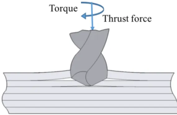
By design, each composite lamina possesses large strength and modulus along the fiber direction and low strength and stiffness in the transverse direction. As per strength requirements, several of these laminas or plies should be stacked together to possess large in-plane strength, but their out-of-plane strength is very poor. Depending on the tool geometry, material being drilled, machining parameters (such as feed rate and spindle speed), a thrust force, axial component of cutting forces, is developed during the drilling operation. This transverse thrust force is responsible for the occurrence of delamination during drilling.
El-Sonbaty et al. [6] identified two forms of delamination called “peel-up” at the drill entry point and “push-out” on the exit side of the workpiece. In practice, it has been found that the delamination associated with push-out is more severe than that associated with peel-up. The mechanisms of delamination at the entry and exit of the drilled holes periphery are discussed in the following sections.
2.1.1 Delamination at the hole entry
Delamination at the drill entry hole is called peel-up which is shown schematically in Figure 2.2. At the very beginning of drilling, the cutting edge of the drill abrades the laminate. It then, by moving forward, tends to pull the abraded material away along the flutes. The material spirals up before it is machined completely, see Figure 2.2. This spiraling action implies a peeling force upwards, which is responsible for separating the upper laminates from the uncut portion held by the compressively acting thrust force. Such peeling force results from a tensile stress filed near the cutting edge, which is produced by the cutting action. This phenomenon has been reported in the study of metal cutting, which discusses the opening of micro-cracks and separation of materials beneath the tool edge. As a result, the cutting force, which abrades the laminate, is actually what drives the structure to delaminate. The transformation from the peripheral cutting force to the axial peeling force is a complex function of drill geometry and friction between the tool and workpiece. Further work is needed to investigate this transfer function.
The first ply is most vulnerable to delamination since it has the weakest back-up support against bending. Peel-up delamination becomes progressively more difficult as drilling proceeds since the thickness resisting the lamina bending becomes greater.
2.1.2 Delamination on the hole exit
Push-out is the delamination mechanism occurring as the drill reaches the exit side of the material, where the uncut thickness is smaller and the resistance to deformation decreases. In drilling, the drill always exerts a compressive thrust force on the workpiece. In the case of composites, the laminae under the drill are subjected to bending deformation and tend to be pushed away from the interlaminar bond around the machined hole. As the drill approaches the exit, the uncut thickness becomes smaller and the resistance to deformation decreases. At a critical thickness, the interlaminar bond fails by the action of thrust force and an interlaminar crack is initiated around the hole. Further pushing down by the drill point causes the crack to propagate and the flexural rigidity of the supporting plies becomes weaker. This leads to fracturing the material below the drill point as the chisel edge proceed exiting the laminate. The fracture of the bottom surface plies occurs by both Mode I and Mode III fracture.
The last lamina is most frequently found delaminated within the laminate since it is the weakest in resisting bending deformation. Delamination often happens before the laminate is completely penetrated by the drill, as shown in Figure 2.3, leaving a damaged zone around the hole.
Figure 2.3. Schematic of push-out delamination on the hole exit in drilling of laminated composites.
2.2 Supported and unsupported drilling
The mechanism of delamination during unsupported drilling is completely different from that above is described for supported drilling. In supported drilling, a sacrificial plate or a support plate which is usually pre-drilled is placed under the workpiece. However, in unsupported drilling, there is nothing under the workpiece, hence it is free to bend due to the applied thrust force. Figure 2.4 depicts a schematic of supported and unsupported drilling.
For the better understanding of the delamination mechanism, it is helpful to analyze and compare these two drilling cases. For this purpose, the graphs of the drilling thrust force and torque as a function of the drill bit displacement are shown in Figure 2.5. The analyses of the graphs are given in the following paragraphs.
Figure 2.4. Schematics of supported and unsupported drilling [7].
During supported drilling, the thrust force increases drastically at the beginning of the process, as the chisel edge of the drill penetrates the laminate. The torque increases more slowly due to the smaller cutting forces at the chisel edge and the proximity of these forces to the center of the drill. The torque starts to increase as the cutting edges engage in cutting the laminate. The axial force increases with the entrance of the cutting lips and then oscillates around a constant mean value until delamination occurs. The thrust force and torque decrease rapidly as the drill emerges out of the laminate. The thrust force reaches zero when the drill bit fully emerges out of the laminate but the torque reaches a nonzero value as the flutes of the drill are still engaged in the workpiece. Unlink supported drilling, during unsupported drilling, the thrust force increases gradually as the workpiece begins to bend under the advancing drill bit, making the relative speed between drill and workpiece low. In fact, the actual feed rate is considerably lower than the nominal feed rate, and the overall progress of the drill tool in the laminate becomes slow. As the drill bit approaches the last uncut plies, the stress due to the thrust force exceeds its critical value and all the uncut materials are burst open. At this stage, the deflected workpiece is released and it regains its initial straight position, causing the actual feed rate increases rapidly. Figure 2.6. clearly reveals the sudden increase in the relative workpiece-drill bit speed. Moreover, the cutting torque graph shows a peak in correspondence of this phenomenon.
The thrust force has been cited as the main cause of delamination by several researchers and it is believed that higher thrust force introduces more extensive delamination to the workpiece. However, Capello [7] showed that this is not always true when drilling composite laminates. In fact, during unsupported drilling, the thrust force is smaller than in supported drilling, while the delamination is more extensive. This suggests that in unsupported drilling a different mechanism is in play and other factors should be considered.
In unsupported drilling, the actual feed rate increases from very low values at the beginning of cutting process to very high during the release movement. By increasing the feed rate, the time required for cutting operation and chip formation decreases, and instead of cutting, the drill bit penetrates the laminate by punching, which obviously cause more delamination to propagate. When the feed rate becomes high enough, the whole drill point acts as a punch on the laminate
which leads to a higher tendency for delamination. Figure 2.7 depicts how the increase in feed rate changes the cutting mechanism of the drill bit.
Figure 2.5. Thrust force and cutting torque in supported and unsupported drilling [7].
2.3 Factors affecting delamination
The onset of delamination and the extent of damage are influenced by several factors including feed rate, spindle speed, drill geometry, and material properties. In order to reduce delamination, it is necessary to develop procedures to select appropriate cutting parameters, because an unsuitable choice could lead to unacceptable material degradation.
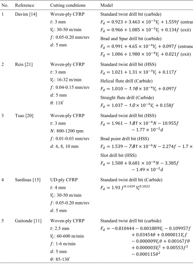
Several researchers investigated the effects of input variables, feed rate, cutting speed, point angle of twist drill bit, etc. on drilling induced delamination. Most studies show that feed rate is the most influential parameter to control delamination as it directly affects the thrust force [8-13]. Davim and Reis et al. [14, 15] conducted a series of experiments on different composite materials including GFRPs, CFRPs, and metal matrix composites to understand the effects of drilling parameters on delamination and other characteristics of these materials. Their results show that delamination increases with increasing feed rate and cutting speed. The effect of feed rate on delamination is more than that of the cutting speed. In contrast, the works conducted by Khashaba et al. [13, 16], Karnik et al. [17], and Rubio et al. [18], show that delamination decreases with increasing cutting speed during drilling of woven-ply GFRP composite laminates. Gaitonde et al. [11, 17]also reported that delamination decreases with cutting speed during high-speed drilling of thin woven-ply CFRP composite laminates. They also observed that delamination increases with increasing drill point angle. By contrast, Kilickap [19] observed that the delamination tendency decreases with increasing point angle of twist drill during conventional drilling of UD-ply GFRP composite laminates. To summarize, almost all researchers reported that drilling induced delamination increases with increasing feed rate at any different cutting speeds using various drill bits, while two different behavior for cutting speed and drill point angle effects were reported. A number of empirical models has been presented for several drill geometries to relate the delamination factor and drilling parameters. Table 2.1 gives a summary of these models. These models show the influences of feed rate, drilling speed, drill diameter, and drill type on delamination damage. Statistical analysis of the experimental results pointed out that feed rate has the greatest statistical and physical significance on delamination damage, followed by cutting speed. Additionally, the type of drill bit plays a key role in introduction of delamination. The Brad and Spur carbide drill causes the lowest delamination damage around the hole, which is followed by the helical flute carbide drill, the straight flute carbide drill, and the high-speed steel (HSS) twist drill. The reason is that delamination is closely dependent on thrust force, which in turn depends on the drill point geometry. The conventional twist drill has a large chisel edge as compared to the Brad and Spur drill, or candle stick drill, and the straight flute drill. Therefore, it produces higher thrust force and consequently higher tendency for delamination. Furthermore, HSS twist drill wears much faster than carbide twist drill, resulting in higher thrust force. Ultrasonic C-scan inspection specified that feed rate and drill diameter make the greatest contribution to drilling induced delamination. The candle stick drill and saw drill were found to cause smaller delamination factor than the twist drill [20].
Table 2.1. Empirical models for delamination factor in drilling fiber reinforced plastics.
No. Reference Cutting conditions Model
1 Davim [14] Woven-ply CFRP
𝑡: 3 mm
𝑉G: 30-50 m/min 𝑓: 0.05-0.20 mm/rev 𝑑: 5 mm
Standard twist drill bit (carbide) 𝐹2= 0.923 + 3.463 × 10kl𝑉
G+ 1.559𝑓 (entrance)
𝐹2= 0.966 + 1.085 × 10kl𝑉
G+ 0.134𝑓 (exit)
Brad and Spur drill bit (carbide) 𝐹2= 0.991 + 4.65 × 10ko𝑉 G+ 0.097𝑓 (entrance) 𝐹2= 1.006 + 1.980 × 10ko𝑉 G+ 0.021𝑓 (exit) 2 Reis [21] Woven-ply CFRP 𝑡: 3 mm 𝑉G: 16-32 m/min 𝑓: 0.04-0.15 mm/rev 𝑑: 5 mm 𝜃: 118°
Standard twist drill bit (HSS) 𝐹2= 1.021 + 1.31 × 10kl𝑉
G+ 0.117𝑓
Helical flute drill (Carbide)
𝐹2= 1.010 − 1.16 × 10ko𝑉G+ 0.097𝑓
Straight flute drill (Carbide)
𝐹2= 1.037 − 1.0 × 10kl𝑉G+ 0.158𝑓 3 Tsao [20] Woven-ply CFRP 𝑡: 3 mm 𝑁: 800-1200 rpm 𝑓: 0.01-0.03 mm/rev 𝑑: 6, 8, 10 mm
Standard twist drill bit (HSS)
𝐹2= 1.961 − 1.81 × 10ko𝑁 − 10.955𝑓
− 1.77 × 10ks𝑑
Brad point drill bit (HSS)
𝐹2= 1.539 − 7.81 × 10kt𝑁 − 2.274𝑓 − 1.7 × 10ks𝑑
Slot drill bit (HSS)
𝐹2= 1.508 + 8.681 × 10kt𝑁 − 3.385𝑓 − 1.49 × 10ks𝑑 4 Sardinas [15] UD-ply CFRP 𝑡: 4 mm 𝑉G: 30-50 m/min 𝑓: 0.05-0.20 mm/rev 𝑑: 5 mm
Standard twist drill bit (Carbide) 𝐹2= 1.93 𝑓1.vosw 𝑉 G1.v1ss 5 Gaitonde [11] Woven-ply CFRP 𝑡: 2.5 mm 𝑉G: 60-600 m/min 𝑓: 1-6 m/min 𝑑: 5 mm 𝜃: 85-130°
Standard twist drill bit (carbide)
𝐹2= −0.810444 − 0.001889𝑉G− 0.109957𝑓
+ 0.03454𝜃 + 0.000011𝑉G𝑓
− 0.000009𝑉G𝜃 + 0.00167𝑓𝜃
+ 0.000003𝑉Gs+ 0.00553𝑓s
6 Khashaba [22] Woven-ply CFRP 𝑡: 8.3 mm 𝑉G: 6.5-50.5 m/min 𝑓: 0.056-0.45 mm/rev 𝑑: 8 mm 𝑊: 0-34× 10kog
Standard twist drill bit (carbide) 𝐹2= 1.482 + 1.44 × 10kl𝑉
G+ 3.143𝑓 + 0.0193𝑊
2.4 Assessment of delamination
The visualization and assessment of delamination damage is a difficult and challenging task since damage is internal and hidden. Obtaining the size, shape, and location of delamination is essential for the assessment of machining damage. Several non-destructive inspections are frequently used to observe drilling induced delamination damage in composite laminates, including optical microscope [19, 23-25], stereomicroscope [26], ultrasonic C-scan [20, 27-30], digital photography technique [13, 16, 22], shadow moiré laser based imaging technique [31], and X-ray computerized tomography (CT) [9, 32-34].
There exist several major methods used to assess the level of delamination damage around the drilled holes. In order to quantitatively measure the amount of delamination, Chen [34] proposed a method to obtain the value of the conventional delamination factor which is defined as the ratio of the maximum diameter 𝐷\xU of the observed delamination zone to the nominal diameter 𝐷Ey\ of the drilled hole, as shown in Figure 2.8. Mathematically, this can be expressed as:
𝐹2 = 𝐷\xU
𝐷Ey\ (2.1)
Figure 2.8. Schematic of the measurement of the delaminated area 𝐴2 and the maximum diameter 𝐷\xU.
Conventional delamination factor presents satisfactory results when delamination possesses a regular pattern, as in glass fiber reinforced polymer laminates [10]. Nevertheless, when carbon fiber reinforced composite materials are drilled, delamination has an irregular form, containing breaks and cracks at the hole entry and exit. In this case, the conventional delamination factor is not an appropriate representation of the damage magnitude. Furthermore, this procedure does not take into account the damage area, as shown in Figure 2.9, where the same delamination factor is recorded for two distinct conditions. Hence, a novel approach is propose in [35], namely adjusted delamination factor, and calculated through Eq. (2.2). The first part of this equation denotes the size of the crack contribution (conventional delamination factor), and the second part denotes the damage area contribution.
Figure 2.9. Critical cases when drilling FRP laminates; (a) fine cracks, and (b) uniform damage area [35]. 𝐹2x = 𝛼𝐷\xU
𝐷Ey\+ 𝛽 𝐴\xU
𝐴Ey\ (2.2)
Where 𝐴\xU is the are related to the maximum diameter of the delamination zone (𝐷\xU), and 𝐴Ey\ is the area of the nominal hole (𝐷1). The parameters 𝛼 and 𝛽 are used as weights in the parts of Eq. (2.2). Therefore: 𝐴\xU = 𝜋 𝐷\xUs 4 (2.3) 𝐴Ey\= 𝜋 𝐷Ey\s 4 (2.4)
Substituting Eqs. (2.1), (2.3), and (2-4) into Eq. (2.2), gives:
𝐹2x = 𝛼 𝐹2+ 𝛽 𝐹2s (2.5)
In Eq. (2.5)), 𝛽 is considered as the ratio of the damage area 𝐴2 to the area corresponding to 𝐷\xU (𝐴\xU) minus the nominal hole area (𝐴Ey\). The parameter 𝛼 is the complement of 𝛽, that is, 𝛼 = 1 − 𝛽. Hence, Eq. (2.5) can be rewritten as:
𝐹2x = (1 − 𝛽) 𝐹2+ 𝛽 𝐹2s (2.6) 𝐹2x = 𝐹2+ 𝐴2 𝐴\xU− 𝐴Ey\ (𝐹2 s− 𝐹 2) (2.7) Thus, If •𝐴2 → (𝐴\xU− 𝐴Ey\) ⟹ 𝐹2x→ 𝐹2s 𝐴2 → 0 ⟹ 𝐹2x → 𝐹2x ‚
This indicates that if the trend is a delamination are equal to the crow area embody of maximum diameter (𝐷345 ) of the delamination zone, the adjusted delamination factor presents a value equal to the square of the conventional delamination factor, uniform behavior without isolated crack. Nevertheless, if the delamination area is minimal, the adjusted delamination factor presents a value tending to the convention factor, see Figure 2.9.
2.5 Modeling delamination propagation
Drilling induced delamination is directly related to the component of cutting force along the drill axis known as thrust force. Thrust force has been considered as the main cause of delamination by several researchers and it is generally believed that there is a critical thrust force below which no damage occurs [36-41]. Analytical study of this thrust force is thus interesting in order to avoid delamination.
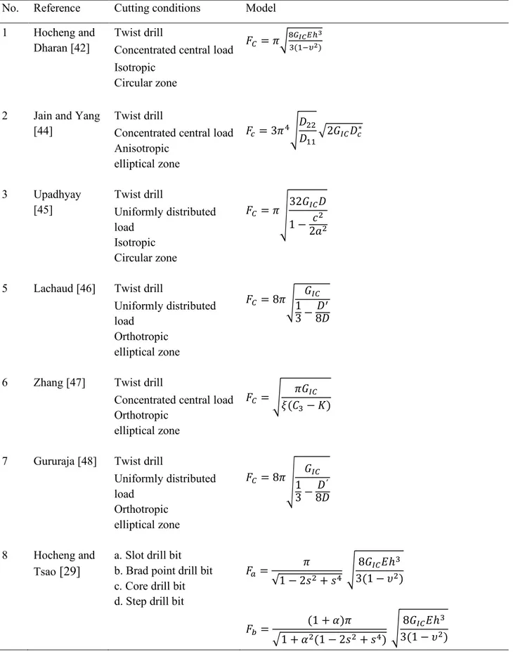
Several researchers attempted to model critical thrust force for delamination propagation. The first analytical model was proposed by Hocheng and Dharan [42]. They employed linear elastic fracture mechanics (LEFM) and classical plate theory to formulate an analytical expression to predict the critical thrust force at the onset of delamination during drilling of composite materials. The proposed model predicts the threshold load (the minimum force above which delamination is initiated) as a function of material properties and uncut-plies thickness under drill bit, as described in Section 2.5. The isotropic behavior and pure bending of laminate are assumed in their model. Jain and Yang [43, 44], developed this model, considering the anisotropy of the material and hypothesizing that the cracks are elliptical. In their model, the drilling thrust force is simplified by a representative single concentrated central load. Nevertheless, the thrust force in drilling operation does not come through the center of twist drill bit as a concentrated force, rather it is spread over the whole length of the cutting lips and the chisel edge. Upadhyay et al. [45] developed this model by assuming the thrust force as a uniformly distributed load over the drill bit diameter instead of a concentrated load.
Lachaud et al. [46] determined critical thrust force for two cases, concentrated and uniformly distributed, considering an embedded small-diameter circular plate and non-propagated cracks. Hocheng and Tsao [29] extended these models, taking into consideration a series of loading types such as circular load, concentrated centered load associated with circular load, distributed circular load, and stepwise distributed circular load for various drill types including saw drill, candle stick drill, core drill, and step drill, respectively. Table 2.2 summarized the most important analytical models proposed so far.
A positive linear correlation between delamination size and thrust force for various drill bits was observed when the applied force exceeds the critical value [13, 20, 26, 29]. This result confirms that the key for overcoming delamination when drilling FRP laminates lies in reducing the thrust force associated with drilling process through optimizing input variables.
Table 2.2. Analytical models for predicting critical thrust force at the onset of delamination in drilling process.
No. Reference Cutting conditions Model
1 Hocheng and
Dharan [42]
Twist drill
Concentrated central load Isotropic
Circular zone
𝐹A = 𝜋ƒ„…†‡ˆ9‰
l(vkŠ‹)
2 Jain and Yang
[44]
Twist drill
Concentrated central load Anisotropic elliptical zone 𝐹G= 3𝜋oŒ𝐷ss 𝐷vv•2𝐺@A𝐷G ∗ 3 Upadhyay [45] Twist drill Uniformly distributed load Isotropic Circular zone 𝐹A = 𝜋Ž 32𝐺@A𝐷 1 −2𝑎𝑐ss
5 Lachaud [46] Twist drill
Uniformly distributed load Orthotropic elliptical zone 𝐹A = 8𝜋Œ1𝐺@A 3 − 𝐷 6 8𝐷
6 Zhang [47] Twist drill
Concentrated central load Orthotropic
elliptical zone
𝐹A = Œ 𝜋𝐺@A
𝜉(𝐶l− 𝐾)
7 Gururaja [48] Twist drill
Uniformly distributed load Orthotropic elliptical zone 𝐹A = 8𝜋Ž 𝐺@A 1 3 − 𝐷 ʹ 8𝐷 8 Hocheng and Tsao [29]
a. Slot drill bit b. Brad point drill bit c. Core drill bit d. Step drill bit
𝐹x = 𝜋 √1 − 2𝑠s+ 𝑠o Œ 8𝐺@A𝐸ℎl 3(1 − 𝜐s) 𝐹• = (1 + 𝛼)𝜋 •1 + 𝛼s(1 − 2𝑠s+ 𝑠o) Œ 8𝐺@A𝐸ℎl 3(1 − 𝜐s)
𝐹G = 𝛽(2 − 𝛽)𝜋 ƒ[1 − (1 − 𝛽)o] −𝑠s[1 − (1 − 𝛽)t] 2 Œ8𝐺@A𝐸ℎl 3(1 − 𝜐s) 𝐹2= √2𝜋 𝑘 1 − 𝜐s Œ 8𝐺@A𝐸ℎl 3(1 − 𝜐s) 𝑘 = (1 − 𝜐) + 2(1 + 𝜐)𝜉 s [2(1 − 𝜐)(1 + 2𝜐s) − 12(12 − 4𝜐 + 3𝜐s+ 3𝜐l)𝜉s− 8(1 + 3𝜐)𝜉sln 𝜉] 2.5.1 Analytical model for push-out delamination
A linear elastic fracture mechanics model for predicting the onset of delamination due to the applied thrust force was developed by Hocheng and Dharan [42]. Hocheng stated that the following assumptions have to be made for the applicability of LEFM to composite materials: 1. Crack propagation must be coplanar,
2. The crack must lie in a plane of material symmetry, 3. The plastic zone at the crack tip must be very small.
Figure 2.10 depicts a twist drill and the induced delamination. In this figure, the center of the circular plate is loaded by a twist drill of diameter 𝐷, 𝐹< is the applied thrust force, 𝑥 is the tool displacement, 𝐻 is the thickness of the laminate, ℎ is the uncut depth under the tool, and 𝑎 is the assumed size of an existing crack. As the drill proceeds, the uncut laminates under the tool are pushed and deformed elastically by the thrust force. If the resulting strain at the top of the existing crack goes beyond the critical value, crack propagation occurs. The equation of energy balance can be expresses as follows using linear elastic fracture mechanics:
𝐺𝜋(𝑑 + 2𝑎)𝑑𝑎 = 𝐹<𝑑𝑥 − 𝑑𝑈 (2.8)
Where 𝐺 is the energy release rate per unit area. In Eq. (2.8), the term on the left side represents the energy required to extend the crack by a distance 𝑑𝑎. The term on the right side is the work done by the thrust force as it moves a distance 𝑑𝑥 and the second term is the stored strain energy. To find the relation between 𝐹<, 𝑥, and 𝑈, classical plate theory for a clamped circular plate
subjected to a concentrated load in the center is used in this model. This gives [49]: 𝑈 = 8𝜋𝑀𝑥s
›𝑎 + 𝑑2œs (2.9)
𝑀 = 𝐸ℎl
12(1 − 𝜐s) (2.10)
Where 𝐸 is the modulus of elasticity and 𝜐 is Poisson’s ratio. The displacement 𝑥 is: 𝑥 =𝐹<›𝑎 + 𝑑2œ
s
16𝜋𝑀
(2.11) Eq. (2.8) can, therefore, be rewritten as:
2𝐺𝜋 •𝑎 +𝑑2ž = 𝐹< 𝑑𝑥 𝑑𝑎− 𝑑𝑈 𝑑𝑎 = 𝐹< 𝑑 𝑑𝑎 𝐹<›𝑎 + 𝑑2œs 16𝜋𝑀 − 𝑑 𝑑𝑎 𝐹<s 32𝜋𝑀 = 𝐹< s ›𝑎 + 𝑑2œ 16𝜋𝑀 (2.12) Substituting Eq. (2.10) into Eq. (2.12) and solving for 𝐹<, the critical load at the onset of crack propagation can be obtained as:
𝐹<∗ = 𝜋 Ÿ8𝐺@A𝐸ℎl
3(1 − 𝜐s) v/s
(2.13) It should be noted that, in this model, critical strain energy release rate in Mode I fracture, 𝐺@A, is
used for 𝐺 since it can be easily measured, although plane strain conditions may not always be fulfilled. Nevertheless, this value, which is lower than that for the plane strain case, gives conservative predictions for the critical load. Moreover, the highest 𝐸, in the 1-direction or principal direction, is used overall for the adopted isotropic calculation instead of using a complicated derivation for the anisotropic case. This also provides a conservative prediction for the critical load.
2.5.2 Analytical model for peel-up delamination
In the case of peel-up delamination, it is assumed that the critical peeling force 𝐹>, is related to the critical thrust force by a peeling factor expressed as:
𝑘M = 𝐹<∗
𝐹>∗ (2.14)
Where 𝑘M, the peeling factor, is a function of tool geometry and friction between the tool and
workpiece.
Using the same analysis of push-out model and replacing the uncut depth ℎ by the cut thickness ℎ2 = 𝐻 − ℎ, the critical peeling force is obtained as:
𝐹>∗ = 𝜋 Ÿ8𝐺@A𝐸ℎ2l
3(1 − 𝜐s) v/s
(2.15)
2.5.3 Analytical model for orthotropic materials
In spite of the fact that the analytical model developed by Hocheng and Dharan was a good start, it has some limitations. Several assumptions are not always correct in drilling of composite laminates. For instance, the layers are assumed to be isotropic. However, each layer is highly anisotropic and a realistic shape of delamination should be taken into account. Accordingly, Jain and Yang developed a realistic model for correlating thrust force with the onset of delamination [44]. As illustrated in Figure 2.11, the delamination zone for unidirectional composites is modeled as an elliptical plate, with clamped edges and subjected to a central load. In this figure, 𝑎 and 𝑏 are respectively half the delamination sizes along the fiber and transverse directions. Based on fracture mechanics and laminated plate theory, expressions are developed for critical thrust force at which delamination is initiated at different ply location.
Figure 2.11. Schematic shape of the delamination zone in a unidirectional laminate [44]. From LEFM, the energy balance gives:
𝐹S9𝑑𝑤 = 𝐺𝑑𝐴 + 𝑑𝑈 (2.16)
Where 𝐺 is the energy release rate per unit area, 𝑈 is the stored strain energy, 𝐹S9 is the force applied, and 𝑤 is the distance moved by the drill. Using laminated plate theory, the deflection for
![Figure 2.5. Thrust force and cutting torque in supported and unsupported drilling [7]](https://thumb-eu.123doks.com/thumbv2/123dokorg/8115580.125299/29.918.270.654.173.473/figure-thrust-force-cutting-torque-supported-unsupported-drilling.webp)