A
LMA
M
ATER
S
TUDIORUM
–
U
NIVERSITÀ DI
B
OLOGNA
S
CUOLA DII
NGEGNERIA EA
RCHITETTURAD
IPARTIMENTO DII
NGEGNERIAI
NDUSTRIALEC
ORSO DIL
AUREAM
AGISTRALE INI
NGEGNERIAE
NERGETICAT
ESI DIL
AUREAin
F
ISICAT
ECNICAI
NDUSTRIALEM
ICROCHANNEL
H
EAT
E
XCHANGERS
:
AN
A
TTRACTIVE
O
PTION FOR THE
R
EGENERATOR
OF A
M
OBILE
ORC
W
ASTE
H
EAT
R
ECOVERY
S
YSTEM
C
ANDIDATOR
ELATOREAlessandro Mantovanelli Chiar.mo Prof. Gian Luca Morini
C
ORRELATORE Chiar.mo Prof. Piero ColonnaAnno Accademico 2013/14 Sessione III
Contents
Acknowledgments
III
Abstract
V
Nomenclature
VII
1
Introduction
1
1.1 Organic Rankine Cycle 5
1.1.1 Field of Application 5
1.1.2 Features of the Candidate Working Fluid 6
1.1.3 Components and Thermodynamic Aspects 8
1.2 Microchannel Heat Exchangers 10
1.2.1 Thermohydraulic Performance 10
1.2.2 Scaling Effects 15
1.2.3 Fabrication Techniques 23
1.3 Motivation and Scope 24
2
Method
27
2.1 Input Data 29
2.1.1 Benchmark Plate Heat Exchanger 29
2.1.2 Materials and Physical Properties 32
2.2 Core Geometry 33
2.2.1 Parameterization of the Geometry 35
2.3 Additional Elements 44 2.3.1 Frame 45 2.3.2 Piping 46 2.3.3 Headers 48 2.4 Mathematical Model 56 2.4.1 Thermal Design 56 2.4.2 Hydraulic Design 59
2.4.3 First Attempt Solutions 63
2.4.4 Final Design 66
2.5 Optimization Process 72
2.6 Counterflow Configuration 76
3
Results
85
3.1 Outlet Temperatures and Effectiveness 87
3.2 Magnitude of the Scaling Effects 91
3.3 Total Pressure Drop 96
3.4 Numerical Validation 97
3.5 Discussion 106
3.6 Conclusions and Recommendations 111
References
113
Acknowledgments
My gratitude goes to Prof. Gian Luca Morini and Prof. Piero Colonna for making this project possible: working under their guidance and expertise was an extraordinary learning opportunity.
Special thanks to all the guys of the Power & Propulsion Department of the TU Delft, for their help and for the time spent together. I’m grateful to Sebastian in particular, for his supervision and for the time he spent on my work.
My parents deserve tanks of thanks, for their patience and support in every imaginable way.
Finally, thanks to all the wonderful people I met during this beautiful era that is about to end, and to those who have always been there.
Abstract
The technical advancements of the last decades have made organic Rankine cycles (ORC) an attractive option for automotive applications: several examples of waste heat recovery systems suitable for internal combustion engines of heavy duty vehicles are available in literature.
Mobile power systems must be compact and light: generally heat exchangers constitute the largest part of the whole installation, hence the priority in reducing their dimensions and weight. Microchannels heat exchangers (MCHE) are distinguished by a very high ratio of surface area to volume, low thermal resistances, small volumes, low total mass and low inventory of working fluids, and are therefore the ideal candidate.
Typically, applications such as waste heat recovery usually involve heat loads and mass flow rates significantly higher than any device found in the open literature: automotive MCHE exist as proprietary or in-house packages only and have not penetrated the market yet. Further research is therefore needed to assess performance and limits of microchannel technology coupled with mobile ORC systems. The task is complicated by the sensibility of microflows to phenomena usually negligible in channels of conventional size.
The present work, carried out at the Propulsion&Power Department of Delft University of Technology, aims to design a microchannel regenerator optimized for a specific ORC waste heat recovery system, which is the target of a recent feasibility study funded by TU Delft in cooperation with two European automotive manufacturers. The system requires the regenerator to transfer around 35 kWth from the gas-side to the-liquid-side.
In the open literature, no microchannel devices are proposed above 5 kWth nor is a
suitable optimization procedure available, making the project original and innovative. The optimization process developed in this document is implemented in the MATLAB environment. Appropriate values for each design parameter describing the geometry of the MCHE core are selected in order to obtain a light and compact device. Each
parameter is allowed to vary between a maximum and a minimum value, determined from information on the manufacturing method, on the distribution elements and on the other components of the ORC system in which the MCHE is to be integrated. Some of the considerations made to establish the constraints have general validity and may come handy for diverse microchannel applications.
An important feature of the procedure is the accurate estimation of conjugate heat transfer, which is shown to have strong impact on the thermal behavior of the microchannel device. Two different alloys with substantially different thermal conductivity are considered for the solid walls, leading to remarkably different optimal design parameters.
For each material, specifically a copper-based and an aluminium based alloy suitable for the required manufacturing method, the optimization process calculates the best counterflow and crossflow configuration which satisfy the thermohydraulic requirements fed to the MATLAB script. Four optimized heat exchangers, from the lightness and compactness point of view, are provided in only a few minutes of computational time.
In order to validate the simplification introduced in the selection process, the optimal designs are rated in detail and the magnitude of the scaling effects is estimated following the guidelines available in literature. Computational fluid-dynamics (CFD) analysis of the crossflow arrangement are impracticable, but the symmetry planes of the crossflow MCHE may be exploited to single out a sufficiently contained computational domain. CFD simulations in ANSYS Fluent are in good agreement with the implemented model, with relative errors of in the order of only 0.5 % for what concern both the heat exchanger effectiveness and the total pressure drop in the core.
The optimized microchannel devices offer striking improvement in compactness and lightness compared to the exchanger originally meant for the specified ORC system. The distribution elements are found to have major impact on dimension and weight. A preliminary design is given however improvement might be needed. Experimental information on the manufacturing process and the materials are also required.
Nomenclature
Appropriate SI base and derived units eventually with metric prefixes are used throughout the present document; IEEE Standards Style is adopted for numbering and citing references, equations, figures and tables.
Acronyms
ASME American Society of Mechanical Engineers CFD computational fluid-dynamics
DN Nominal Diameter, designator used in the SI system to describe pipe size EU European Union
EU-28 the 28 member states comprised by EU since July 2013 GHG greenhouse gas: CO2 ; CH4 ; N2O ; HFCs ; PFCs ; SF6
HDV heavy-duty vehicle: motor vehicle with gross weight greater than 7500 kg IEEE Institute of Electrical and Electronics Engineers
LIGA Lithographie, Galvanoformung und Abformung MCHE microchannel heat exchanger
NADCA North American Die Casting Association NIST National Institute of Standards and Technology ORC organic Rankine cycle
PFHE plate-fin heat exchanger PHE plate heat exchanger
Roman Symbols
A heat transfer surface area, better specified by the subscript [m2] a aspect ratio of the channels on the hot-side [#]
b aspect ratio of the channels on the cold-side [#]
Br Brinkmann number [#]
C heat capacity rate [W/K]
c long dimension of the cold-side channels [m]
cP specific heat of fluid at constant pressure [ J/(kg K)]
d short dimension of the cold-side channels [m]
D diameter of the supply or return pipe, better specified by the subscript [m]
DC smallest characteristic length for heat exchanger passages [m]
DH hydraulic diameter of flow passages [m]
f Fanning friction factor [#]
G fluid mass flux, mass flow rate per unit surface area [kg/(m2 s)] h heat transfer coefficient [W/(m2 K)]
H header parameter [#]
k thermal conductivity [W/(m K)] 𝐾𝐾∞ Hagenbach’s factor [#]
Kn Knudsen number [#]
L fluid flow length on one side of the heat exchanger [m]
l long dimension of the hot-side channels [m]
LHD hydrodynamic entrance length [m]
LTH thermal entrance length [m]
Lw width of the counterflow modules [m]
m fin parameter [#]
𝑚𝑚̇ fluid mass flow rate [kg/s]
M molar mass of a gas [kg/mol]
Nc number of channels on the cold-side [#]
Nh number of channels on the hot-side [#]
Np number of plates [#]
NTU number of transfer units [#]
Nu Nusselt number [#]
p fluid static pressure [Pa]
P perimeter [m]
Pe Peclét number [m]
Po Poiseuille number [#]
Pr Prandtl number [#]
q heat flux, heat transfer rate per unit surface area [W/m2]
𝑄𝑄̇ heat transfer rate: thermal power exchanged or heat duty [W]
R universal gas constant [J/(mol K)]
r heat capacity rate ratio [#]
R thermal resistance [K/W]
Re Reynolds number [#]
S free flow area, better specified by the subscript [m2] s short dimension of the hot-side channels [m]
Sw area of the dividing wall [m2]
T fluid temperature, better specified by the subscript: static [°C] or absolute [K]
tw wall shear stress [Pa]
u fluid mean axial velocity inside the microchannel [m/s]
UA overall thermal conductance [W/K]
V volume, better specified by the subscript [m3] v fluid mean axial velocity inside the headers [m/s]
x coordinate along the flow direction of the hot fluid [m]
X non-dimensional coordinate along the flow direction of the hot fluid [m]
xh coordinate in the flow direction of the header [m]
y coordinate along the flow direction of the cold fluid [m]
Y non-dimensional coordinate along the flow direction of the cold fluid [m]
yc coordinate perpendicular to the core for the cold-side outlet header [m]
yh coordinate perpendicular to the core for the cold-side outlet header [m]
z coordinate along the no-flow or stack height direction [m]
zc coordinate perpendicular to the core for the cold-side inlet header [m]
Greek Symbols
α ratio of the total transfer area to the total exchanger mass [m2/kg] β heat transfer surface area density [m2/m3]
δ thickness of the dividing wall [m]
ϵ average surface roughness height [m]
ε heat exchanger effectiveness [#]
ηf fin efficiency [#]
ηo extended surface efficiency [#]
θ non-dimensional hot-side temperature [#]
Θ non-dimensional wall temperature [#]
ϑ non-dimensional cold-side temperature [#]
κHD dimensionless hydrodynamic entrance length [#]
κTH dimensionless thermal entrance length [#]
λ mean free path [m]
Λ longitudinal heat conduction parameter [#]
μ fluid dynamic viscosity [Pa s]
ρ mass density [kg/m3]
ϱ ratio of the cold fluid heat capacity rate to the hot fluid heat capacity rate [#]
σ ratio of the free flow area to the frontal area [#]
τ frame thickness [m]
φ fin thickness [m]
ψ generic physical property in the appropriate units of measurement
Subscripts
abrupt abrupt entrance and exit in the headers
acc acceleration
app apparent
av average
b bulk
c cold-fluid side (liquid)
f fin
fr friction
h hot-fluid side (gas)
head header in inlet max maximum min minimum out outlet p primary
pipe supply and return piping
r reference
1
Introduction
The European Union (EU) climate and energy policy targets towards 2020 include international commitments pursuant to the Kyoto Protocol and a more ambitious EU unilateral commitment, the so-called 20/20/20 triple objective [1]. Endorsed by the European Council in 2007 and implemented through the 2009 Climate and Energy Package and the 2012 Energy Efficiency Directive, this program aims to achieve the following improvements with respect to the base year 1990:
• 20 % reduction of greenhouse gas emissions
• 20 % share of renewable energy in energy consumption • 20 % increase in energy efficiency
The EU-28 Countries are essentially on track towards their respective targets: for what concerns greenhouse gas (GHG) emissions, in 2012 approximately 4544 Tg CO2
equivalents of GHE were released to the atmosphere, corresponding to 19.2 % less than base year levels. An estimated decrease of 1.3 % occurred between 2011 and 2012[2]. In the same year, the share of GHG emissions ascribable to road transport was 19.7 %, of which 98.8 % were CO2[2]. If no additional measures are adopted, the future scenarios
outlined in Figure 1 forecast a rise in emissions from this sector, in contrast to a generally decreasing trend. It is therefore evident that more efforts should be made to
limit GHG emissions especially from vehicles. The most significant existing measures include the implementation of the 2009/443/EC and 2011/510/EU Regulations and following Amendments, which set limits for CO2 emissions from new cars and light
commercial vehicles. On the other hand, heavier vehicles such as trucks and buses are currently unrestricted.
Figure 1: sectoral trends and projections of EU GHG emissions in EU-28 [1]
In 2011, heavy-duty vehicles (HDV) accounted for approximately 26 % of EU-28 road transport related CO2 [3]. Despite a CO2 emission normative specific to HDV has not
entered yet into legal force, a strategy for reducing CO2 from HDV was defined with the
2014/285/COM Communication. Climate Action Commissioner Connie Hedegaard stated short after the approval:
« Today we are taking the next steps to curb emissions from road transport. We first regulated cars and vans, and we can now see the results: emissions have been reduced,
Energy supply industries (public electricity and heat production)
Energy use (direct use of fuel in all sectors, energy supply industries and road transport excluded)
Road transport Industrial processes Waste Agriculture Solvents 0 200 400 600 800 1 000 1 200 1 400 1 600 1 800 Tg CO2 equivalents 2 000 1990 1995 2000 2005 2010 2015 2020 2025 2030
Note: Solid lines represent historic GHG emissions up to 2012 and with existing measures projections from 2010 onwards. Dashed lines represent with additional measures projections.
The projected trends were calibrated to the 2010 year of the latest inventory data, which is the base year for the projections for most Member States.
air pollution in cities is in decline, and more innovative, fuel-efficient vehicles are now available to consumers. That is why we turn now to trucks and buses. This strategy outlines new measures which over time will cut CO2 emissions of these vehicles, save
operators money and make the EU less dependent on imported oil. » *
This policy was also welcomed by the European commercial vehicle industry. Erik Jonnaert, Secretary General of the European Automobile Manufacturers’ Association, commented on the certification system introduced in the approved Communication: « Fuel efficiency is a top priority for the transport companies who buy and use trucks and buses, because fuel accounts for over one-third of their total operating costs. Fuel efficiency is therefore the number one competitive factor in developing and selling heavy-duty vehicles. This system will empower customers to compare and choose the most fuel-efficient vehicle combination adapted to their needs. » **
In order to reduce fuel consumption and therefore emissions, the documentation [3] attached to 2014/285/COM recommends several waste heat recovery technologies suitable for HDV engines, among which bottoming systems based on organic Rankine cycle (ORC) are possibly the most promising choice [4]. The literature reviewed in [5] clearly reports that fuel economy improvements around 10 % are a practicable outcome, granting a payback period of only 2-5 years.
In HDV reciprocating engines, exhaust gas energy has the highest and most technically feasible recovery potential [6] and represents a significant amount of the fuel energy, as shown in Figure 2. The exhaust gas is available at temperatures ranging from 200 to 400°C, and in the exhaust gas recirculation (EGR) system at even higher temperatures, from 280 to 580°C. [6].
ORC systems have already been widely exploited for heat recovery from stationary
* “Climate action: Commission sets out strategy to curb CO
2 emissions from trucks, buses and coaches”,
European Commission press release, Brussels, 21/5/2014
** “European auto industry welcomes transparency for customers on CO
2 from heavy-duty vehicles”,
energy sources at comparable temperature [7]. However, the implementation on board of vehicles is challenging, and it is still in research phase. Although the first ORC studies date from the oil crisis of the 1970s, no commercial application exists [6]. Recent published papers sponsored by Honda, Toyota, BMW, Wartsila and Volvo show a renewed interest in this technology, impelled by the surge in fuel prices and upcoming regulations [5]. Naturally, the ideal condition for such systems is stable engine load and speed over a large portion of operation hours [8]. This is why research concentrates on HDV designed for freight transport on long hauling routes. However, in principle this concept may be applied also to passengers car [9], which would require even more compact equipment due to reduced size.
Figure 2: typical fuel energy dissipation in a HDV [10]
Compactness and lightweight are of course crucial for mobile applications [6]. The technical advancements of the last decades in the critical components (evaporator, condenser, regenerator, expander, etc.) of ORC systems are now making them a concrete option to increase the thermal efficiency of automotive internal combustion engines [9]. However, the heat exchangers (PHE) usually employed in such systems are still considered more voluminous than desirable [6]. Generally, heat exchangers constitute the largest part of the space occupied by the whole bottoming installation, hence the priority in reducing their dimensions and weight [8]. Microchannels heat exchangers (MCHE) are ideal candidates due to several features: high ratio of surface area to
38 % 4 %3 % 3 % 8 % 29 % 15 % 52 % Useful Energy Engine Friction Driveline Friction Accessories
Waste heat available for recovery Charge Air Cooling
Exhaust Gas and EGR Heat to Engine Coolant
volume, low thermal resistances, small volumes, low total mass and low inventory of working fluids [11]. While a comprehensive literature on MCHE for electronic cooling is available, there is limited research that focuses on larger applications such as waste heat recovery. Automotive MCHE exist as proprietary or in-house packages only and have not penetrated the market yet [12]. In order to provide a better alternative to the state-of-the-art technology, it is therefore important to assess the performance of such heat exchangers in mobile ORC systems.
1.1 Organic Rankine Cycle
The organic Rankine cycle (ORC) is a Rankine cycle that does not use steam as its working fluid, but an organic fluid, i.e. a compost, not necessarily present in living organisms, containing a significant quantity of carbon [13].
1.1.1 Field of Application
Figure 3 approximately represents the field of employment, in terms of temperature and power, for heat engines using steam or organic fluids. Steam has practically no rivals in applications requiring largepower levels (higher than 500-1000 kWe) and at
medium-high temperatures (above 200-250 °C). For lower power levels, the steam turbine is usually too expensive due to several factors that increase the cost: high maximum pressure (150-300 bar) and temperature (500-700 °C) of the cycle, complexity of the plant layout (numerous regenerators) and of the turbine expander (several stages) [13]. Only few organic fluids can be operated at temperatures above 300°C, due to thermal stability issues. Temperatures below 70-100 °C make the costs of the ORC engine prohibitive, so that it is often recommended not to use them unless the power levels are particularly high, as in the case of ocean thermal energy conversion (OTEC) systems. Very low power levels (below a few tens of kWe, typical in micro-cogeneration
systems) mean high costs for the organic fluid engine and, consequently, it becomes at present often uneconomic [13].
Nevertheless, interest in the ORC technology is growing rapidly and the range of potential applications, at low and medium-high temperatures, is vast. Development potential is high in the sectors of primary generation and cogeneration (including the domestic field, within the range of a few kWe); in biomass fired systems; when there are
difficult fuels involved (syngas, flare gas, etc.); in the concentrated solar power sector; in the various forms of heat recovery (from industrial processes, from gas turbines, from reciprocating internal combustion engines, in plants for re-gasification of natural gas, etc.); in the exploitation of geothermal sources and in OTEC systems [13].
Figure 3: fields of employment for the Rankine cycle [14]
1.1.2 Features of the Candidate Working Fluid
The versatility of ORC is principally owed to the working fluid, which may also be a mixture of two or more components [15]. The fluid constituents and concentrations can be tailored to maximize the efficiency of power plants with different applications and configurations.
The selection of organic fluids, instead of steam, leads to desirable thermodynamic and
0 100 200 300 400 10 100 1000 10000 Microcogeneration
Power too low Temperature too low OTEC
Too many stages High cost Steam
Fluid stability limit
Small ORC
High temperature
Mainstream ORC
Large ORC Low Temperature
Average temperature of the source
°[C ]
turbine design features [13]:
• fluids with different critical parameters allows for thermodynamic cycle configurations otherwise inaccessible in the state diagram of water, e.g. supercritical cycles at low maximum temperatures and pressures
• even in the presence of significant differences between the temperatures of the heat source and the cold well, efficient thermodynamic cycles can be achieved through a relatively simple plant set-up, without vapor extraction and perhaps with one expansion stage, thanks to the regeneration that occurs with a de-superheating of the vapor at the turbine outlet
• the turbine generally requires modest peripheral speed and condensation is avoided during the expansion without superheating. The turbine, though, often has supersonic flows with high expansion ratios
• the choice of the fluid influences the volumetric flows, consenting turbine optimization for any power level
• pressure levels and expansion ratios may be chosen with a certain freedom, independently of the temperature levels of the heat source and the cold well, e.g. low temperatures may be associated with high pressures and high temperatures with low pressures
Inevitably, the selection of working fluids brings performance trade-offs, due to the influence of the fluid properties in most components (e.g. different condensation pressures for given saturation temperature cause wide variations in volume flows at the condenser inlet, which directly affect design and dimensions of the expander and the regenerator). Therefore, the assessment of the benefits of a particular solution must be based on the system as a whole [7]. Moreover, the choice of the working fluid is unavoidably influenced by safety and financial concerns. Consequently, it is generally the result of a compromise between the required and the desirable features of the working fluid in Rankine power systems: above all, adequate thermo-physical and thermodynamic properties, compatibility with the materials used in building the plant and the limits of thermal stability of the fluid, the health and safety issues, the fluid’s
availability and its cost [16].
1.1.3 Components and Thermodynamic Aspects
The classic configuration of the critical components of an ORC engine and the thermodynamic representation of the cycle in a T-s diagram are shown in Figure 4. The working fluid, which may be saturated as in the picture, superheated or even in supercritical conditions [17], is expanded (A → B) generally in a turbine, which in small power units may be substituted with a less expensive scroll expander [18]. In B, the temperature of the fluid might be high enough to include a recuperative heat exchanger, frequently called regenerator, in order to cool the vapor (B → C) and preheat the liquid (C → D). In the regenerator, the heat recovered is exploited to preheat (E → F) the liquid originating from the pump (D → E) and heading to the evaporator (F → A), which feeds the working fluid again to the expander.
Figure 4: T-s diagram and component layout for a hexamethyldisiloxane ORC cycle [19]
The molecular structure of the working fluid is strongly related to the shape of the saturation curve in the T-s diagram: the slope of the saturated vapor line tend to be negative for fluids with low molecular complexity like water, characterized by the
well-0 50 100 150 200 250 0 0.25 0.5 0.75 1 1.25 1.5 1.75 Temperature [°C] Specific entropy [kJ/(kg K)] A B C D, E F Turbine Evaporator Regenerator Condenser A B C D E F Pump
known bell-shaped curve, while is positive for fluids with high molecular complexity [20], as for the siloxane of Figure 4. Often organic fluids have a complex molecular structure, which usually makes the employment of a regenerator necessary to achieve an acceptable thermal efficiency. In fact, the working fluid expands from A to B in the superheated vapor region, moving away from the saturation line. Therefore, a large amount of thermal energy can be recovered from the vapor flow before it enters the condenser, raising cycle performance. This operation improves the cycle efficiency, depending on the performance of the regenerator itself [13]. It should be also noted that a positive slopes makes it possible to avoid superheating the working fluid after the evaporation without concerns of condensation inside the expander.
Phase change in ORC systems cannot always be considered isothermal. Zeotropic mixtures, i.e. multicomponent fluids whose composition can be altered through simple distillation, are characterized by a temperature difference between the dew and the bubble temperatures. This temperature glide depends on the fluids and their mass fraction in the mixture. In practice, a better thermal match between the heat source and the working fluid results in less irreversibility within the evaporator, limiting the available work lost by the system as a whole [21]. Therefore, the presence of a temperature glide could be useful from the thermodynamic point of view in those cases where the heat source is not intrinsically isothermal, as in the heat recovery of exhausts [13]. Moreover, if a refrigerant with a modest heat capacity is used for condensation, the non-isothermal phase change may still be useful in reducing the mass flow rate necessary [15]. The differences between zeotropic and azeotropic mixtures are qualitatively shown in Figure 5, where diagrams for two ORC optimized for the same heat source are reported.
An improved thermal match with heat source at variable temperature may also be obtained with supercritical heating processes, which are strongly non-isothermal. By changing the composition of the mixture, the critical point varies continually, even in a non-linear fashion [13]. Tis characteristic may prove useful in creating thermodynamic cycles with low critical temperatures and pressures [15].
Figure 5: phase change in azeotropic (a) and zeotropic (b) mixtures [15]
1.2 Microchannel Heat Exchangers
The literature on heat transfer and fluid-dynamics in small passages is filled with terms to describe channel size (nano-, micro-, meso-, mini-, etc.), reflecting the lack of a universally accepted criterion separating microchannels from the conventional scale [22]. However, any flow passage with cross-sectional characteristic dimension less than 1 mm is generally classified as microchannel [12]. This definition for microchannel heat exchangers (MCHE) is then adopted throughout the present document and, within this context, the smallest characteristic dimension is considered, e.g. the short side length of a rectangular cross-section.
1.2.1 Thermohydraulic Performance
In heat exchangers, thermal energy (enthalpy) is generally transferred by forced convection between a fluid and a solid surface [23]. Convective heat transfer process for internal flows is described by the following well-known equation written for the differential element of a heat exchanger:
d = ℎ d ( − ) = d (1.1)
where is the heat transfer rate, and represents the thermal power exchanged between a fluid at the bulk temperature Tb and the enclosing walls at temperature Tw ; h is the
convective heat transfer coefficient; A is the convective heat transfer surface area, which corresponds to the wall-fluid interface area; cP is the specific heat at constant pressure of
the fluid; is the fluid mass flow rate, which can be expressed as = , where u is the fluid mean axial velocity, ρ is the fluid mass density and S is the flow area.
Efforts are made to enhance h and A with constraints on the overall volume and weight, in order to develop compact devices capable of dealing with the desired heat duty in a reduced space. The small passages that constitute MCHE consent to improve both quantities simultaneously [24].
These and other important aspects associated to microchannels can best be outlined with a simple analysis [25]. Consider two channels I and II of different hydraulic diameter DH
and length L, in which flows the same fluid with constant physical properties. Both streams are characterized by the mass flux = = ⁄ = ⁄ and are submitted to an equal temperature difference ΔTb between the outlet and the inlet,
caused by the heat flux at the channel wall = d ⁄d = ⁄ = ⁄ constant along the flow direction. With reference to a single channel of type I, the number of channels of type II required to obtain the same total heat transfer rate, surface area, mass flow rate and flow area is:
= = = = ∆
∆ = = = (1.2) Then, the ratio of the ratio of the hydraulic diameters holds:
,
, =
4 ⁄
4 ⁄ = = (1.3) which means that the flow length is directly proportional to the hydraulic diameter:
∝ (1.4)
If the walls have zero thickness, the volume V occupied by the channel is equal to the volume occupied by the fluid, the following expression may be obtained:
⁄
⁄ = = =
,
and therefore:
= ∝ 1 (1.6)
The ratio of the total transfer area to the total exchanger volume is called the heat transfer surface area density β, which is the most widely used heat exchanger specification related to compactness and surface area enhancement: low DH implies high
β, indicating that more heat transfer area can be made available in a reduced space. Considering now the Reynolds number Re:
= = ∝ (1.7)
where μ is the fluid dynamic viscosity. Hence, Re decreases with the hydraulic diameter, so that at smaller scale the flow tends towards the laminar region [21]. The critical Reynolds number for a laminar condition to prevail depends on the surface geometry itself: for straight smooth channels it is generally safe to assume that the laminar condition will apply for Re < 2200 , while some surfaces designed to avoid boundary layer formation and enhance heat transfer may have transitional or turbulent flow at Reynolds numbers as low as about 300 [21].
For laminar flows, under several assumptions that will be listed in Section 1.2.2, the continuity, the momentum and the energy equations can be analytically solved, and constant asymptotic values are obtained for the Nusselt number Nu and the Poiseuille number Po, which are defined as:
= ℎ = (1.8)
= = (1.9)
where k is the thermal conductivity of the fluid; f is the Fanning friction factor.
Rearranging the definition of Nu, the improvement in the heat transfer coefficient employing microchannels becomes clear:
ℎ = ∝ 1 (1.10)
Then the temperature difference between the wall and the fluid does not vary along the flow direction and is reduced for smaller hydraulic diameters, as a result of the heat transfer coefficient enhancement:
( − ) = ℎ= ∝ (1.11)
Also the axial temperature gradient is constant along the flow direction, in fact, since the wall flux is independent of the axial coordinate x as the flow area:
d d = d d = d 4 d = 4 = = ∆ ∝ 1 (1.12) Therefore, if the fluid temperature does not vary significantly on the small cross-section, a considerable temperature difference may occur between the inlet and the outlet, in the case of in microchannels with considerable flow length [25].
The length of the channels is important also in relation to the frictional pressure drop, in fact:
∆ = 1
2
4
d = 2 d =2 d =2 (1.13)
Considering again I and II it holds:
∆ ∝ 1 (1.14)
which shows that the improvement in thermal performance achieved reducing the channel size is accompanied by deterioration in hydraulic performance [24]. As a consequence, the designer must find a compromise between these two aspects. The degrees of freedom are numerous: for example, considering a third channel III related to I through the same assumption for II with the exception of imposed Δpfr instead of G, it
= = = = = ,
,
(1.15)
where the following relationship is used:
= ∆ 2 = 2 ∆ ∝ ⟹ = , , (1.16) Then it holds ∝ . (1.17)
From (1.4) and (1.17), if , = , , which also implies = if the
cross-sectional shape is maintained:
= , , . , , = , , < 1 (1.18) = = 4 , 4 , = , , > 1 (1.19)
and with (1.15) and (1.16):
= = = = ,
, < 1
(1.20)
Therefore the pressure drop can be contained using a larger number of shorter channels, which provides augmented total flow area and reduced fluid velocity. Since L
and the flow area vary significantly, it is clear that the shape of the heat exchanger as a whole changes as the hydraulic diameter is reduced.
This is how I would have done this few sentences:
With the assumptions for channel III, it can be easily shown that (1.6) holds true. However, while calculating the heat transfer surface area density, the wall thickness is
not considered. The thickness of the walls contributes to the exchanger volume, which is the denominator of (1.6). Generally, due to manufacturing and/or operational constraints, in small passages the wall thickness is comparable to the hydraulic diameter, and sometimes even larger. Hence, if the wall thickness has reached its lower limit, a hydraulic diameter below which β starts to decrease must exist. This concept will be further developed for rectangular channels in Section 2.2.2.
1.2.2 Scaling Effects
Many recent works on forced convection through microchannels report discrepancies between experimental data and the well-established theory, claiming that laws governing transport phenomena within passages of macroscopic dimensions are not suitable to evaluate pressure drop and convective heat transfer coefficients in microchannels. New phenomena specific to the small scale are sometimes invoked to explain the inconsistency between the empirical results and the conventional correlations [26].
In the last few years, this conclusion seems to be controverted by additional, more accurate experimental data. The open literature nowadays seems to indicate that a large part of the results obtained for microchannels can be completely explained applying in a right way the existing theory and correlations, considering that certain known effects can be of different importance in macro- or microsystems [27][28].
For instance, in single-phase forced convection Equations (1.8) and (1.9) hold true under the following assumptions [29]:
• the fluid can be treated as a continuum medium • steady fully developed laminar flow
• simplified boundary conditions
• simple geometries with smooth surfaces
• the physical properties are independent of temperature and pressure • the heating due to viscous dissipation can be neglected
• the heat conduction in the fluid in the flow direction can be neglected • no electromagnetic effects take place
In microchannels, depending on whether the flow is liquid or gaseous, some of the above assumptions may no longer be acceptable. The so-called Scaling effects are defined as those effects that may be neglected at the reference geometrical scale, but which become important when the scale changes. The reformulation of the conservation equations and/or their associated boundary conditions may be required as the characteristic scale of the system is reduced. The magnitude of these phenomena should be determined in order to assess the validity of the constant Nu and Po hypothesis [30] [31] [32].
A brief description of the main effects that may arise in single-phase flows inside microchannels is reported below. Notice that the scale of the system is of primary importance as the conditions required to ignore these effects involve the characteristic dimension of the cross-section and/or the channel length and/or the Reynolds number.
Rarefaction Effects
Shrinking down the dimensions of microfluidic systems dealing with internal gas flows, the free path of the fluid molecules may become comparable to the characteristic dimension of the passages, even at standard pressure and temperatures. The fluid then can no longer be treated as a continuum and the behavior of the single molecules comes to be predominant. It should be noted that rarefaction effects are usually irrelevant for liquids [29].
The ratio of the mean free path λ to the smallest characteristic dimension Dc is called the Knudsen number Kn. Many collision models are available to evaluate λ [22], among which the hard sphere model is a cautious choice, since particle interactions are considered to occur only at null relative distance, overestimating as a consequence the mean free path. The Knudsen number may then be written as:
= = 1.277 ( ) = 1.277 ( ) (1.21) where R is the universal gas constant; M is the molar mass of the gas; T is the absolute temperature. It should be noted that the last equality holds true only for an ideal gas. Nevertheless it shows the dependence of the rarefaction effect from temperature and pressure.
Based on the magnitude of the Knudsen number, four different flow regimes are identified [22]:
• for Kn < 10 the flow is a continuum flow and it is accurately modeled by the classical theory with no-slip boundary conditions
• for 10 < Kn < 10 the flow is a slip flow and the classical equations remain applicable, provided a velocity slip and a temperature jump are taken into account at the walls. These new boundary conditions point out that rarefaction effects become sensitive at the wall first. Since the velocity and temperature fields are modified with respect to the continuum flow, pressure drop and heat transfer inevitably influenced: correction factors for Po are available in [33], while several correlations for Nu are provided in [34]
• for 10 < Kn < 10 the flow is a transition flow and the continuum approach is no longer valid. However, the intermolecular collisions are not yet negligible and should be taken into account. The Monte Carlo method or the Lattice-Boltzmann model may be employed in this range: the molecules are treated in large groups, still considerably smaller than the smallest length scale of the simulation in question [29]
• for Kn > 10 the flow is a free molecular flow and the occurrence of intermolecular collisions is negligible compared with the one of collisions between the gas molecules and the walls. Molecular dynamics models are available, however, the computational demands of resolving individual molecules are so heavy that only very small volumes can be addressed [29]
Entrance Effects
At the entrance of a heated or cooled channel, the flow is not hydrodynamically nor thermally developed, and the Poiseuille and Nusselt numbers are typically greater that the corresponding asymptotic values. Therefore these contributions can be ignored only if the velocity and the temperature profile stabilize within a short distance from inlet when compared to the entire channel length. This means that the channel length must be large when compared to the hydrodynamic entrance length LHD and to the thermal
entrance length LTH. These two quantities can be expressed as:
= (1.22)
= (1.23)
where κHD and κTH are constants that depend only on the cross-sectional shape: κHD may
be found in tables, while κTH may be calculated from the definition and information on
the local Nusselt number [23]; Pr is the Prandtl number, defined as:
= (1.24)
To neglect the entrance effect on pressure drop, the following condition should be verified [35]:
> 60 ⟺ <
60 (1.25) while heat transfer is not influenced if [27]:
< 10 ⟺ < 10 (1.26)
Several correlations are available for Po and Nu in hydrodinamically, thermally or simultaneously developing flows [36] [37][38] but, due to their complexity, tables and charts [21] [22] [23] may sometime be a quicker instrument.
Conjugate Heat Transfer
direction of the flow may be of the same order of magnitude as the energy exchanged by convection with the fluid. Temperature profiles and heat transfer may be strongly influenced, affecting the boundary conditions [39].
Conjugate effects may be neglected if the heat transfer rate by conduction in the solid walls is negligible with respect to the thermal power exchanged by convection [39], that is to say if:
= =
∆
∆ < 0.01 (1.27)
where Λ is the longitudinal heat conduction parameter; kw is the wall thermal
conductivity; Aw is the heat transfer surface area available to longitudinal conduction
and coincides with the total wall cross-sectional area, perpendicular to the flow direction.
Conjugate heat transfer becomes significant in compact heat exchangers, characterized by reduced L and often elevated values of Aw, due to the manufacturing constraints on
the wall thickness. Crossflow configurations are particularly exposed to the phenomenon, which assume a two-dimensional connotation [23]. Finally, it can be easily shown that Λ is amplified at low Reynolds numbers [27], typical of microchannels; in fact:
=
4
= 4 (1.28) It will be shown that conjugate effects should be considered, as they have strong influence on the case study. A few models are available [23] [39]; the one presented in [40] is chosen for being accurate, versatile and fairly simple at the same time.
Surface Roughness
In the microscale it is practically impossible to produce what would be generally considered as a smooth surface, because the average height ϵ of the surface irregularities
may not be negligible compared to the smallest duct characteristic dimension. Usually
Nu and Po for fully developed laminar flow are not influenced as long as the following condition is respected:
< 0.01 (1.29)
Otherwise, the surface roughness changes the effective flow cross-sectional geometry, which in turn affects heat transfer and pressure drop [23]. Moreover, earlier transition to turbulent flow may be induced, which could explain some results showing dependence on Reynolds number for both Nu and Po even at Re < 2200[41].
Both Nusselt and Poiseuille numbers grow with surface roughness, correlation and plots can be found for example in [42] [43]. However, the drawbacks from the increased friction factor usually overcome the enhancement in the heat transfer coefficient. This conclusion, though, is reversed when microchannels are deliberately fabricated with protrusions for heat transfer improvement purposes [42].
Variable Properties
The assumption of constant ρ, μ, k and cP allows to solve independently the momentum
equation for the pressure field and the energy equation for the temperature field inside the channel. On the contrary, the two equations are coupled if the physical properties are strong functions of temperature and pressure [44].
The variation with T or p for the generic property ψ can be neglected if the following conditions [25] are respected:
≪ 1 (1.30)
≪ 1 (1.31)
where the terms between the absolute value designators are sensitivity coefficients calculated at an appropriate reference temperature Tr and pressure pr. In the opposite
situation, heat transfer and frictional losses can be heavily influenced by property variation [45][46].
For what concerns temperature dependent properties, the variation along the flow direction may play an relevant role in the small scale. In fact, according to Equation (1.12), the axial temperature gradients become large when the channel size is reduced [25]. Consequently, the constant properties assumption may not be a good approximation even in relatively short channels: in this case, the heat exchanger should be ideally subdivided into zones with limited axial temperature difference, in which properties do not vary significantly [23].
On the contrary, in microchannels the temperature difference the direction perpendicular to the flow can generally be neglected [25]. Considering Equation (1.11) it is clear that at the small scale the temperature becomes more uniform over the cross-section. Nevertheless, corrections may be applied to Nu and Po employing the property ratio method available in [23].
Equation (1.13) shows that, for small passages, the pressure difference between the inlet and the outlet could be considerable. However, as discussed in Section 1.2.1, pressure drop can be contained increasing the total flow area and reducing the fluid velocity, and the variation of physical property dependence on pressure may often be ignored, coherently to what is reported in [25][47].
Viscous Dissipation
The dissipation function is usually neglected in the energy equation. However, when the hydraulic diameter is very small, the internal heat generation due to the viscous forces may produce a significant temperature rise that can remarkably influence the heat transfer. The Brinkmann number Br, which can be seen as the ratio of the viscous heating rate to the average heat transfer rate by convection, is usually employed to evaluate if the viscous heating effects can be influential. The following inequality should be satisfied in order to neglect viscous heating:
= < 0.05
2 (1.32) This condition is obtained imposing a small temperature rise caused by viscous dissipation inside the fluid when compared to the temperature difference due to convection. If it does not hold true, the Nusselt number should be corrected as a function of Br as described in [48].
The effects of the Brinkman number on Nusselt number depend on the characteristics of the boundary conditions: for flows with constant wall temperature, Nu increases, because of viscous heating effects, to a value that is not dependent on Br; for flows with constant wall heat flux, Nu decreases as Br number increases [29].
Fluid Axial Conduction
In the energy equation, the term related to heat transfer by conduction in the fluid and in the axial direction can generally be neglected with respect to the convective term. This is mathematically expressed through the Peclét number Pe as:
= = > 100 (1.33)
In fact, for small Pe, conduction becomes the dominant mechanism for heat transfer: in this situation, the thermal entrance length is heavily reduced and the Nusselt number inside the channel becomes sensible to upstream and downstream conditions [49]
Electroviscous Effect
Solid non-conductive materials may acquire a relative electric charge when in contact with polar liquids. If the liquid contains ions, e.g. due to impurities, the surface charges will attract the opposite ions. Stream-induced currents and potentials differences are generated along the flow direction following the radial redistribution of charges, in zones characterized by different fluid velocity. The overall result is an additional drag force which increases the pressure drop and also affects heat transfer [50].
available in literature [51][52]. However, if the channel walls are not charged relatively to the liquid and/or if the bulk ionic concentration is close to zero, this complex phenomenon can be ignored, regardless of the characteristic dimension [53].
1.2.3 Fabrication Techniques
Ultra-compact structured surfaces such as microchannels or microfins can be fabricated through several different processes and from a broad variety of materials including glasses, polymers, metals, ceramics, and semiconductors [11]. When selecting the manufacturing technology for compact heat exchangers, the important factors to consider are [54]:
• desired channel cross-sectional shape, aspect ratio and other geometric constraints
• compatibility of channel interior surface materials with the working fluid • interior wall roughness
• complexity and cost of fabrication
• maximum pressure and temperature ratings of various materials used, including those applied for bonding
A few manufacturing techniques suitable to obtain metal-based microstructures will be now briefly outlined. Each method grants typical minimum feature dimension of a few nanometers with tolerances below 1μm. High aspect ratios of 10 or more are feasible and the maximum size of the workpiece on which the compact structures are obtained can be of several hundreds of square centimeters [54].
Micro-machining is a category of processes available for micro heat exchangers fabrication which covers any technique where tools are used to cut, bond, form, deform or remove material to create channels or heat exchanger assemblies. The only limitation is on materials, which need to be soft and ductile enough to be machined [55].
bombardment, chemically by the contact with a reactive species, or by the combined use of both mechanisms. A mask is used to transfer the desired pattern on the surface with high precision. [54].
LIGA process, from the German acronym for lithography, molding and electroplating, employs X-rays emitted onto a suitable photo-resist material that has been bonded to a conductive substrate material. A mask positioned between the X-ray source and the workpiece enables the X-ray projection to take the shape of the final design. The conductive substrate and photo-resist material are then immersed in a nickel ion solution bath. The nickel in solution is electroplated onto the photo-resist material with the pattern arranged by the mask. The nickel structure can then be directly used or employed as a mold for other materials. This process can be repeated several times and the final products may be bonded together to create more complex builds [54].
Recently, high temperature compression molding was used to produce cost-effective layers of aluminium and copper based high-aspect-ratio microscale structures [56] characterized by a surface roughness height in the order of 10μm. The layers were then stacked up and joined together by eutectic bonding [57] to form arrays of rectangular microchannels 150 μm wide and 400 μm high, spaced by 750 μm thick walls. Molding replication seems then an interesting option for microchannel heat exchangers fabrication [58], and each manufacturing method described above may be employed to create the mold.
1.3 Motivation and Scope
As already mentioned, microchannels heat exchangers are ideal candidates for mobile applications due to several features: high ratio of surface area to volume, low thermal resistances, small volumes, low total mass and low inventory of working fluids [11]. However, the open literature provide extremely limited information on MCHE for applications in the range of several kWth , typical of waste heat recovery systems for
Only one relevant document [59] could be found, in which a 5 kWth microchannel
regenerator for an ORC system is described. The device, characterized by a mass flow rate around 0.04 kg/s, was tested and rated with promising results: as expected, the employ of microchannels led to enhanced heat transfer but also increased pressure drop when compared to a plate heat exchanger (PHE). Nevertheless, as noted by the authors and as shown in Section 1.2.1, it is certainly possible to optimize the MCHE and improve its performance.
In order to assess the potential of microchannel technology in mobile ORC systems, it is therefore important to develop a suitable optimization method. The scope of the present thesis is to obtain an optimized microchannel regenerator; the device must be smaller and lighter with respect to the state-of-the-art solutions.
A plate heat exchanger is a common choice [6][59] in similar situations, even though it is doubtfully the best option for gas-to-liquid exchanger [23]. Often, a PHE, even if optimized for the application, is still more voluminous than desirable [6]. The compactness of the device is generally limited by the pressure drop on the gas-side, which is often several orders of magnitude higher than on the liquid-side. In fact, in PHE the two sides are similar, and often identical, in term of heat transfer surface area and flow area; high gas velocity is then needed to ensure turbulent flow with high heat transfer coefficient [60], comparable to that of the liquid. If the total flow area is increased, as suggested in Section 1.2.1, in order to reduce the flow velocity and therefore the pressure drop, the heat transfer coefficient will diminish, making it necessary to enhance the surface area, which evidently penalizes the compactness.
A microchannel heat exchanger manufactured as described in Section 1.2.3 can be classified as a laminar flows plate-fin heat exchanger (PFHE). Such a device is a better alternative to PHE, since surface areas and pressure drop may be redistributed on the two sides adjusting the size and/or the aspect ratio of the channels formed between the fins. In this way, it possible to increase the compactness complying with the hydraulic constraints imposed by the other components of the heat recovery system, compensating for the lower gas-side heat transfer coefficient with greater surface area than on the liquid side.
2
Method
As already mentioned, the studied microchannel heat exchanger (MCHE) can be classified as a plate-fin heat exchanger (PFHE). Such a device can be directly sized for given maximum pressure drop allowed on the gas-side (usually the most critical), provided that the extended surface features are known for both sides [23]. This would require to pre-determine the dimensions and the number of the rectangular channels, optimized according to some desired objective function.
Unfortunately, guidelines to accomplish the task are particularly scarce in the open literature: often the choice of the microchannel dimension is not justified [61], sometimes simply concluding that «there is sizable design space to optimize the dimensions» [59]. In other papers, only few parameters are considered in the selection process [62] [63][64]. However, the general approach is to iteratively assign values to the design parameters and rate the resulting exchangers [65] [66], which must satisfy constraints imposed by the manufacturing method [67][68][69].
It is always possible to reduce the sizing problem to an iterative rating problem by tentatively specifying the dimensions and other design parameters to calculate the performance [23]. This method is particularly suitable to test different surfaces and select the best one, but it can be computationally demanding even for simple geometries, due the numerous design parameters. Therefore, particular attention is given
to reducing the number of operations at each iteration and to selecting appropriately small intervals for each parameter, which constitute the design space where the optimal values are searched.
The design space is defined by constraints imposed by the manufacturing method and by other components of the ORC system. Genetic algorithms may prove useful in similar situations [70], but two different formulations of the problem were attempted with no satisfying results in acceptable computational time and the tool was abandoned. The design space is then discretized to obtain, for each design parameter, a finite number of values, among which the optimal ones are searched. All the combinations of the candidate values are tested in order to obtain first attempt solutions. Some of these rough designs are then selected for refinement.
As described in Section 1.2.2, the thermohydraulic behavior of microflows is increasingly complicated by scaling effects as the passage dimension is reduced. However, as reported in Table 1, the case study involves a heat load and a mass flow rate with no precedents in the open literature, almost one order of magnitude higher than the quantities reported in [59] and in Section 1.3. It is then easy to imagine that a suitable microchannel heat exchanger will not feature extremely small passages: the scaling effects are therefore expected to have weak influence on the thermohydraulic behavior of the MCHE. As a consequence, the assumptions listed at the beginning of Section 1.2.2 are supposed true for a fast, simple optimization process implemented in MATLAB. The resulting design will then be then rated in the next chapter in order to assess the validity of the hypotheses.
An exception must be made for conjugate effects: in fact, as shown in Section 1.2.2, wall longitudinal heat conduction has a particularly strong impact on compact crossflow heat exchangers, characterized by reduced flow length, elevated total wall cross-sectional area and low Reynolds numbers. Since the microchannel heat exchanger to optimize falls into this case, the mathematical model implemented in the selection process must include conjugate heat transfer.
crossflow and the counterflow arrangement. If the desired exchanger effectiveness is below 80 %, a crossflow configuration is the most suitable choice, due to greater flexibility in managing the heat transfer surface area, the flow area, the flow length and the pressure drop of each side. Similar devices are already commercially available from manufactures such as Modine for automotive and air-conditioning applications [71]. Thermodynamically, the effectiveness of the crossflow exchanger is between those of the counterflow and parallelflow arrangements. Therefore, in the case of high desired effectiveness, counterflow unit is advised, because the size penalty for the crossflow exchanger may become excessive; as a drawback, the design of the distribution elements may become challenging [23].
2.1 Input Data
The microchannel heat regenerator is optimized for a specific waste heat recovery system based on an ORC turbogenerator. This system, suitable for a heavy-duty truck engine, was targeted in a recent feasibility study [6] carried out within a cooperative project funded by the Austrian Research Promotion Agency involving the Graz University of Technology, the Delft University of Technology, and two large European automotive original equipment manufacturers. The authors consider the plate heat exchangers (PHE) employed as more voluminous than desirable, but the specifications are omitted in the paper due to a non-disclosure agreement with the private companies. A commercial optimization code is then employed to produce a benchmark PHE to which the MCHE can be compared.
2.1.1 Benchmark Plate Heat Exchanger
The PHE to be used for comparison with the optimized MCHE is designed employing proprietary software, Aspen EDR, to which the operating conditions of the heat exchanger used in [6] are fed. The specifications of interest are reported in Table 1. As anticipated in Section 1.3, the pressure drop on the cold-side is negligible with respect to the losses on the hot-side. The cold-side of the heat exchanger corresponds to the liquid-side and the hot-side to the gas-side.
Table 1: specifications of the benchmark plate heat exchanger
Specification Cold-side Hot -side Unit
Inlet temperature 373.15 487.15 K
Outlet temperature 451.56 398.15 K
Inlet pressure 392000 8700 Pa
Pressure drop 6 3220 Pa
Fluid velocity 0.01 17.18 m s⁄
Heat transfer coefficient (mean) 81.9 88.1 W (m K⁄ )
Heat transfer rate 35.59 kW
Mass flow rate 0.266 kg s⁄
UA 1143 W K⁄ Effective MTD 31.13 K NTU 2.86 # ε 0.7807 # Number of plates 41 # Plate thickness 0.6 mm Plate pitch 5.28 mm Plate length 1596 mm Plate width 495 mm Stack height 222 mm
Heat transfer surface area 26.96 m
Heat transfer surface area density 427 m m⁄
Volume of metal 0.01889 m
Fluid charge 58.6 kg
Data from Table 1 can be used for comparison with both an aluminium-based and a copper-based MCHE, since the thermal conductivity of the material composing the plates has negligible effect on the reported numerical values. In fact, for the PHE, the longitudinal heat conduction parameter is in the order of 10-3 and conjugate effects can
be ignored, as follows from (1.27). Moreover, the wall thermal resistance is three orders of magnitude lower that the convective resistance and has then no significant influence on the overall heat transfer coefficient.
Using the data of Table 3 and Table 1, some upper bounds may be defined:
=
0.01889 ∙ 2630 + 58.6 = 108.3 [kg] for A360 0.01889 ∙ 8300 + 58.6 = 215.4 [kg] for C878
(2.1)
∆ = 3220 + 6 = 3226 [Pa] (2.2)
which represent, respectively, the maximum weight and pressure drop allowable to be used in the optimization process.
The heat capacity rates can be determined from the data of Table 1:
= , = , − , = 453.8 (2.3) = , = , − , = 399.8 (2.4) = = , − , , − , = 0.8810 (2.5)
where, the subscripts c and h denote quantities referred to the cold-side and to the
hot-side respectively, while the subscripts in and out refer to the inlet or outlet cross-section
of the channels.
= , ( , − , ) ( , − , ) =
, − ,
, − , = 0.78070175 = (2.6)
It should be noted that the value of the thermal power exchanged in the regenerator calculated in [6] is 5 % higher than the values computed with the Aspen software bundle for the benchmark PHE. This incongruity is probably due to a different thermodynamic library exploited in the automated procedure used by the authors to size their PHE. Different values of the specific heat at constant pressure also slightly modify the outlet temperature of the cold-side. However, the exchanger effectiveness, as defined in (2.6), is not affected by this error and will be used as thermal requirement to satisfy.
2.1.2 Materials and Physical Properties
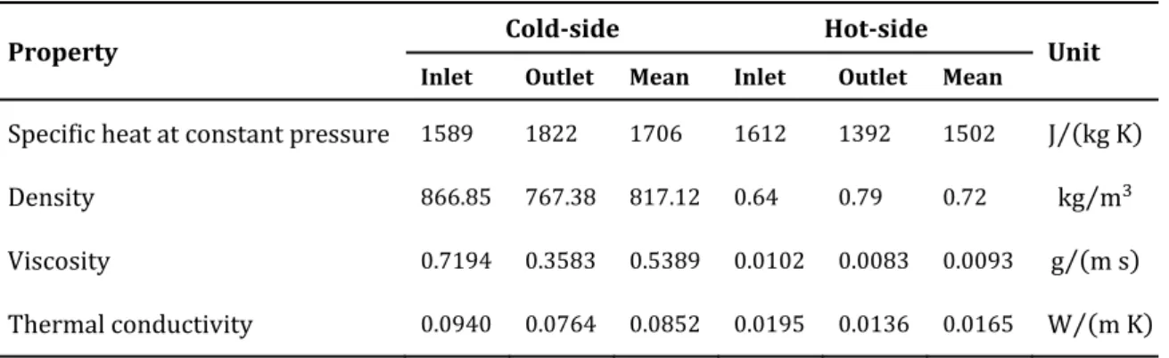
The working fluid is D4, a cyclic siloxane [6]; the physical properties of the organic fluid at inlet pressure are obtained from the NIST database through the software Aspen Properties. For each side of the MCHE, the properties are averaged with an arithmetic mean between the values at the inlet and outlet temperatures, as the pressure dependence is small enough to be neglected. The averages of interest for the case study are reported in Table 2, along the corresponding values calculated at the inlet and outlet temperatures.
Table 2: physical properties of the working fluid
Property Cold-side Hot-side Unit
Inlet Outlet Mean Inlet Outlet Mean
Specific heat at constant pressure 1589 1822 1706 1612 1392 1502 J (kg K)⁄ Density 866.85 767.38 817.12 0.64 0.79 0.72 kg m⁄ Viscosity 0.7194 0.3583 0.5389 0.0102 0.0083 0.0093 g (m s)⁄ Thermal conductivity 0.0940 0.0764 0.0852 0.0195 0.0136 0.0165 W (m K)⁄
It should be mentioned that the arithmetic averages of the specific heat at constant pressure of Table 2 satisfy almost perfectly equations (2.3) and (2.4), meaning that ,
and , are closely linear functions of the temperature. According to the
thermodynamic library employed, in the considered temperature range all the properties of interest behave likewise. If also the fluid temperature is roughly linear with the axial coordinate of the flow, the arithmetic averages of Table 2 are a suitable approximation of the real conditions inside the heat exchanger.
As pointed out in Section 1.2.3, copper and aluminium alloys are suitable candidates for microchannel heat exchanger cores. Following the guidelines of the NADCA, the alloys commercially designated as A360 and C878 are selected considering the behavior at high temperature (tensile and yield strengths after prolonged heating at testing temperature up to 260 °C; coefficient of thermal expansion; mold-filling capacity; anti-soldering to the mold). The physical properties of interest, at 20 °C since more precise data could not be found, are retrieved from [72] and are reported in Table 3.
Table 3: physical properties of the solid walls
Property A360 C878 Unit
Density 2630 8300 kg m⁄
Thermal conductivity 113 27.7 W (m K)⁄
2.2 Core Geometry
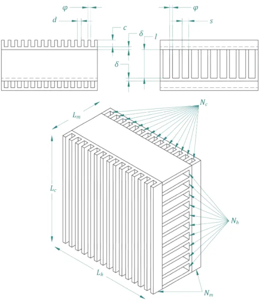
The core of the MCHE, qualitatively shown in Figure 1, comprises Nm identical modules
for the cold-side alternated with (Nm – 1) modules for the hot-side, so that the first and
the last module are at the lowest temperature possible, a common practice to minimize the heat losses to ambient [23]. Each module consists in a flat rectangular plate of thickness δ, which constitutes the dividing wall that separates the two sides, and several plain rectangular fins of thickness φ, formed directly on the plate.
When the modules are stacked up and bonded together, Nc and Nh rectangular channels
are formed between the fins of the cold- and the hot-side respectively; an additional flat plate with no fins is needed to close the module at the top of the pile. The stack length is
Lm while the channels height, width and length are c, d and Lc for the cold-side, and l, s
and Lh for the hot-side. The modules can be piled in crossflow or counterflow
configuration; however, since the required effectiveness in (2.6) is lower than 80 %, a crossflow configuration may be the best choice [23], as follows from the discussion of Section 1.3. In this case, the channel lengths on the hot- and cold-side are not necessarily equal and, together with the stack lengths, determine the dimensions of the core.
![Figure 1: sectoral trends and projections of EU GHG emissions in EU-28 [1]](https://thumb-eu.123doks.com/thumbv2/123dokorg/7447923.100805/16.892.117.731.328.734/figure-sectoral-trends-projections-eu-ghg-emissions-eu.webp)
![Figure 2: typical fuel energy dissipation in a HDV [10]](https://thumb-eu.123doks.com/thumbv2/123dokorg/7447923.100805/18.892.137.667.481.738/figure-typical-fuel-energy-dissipation-in-a-hdv.webp)
![Figure 3: fields of employment for the Rankine cycle [14]](https://thumb-eu.123doks.com/thumbv2/123dokorg/7447923.100805/20.892.112.740.407.806/figure-fields-employment-rankine-cycle.webp)