POLITECNICO DI MILANO
Department of Energy Engineering for Environmentally Sustainable World [EE-ESW]
A COMPARATIVE STUDY OF
SOLAR-HYBRID COMBINED CYCLE
SYSTEMS
Supervisor:
Dr. Paolo Silva
Simone Perini
Student number: 800603 Academic Year: 2013 - 2014ABSTRACT
The development of concentrating solar power technologies (CSP) represents an opportunity to reduce fuel dependency and greenhouse emissions. The possibility of hybridization with fossil-fuel based systems can enhance the attractiveness of CSP systems. The integration with combined cycle can provide the following benefits: high conversion efficiency, higher solar share and increased power dispatchabity.
In the present work, two different integration schemes are investigated: parabolic trough collectors are used to supply additional heat to the Rankine cycle power block in the integrated solar combined cycle scheme (ISCC). In the solar hybrid combined cycle system (SHCC), the solar energy is used to pre-heat the combustion air in the gas turbine power block. A pressurized volumetric receiver and a solar tower system are used to collect the solar radiation.
The energy, exergy and economic analysis have been performed considering a period of one year. A solar share of 35% can be achieved with the SHCC system. This value is limited to 9% in the ISCC arrangement. The net incremental solar efficiency for the SHCC plant is 20% and it is higher respect to the other system (15%) because the solar share is increased. From the exergetic point of view, the integrated solar combined cycle system seems to have higher performances than the SHCC plant: the average exergy efficiencies of the overall plant are 44.83% and 43.4% respectively. However, the variation of the exergy efficiency per unit of solar power input is higher in the case of ISCC scheme. This means that the specific exergy destruction of the solar thermal power is higher in the system using the parabolic trough collectors. Finally, the levelized electricity cost (LEC) is evaluated. The minimum electricity selling price for the SHCC and the ISCC plant are 0.05 $/kWh and 0.04 $/kWh respectively. The solar LEC for the SHCC plant is 0.08 $/kWh, lower than the 0.13 $/kWh calculated for the ISCC scheme.
In conclusion, the yearly average energy and exergy efficiency are higher for the integrated solar combined cycle and the LEC results to be lower. However,. the SHCC seems to be a promising option to integrate concentrating solar technologies and combined cycle power plant, because higher solar share and lower solar LEC can be achieved. More attention should be focused in future to develop efficient systems for the integration of the solar energy at higher temperature.
Keywords:
Concentrating solar power, gas turbines, hybridization systems, pressurized volumetric receiver, parabolic trough collector
ACKNOWLEDGEMENTS
I would like to acknowledge my supervisor Dr. Paolo Silva from Politecnico di Milano for his time and support during the preparation of this work. I thank Dr. Ossama Badr from Cranfield University for the assistance during this project. I would like to show my gratitude to Dr. Peter Turner for the help and for his competence.
I would have not been able to complete this thesis project without the presence in my life of special people and I would like to use this page to thank them all. I would like to thank my fellow students at Cranfield University: Lorenzo, Francesca, Diego, Paolo, Alessio and Luc and my flatmates Daniele and Mauro. Living together one year, we became a family. We had great time in the middle of nowhere and I wish to all of you to reach your personal goals in the future.
I have applied from the Erasmus program because of my successful Politong experience. For this reason, I would like to thank Marco, Luca, Matteo, Stefano, Andrea, Nikolas, Dario and Lorenzo for sharing hundred of moments with me in Shanghai.
I bless my friends from Cremona: Michela, Enrica, Giula(s), Lorenzo, Luca, Massimo, Riccardo and all the others. We live separated, but you proved me that friendship can overcome any distance. I have really appreciated your constant support and I am glad that people like you are part of my life.
Finally I would like to thank my family. I am indebted to our common friends whose warm affect was unwavering. I thank my aunt Ivana and cousins Michele and Nicole for their support. I am grateful to my grandparent because they have always been a constant reference point in my life.
I would like to give a special thank my parent because they have always believed in me and they gave me the strength to go forward. I thank my mum for her unconditional love.
I dedicate this work to my dad Enzo. He comforted and supported me even when I was supposed to help him. He showed me how to find hope even in the darkest moments. You were really interested in reading the first version, now this thesis is for you. Vola alto!
TABLE OF CONTENTS
ABSTRACT ... i
ACKNOWLEDGEMENTS ... ii
LIST OF TABLES ... viii
LIST OF ABBREVIATIONS ... ix
NOMENCLATURE ... ix
1 INTRODUCTION ... 1
1.1 FUNDAMENTALS OF CONCENTRATING SOLAR POWER ... 1
1.1.1 Solar Collectors ... 1
1.1.2 Receiver And Absorber ... 2
1.1.3 Transport And Storage Equipment ... 3
1.1.4 Power Conversion Block ... 3
1.2 CONCENTRATING SOLAR POWER TECHNOLOGIES AND APPLICATIONS ... 4
1.2.1 Parabolic Dish ... 4
1.2.2 Parabolic Trough Collectors ... 5
1.2.3 Linear Fresnel Reflectors ... 7
1.2.4 Solar Towers ... 8
1.3 CONCENTRATING SOLAR POWER TECHNOLOGIES COMPARISON ... 11
1.4 CONCENTRATING SOLAR POWER HYBRIDIZATION ... 12
1.4.1 Concentrating Solar Power Technologies And Combined Cycle ... 13
1.4.1.1 Integrated solar combined cycle ... 14
1.4.1.2 Solar hybrid combined cycle ... 15
1.5 AIMS AND OBJECTIVES OF THE CURRENT STUDY ... 16
2 MODELLING THE SOLAR HYBRID COMBINED CYCLE SYSTEM ... 17
2.1 MODEL DESCRIPTION ... 17
2.1.1 Pressurized Volumetric Receiver ... 17
2.1.2 Gas Turbine Power Block ... 22
2.1.3 Rankine Cycle Power Block ... 23
2.2 ENERGY ANALYSIS ... 26
2.2.1 Modelling The Solar Field ... 26
2.2.2 Modeling Of The Power Block ... 32
2.2.2.1 Compressor ... 33
2.2.2.2 Combustion Chamber ... 34
2.2.2.3 Gas Turbine ... 34
2.2.2.4 Heat recovery steam generator and rankine cycle ... 35
2.3 EXERGY ANALYSIS ... 37
2.3.1 Solar System Exergy Analysis ... 39
2.3.3 Heat Recovery Steam Generator And Rankine Cycle Exergy
Analysis ... 42
2.4 ECONOMIC ANALYSIS ... 42
2.4.1 Cost Analysis ... 43
2.4.1.1 Receiver and heliostat field ... 43
2.4.1.2 Joule-Brayton cycle components ... 44
2.4.1.3 Rankine cycle components ... 45
2.4.2 Financial Analysis ... 46
2.4.3 Levelized Electricity Cost ... 47
3 SOLAR HYBRID COMBINED CYCLE PERFORMANCES ... 49
3.1 PLANT LOCATION AND BOUNDARY CONDITIONS ... 49
3.2 PLANT SIMULATION METHODOLOGY ... 49
3.3 CYCLE PERFORMANCES ... 50
3.3.1 Nominal And Solar Hybrid Yearly Average Performances ... 50
3.3.2 Solar Related Performances ... 51
3.3.3 Monthly Average Performances ... 53
3.3.4 Economic Analysis Evaluation ... 61
4 MODELLING THE INTEGRATED SOLAR COMBINED CYCLE SYSTEM .. 63
4.1 MODEL DESCRIPTION ... 63
4.1.1 Parabolic Trough Collectors ... 63
4.2 PARABOLIC TROUGH COLLECTOR INTEGRATION IN THE HEAT RECOVERY STEAM GENERATOR ... 67
4.2.1 Energy Analysis ... 67
4.2.1 Solar Field Design ... 70
4.2.1 Exergy Analysis ... 71
4.2.2 Economic Analysis ... 72
5 INTEGRATED SOLAR COMBINED CYCLE PERFORMANCES ... 75
5.1 PLANT LOCATION AND BOUNDARY CONDITIONS ... 75
5.2 PLANT SIMULATION METHODOLOGY ... 75
5.3 CYCLE PERFORMANCES ... 76
5.3.1 Nominal and Solar hybrid Yearly Performances ... 76
5.3.2 Solar Related Yearly Average Performances ... 77
5.3.3 Monthly Average Performances ... 77
5.3.4 Economic Analysis Evaluation ... 84
6 PERFORMANCES COMPARISON ... 85
6.1 FIRST LAW EFFICIENCY METRIC COMPARISON ... 85
6.2 SOLAR RELATED METRICS COMPARISON ... 88
6.3 SECOND LAW EFFICIENCY COMPARISON ... 92
6.4 ECONOMIC ANALYSIS COMPARISON ... 94
7 CONCLUSIONS ... 97
LIST OF FIGURE
Figure 1-1 Schematic of a solar-thermal electric-power plant (Badr, 2013). ... 2
Figure 1-2 Prototypes of SG3 Big Dish at ANU Campus (Badr, 2013) ... 5
Figure 1-3 Installation of parabolic trough collector at the SEGS V, California (Badr, 2013). ... 6
Figure 1-4 The collector field of the German/Spanish Direct Solar Steam (DISS) project (Badr, 2013). ... 7
Figure 1-5 The 30 MW PE 2 solar plant at Calasparra, Murcia, southern Spain (Badr, 2013). ... 8
Figure 1-6 The Beam-down solar concentrator in Masdar City, Abu Dhabi, UAE (Badr, 2013). ... 9
Figure 1-7 The 24 GW Planta Solar (PS10) in Spain (Badr, 2013). ... 11
Figure 1-8 Solar hybrid combined cycle integration options (Kribus et al., 1998). ... 13
Figure 2-1 Solar hybrid combined cycle diagram ... 18
Figure 2-2 Refros receiver module (Buck et al., 2002) ... 18
Figure 2-3 Solgate receiver cluster. a) receiver aperture area b) solar cluster final layout (European Commission 2005). ... 20
Figure 2-4 Schematic view of the low temperature module ( European Commission, 2005). ... 20
Figure 2-5 SHCC bottoming Rankine cycle power block diagram ... 25
Figure 2-6 Receiver enclosure ... 29
Figure 2-7 Cosine effect (Turner, 2014) ... 31
Figure 2-8 Sun image and minimum beam diameter (Turner, 2014) ... 31
Figure 3-1 Electrical power output SHCC plant ... 53
Figure 3-2 solar hybrid combined cycle electric power output, 14th April ... 54
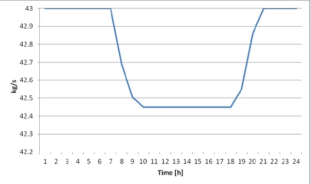
Figure 3-3 Flue gases mass flow rate, 14th April ... 55
Figure 3-4 Components Mass fractions in flue gases, 14th April... 55
Figure 3-5 Enthalpies of the flue gases at the inlet and outlet section of the turbine, 14th April ... 56
Figure 3-6 Polytrophic index for the flue gases, 14th April ... 56
Figure 3-8: SHCC Exergy Efficiency ... 58
Figure 3-9: Fuel consumption ... 59
Figure 3-10: solar share ... 59
Figure 3-11: Net incremental solar efficiency. ... 60
Figure 3-12 Co2 avoidance ... 60
Figure 3-13 Component capital costs for the solar hybrid combined cycle ... 61
Figure 4-1 Integrated solar combined cycle diagram ... 64
Figure 4-2 Euro-Trough system: a) Supporting structure sketch, b) Test facility (Lupfert et al, 2001). ... 65
Figure 4-3 Schott receiver (Passoni et al., 2010) ... 67
Figure 4-4 Solar system integration for the ISCC plant ... 68
Figure 5-1: Integrated solar combined cycle monthly power output ... 78
Figure 5-2 Steam mass flow rate in the Rankine cycle power block for the ISCC system for the 14th of April ... 79
Figure 5-3 Temperature profile in the HRSG for the 14th of April at different hours... 80
Figure 5-4: Monthly average energy efficiency ... 80
Figure 5-5: Monthly average exergy efficiency ... 81
Figure 5-6: Parabolic trough collectors efficiency ... 82
Figure 5-7: Monthly average solar share ... 82
Figure 5-8: Monthly average incremental solar efficiency ... 83
Figure 5-9: Monthly average CO2 avoidance ... 83
Figure 5-10 Components capital cost for the integrated solar combined cycle 84 Figure 6-1: Monthly average electric output power ... 86
Figure 6-2: Monthly average fuel thermal input ... 86
Figure 6-3: Monthly average solar input ... 87
Figure 6-4: Monthly average energy efficiency ... 87
Figure 6-5: Monthly average solar share ... 89
Figure 6-6: Net incremental solar efficiency, ηref= 60%. ... 90
Figure 6-9: Monthly CO2 avoidance, ηref= 50.29%... 92
Figure 6-10: Monthly average exergy efficiency ... 93 Figure 6-11: Levelized electricity cost and solar levelized electricity cost. ... 95
LIST OF TABLE
Table 2-1 Pressurized receiver cluster specification ... 22
Table 2-2 Gas turbine parameters. ... 23
Table 2-3 Rankine Cycle Parameters ... 25
Table 2-4 Pressurized volumetric receiver cost (European Commission, 2005) ... 44
Table 3-1: Nominal and yearly average performances for the SHCC plant ... 50
Table 3-2 Solar related yearly average performances for the SHCC plant ... 52
Table 4-1 Value of the constants used to compute the overall efficiency of the parabolic trough collectors. (Franchini et al., 2013) ... 69
Table 5-1 Yearly average solar-hybrid and nominal performances of the ISCC system ... 76
Table 5-2 Solar related yearly average performances for the ISCC system ... 77
Table 6-1 Solar related evaluation metrics results ... 88
Table 6-2 Annual average exergy efficiency... 93
Table A.1 Matlab code numerical results ... 107
LIST OF ABBREVIATION
ANU Australian National University CC Combined cycle
CSP Concentrating solar power
DIAPR Direct Irradiation Air Pressurized Receiver DISS Direct Solar Steam
DLR Deutsches Zentrum fur Luft und Raumfahrt (Germa Aerospace Center) DSG Direct steam generation
EUD Energy utilization diagram HCE Heat collection element
HFLCAL Heliostat Field Layout Calculator HRSG Heat recovery steam generator HT High Temperature
IEA International Energy Agency IRR Internal rate of return
ISCC Integrated solar combined cycle ISO International organization for Standard LEC Levelized electricity cost
LFR Linear Fresnel reflector LT Low Temperature MT Medium Temperature NPV Net present value
NREL National Renewable Laboratory ORC Organic Rankine cycle
PCM Phase change materials PDC Parabolic dish collector ppi Pores per inch
PTC Parabolic trough collector
S&L Sargent and Lundy Consulting Group SCOT Solar Concentration Off Tower SEGS Solar Energy Generation Station SES Sterling energy system
SHCC Solar hybrid combined cycle STP Solar tower power
TIT Turbine Inlet Temperature
NOMENCLATURE
A Area m2
& O M
c Specific cost for plant maintenance $/kWh
CF Cash Flow $
p
c Specific heat capacity at constant pressure J/kg K p
c Molar specific heat capacity at constant pressure J/kmol K
v
c Specific heat capacity at constant volume J/kg K
d distance of the first row of heliostats from the solar tower m
D Diameter m
DNI Direct normal irradiation W/m2
f h
Enthalpy of formation J/kmol
E Electrical power W
eff Effectiveness -
f Receiver convective heat loss factor - 2
CO
f carbon dioxide emissions per fuel heating rate kgCO2/MJ P
f Pressure coefficient -
T
f Temperature coefficient -
view
F Radiation view factor -
h Enthalpy J/kg
H Convective heat transfer coefficient W/m2 K
h Enthalpy J/kmol
I Incident Flux kW/m2
k Polytrophic index -
K Solar angle modifier -
L Heliostat field length m
LHV Lower heating value J/kg
m Mass flow rate kg/s
m Interest rate -
MM Molar mass kg/ kmol
n Years -
n Molar flow rate kmol/s
gen
S Entropy generation rate W
s Entropy J/kg K
T Temperature K
t
Solar tower height mW Mechanical power W
X Solar share -
x Molar fraction -
x Physical exergy rate W
T Temperature variation K
P Pressure variation bar
Heliostat field density - Exergy destruction rate W
Absorbitivity -
Pressure ratio -
emissivity -
Solar incident angle rad
I
Energy efficiency -II
Exergy efficiency -_ _
net incr sol
Net incremental solar efficiency -
Waste boiler economic analysis coefficient W/ K Air/fuel ratio -
Carnot coefficient -
Density kg/m3
Stefan-Boltzmann constant W/m2 K
Waste boiler heat loss coefficient -
Specific chemical exergy J/kg
Subscripts
AC Air compressor
cond Condenser
fg Flue/ exhaust gases
field Solar field
GT Power gas turbine
HTF Heat transfer fluid
HTX Heat exchanger
is Isentropic process
rec Receiver
ref Reference plant
1 INTRODUCTION
Solar energy offers a clean, accessible and inexhaustible energy resource. The highest solar potential is found in the so called Solar Belt, the ground surface comprised between 15° and 35° latitude. According to the IEA (2011), in a future carbon-constrained scenario, solar thermal energy together with solar photovoltaic energy could provide up to 25% of global electricity by 2050.Therefore, sun-derived power generation is an excellent way to reduce fossil fuel dependency representing at the same time the opportunity to achieve the international commitment of CO2 reduction (Barigozzi et al., 2012). Among
the different options for harnessing Sun's power, Concentrating solar power (CSP) technologies present specific benefits such as the centralized large scale electricity production, the economy of scale and the possibility of thermal storage integration (Paolo Silva, 2013).
The Technology Road Map of the International Energy Agency (IEA, 2010) predicted that CSP plants would provide 148 GW in 2020. However, the same institution (IEA, 2012) forecasted that the global installed capacity of solar thermal power-generation will reach only 11 GW by the end of 2017, a much lower value than the Agency and the industry have anticipated earlier. The increased competition from solar photovoltaic systems and the inability to reduce electricity generation cost through economies of scale were the factors affecting the CSP development. However, the possibilities of employing thermal storage and the hybridization with fossil fuel-fired plants could enhance projects attractiveness.
1.1 FUNDAMENTALS OF CONCENTRATING SOLAR POWER
Concentrating solar power plants consist of four different sub-systems: solar collectors, receiver and absorber, transport and storage equipment and power conversion block.
1.1.1 Solar Collectors
The collector captures and concentrates direct normal incident solar radiation (DNI) onto the receiver. In general, collectors are reflective surfaces (for a heliostat field of a central receiver system) or parabolic mirrors in case of parabolic though and parabolic dish systems. These mirrors follows the apparent sun path using a single or two axes tracking devices and they focus the beams onto the absorber (Barlev et al., 2011).
Figure 1-1 Schematic of a solar-thermal electric-power plant (Badr, 2013).
1.1.2 Receiver And Absorber
The receiver is a heat exchanger that absorbs the concentrated radiation and transfer the thermal power to a working fluid.
Distributed receivers are irradiated by dedicated concentrators and heat locally a heat transport fluid. A large number of collectors are needed. In point focus systems the receivers are located at the central point of the parabolic dish collectors, while the absorbers are placed along the focal line of parabolic collectors in a line focus plant.
In central receivers systems, the heliostat field concentrates the radiation onto a single absorber at the top of a tower. The main advantages of this technology are:
single receiver;
higher concentration ratio;
possible exploitation of economy of scale.
Different kinds of central receivers have been developed: cavity receivers operate with tubes lining the walls of a cavity on top of the tower, whereas in external receivers tubes are placed on the outside surface. Section 1.2 explains the specific receiver installed in the different CSP schemes.
1.1.3 Transport And Storage Equipment
The energy exchange from the working fluid to the power conversion unit is regulated by the transport-storage system. Fans or pumps are needed to circulate the working fluid in the system. In some solar-thermal plants, a portion of the thermal energy is stored for later use. Due to the cyclic and random nature of the solar radiation, three kind of thermal storage are necessary for maintaining a constant supply of solar thermal power:
Very short-term storage: small storage system to avoid transient period when sun is temporarily covered by clouds. Usually the storage capability is 30 minutes;
Short-term storage: the excess energy harvested during the day is saved to allow the plant operations during the night;
Long-term storage: part of the higher energy flux collected in spring and summer is stored to support the limited radiation during cold seasons. Long term storage systems have not been proved yet at large scale. Thermal energy storage can be implemented according to the following strategies (Barlev et al., 2011):
Sensible heat storage: a solid or a liquid material or the working fluid itself is heated and it is insulated from the environment. Reinforced concrete, solid sodium chloride and silica fire bricks can be used as indirect solid storage medium. Usually the heat transfer fluid is in liquid phase and can be directly stored. Mineral oil, synthetic oil, silicone oil, molten nitrate, molten nitrite and carbonate salts are sensible heat storage liquids.
Latent heat storage: solid liquid phase change can be used to reserve energy. Phase change stores a great amount of thermal energy, and can be utilized for night time energy storage. A large number of Phase
change materials (PCM) have been investigated as storage systems due to the potential high efficiency. However, the pressure drop required affects the performances of the power system. Organic and inorganic compounds have being studied because PCM have typically low thermal conductivity and slow heat exchange rate (Barlev et al., 2011).
Chemical storage: solar thermal energy can be used in reversible synthesis/de-synthesis endothermic/ exothermic reactions. Reformation of methane and CO2, metal oxide/metal conversions and ammonia
synthesis/dissociation are heat-assisted chemical reactions that can be exploited. Chemical storage is the most suitable energy saving system for long-term or seasonal storage (Barlev et al., 2011).
1.1.4 Power Conversion Block
The power-conversion system consists of a heat engine, coupled to an electricity generator. A secondary conventional fossil-fuel-driven heat source
can be installed as back-up system to supply the power unit when radiation is unavailable or limited.
Different thermodynamic cycles can be integrated with solar thermal power plants:
Rankine-cycle systems, using steam or other suitable working fluids;
Brayton-cycle systems using Helium, CO2 or air as the working fluid;
Combined-cycle systems;
Stirling engines.
It is noteworthy to highlight that CSP systems might not be exclusively used to generate power, but they can be applied to industrial heat processes, chemical production, water desalination, heating and cooling devices.
1.2 CONCENTRATING SOLAR POWER TECHNOLOGIES AND APPLICATIONS
Nowadays four CSP technologies have been developed: Parabolic dish systems, Parabolic trough collectors, linear Fresnel reflectors, and Solar power towers (Zhang et al., 2013).
1.2.1 Parabolic Dish
The sunrays are concentrated at the focal point supported above the center of the dish in parabolic dish collector (PDC).Usually in point focus collectors, an open cavity receiver is placed at the focal point of a parabolic mirror, but external receiver could be used due to the high concentration factor (100 -1000 suns). Parabolic dish plants show the highest solar to electricity efficiency among the CSP technologies, but they are not compatible with thermal storage and hybridization. The simplicity of the system seems feasible for mass production, but the low power capacity limits the development of this technology. Dish systems are commonly coupled with sterling engines for power generation.
The first pilot plant was the Solar Total Energy Project built in 1982 in Georgia (USA). The world’s largest solar concentrating parabolic dish is the SG3 Big Dish, a prototype plant installed in 1994 at the Australian National University (ANU), in Canberra. With a 400 m2 hexagonal aperture area, the plant was able to provide some 60 MWh of electricity to the local grid over the period 1996-2000 (Figure 1.2). The company Sterling Energy Systems (SES) developed the SunCatcher , a commercial dish-Stirling engine system for the deployment in large utility-size grid connected fields (Greenpeace International, 2009). Based on this technology, SES planned to build two different parabolic dish plants in California (NREL, 2013):
The Calico-Solar One was designed to generate a total power of 850 MW exploiting 34000 SunCatcher dish system. The installation of the first 575 MW should be completed by 2014.
The Imperial Valley-Solar Two, a 30000-SunCatcher dish system with a total power output of 750 MW.
Figure 1-2 Prototypes of SG3 Big Dish at ANU Campus (Badr, 2013)
1.2.2 Parabolic Trough Collectors
In Parabolic trough collector a group of curved reflectors focus the sunrays onto the absorber. The mirrors are composed of sheet of reflective material (low iron glass) bent into a parabolic shape. The receiver is a metal tube with evacuated glass covering, mounted along the focal line of the linear array. A coated glass pipe encloses a black metal pipe to limit heat loss by convection and to allow the transmissivity. The metal tube is covered with selective coating to increase solar absorbance and reduce the emittance. Thermal oil is commonly used as heat transfer medium, but water is employed in direct steam generators. This system can operate at relatively low maximum temperatures usually 400°C for oil or up to 550°C for direct steam generators. The latter system presents technical challenges due to the high pressure involved in boiling and the annual average solar-to-electricity conversion efficiency is about 15% for current designs (IEA, 2011). Parabolic though collectors can be also employed to provide thermal power to industrial processes.
Solar Energy Generating Stations (SEGS) were the first commercial plants. They were built in California between 1981 and 1991providing 12TWh of electricity up to 2004.
The Direct Solar Steam (DISS) facility was installed in 1998 to test the direct generation of high-temperature and high-pressure steam in the absorber tubes. The eleven, 550m long modified Luz parabolic trough collectors (LS-3) proved the feasibility of the direct steam generation under real solar conditions in more than 4000 hours of operation. The largest plant using parabolic trough collectors is NOOR I located in Morocco. The beginning of operations is planned to be in 2015, when the system will be able to generate 160 MW of power. Parabolic-trough systems represented about 95% of all facilities in operation globally at the end of 2011 and 75% of plants under construction by mid-2012 (NREL, 2013).
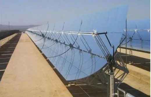
Figure 1-3 Installation of parabolic trough collector at the SEGS V, California (Badr, 2013).
Figure 1-4 The collector field of the German/Spanish Direct Solar Steam (DISS) project (Badr, 2013).
1.2.3 Linear Fresnel Reflectors
Linear Fresnel reflectors (LFR) approximate the parabolic shape of the trough systems by using long rows of flat or slightly curved mirrors to reflect the radiation onto a downward facing linear receiver. Linear Fresnel systems are less capital intensive than parabolic though and they are usually employed as steam generators, since the receiver is fixed and a higher pressure is allowed. However this technology has a lower efficiency and it is difficult to install a thermal storage.
The first LFR prototype was installed in Liege in 2009. Solar Heat and Power Pty Ltd, the University of Sydney and the University of New South Wales developed the first commercial concentrating linear Fresnel array for supplying about 10 MW of thermal energy to feed-water heaters of the steam cycle of the 2 GW Liddell coal-fired power station in New South Wales, Australia. The 1.4 MW Fresnel solar power demonstration plant Puerto Errado 1 (PE 1) was installed at Calasparra (Spain) in March 2009 by the German company Novatec Solar. The plant is capable of producing 2 GWh of electricity annually. In 2010 the same company built the utility-scale 30 MW linear Fresnel plant Puerto Errado 2 (PE 2 , see Figure 1.5). The plant went into operation in August 2012 and produce 49 GWh of electricity in one year. The most recent installation is the 100MW Dhursar plant in India (expected to start operation in May 2013). Kogan Creek Solar Boost Project, currently under construction in Australia is expected to be the largest solar integration with a coal-fired power station in the world when it will be completed in 2014 (NREL, 2013).
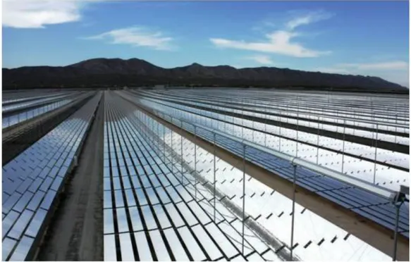
Figure 1-5 The 30 MW PE 2 solar plant at Calasparra, Murcia, southern Spain (Badr, 2013).
1.2.4 Solar Towers
Solar power towers (SPT) are central receiver systems that use a heliostat field collector. Heliostats are usually flat or slightly concave mirrors that follow the sun by two axis tracking. In the central receiver on the top of the tower, concentrated solar radiation is absorbed by a heat transfer fluid (water, molten-salt, thermal fluid or air). However, The Weizmann institute developed the Solar Concentration Off-Tower (SCOT), also named Beam-down system. A tower-mounted secondary hyperboloid mirror redirects the concentrated solar beams downwards towards a lower focal region near ground level. A SCOT solar concentrator was recently built in Masdar, Abu Dhabi in 2013 (Mokri et al., 2013).
There are different kinds of central receiver: external tubular, cavity tubular and volumetric. Tubular systems are more appropriate for boiling processes, while volumetric receivers have been tested for high temperature applications. Porous structure increase the transfer surface and gas fluid such air with low heat transfer coefficient can be used.
Central receiver can be classified according to the working fluid used or absorber coolant: this could be liquid, gaseous or solid (Ho and Iverson, 2014).
Figure 1-6 The Beam-down solar concentrator in Masdar City, Abu Dhabi, UAE (Badr, 2013).
Liquid receiver can be organized in two classes:
Liquid tubular receivers are composed of an array of thin-walled tubes (stainless steel or alloyed) that force the working fluid (water/steam or molten salt) in multiple passes through incident concentrated sunlight.
Gravity force drives the fluid in falling-film receivers. The coolant flows along an inclined wall while it is irradiated, reducing the pumping work. Water/steam receivers were first investigated since1981 (Aringhoff, 2005). Sodium and Nitrate salt were analyzed as working fluid, but more recently prototypes of air receivers have been developed.
Receiver that employ a gaseous coolant are subdivided in:
volumetric air receivers: A porous structures, usually honeycombs or porous ceramics is used as absorber and the air that flows through the material is heated up to 1500°C when Silica carbide is used.
submicron carbon particles are suspended in pressurized air and heated by concentrated sunlight in particle air receiver design.
tubular receivers have been designed and tested by DLR for application in the order of 100 kW-1MW. The multi-layer pipes consist of Inconel material with copper sandwiched in between. The hydro-forming process enhances the heat transfer and distribution. Tubular receivers that
employ supercritical CO2 as heat transfer have been studied because of
the growing interest in supercritical-CO2 Brayton cycle.
TSA-PHOEBUS project was the first one employing a volumetric receiver in 1993. In 1998 the Weizmann Institute introduced the first pressurized volumetric receiver. The Direct Irradiated Air Pressurized Receiver (DIAPR) consists of a high-pressure fused silica window and a compact ceramic volumetric absorber, capable of heating compressed air at 20 bar to about 1200°C (Kribus et al., 1998). In 2008, the Julich Institute and the German Aerospace Centre (DLR) tested a receiver cooled by ambient air that supply a 11.5 MW water-steam power cycle (DLR, (2009)). Finally, solid particle receivers were investigated to increase the receiver outlet temperature to over 1000°C exploiting the storage capability of the solid particles. In this kind of receiver, sand-like ceramic particles are heated by direct radiation falling through a cavity. Thermal stresses due to high temperature and high pressure fluid can be avoided (Ávila-Marín, 2011).
The first solar tower commercial plant was the Planta Solar (PS10) in Spain (Figure 1.7). It began operation in 2007, designed to produce 24 GWh. Ivanpah Solar Power Generating Station is most recent solar tower installed and it started operation at the beginning of 2014. This plant consists of three units for a total installed capacity of 392 MW and it is expected to produce 1.08 TWh of energy every year (NREL, 2013).
The integration of CSP systems into high efficiency thermodynamic cycle has been studied in the literature. Dunham et al.(2014) discussed the application of a Solar Power Tower to different power generation system (He-Brayton, regenerated CO2-Brayton, CO2-recompression Brayton, steam Rankine, and
CO2–ORC combined cycle) and showed that the steam Rankine cycles achieve
the best thermal efficiency. Previous investigators focused their studies on thermodynamic or exergonomic optimization of central receiver applied to combined cycle. In particular, thermo-economic optimization has been done about green-field totally solar driven heliostat solar towers (Spelling et al., 2009 & 2012)
Figure 1-7 The 24 GW Planta Solar (PS10) in Spain (Badr, 2013).
1.3 CONCENTRATING SOLAR POWER TECHNOLOGIES COMPARISON
Advantages and disadvantages of the different CSP technologies must be evaluated according to the size, the location, the purpose and the budget of the specific project (Barlev et al., 2011).
Parabolic trough collectors are the most mature technology within the commercial CSP plants. PTCs are well-tested systems and they can be coupled to fossil fuel or geothermal energy sources. Synthetic oils are the most used option as heat transfer fluid, but they are expensive to manufacture and they cannot be used in high temperature systems such as solar towers. Steam can be used as working fluid but Fresnel collectors are preferable in this case. Furthermore, the operating temperature in PTC is usually around 400°C, making this technology more suitable for industrial process integration rather than for power generation. The low temperature achieved by the working fluid is partly related to the limited concentrating ratio of PTC (up to 80 suns). Increasing the solar radiation concentration, higher working temperatures and better thermodynamic efficiencies can be achieved. In solar tower power plants, very high temperatures (up to 2000°C) are reached since the amount of irradiation focused on a single receiver is larger (200–1000 kW/m2). Thus the system can operate very efficiently using complex energy conversion cycles, such as the combined cycle (Zhang et al., 2013). The reduction of heat losses and the simplification of heat transport can reduce costs (Zhang et al., 2013). In addition, the solar tower scheme can be coupled to all three thermal storage methods discussed, increasing the attraction of investors in comparison with other CSP systems. Nevertheless, the cost for the heliostat field and the receiver are still too expensive to be competitive in the market (Barlev et al., 2011).
1.4 CONCENTRATING SOLAR POWER HYBRIDIZATION
Fossil fuel back-up systems are usually installed in parallel with CSP technologies in order to supply thermal power when the sun is not available or the collected power is not sufficient due to lower irradiation. However, the utilization of such plants is limited and in order to improve utilization factor hybrid systems or thermal storage can be exploited. Hybridization of solar plants allows the use of both solar energy and fossil fuels concurrently. Issues and advantages of the hybridization of solar thermal power in electricity generation was reviewed, described, and analyzed by Williams et al.(1994). Four options for hybridization have been compared:
Redundant system hybridization: two independent power plants are constructed, one fossil-fired and one solar-heated. The main disadvantage is the cost related to electricity redundancy, but the different heat engines can be optimized in the proper temperature range and a greater flexibility is ensured;
Parallel fossil/heater hybridization: a fossil energy source is used in parallel with solar heater to supply a common input to the power block. The sources are at different temperatures and the working fluid is mixed prior to enter the heat engine, increasing the exergy destruction. In this case, the overall conversion efficiency of the Rankine cycle changes as the relative make-up of the solar and natural gas generated steam change. SEGS VIII and IX plants with parabolic trough collectors exploit this strategy;
Augmented hybridization: Solar thermal power can be used as an augmentation of the fossil fuel source. In this case, the solar heat is input through only a portion of the thermodynamic cycle. The most significant benefit of this approach is that the temperature of the solar heater and the fossil -fuel burner no longer need to match. Integrated solar combined-cycle systems use this approach;
Solar preheat hybridization: the fossil-generated heat provides temperature topping. In this approach, energy from fossil fuel combustion is used to raise the temperature of the working fluid that has previously been heated using a CSP technology, to match the thermal level required by the heat engine. The lower the temperatures difference between the sources, the higher the efficiency. Due to the high temperature involved, solar towers are preferred as CSP technology in this case.
Furthermore, Jamel et al. (2013) proved that the advantages of hybrid plant over solar only installations include:
the opportunity for higher energy conversion efficiency;
lower capital investment in new technology;
higher valued energy due to dispatchability;
lower energy cost.
fluctuating price of the fossil fuels affects the economic return of the solar investment. For this reason, only green field systems are considered.
In order to increase the power production and dispatchability and at the same time reducing the energy costs, the hybridization with high efficient cycles and the integration with thermal storage must be considered for solar tower.
1.4.1 Concentrating Solar Power Technologies And Combined Cycle
The potential of the integration of CSP systems and combined cycle is the possibility to:
achieve the highest possible conversion efficiency;
supply solar heat at the highest temperature and to reach the largest possible solar share (at design conditions);
hybrid operations, to provide dispatchable full capacity at all times. Two options have been studied to exploit solar radiation in combined cycle:
The thermal power harvested from the concentrated solar radiation is supplied to the compressed air in the Joule-Brayton cycle. The proposed layout of the plant is illustrated in Figure 1.8 Option II.
The steam in the bottoming cycle is generated using the solar radiation captured by the collector system (see Figure 1.8 Option I).
1.4.1.1 Integrated solar combined cycle
Solar energy from a parabolic-trough field can be integrated with a combined-cycle power plant to increase its efficiency. The concept of the integrated solar -hybrid CC power plants started in the early 1990s, initially proposed by Luz Solar International as a means of integrating PTCs with modern combined cycle power plants.
In an Integrated Solar Combined Cycle (ISCC), the solar heaters supply energy to the bottoming Rankine cycle of a combined cycle. Generally, there are two kinds of ISCC schemes: thermal oil systems and steam systems.
In one of the schemes, thermal oil is used as heat transfer fluid in the parabolic trough solar field. The solar thermal power is used to evaporate part of the high pressure steam. The flue gases are used to pre-heat the feed- water and to superheat the steam. HRSG are generally designed with one or two pressure levels. Steam turbine, pre-heater, super-heater and condenser of an ISCC have to be larger than the corresponding parts of a CC plant using the same gas turbine type because of the increased steam mass flow for the integrated plant. Allani et al. (1997) evaluated the feasibility of the implementation of a pilot plant in Tunisia, using the thermo-economic optimization approach. They found that the ISCC system showed several advantages compared with a purely solar steam cycle or any of the various other hybrid solar concepts existing at that time. Dersch et al. (2004) proved that ISCC plants show lower specific CO2 emissions than optimized CC plants if properly designed and
operated and they perform better than pure solar parabolic though collectors (as SEGS plants) considering 24-hours operation a day and no thermal storage. Horn et al. (2004) analyzed the technical and economic aspects of an ISCC plant to be implemented in Egypt. In this case, they compared two types of solar system for the integration: PTC field and volumetric air receiver tower. They demonstrated that both parabolic trough collectors and volumetric receiver had a positive impact on the ISCC system.
Direct Steam Generation (DSG) parabolic trough solar collector can be coupled with the bottoming steam cycle and the feed-water is directly evaporated in the solar field. Employing DGS trough, low irreversibility at the heat recovery steam generator and high system thermal efficiency were obtained. Recently Li et al. (2014) demonstrated that a two pressure stages ISCC with direct stream generation can achieve a fossil fuel saving ratio of 23.6% with solar share of 27.8%. Franchini et al. (2013) proved that the solar power production and the solar-to-electric efficiency are higher in ISCC coupled with a solar tower field because the combined effect of the higher solar tower collection efficiency and the higher CC conversion efficiency.
The first ISCC was installed in Italy in 2010. The plant employ molten salt (sodium and potassium nitrate) as the heat transfer fluid in the solar field and as heat storage medium.
(NREL, 2013). Most of the CSP projects in the Middle East and North Africa are integrated solar-combined cycle power plants (NREL, 2013).
1.4.1.2 Solar hybrid combined cycle
Solar energy input at high temperature could be an efficient heat source for driving a combine cycle power plant. The development of collector with elevated concentration ratio and high temperature receiver allows the solar radiation to preheat the working fluid in the gas turbine. Experimental studies and analytical simulations have proved that the increase in efficiency offsets the high initial investment required for this solar application, resulting in a more effective solar electricity generation system (Schwarzbözl et al., 2006). The major advantages of solar gas turbine systems compared to other solar-fossil hybrid power plants are the high solar shares with high conversion efficiencies. Solar shares of 40%up to 90% can be realized in the design case and annual solar shares up to 30% can be achieved in base load. The conversion efficiencies of the solar heat can vary from around 40% up to more than 50%, using modern gas turbine systems (with recuperator or combined cycle mode) (Schwarzbözl et al., 2006). Kribus et al. (1998) analyzed the performances of a SCOT/CC hybrid plant. Employing the beam down collector that focused the solar radiation on a multistage DIAPR receiver, they demonstrated that this technology offers the potential for high performance and low installed cost and levelized electricity cost.
Solar preheating at the topping Brayton cycle was proposed by Bohn et al. (1995). They showed that this scheme offers high conversion efficiency but limited solar contribution to the plant’s overall electricity production. Price et al. (1996) proposed a hybrid solar tower system using high concentration optics and high temperature air receivers to drive the CC power plant. They analysed the solar energy use at a high exergy level as a heating source for the topping GT cycle. Kolb (1998) examined the economic potential of using different configurations of hybrid and solar-only tower power plants. Results showed the hybrid plants are more economical compared with solar only power plants for solar tower integrated to combined cycle and coal-fired power plants. More recently, Heide et al. (2010) proposed a new configuration of CC with solar tower. The solar heat directly feed the gas turbine between the compressor outlet and the combustor inlet, increasing the solar share. They named this alternative configuration Solar Hybrid Combined Cycle (SHCC).
Solar-hybrid gas turbines with combined cycle systems shows interestingly low expense for moderate power level in centralized electricity generation. Cost comparable with ISCC plants can be achieve with a smaller system (16 MW instead of 310 MW) and with a significantly higher solar share (28% instead of 9%). Small-scale plants (<5–10 MW) should be applied in distributed markets using cogeneration to be economically feasible (Schwarzbözl et al., 2006). Solar hybrid gas turbines have a high potential since they present high efficiency power conversion systems and the advantages of hybrid power
plants: variable solar share, fully dispatchable power, 24 hours operation without storage. This could be an important step towards cost reduction of solar thermal power.
1.5 AIMS AND OBJECTIVES OF THE CURRENT STUDY
In the present work the integration of concentrating solar energy technologies with combined cycles is assessed. The aim of this thesis is to analyze and compare the performances of two different integration schemes: the solar hybrid combined cycle system, described in Chapter 2 and the integrated solar combined cycle plant (Chapter 4). Parabolic trough collectors are used to supply additional heat to the Rankine cycle power block in the ISCC scheme. In the SHCC arrangement, the solar energy is used to pre-heat the combustion air in the gas turbine power block. A pressurized volumetric receiver and a solar tower system are used to collect the solar radiation.
The energy and exergy efficiencies and the levelized electricity cost of the two systems are compared in order to evaluate the advantages and disadvantages of the different arrangements (Chapter 6). The comparison is aimed to identify critical issues related to solar energy integration with combined cycle power plants and to specify the most significant points to be developed in future works.
The following steps will be covered to reach the final objective:
Implement a mathematical model for the SHCC and perform the energy and exergy analysis of the system.
Define the total costs and the levelized electricity cost of the plant.
Develop the mathematical model for the ISCC system to evaluate the energy and exergy efficiency;
Determine the total cost and the levelized electricity cost for the considered ISCC power plant;
Compare the performances of the SHCC plant with the ones of the ISCC systems to define the future development needed to achieve the best integration of combine cycle with concentrating solar power technologies.
2 MODELLING THE SOLAR HYBRID COMBINED CYCLE
SYSTEM
2.1 MODEL DESCRIPTION
A diagram of the solar hybrid combined cycle considered in this study is represented in Figure 2.1. The plant consists of a heliostat field, a solar tower equipped with a pressurized volumetric receiver, a gas turbine and a heat recovery steam generator which supplies thermal energy to a steam Rankine-cycle power system.
The heliostats concentrate the solar radiation onto the aperture area of the volumetric receiver where pressurized air is pre-heated. A detailed description of the pressurized volumetric receiver is given in Section 2.1.1. The pre-heated air enters the combustion chamber of the gas turbine, where fossil fuel burns to provide the energy necessary to reach the rated turbine inlet temperature. The gas turbine generates the power from the expansion of high pressure and temperature gases and the thermal energy available in the exhaust gases is recovered in the waste heat boiler or Heat Recovery Steam Generator (HRSG). Refer to Chapter 2.1.2 for specific information related to the gas turbine system. Finally, the steam generated in the HRSG runs the bottoming Rankine cycle. The assumptions and the parameters selected for the design of this part of the system are reported in Section 2.1.3.
2.1.1 Pressurized Volumetric Receiver
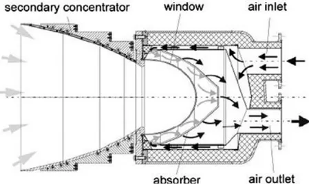
The German Aerospace Center (DLR) and its partners have developed a prototype of pressurized volumetric receiver to demonstrate the feasibility of introducing solar energy into the gas turbine of combined cycle power generation systems (Buck et al, 2002). They first developed the Refros volumetric receiver: it consists of a secondary concentrator mirror coupled with a pressure vessel where the absorber material is located. A domed quartz window was selected to separate the ambient from the pressurized chamber. Figure 2.2 represents a schematic diagram of the Refros receiver. The secondary concentrators were introduced to increase the radiation flux incident on the absorber. Increasing intensity of the incident solar energy allows the air to reach a higher temperature. In the first prototype the absorber was made of several layers of heat-resistant wire screens (Inconel 600).
Figure 2-1 Solar hybrid combined cycle diagram
Starting from 1996, theoretical analysis and experiments have been carried out to evaluate the performance of the secondary concentrator and to demonstrate the thermal efficiency and the reliability of the system. The tests proved that by modifying the shape of the secondary concentrator, the optical efficiency of these elements can be improved to 86% (Buck et al, 2002). During the experiments in 2002 in the CESA-1 tower facility in Plataforma Solar de Almeria (Spain), for the first time a pressurized volumetric receiver withstood an input thermal capacity up to 400kWth at 15bar without damage. One important advantage of this system was the low pressure drop achieved (18 mbar only) (Heller 2006; Ho and Iverson 2014). Problems related to the degradation of the window surface arose even though these tests were short compared to lifetime requirements.
Many studies have focused on the possibility to integrate CSP technologies to industrial gas turbines systems. Among these, the European Commission funded the Solgate project started in 1998 with the main goal of developing a solar receiver cluster able to provide pressurized air at 1000°C to feed a conventional gas turbine. The pressurized solar receiver system consisted of three 400 kWth Refros modules. Each element was equipped with a secondary
concentrator. The modules had a hexagonal aperture and were connected in series (Figure. 2.3(a)). The low temperature receiver (top module in Figure 2.3(b)) was developed in order to decrease the overall cost of the receiver employing cheaper material for the first heating stage. In this case a multi-tube coil was employed in combinations with the secondary concentrator (Figure 2.4). The optimized layout consists of 16 tubes connected in parallel, each with a length of 2.3 meters and a diameter of 28 millimeters. This concept was selected to reduce mechanical stresses and increase the heat transfer coefficient ensuring higher performances. The medium temperature receiver and the high temperature modules (in the middle and at the bottom of Figure 2.3(b) respectively) have the structure of the Refros pressurized volumetric receivers. In the high temperature receiver the metal-wire absorber was replaced with a ceramic one in order to meet the target temperature (1000°C). The ceramic absorber was made of silicon carbide (SiC) with 20 ppi porosity coated with a silica layer and tempered to increase absorbitivity to 96%. The geometry was defined using ray tracing calculation (Avilà-Marin, 2011).
The metal casing of the typical Refros system was replaced by a fiber-reinforced alumina-based supporting structure. In order to limit the material amount and the cost, 12 rib segments held together by two clamping rings were selected as final layout (European Commission, 2005).
Figure 2-3 Solgate receiver cluster. a) receiver aperture area b) solar cluster final layout (European Commission 2005).
Figure 2-4 Schematic view of the low temperature module ( European Commission, 2005).
glass could occur. Air jet blowers are installed to cool the windows. Simulations demonstrated that a system with 18 nozzles is the best configuration. The computed parasitic consumption for the cooling system is estimated as the 0.2% of the produced power, for the tested small scale gas turbine (European Commission, 2005).
The testing campaign for the receiver cluster was divided into two parts. In the first stage, the ability of the receiver to provide enough power to supply a modified helicopter engine gas turbine was proved. The average air temperature outside the receiver reached the design operating conditions of 800°C. In the second stage, the target receiver outlet air temperature was increased to 1000°C using the innovative high temperature Refros element equipped with the ceramic absorber. In this occasion, the receiver outlet temperature arose to 960°C when the direct normal irradiation was about 770W/m2 and the receiver efficiency was 70%. The pressure drops across the medium and high temperature modules were 20 mbar, while the pressure decreased by 150 mbar in the low temperature section (European Commission, 2005; Heller 2006; Heide, 2010). The target temperature was not achieved due to a lack in the control system of the turbine. However, the experiments showed that temperatures close to common gas turbine working temperatures can be reached using solar power and the flow pressure can be controlled. The system performance appeared promising for future solar power generation systems and for this reason it was decided to apply this technology to the current study.
Several analyses have been done on the receiver optics in solar tower power plants. Two main solutions have been developed: Tower-Top central receiver and Tower Reflector central receiver (Segal and Epstein, 1999). In Tower-Top systems, the receiver is mounted at the top of the tower. The power block can be installed at the same level of the receiver or at the ground. In Tower Reflector systems a hyperbolic mirror redirects the concentrated solar beams toward the aperture area of the receiver which lies at the bottom of the tower. This solar tower layout is also known as Solar Concentration Off Tower (SCOT) system or Beam-Down receiver. Although this kind of arrangement is becoming popular in the Middle East, Segal and Epstein (1999) have demonstrated that none of the described optical technologies have a significant optical advantage. An economical optimization should be carried out to determine the best option. A Tower-Top central receiver is considered in the current study, with the power block installed at ground level. Table 2.1 report the specifications related to the pressurized volumetric receiver and heliostat field that are assumed to model the solar field (Section2.2).
Table 2-1 Pressurized receiver cluster specification
Max air Outlet Temperature 960 °C
Pressure 15 bar
Total Pressure drop 200 mbar
Low Temperature Module Pressure Drop 150 mbar Medium Temperature Module Pressure Drop 20 mbar High Temperature Module Pressure Drop 20 mbar
2.1.2 Gas Turbine Power Block
Recent studies in the literature focused their effort in accessing the performances of innovative hybrid systems such as SHCC plants and in simulating up-scaled plants with power between 5-30 MW (European Commission, 2005; Heller, 2006; Heide, 2010; Ho and Iverson 2014).
Since gas turbines have not been designed for application in solar hybrid power plants up to now, theoretical studies have been carried out considering several power block arrangements. In the Solgate project, a small scale Heron H1 recuperated gas turbine (1.2 MW), a 4 MW Solar Mercury 50 and the Nuova Pignone PTG 10 gas turbine coupled with a Rankine bottoming cycle (total electrical power 16 MW) were considered as the power generation unit to be coupled with the volumetric receiver cluster. The combined cycle configuration with an annual solar share of 16% working for 24 hour was the arrangement that gave the lowest levelized electricity cost (0.06 €/kWh). The LEC increased for the case when the plant runs during solar hours only (European Commission, 2005). More recently, Heide et al. (2010) analyzed the performance of a MAN TURBO 1304 solar-hybrid gas turbine in a solar-hybrid combined cycle. They modelled the performances of direct and indirect systems. In the direct arrangement, two solar-hybrid gas turbines feed a steam generator. In the indirect system, a closed CO2 cycle exchanging heat with the
air and the feed water was simulated. They concluded that any preference to the one or other system designs depends on the proportion between fossil fuel costs and solar installation costs, but an economic analysis was not carried out. This publication demonstrated that the most important design feature of gas turbines suitable for the integration of solar heat is the possibility to split the flow pass in between the compressor exit and the combustor inlet in order to
also is a fundamental factor influencing the combined cycle integration with CSP technology. Nowadays receiver outlet temperatures in the range 850 - 950°C are practicable. The gas turbine should reach full load at a turbine inlet temperature close to these values in order to limit the fuel consumption in hybrid systems.
Taking into account these key points, the gas turbine considered in this study will have the characteristic described in Table 2.2. The rated power at ISO conditions is 10660 kW, with a thermal efficiency of 32.5%. The cooling mass flow rate is assumed to be zero for this gas turbine. Considering part of the compressed air to be used to cool the blades of the turbine, the process temperature and the specific fuel consumption increase. This means that if some compressor air is bled off, then this would result in the process temperature and the specific fuel consumption increasing (Heide, 2010). A more detailed analysis should consider this factor in the future.
Table 2-2 Gas turbine parameters.
Shaft output (ISO condition) 10660 kW Efficiency (ISO condition) 32.5 % Combustion Air Flow 42.3 kg/s Compressor Pressure Ratio 15:1 [-] Turbine Inlet Temperature 1100 °C Compressor isentropic efficiency 84 % Turbine isentropic efficiency 91 %
2.1.3 Rankine Cycle Power Block
The bottoming cycle system considered in the current study comprehends (see Figure 2.5):
Single Pressure Level HRSG: a typical waste heat boiler is considered in this study. The feed-water is pre-heated in two economizers. A deaerator is installed the removal of oxygen and other dissolved gases from the water stream. The steam is generated and then superheated by the hot exhaust gas in the evaporator and super-heater sections;
Condenser: steam is reduced to saturated liquid in a shell and tube heat exchanger with evaporative tower;
Condensate pump: pump is needed to recycle the saturated water;
Previous publications have demonstrated that a two pressure level HRSG should be chosen in order to increase the cycle efficiency (Spelling et al., 2009 & 2012), but for the sake of simplicity only one pressure level steam generator is analysed in this study.
No supplementary firing is considered and re-heating sections are not included in the Waste Heat Boiler. Dry cooling is recommended for application with CSP technologies since they are usually installed in desert area and the water consumption should be limited (Heide, 2010). In the current analysis the condenser is assumed to be a shell and tube heat exchanger using water as the coolant. The cooling water is chilled in an evaporative tower. The values of the inlet and outlet temperature are assumed to be constant throughout the day and are determined considering typical combine cycle plant technologies examples (Lozza, 2007). Table 2.3 reports the values of the main parameters assumed to model the system for the current study. They are taken from the current literature (European Commission, 2005 ; Heide, 2010). The ΔT pinch point in the condenser is the temperature difference between the condensing steam and the coolant at the outlet section. Further studies should investigate the effect of dry-cooling on the performance of the plant.
Figure 2-5 SHCC bottoming Rankine cycle power block diagram
Table 2-3 Rankine Cycle Parameters
Steam Turbine isentropic efficiency 91 % Condensation Pressure 0.05 bar
ΔT pinch point 10 K
ΔT approach 15 K
ΔT sub-cooling 2 K
ΔT water in tower 10 K
2.2 ENERGY ANALYSIS
The thermodynamic model of the SHCC system is described in this section. The model of the plant has been developed based on the energy balance of each component.
The following general assumptions have been taken into consideration and are valid for all the systems:
All gases are treated as ideal gases,
All chemical reactions are in equilibrium;
Internal distribution of temperature, pressure, and gas compositions in each component are uniform;
All kinetic and potential effects are negligible;
Constant pressure loss ratios are considered in the system components;
All system components are adiabatic.
2.2.1 Modelling The Solar Field
Specific software can be used to design and optimize the heliostats arrangement and the receiver area in order to minimize the number of concentrators, the occupied land and thus the investment cost. Since these programs are licensed, the optimization is not considered in the current work. These programs can be based on two different calculation methods (Augsburger and Favrat, 2013):
In convolution-based codes the solar radiation is estimated using a statistical distribution of the sun disc intensity. The distribution of the power intercepted by the receiver is obtained by the convolution of the defined sun shape reflected by each heliostat taking into account heliostat slope and tracking errors. HFLCAL by DLR have been developed considering a normal distribution of the sun power since this simplifies the mathematics without significant errors;
The ray-tracing codes simulate a large amount of rays from virtual sources. These rays are blocked or reflected by the virtual objects placed within the environment. In this way the amount of ray incident on one of these objects can be measured. SolTrace by NREL use a Monte Carlo ray-tracing code.
It is noteworthy to highlight that the installation of the secondary concentrator on the pressurized receiver influences the layout of the heliostat field. The reduced acceptance angle of the receiver cause the heliostat field to be to longer and more stretched than usual, with mirrors more distant from the
receiver supporting structure. The tower has to be built higher than usual. Future analysis should consider these aspects to correctly set the optimization tools.
In this study, the main characteristic of the solar field to be modeled are: the collected power at the receiver surface, the heliostat reflective area, the receiver thermal efficiency, the heliostat optical efficiency. A simple code implemented in Matlab is used to estimate these parameters. The assumptions and equations used to develop the design tool are explained in the following paragraphs. The code executes the following instructions:
compute the receiver efficiency (
rec) given the radiation flux density ( I ); calculate the power intercepted by the heliostat field knowing the design power at the receiver;
interpolate the efficiency of the heliostat field;
compute the heliostat field area, given the power and the efficiency;
Calculate the maximum distance of the last mirror (the length of the field);
Determine the diameter of the sun images considering optical errors. This value represents the receiver area (Arec);
compute the radiation flux incident on the receiver;
This procedure is iterated until the value of the power collected by the mirrors converges (the difference between the consecutive value is lower than a defined tolerance error assumed to be 1.0 W).
The following assumptions have been made to build the model of the solar system:
The thermodynamic properties of the fluids are computed using Refprop library;
The reference point conditions are defined at 298 K and 1 bar;
The receiver cluster is modelled as a single unit. Furthers analysis should consider the temperature difference within the high, medium and low temperature modules;
The thermal power absorbed by the receiver is limited by maximum temperature that the materials can withstand. For this reason the design thermal power delivered to the pressurized air can be calculated as:
, ( ,max , )
rec design air rec rec in