Scuola Dottorale di Ingegneria
Sezione di Ingegneria Meccanica e Industriale
XXII Ciclo
Thermoacoustic instabilities
in Gas Turbine burners:
new diagnostic methodology
PhD thesis by
Emanuele Giulietti
Academic year: 2010-2011
Advisor:
Prof. Roberto Camussi
Coordinator: Prof. Edoardo Bemporad
Degree of Doctor of Philosophy
February 2011
\Ç ÅxÅÉÜç Éy Åç wxtÜ cÜÉyA Z|âÄ|É Zâ}
“If I have the gift of prophecy and can fathom all mysteries and all knowledge, and
if I have a faith that can move mountains, but have not love, I am nothing. Love
never fails.
But where there are prophecies, they will cease; where there are tongues, they will
be stilled; where there is knowledge, it will pass away. For we know in part and we
prophesy in part, but when completeness comes, what is in part disappears. When I
was a child, I talked like a child, I thought like a child, I reasoned like a child.
When I became a man, I put the ways of childhood behind me.
For now we see only a reflection as in a mirror; then we shall see face to face. Now
I know in part; then I shall know fully, even as I am fully known.” (1 Corinthians
13,2.8-12)
Thermoacoustic instabilities in Gas Turbine burner: new diagnostic methodology
Emanuele Giulietti
PhD thesis, February 2011 “Roma TRE” University
i
List of symbols ...1
Abstract ...9
Part 1: BIBLIOGRAPHIC REVIEW ...13
I. Background about modern gas turbine engine ...14
I.1 Introduction... 14
I.2 General background about world electricity generation by fuels ... 16
I.3 Thermodynamic cycle of modern gas turbine engine... 17
I.3.1 Fuel and oxidizer: mixing type in combustion burners... 19
I.4 Theory and experimental observations... 19
I.4.1 Testing... 20
I.5 Need of new sensor for measurement systems... 21
I.5.1 Sensor development requirements ... 22
I.5.1.1 High temperature pressure sensors for gas turbine applications... 23
I.5.2 Materials for high temperature and gas turbine operation life... 24
I.5.2.1 Sapphire crystal for combustion applications ... 24
I.6 Combustion species emissions... 25
I.7 Turbulent combustion in a gas turbine combustor... 26
I.7.1 Flame dynamics of lean premixed swirl injectors... 26
I.7.1.1 Swirl number... 27
I.7.1.2 Unsteady cold flow evolution in swirl coaxial injector ... 30
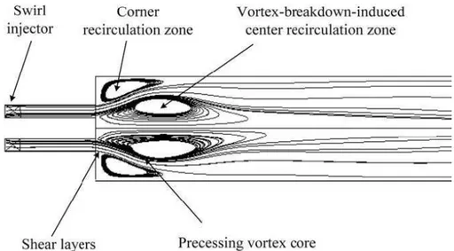
I.7.1.3 Precessing Vortex Core and Central Recirculation Zones in lean premixed swirl injectors 31 I.8 Active combustion control... 34
I.8.1 Combustion instability control... 35
I.8.2 Emission minimizing control ... 36
I.8.3 Burner pattern factor control... 36
I.9 Future ... 37
References ... 38
II. Thermo-acoustic instabilities: fundamental processes and mechanisms...42
II.1 Introduction... 42
II.2 Acoustic-vortex-flame interactions in Gas Turbines ... 43
II.2.1 Characteristics of acoustic, vortical and entropy disturbances ... 44
II.2.2 Length and time scales ... 44
II.3 Combustion instabilities in the new generation of gas turbine ... 47
II.3.1 Decreasing in pollutant emission ... 47
Thermoacoustic instabilities in Gas Turbine burner: new diagnostic methodology
Emanuele Giulietti
PhD thesis, February 2011 “Roma TRE” University
ii emission 50
II.3.3.1 Local phenomena ... 50
II.3.3.2 Overall phenomena ... 50
II.3.3.2.1 Global heat-release rate ... 51
II.3.3.2.2 Overall chemiluminescence emission of flames ... 53
II.3.3.2.3 Flame Describing Function ... 56
II.3.4 Combustion noise... 57
II.3.4.1 Introduction of noise and sound: Sound Pressure Level and frequency ... 57
II.3.4.2 Mechanisms of industrial combustion equipment noise ... 58
II.3.4.3 Acoustic noise emissions in the combustor ... 61
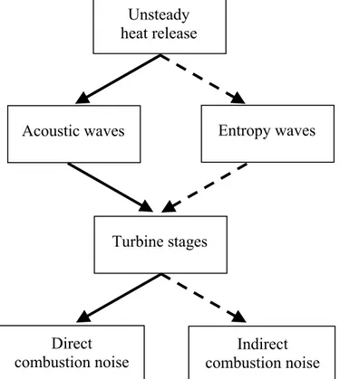
II.3.4.3.1 Noise propagation from the combustion chamber... 61
II.3.4.3.2 Direct combustion noise ... 64
II.3.4.3.3 Indirect combustion noise (entropy noise) ... 66
II.3.5 Experimental diagnostics of combustion instability ... 68
II.3.5.1 Spectral analysis... 68
II.3.5.2 Directivity effects... 69
II.3.5.3 The thermo-acoustic efficiency... 69
II.4 Flame/acoustic interactions ... 70
II.4.1 Coupling mechanisms between acoustic waves and flames ... 71
II.5 Causes of instabilities and damping processes ... 72
II.5.1 Feedback loop responsible for combustion instabilities ... 73
II.5.2 Mechanisms of driving combustion instabilities... 74
II.5.2.1 Energy transfer mechanisms ... 79
II.5.3 Frequency ranges in combustion instabilities ... 81
II.5.4 Acoustic motion in combustor chamber: resonant frequencies ... 83
II.5.5 Damping processes... 88
II.5.6 State of art ... 88
II.6 Critical review of causes and effects of instabilities... 89
II.6.1 Pressure oscillations and radiative emission of flame: early combustion noise theory and comparison with experiments ... 89
II.6.2 Vortex shedding due to hydrodynamic instability ... 91
II.6.3 Change of flame surface area in premixed flames ... 92
II.6.4 Equivalence ratio fluctuation ... 94
II.6.5 Non-premixed flames and pilot flame... 95
II.6.6 Nearfield effects ... 95
II.6.7 Confinement effects on combustion noise ... 95
II.6.8 Hysteresis ... 97
II.6.9 Combustion roar and Strouhal-type combustion noise in real burners ... 97
II.6.10 Nonlinear mechanisms and limit cycle in combustion instabilities ... 99
II.6.11 Acoustic modal analysis of a full-scale annular combustor in propulsion engine102 References ... 104
III. Control strategies: passive and active control ...122
III.1 Passive control ... 122
III.1.1 Methods to improve combustion stability... 122
Thermoacoustic instabilities in Gas Turbine burner: new diagnostic methodology
Emanuele Giulietti
PhD thesis, February 2011 “Roma TRE” University
iii
III.1.2.2 Quarter-wave tubes ... 127
III.2 Active control... 128
III.2.1 Sensors and diagnostic techniques for the monitoring and control of practical flames 130 III.2.1.1 Pressure Measurements... 131
III.2.1.2 Flame Spectroscopy and Chemiluminescence Measurements... 133
III.2.1.3 Acoustical-optical technique in high-pressure case ... 136
III.2.2 Controller ... 136
III.2.3 Actuators ... 137
III.2.4 Advantages of active control... 138
References ... 139
IV. Thermo-acoustic instabilities: analytical and numerical models...145
IV.1 Introduction... 145
IV.2 Hybrid approaches for the investigation of combustion noise... 146
IV.3 Brief critical review of analytical models... 147
IV.3.1 One-dimensional analytical model in industrial gas turbine... 147
IV.3.2 Numerical models of interaction phenomena in combustion noise: amplifiers and resonators ... 148
IV.3.3 Noise prediction method and combustion noise scaling laws... 149
IV.3.3.1 Overall sound pressure level (OASPL)... 150
IV.3.3.2 Acoustic power spectral density (PSD)... 151
IV.4 Lighthill’s aeroacoustic theory and combustion noise theories ... 153
IV.5 Acoustics equation for non-reacting and reacting flows ... 154
IV.5.1 Acoustics for non-reacting flows ... 155
IV.5.2 Acoustics for reacting flows... 157
IV.5.3 A wave equation in low Mach-number reacting flows ... 158
IV.6 The acoustic energy balance in reacting flows ... 159
IV.6.1 Acoustic energy density and flux... 159
IV.6.2 Extended of the acoustic energy equation... 160
IV.7 Criteria for combustion instability... 164
IV.7.1 Classical Rayleigh’s criterion ... 164
IV.7.2 Extended Rayleigh’s criterion... 167
IV.7.3 Classical and extended Chu’s criterion ... 168
IV.7.3.1 Expression for a stabilizing factor by means the instantaneous density of acoustic energy... 168
IV.7.3.2 Derivation of the acoustic energy budget from LES... 169
IV.7.4 Considerations about criteria from energy equations... 173
IV.7.5 Extended analysis for non-zero mean flow... 176
References ... 177
V. An application of instability control to Heavy Duty Gas Turbine: Siemens Vx4.3A ...181
Thermoacoustic instabilities in Gas Turbine burner: new diagnostic methodology
Emanuele Giulietti
PhD thesis, February 2011 “Roma TRE” University
iv
avoiding them... 184
V.1.1.1 Passive control of Vx4.3A ... 185
V.1.1.2 Active control of Vx4.3A... 187
V.1.2 Burner systems for syngas application in Vx4.3A’s annular combustion chamber 189 V.1.2.1 Integrated Gasification Combined Cycle technology and the employment of syngas 189 V.1.2.2 Syngas application in Siemens Vx4.3A ... 190
References ... 192
Part 2: A NEW DIAGNOSTIC METHODOLOGY FOR THERMOACOUSTIC INSTABLITIES DETECTION AND CONTROL...193
VI. Background concepts: conventional optical techniques and theoretical approach for thermal emission of flames ...194
VI.1 Emission spectra of flames ... 194
VI.1.1 Origin of spectra... 195
VI.1.2 Qualitative information on the heat release rate by flame spectral analysis ... 197
VI.2 Conventional optical techniques ... 198
VI.2.1 Optical techniques for concentration of chemical species ... 198
VI.2.2 Optical techniques for velocity measurements ... 202
VI.2.3 Optical techniques for temperatures... 203
VI.2.4 Combined laser techniques for simultaneous measurements... 205
VI.2.4.1 PIV study of acoustic-flame interaction... 206
VI.2.4.2 PLIF study of acoustic-flame interaction and flame front ... 206
VI.2.4.3 Simultaneous PIV and PLIF measurement ... 207
VI.3 Image-based techniques for the monitoring of flames: CCD cameras... 207
VI.4 Recent optical sensors... 208
VI.5 Applicability of infrared emission and absorption spectra to determination of hot gas temperature profiles ... 209
VI.6 Theoretical approach of the radiation absorption/emission process... 211
VI.6.1 Homogeneous system and monochromatic radiation ... 211
VI.6.2 Non-homogeneous system and monochromatic radiation ... 213
VI.6.3 Non-homogeneous system and wide-band radiation ... 214
References ... 216
VII. A novel approach: the ODC technique...221
VII.1 Motivations and objectives ... 221
VII.2 ODC: new diagnostic technique in ENEA ... 222
VII.3 Introduction about total radiation emitted by flames ... 224
VII.4 Optical apparatus and burners... 225
VII.5 Spectral analysis of radiative emission by ODC technique... 226
VII.6 Physical Interpretation of Radiative Emission Scaling ... 229
Thermoacoustic instabilities in Gas Turbine burner: new diagnostic methodology
Emanuele Giulietti
PhD thesis, February 2011 “Roma TRE” University
v
VIII. Results in industrial burners, Discussion and Conclusions ...236
VIII.1 Introduction... 236
VIII.2 Experimental set-up and first ODC applications... 237
VIII.2.1 250kW Premixed Liquid Oil/Air Savona Burner... 239
VIII.2.2 300kW Nonpremixed H2/O2 MICOS Burner ... 242
VIII.2.3 500kW Premixed CH4/Air TG500 Burner ... 243
VIII.3 1MW Premixed CH4/Air COMET-HP Burner ... 246
VIII.3.1 Burner V64.3A... 246
VIII.3.2 Test Rig ... 247
VIII.3.3 Operating conditions ... 250
VIII.3.4 Flame chemiluminescence spectrum of V64.3A burner ... 250
VIII.3.5 Experimental unsteady characterization and results ... 251
VIII.4 Application to Control Systems ... 258
VIII.5 Conclusions ... 259
References ... 259
Thermoacoustic instabilities in Gas Turbine burner: new diagnostic methodology
Emanuele Giulietti
PhD thesis, February 2011 “Roma TRE” University
vi
A. ATTACHMENT A: LIGHTHILL’S THEORY ... 261
A.1 Introduction ... 261
A.2 Lighthill’s equation ... 261
A.3 Consideration about the exact solution of Lighthill’s equation ... 265
A.4 Related model equations and approximation ... 267
A.5 Noise in Jet engine: turbojet and turbofan ... 268
References of attachment A... 270
B. ATTACHMENT B: RANDOM SIGNALS AND SPECTRAL ANALYSIS ... 271
B.1 Probability density function ... 271
B.2 Probability distribution function ... 272
B.3 Calculation of averages... 273
B.3.1 Mean value (first statistic moment)... 273
B.3.2 Mean square value (second statistic moment) ... 273
B.3.3 Central moment: standard deviation, variance, skewness and kurtosis ... 274
B.3.4 Random process and ensemble averaging... 275
B.4 Correlation... 275
B.4.1 Auto-correlation ... 276
B.4.2 Cross-correlation and covariance... 278
B.5 Fourier analysis ... 279
B.5.1 Fourier series... 279
B.5.2 Fourier integral... 280
B.5.3 Complex form of the Fourier transform... 280
B.6 Power Spectral Density (PSD)... 281
B.6.1 Narrow-band and broad-band processes ... 283
B.6.2 Cross-spectral density (CSD)... 285
B.6.3 Coherence function ... 286
References of attachment B... 286
C. ATTACHMENT C: ACOUSTIC SIGNALS ANALYSIS ... 287
C.1 Acoustic auto-correlations and auto-spectra ... 287
C.1.1 The r.m.s. pressure coefficient ... 288
C.2 Acoustic cross-correlations and cross-spectra... 288
C.3 Convection velocity ... 289
C.4 The concept of decibel... 290
C.4.1 Sound Power level... 291
C.4.2 Sound Intensity level... 291
C.5 Sound Pressure Level distribution and OASPL... 292
C.6 Spectra in terms of 1/n-octaves ... 292
C.6.1 Filters and frequency weighting... 295
C.7 Fluctuating pressures and vibration of structures... 295
Thermoacoustic instabilities in Gas Turbine burner: new diagnostic methodology
Emanuele Giulietti
PhD thesis, February 2011 “Roma TRE” University
vii
D.1 Introduction ... 297
D.2 The transport equations ... 297
D.2.1 Transport equation of mass ... 298
D.2.2 Transport equation of momentum... 298
D.2.3 Transport equation of total energy (internal + mechanical)... 300
D.2.4 Transport equation of species mass fraction ... 301
D.2.5 Thermodynamic Equation of State... 302
D.3 Solution of a multicomponent-species system... 303
D.4 Some chemistry definitions... 304
D.5 Some thermodynamics definitions... 304
D.5.1 Enthalpy ... 305
D.5.2 Entropy... 305
D.5.3 Internal Energy... 306
D.5.4 Sound velocity... 306
References of attachment D... 307
E. ATTACHMENT E: LAWS FOR THERMAL RADIATION ... 308
E.1 The importance of emissivity for physical processes ... 308
E.2 Physical laws for thermal radiation... 308
E.2.1 Radiant heat transfer ... 308
E.2.2 Planck radiation law... 309
E.2.3 Stefan-Boltzmann equation... 310
E.2.4 Wien’s displacement equation ... 311
E.2.5 Kirchhoff’s law of radiation... 312
new diagnostic methodology
Emanuele Giulietti
“Roma TRE” University
Thermoacoustic instabilities in Gas Turbine burner: new diagnostic methodology
Emanuele Giulietti
PhD thesis, February 2011 “Roma TRE” University
1
List of symbols
Uppercase Roman A flame surface [m2] A absorbance [−]
Ai generic chemical species [−] D mass diffusivity [m2 s−1] Da Damköhler number, = ch t τ τ [−]
Di effective diffusion coefficient of species i into the gas mixture [m2 s−1] Dij binary mass diffusivity [m2 s−1]
T ij
D thermo-diffusion coefficient [m2 s−1]
E energy per unit volume [J m3] E specific internal energy [J kg−1] E strain rate tensor [s−1]
Ea activation energy of chemical reactions [J kg−1]
E1 period-averaged acoustic energy in the whole combustor [J = kg m+2 s−2] E[x] statistical expectation of x
F force per unit volume [kg m-2 s-2]
F1 period-averaged acoustic flux leaving the combustor (acoustic losses) [W=Js−1= kgm+2s−3]
ℑ Fourier transform;
G specific Gibbs’ free energy [J kg−1]
He helicity, = ω⋅u [m s−2]
H specific enthalpy [J kg−1] I identity matrix [-]
I radiant energy [J]
I spectral irradiance [Wm-3 = J m-3s-1 ]
Ji chemical species diffusive mass flux [kg m−2 s−1] K specific kinetic energy [m2 s−2]
K thermal conductivity coefficient [J m−1 K−1 s−1] Ka Karlovitz number, = st ch τ τ [−] L macroscale length [m] L the path length [m] La acoustic length scale [m] Lei Lewis number, = Pr Sc Di = α [−] M Mach number, = c U [−]
Thermoacoustic instabilities in Gas Turbine burner: new diagnostic methodology
Emanuele Giulietti
PhD thesis, February 2011 “Roma TRE” University
2 Ns number of chemical species
P power [W]
P(x) probability distribution function Pr Prandtl number, = K cp μ [−] loss
Q& heat loss [J m−3 s−1]
R
Q& heat source [J m−3 s−1]
R universal gas constant, = 8.314 [J mol−1K−1]
R1 averaged source term in criteria for combustion instability [W = J s−1= kg m+2 s−3]
R Correlation function;
Rx Auto-correlation function for the stationary random process x(t)
Rxy Cross-correlation function between the stationary random processes x(t) and y(t) Re Reynolds number, = ν μ ρUl = [−] Ul Rg gas constant [J kg−1K−1] S surface [m2]
S Power Spectral Density S Swirl number
Sx Auto-spectral density function of the stationary random process x(t)
Sxy Cross-spectral densities between the two stationary random processes x(t) and y(t) Sci Schmidt number, = D ν [−] St Strouhal Number [−] T temperature [K] T period [s]
Tref reference temperature, 298.15 [K] TIT Turbine Inlet Temperature [K]
U specific internal energy [J kg−1 = N m kg−1 = m+2 s−2] U velocity [m s-1]
V volume [m3]
Vi diffusion velocity of species i [m s−1] Wi molecular weight of species i [kg mol−1] Wmix mixture molecular weight [kg mol−1]
Wx equivalent one-sided spectral density function Xi molar concentration of species i [mol m-3] Xi volumetric fraction of species i [−]
Yi mass fraction of species i [−]
Lowercase Roman
a absorptivity (or absorption coefficient) [−] c local velocity of sound [m s−1]
Thermoacoustic instabilities in Gas Turbine burner: new diagnostic methodology
Emanuele Giulietti
PhD thesis, February 2011 “Roma TRE” University
3
cv specific heat at constant volume [J kg−1K−1] di diffusional driving force [m−1]
e energy per unit mass [J kg−1 = N m kg−1 = m+2 s−2] es specific sensible internal energy per unit mass [J kg−1] et specific total energy per unit mass [J kg−1]
e1 acoustic energy in reacting flow [kg m−1 s−2]
f body force per unit of mass [m s−2] f frequency [Hz]
f1 local acoustic flux [kg s−3]
h Plank constant = 6.626 ·10−34 [ J s ] h fluid specific enthalpy [J kg−1 = m+2 s−2] hs specific sensible enthalpy [J kg−1 = m+2 s−2 ]
0 ,k
f
h chemical formation enthalphy [J kg−1 = m+2 s−2]
i specific chemiluminescence emission [J m-3] j imaginary unit (j = −1)
k a unit vector in the z-direction k wavenumber [m−1]
kB Boltzmann constant = 1.380 ·10−23 [ J·K−1 ]
k thermal conductivity [W m−1 K−1] = [J m−1 K−1 s−1] l generic length scale [m]
m mass [kg]
m mean value of a random variable
p pressure [kg m−1 s−2]
p(x) (first order) probability density function describing the distribution of the random variable x
p(x,y) second-order probability density function describing the joint distribution of the random variable x and y
q heat flux [J m−2 s−1]
qD Dufour heat flux [J m−2 s−1] qF Fourier heat flux [J m−2 s−1] qVi diffusional heat flux [J m−2 s−1] r vector position [m]
r1 source term [kg m−1 s−3]
s specific entropy [J kg−1K−1]
sL laminar flame speed [m s−1] t time [s]
'
rms
u rms velocity fluctuation [m s−1]
u velocity vector [m s−1]
u fluid velocity component in x direction [m s−1] v fluid velocity component in y direction [m s−1] w fluid velocity component in z direction [m s−1] x, y, z frame coordinates
Thermoacoustic instabilities in Gas Turbine burner: new diagnostic methodology
Emanuele Giulietti
PhD thesis, February 2011 “Roma TRE” University
4 Uppercase Greek
Δ difference between two values Φ equivalence ratio [−] Σ surface density [m-1] Lowercase Greek α thermal diffusivity, = p c K ρ [m2s-1] λ α spectral absorptivity [−]
δ boundary layer thickness [m]
δij the Kronecker delta (δij=0 when i≠j; δij=1 when i=j) δF flame front thickness [m]
δr flame front reaction thickness [m]
ε (or ελ) emissivity, or spectral emissivity, or radiant emittance factor in the range 0-1 [−] γ specific heat ratio (=cp/cv) [−]
η Kolmogorov dissipative length scale [m]
ϕ phase angle of the Power Spectral Density [rad] λ wavelength,
f c
= [m]
λ second viscosity coefficient [kg m−1 s−1] λT Taylor length scale [m]
μ first viscosity coefficient or dynamic (molecular) viscosity [kg m−1 s−1] μB bulk viscosity [kg m−1 s−1]
ν kinematic viscosity [m2 s−1]
ρ fluid density [kg m−3]
ρxy Correlation coefficient (normalized Covariance) for the random variables x(t) and y(t)
σ standard deviation
σ Stefan-Boltzmann constant = 5.67 ·10 − 8 [W m−2 K−4]
σ stress tensor [kg m−1 s−2]
τ generic Δτ time separation [s]
τ transmissivity [−]
τ viscous stress tensor [kg m−1 s−2]
τ0 maximum Δτ of the Cross-Correlation function [s] τa acoustic time [s]
τc convective time [s] τt turbulent time [s] τch chemical time [s] ω vorticity [s−1]
Thermoacoustic instabilities in Gas Turbine burner: new diagnostic methodology
Emanuele Giulietti
PhD thesis, February 2011 “Roma TRE” University
5
ω f
T π
π
2
2 = ; pulsation or angular frequency [rad s−1]
k
ω& volumetric rate of production [kg m−3 s−1]
T
ω& heat release due to combustion per unit volume [W m−3 = J m−3 s−1 = kg m−1 s−3]
i
ω& reaction rate (production/destruction rate) of species i [kg m−3 s−1]
R
ω& reaction rate [mol m−3 s−1]
Subscripts
a acoustic
b burnt (gases)
c convection
f flame, reacting region g mixture gas
p hot products R cold reactants r chemical reaction rad radicals
ref reference quantities rms root mean square
s chemical species
S surrounding space
t total
u universal
u unburnt (gases)
∞ quantities in unperturbed flow
0 reference quantities Superscripts * dimensionless quantity 0 formation quantity ′ fluctuation quantity Acronyms
ACC Active Combustion Control
AE Acoustic Energy
AEE Acoustic Energy Equation
APE-RF Acoustic perturbation equations for reacting flows CAA Computational Aero-Acoustics
Thermoacoustic instabilities in Gas Turbine burner: new diagnostic methodology
Emanuele Giulietti
PhD thesis, February 2011 “Roma TRE” University
6 CARS Coherent Anti-Stokes Raman Scattering CCA Computational Combustion Acoustics
CRZ Central Recirculation Zone formed by swirling flow DCM Direct Computational Methods
DFWM Degenerate Four Wave Mixing DLE Dry Low Emissions
DLN Dry Low NOx (i.e., lean-premixed combustion technologies) DNS Direct Numerical Simulation
DOE U.S. Department of Energy e.g. exempli gratia
EC European Commission
ENEA Italian National Agency for New Technologies, Energy and Sustainable Economic Development
EU European Union
EVI-GTI European Virtual Institute – Gas Turbine Instrumentation FBG Fiber Bragg Gratings
FDF Flame Describing Function FE Fluctuation Energy
FEE Fluctuation Energy Equation FFT Fast Fourier Transform FPI Fabry-Perot Interferometer HCRV helical central recirculation vortex, HFD High-frequency dynamics
HiTAC High Temperature Air Combustion HOV helical outer vortex,
HP High Pressure
ICCD Intensified Charge-Coupled Device camera IEA International Energy Agency
i.e. id est
IGCC Integrated Gasification Combined Cycle IP Intermediate Pressure
IR infrared light (750 –1000000 nm = 0.75 – 1000 μm) l.h.s. left-hand side
LBO lean blow-off
LFD Low-frequency dynamics LDV Laser Doppler Velocimetry LES Large Eddy Simulation LIF Laser Induced Fluorescence LII Laser Induced Incandescence LMS Least-Mean-Square Algorithm MFD Mid-frequency dynamics
NIR near infrared light (750 –1400 nm)
OASPL OverAll Sound Pressure Level, total radiated sound power OEM Original Equipment Manufactures
PDA Phase Doppler anemometry PIV Particle Image Velocimetry
Thermoacoustic instabilities in Gas Turbine burner: new diagnostic methodology
Emanuele Giulietti
PhD thesis, February 2011 “Roma TRE” University
7
PIWG Propulsion Instrumentation Working Group Consortium PLIF Planar Laser Induced Fluorescence
PRI pseudo-Rayleigh index PTV Particle Tracking Velocimetry PVC precessing vortex core
r.h.s. right-hand side r.m.s. root mean square
RANS Reynolds Averaged Navier-Stokes SOI Silicon-On-Insulator
SPL Sound Pressure Level
SRS (or SpRS) Spontaneous Raman Scattering
Syngas Synthesis gas: a variable mixture of primarily hydrogen and carbon monoxide. TBL Turbulent Boundary Layer
TDLAS Tunable Diode Laser Absorption Spectroscopy UHC unburned hydrocarbon fuel
UV ultraviolet light (190 – 370 nm) VIS visible light (370 – 750 nm)
Thermoacoustic instabilities in Gas Turbine burner: new diagnostic methodology
Emanuele Giulietti
PhD thesis, February 2011 “Roma TRE” University
Thermoacoustic instabilities in Gas Turbine burner: new diagnostic methodology
Emanuele Giulietti
PhD thesis, February 2011 “Roma TRE” University
9
Abstract
Gas turbine engines for power generation and propulsion applications have traditionally used diffusion-flame combustors because of their reliable performance and reasonable stability characteristics. Unfortunately, this type of combustor usually produces unacceptably high levels of thermal NOx. The increasingly strict regulation for pollutant emissions has recently led engine manufacturers to develop combustors that meet various regulatory requirements. New concepts for combustion technology have been introduced to the Gas Turbine industry, including lean-premixed combustion.
Lean-premixed combustion appears to be the most promising technology for practical systems at the present time. In lean-premixed combustion, the fuel and air are premixed upstream of the combustor to avoid the formation of stoichiometric regions. The combustion zone is operated with excess air to reduce the flame temperature; consequently, thermal NOx is virtually eliminated.
Unsteady flow oscillations, also referred to as combustion instability, however, have emerged as a common problem, and hindered the development of lean-premixed combustors. These oscillations may reach sufficient amplitudes to interfere with engine operation, and in extreme cases, lead to failure of the system due to excessive structural vibration and heat transfer to the chamber. The associated pressure oscillations and possibly enhanced heat transfer can lead to a deterioration in the system performance, and may be sufficiently intense to cause structural damage.
Combustion instability remains a critical issue limiting the development of low-emission, lean-premixed Gas Turbine combustion systems.
Combustion oscillations are not limited to gas turbine engines. They have been observed in the development of virtually all propulsion systems, including liquid rocket engines.
The system usually operates near the lean blowout limit, then a small perturbation in the equivalence ratio may produce a significant variation in heat release, which, if it resonates with the chamber acoustic wave, can result in large excursions of combustion oscillations. The phenomenon may be defined as the unsteady motions in a dynamic system capable of sustaining large oscillations over a broad range of frequencies.
The work is organized in two parts: an extensive bibliographic review of combustion instabilities and the motivation of this work in part 1; and the study about a new diagnostic methodology for thermoacoustic instabilities detection and future control in part 2. The part 1 is important because of lack of books that describe clearly and exhaustively the complex phenomenology of thermoacoustic instabilities, however the experts of thermoacoustic instabilities can skip directly from it to part 2 where is possible to find the improvements with respect to the state of the art. The part 1 is organized into five chapters. The chapter 1 gives a general background about modern Gas Turbine engine and shows the need of new sensors for measurements systems. The chapter 2 explains the characteristic of combustion noise, investigates the mechanisms driving combustion instabilities, the causes of instabilities and damping processes, and then provides a comprehensive review of the advances made in thermo-acoustic instabilities. The physics of combustion oscillations, most commonly caused by a coupling between acoustic waves and
unsteady heat release, are discussed, and the concept of using feedback control to interrupt these
Thermoacoustic instabilities in Gas Turbine burner: new diagnostic methodology
Emanuele Giulietti
PhD thesis, February 2011 “Roma TRE” University
10
active control of combustion instabilities. The objective is to optimize combustor operations, monitor the process and alleviate instabilities and their severe consequences. It contains a review of some facets of combustion and focuses on the sensors that take or could take part to combustion control solutions. The chapter 4 provides a critical review of analytical and numerical models and criteria for combustion instability. The chapter 5 shows an application of instability control to real heavy duty Gas Turbine of Vx4.3A Siemens-Ansaldo. It shows the final purpose of the studies about thermo-acoustic instability and one of the industrial fields where the new technique ODC proposed here could be easily applied.
The part 2 is organized into three chapters. The chapter 6 explains the conventional optical techniques for concentration of chemical species, velocity measurements and temperatures, and then it gives a theoretical approach for thermal emission of flames. The chapter 7 proposes a new diagnostic technique named ODC (Optical Diagnostics of Combustion) developed and patented in ENEA and it shows an experimental approach for radiative emission of flames. Radiant energy spectra have the same dynamics of Turbulence (macroscale, inertial and dissipative ranges; slope= -5/3) and reveal Chemical Kinetics high frequency effects. The chapter also explains why Radiant Energy shows Turbulence dynamics. The chapter 8 shows the results and gives an experimental proof that real-time information of combustion instabilities and mean velocity component can be performed by analyzing Radiant Energy captured by means of photo-diodes (ODC). It investigates the use of flame Radiant Energy signal: due to its relation with both Turbulence and Chemical Kinetics, it may reveal the state of a flame and the eventual instability precursor events. It shows experimental analysis of turbulent premixed combustion by means of ODC to laboratory and industrial burners. A collection of radiative emissions by several flames is analyzed in this chapter. Such flames have been obtained in a number of burners in a large range thermal power (i.e., 3 kWt-1MWt), either premixed or not, fed with different fuels (i.e., methane, hydrogen, oil) and with different physical states (i.e., gas and liquid fuel), while radiative emission is collected by means of a photo-diode. The purpose of this chapter is to show that the usefulness of measurements of Radiant Energy emission from flames can be enhanced by focusing on a spatially limited region, by means of the auto-correlation and cross-correlation of signals from two points.
Finally it shows the fulfilment of a test facility for real burner in ENEA Research Center, i.e.,
COMET-HP (COMbustion Experimental Tests in High Pressure), 1 MWt premixed CH4/Air and gives several experimental tests.
Concluding, a new optical instrument based on photo-diodes, called ODC, has been applied for thermoacoustic instability analysis. ODC provides information at very low cost and in real time about turbulent and chemical scales.
Lastly five attachments conclude the PhD thesis. The attachment A shows Lighthill’s theory and acoustic analogy whereby the governing equations of motion of the fluid are coerced into a form reminiscent of the wave equation of “classical” (i.e. linear) acoustics. The attachment B provides a brief explanation of random signals, e.g. random vibrations, and spectra analysis, according to which a periodic function can be broken down into its harmonic components. The attachment C presents an analytical treatment of acoustic signals. The attachment D gives a theoretical approach for thermodynamic equations. Turbulent combustion is a multi-scale problem where complexity lies in the interaction between fluid dynamics and chemistry. This attachment provides a theoretical understanding of some of the scale physics in turbulent reacting flows. The
Thermoacoustic instabilities in Gas Turbine burner: new diagnostic methodology
Emanuele Giulietti
PhD thesis, February 2011 “Roma TRE” University
11
attachment E provides laws for thermal radiation. At high temperatures thermal radiation is the main mode of heat transfer.
Thermoacoustic instabilities in Gas Turbine burner: new diagnostic methodology
Emanuele Giulietti
PhD thesis, February 2011 “Roma TRE” University
Thermoacoustic instabilities in Gas Turbine burner: new diagnostic methodology
Emanuele Giulietti
PhD thesis, February 2011 “Roma TRE” University
13
I. Background about modern gas turbine engine
Thermoacoustic instabilities in Gas Turbine burner: new diagnostic methodology
Emanuele Giulietti
PhD thesis, February 2011 “Roma TRE” University
14
I. Background about modern gas turbine engine
I.1 Introduction
Combustion systems are among the most challenging technologies to study. There are not only high temperatures, but usually very high temperature gradients ranging from the incoming reactants at ambient temperature up to flame temperatures. The fluid flow is typically turbulent and may include swirl. The heat transfer includes conduction, convection and radiation. The radiation is further complicated by the spectral nature of gaseous combustion products. The chemistry is extremely complicated, where the combustion of a relatively simple fuel like methane can involve hundreds of chemical reactions and dozens of species.
The fuel composition can vary widely and may contain multiple components, waste products, and sometimes multiple phases, depending on the process. The length scales in industrial combustion process may vary by orders of magnitude, ranging from millimetres for fuel injection ports up to meters for the combustor itself.
The materials being heated may be solids, liquids or gases and have a wide range of properties. The field of industrial combustion is very broad and touches, directly or indirectly, nearly all aspects of our lives. The electronic devices we use are generally powered by fossil fuel fired power plants. The cars we drive use internal combustion engines. The planes we fly in use jet fuel powered turbine engines.
As the science of combustion combines heat transfer, thermodynamics, chemical kinetics and multiphase turbulent fluid flow to name a few areas of physics, the study of industrial combustion is interdisciplinary by necessity.
Most of the energy (86%) is produced by the combustion of fossil like petroleum, natural gas and coal. According to U.S. Department of Energy (DOE), the demand in the industrial sector is projected to increase by 0.8% per year to the year 2020 [ I-1].
Pollution regulations vary by location and continue to get more rigorous. Technology continues to improve as the emission requirements get more stringent.
The U.S. Department of Energy sponsored a workshop to develop a roadmap for industrial combustion technology. The resulting report ([ I-2], [ I-3]) identified the following priority research and development needs:
• Determine advanced methods to maintain a stable flame and achieve low emissions while using different fuels.
• Develop a burner capable of adjusting operating parameters in real time.
• Develop real-time sensors and process controls that are more reliable and robust in harsh environments.
• Develop computational tools that are more accurate in a wide variety of applications through the collection of physical data and model validation.
• Create a pathway to demonstrate and commercialize new technologies and enable information sharing throughout industry about new technologies.
• Develop robust design tools that are more user-friendly and accurate, especially with complex phenomena such as turbulence and create a unified code to allow sharing of information more easily and speed development.
I. Background about modern gas turbine engine
Thermoacoustic instabilities in Gas Turbine burner: new diagnostic methodology
Emanuele Giulietti
PhD thesis, February 2011 “Roma TRE” University
15
A key aim within Europe and the rest of the world is the cost-effective production and use of energy with reduced emissions at local and global levels. This will be achieved in part by increasing the efficiency of fossil fuel based energy conversion processes, and in part by increasing the utilisation of new and renewable energy sources in the energy system.
The European Commission (EC) has set targets for the development of gas turbines, to achieve in the long term >65% combined cycle efficiencies and >35% simple cycle efficiencies for small scale gas turbines.
To achieve these higher cycle efficiencies, gas turbines are required to operate at higher firing temperatures and higher operating pressures. Firing temperature has an impact on the emission of thermal-NOx, where NOx production becomes significant at flame temperatures above around 1800 K. In order to achieve low NOx emissions, below 25 ppmv (15% O2, dry), without the use of diluent injection, two elements are required:
Firstly, a near homogenous air/fuel mixture should be provided prior to combustion (premixing), to ensure locally uniform and low reaction temperatures.
Secondly, the reaction zone should be operated well away from stoichiometric conditions i.e. fuel lean.Due to its simplicity, efficiency and reliability, the lean premix combustion approach, known also as Dry Low Emissions (DLE), has become the industry standard for achieving the emission targets of modern gas turbines.
However, the lean-premix combustion technique is susceptible to combustion induced
thermoacoustic pressure pulsations, or oscillations, due the reduced local reaction temperatures.
In the last thirty years noise emission has developed into a topic of increasing importance to society and economy. In fields such as air, road and rail traffic, the control of noise emissions and development of associated noise-reduction technologies is a central requirement for social acceptance and economical competitiveness. The noise emission of combustion systems is a major part of the task of noise reduction. The following aspects motivate research [ I-4]:
•
Modern combustion chambers in technical combustion systems with low pollution exhausts are 5-8 dB louder compared to their predecessors. In the operational state the noise pressure levels achieved can even be 10-15 dB louder.•
The combustion emissions become a more and more important topic for modern gas turbine engines and for airplanes. The combustion instability and noise issues are one major obstacle for the introduction of green technologies as lean fuel combustion and premixed burners in aero-engines. The direct and indirect contribution of combustion noise to the overall core noise is still under discussion. However, it is clear that the core noise besides the fan tone will become an important noise source in future aero-engine designs.•
The development of layout tools for “quiet” technologies requires calculation methods for predicting of sound power in new technical products.I. Background about modern gas turbine engine
Thermoacoustic instabilities in Gas Turbine burner: new diagnostic methodology
Emanuele Giulietti
PhD thesis, February 2011 “Roma TRE” University
16
I.2 General background about world electricity generation by fuels
World’s ever increasing energy demand poses great challenges to power generation in the future. In reference scenarios of the International Energy Agency (IEA) [ I-5] and the U.S. Department of
Energy (DOE) [ I-1], the electricity generation is projected to double in the next 25 years.
Although the portion of renewables has to increase dramatically, at least in a mid-term perspective, i.e., until 2050, be covered by fossil fuels ([ I-6], [ I-7])
In the IEA and DOE reference scenarios, gas turbines, especially in combined cycle power plants, are one of the key technologies with a projected share of 25% of the total power generation in 2030, as shown in Fig. I-1. Coal-fired power plants are expected to deliver 45%. Other studies see gas turbine power plants even at 30-40% in 2030 [ I-8].
Fig. I-1: Energy mix of world electricity generation by fuels (reproduced from data in reference [ I-1] and [ I-7]). Both the IEA and the DOE scenarios are based on the assumption of a continuation of present policies. It is, however, to be expected that emission restrictions will get even more stringent in the future. Gas turbines feature emission characteristics that are by far better than those of coal-fired power plants. This includes CO2, NOx, and SO2. Compared to coal-fired plants, gas turbines in combined cycle operation achieve a CO2 reduction of approximately 50%. This is due to the lower carbon content in natural gas and a higher efficiency, which for combined cycle plants reaches a value of nearly 60% compared to 45% for coal-fired power plants. Therefore, either the
I. Background about modern gas turbine engine
Thermoacoustic instabilities in Gas Turbine burner: new diagnostic methodology
Emanuele Giulietti
PhD thesis, February 2011 “Roma TRE” University
17
percentage of gas turbines in the energy mix might increase, or parts of the coal-share might be replaced by renewables and the gas turbine portion will be at 25% [ I-7].
The German Federal Ministry of Economics and Technology [ I-8] stated that today gas turbines in single and combined cycle power plants account for more than 50% of the power of new installed plants worldwide.
Besides better emission characteristics and a higher efficiency, gas turbine power plants exhibit several other advantages. These are lower specific investment costs compared to other technologies, flexibility in terms of peak-, part-, and base-load operation, as well as fast installation and amortization times and a smaller footprint [ I-7].
Also, the increase of installed power generated by wind power plants, a fast growing industry, is up to now accompanied by an increase of the installed power of fossil power plants, i.e., mainly gas turbines. This is necessary in order to be able to compensate the power outage in case of an unsteadiness of the wind.
The remarks made in this section underline the importance of gas turbines in the energy mix and thus the importance of getting the problem of thermoacoustic instabilities, which are one of the main issues for gas turbine manufacturers, under control.
I.3 Thermodynamic cycle of modern gas turbine engine
Combustor chambers and turbine first stages are well-known as “black” zones because of the lack of good data due to sensor difficulty to survive and maintaining traceable calibration. Accurate temperature measurements in the first stages of the HP (High Pressure) and IP (Intermediate Pressure) turbine are critical for cooling system design and combustor performance assessment, uncertainty of ± 10 K affects the specific fuel consumption of 0.2%. Temperature and pressure ranges at the combustor exit/HP first stator can be as high as 45 bar pressure for propulsion gas turbines, with temperature higher than 2300 K; at the same location for energy generation gas turbines pressure of 20 bar and temperature up to 2000 K are typical.
Then engine performance assessment requires accurate measurements of total pressure, total temperature and gas composition. The hostile environment where the probe is immersed reduces the life of the sensor and induces quick modification of the properties of the materials, therefore changing the calibration and decreasing the accuracy.
In term of gas path measurements for steady stagnation pressure and temperature a good target for the developers is achieving 0.4% of the reading for temperature measurements and maintaining a 0.05% FS (full scale) for pressure, where the range of applications will be increased to working temperature above 1500 K assuring reliability, constant calibration and long sensor life (ultimate aim is over 20000 hours).
The Turbine Inlet Temperature (TIT) is a critical parameter of Gas Turbine systems influencing both material and coating lifetime of turbines as well as their efficiency. It is well-known that turbine entry temperatures have been steadily increasing over the years in order to increase the thermodynamic cycle efficiency. Over the last 3 decades or so, the turbine entry temperatures have increased by approximately 400°C. Clearly this has put increasing demands on all the materials used for hot section components, including the sensor and sensor packing materials. It should be noted that is not clear whether this trend will continue due to restrictions imposed by EU (European Union) regulations on the formation of oxides of nitrogen (NOx). Hence the
I. Background about modern gas turbine engine
Thermoacoustic instabilities in Gas Turbine burner: new diagnostic methodology
Emanuele Giulietti
PhD thesis, February 2011 “Roma TRE” University
18
turbine entry temperatures can not continue to be increased indefinitely without contravening the goals set by the EU.
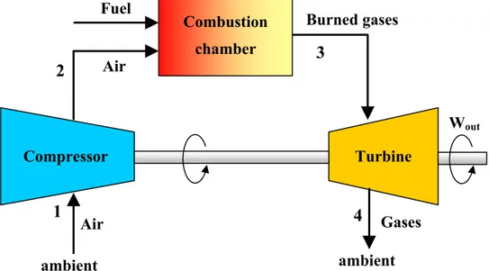
Fig. I-2: Ideal open end Brayton Cycle diagram
Fig. I-3: Brayton cycle (T/s and P/V diagrams)
Temperatures within the gas turbine engine involve an operating range from ambient at inlet to the fan (compressor, 1), with the maximum at the combustor exit (3) where gas temperature can exceed 2000 °C (see Fig. I-3). Thus the challenge to the sensor developer is the most extreme for components and flow from the compressor discharge (2) and through the high pressure turbine (3). P V S=const S=const 1 2 3 4 S T P=const P=const 1 2 3 4 Combustion chamber Turbine Compressor Air ambient ambient Air Fuel Burned gases 1 2 3 4 Wout Gases
I. Background about modern gas turbine engine
Thermoacoustic instabilities in Gas Turbine burner: new diagnostic methodology
Emanuele Giulietti
PhD thesis, February 2011 “Roma TRE” University
19
I.3.1 Fuel and oxidizer: mixing type in combustion burners
Depending upon many factors, certain types of fuels may be preferred for certain geographic locations due to cost and availability considerations. Gaseous fuels, particularly natural gas, are common used in most industrial heating applications in Europe and United States. In Asia and South America, heavy fuel oils are generally preferred although the use of gaseous fuels is on the rise. Fuels also vary depending on the application.
The fuel choice has an important influence on the heat transfer from a flame. In general, solid fuels like coal and liquid fuels like oil produce very luminous flames that contain soot particles that radiate like blackbodies to the heat load. Gaseous fuels like natural gas often produce nonluminous flames because they burn so cleanly and completely without producing soot particles. A fuel like hydrogen is completely nonluminous as there is no carbon available to produce soot.
The predominant oxidizer used in most industrial heating processes is atmospheric air. This can present challenges in some applications where highly accurate control is required due to the daily variations in the barometric pressure and humidity of ambient air. The combustion air is sometimes preheated and sometimes blended with some of the products of combustion, which is usually referred to as flue gas recirculation. For the case of air preheat the adiabatic flame temperature will be increased and result in a subsequent increase of the cycle thermal efficiency. Combustion with High Temperature Air Combustion (HiTAC) has been shown to provide potential for many engineering realities for the twenty-first century.
One common method for classifying burners is according to how the fuel and the oxidizer are mixed:
• In premixed burners the fuel and the oxidizer are completely mixed before combustion begins, than the oxidizer is mixed with the fuel before it reaches the flame front. This creates a thin flame front as all of the reactants are readily available. Premixed burners often produce shorter and more intense flames, compared to diffusion flames.
• A diffusion flame is a flame in which the oxidizer combines with the fuel by diffusion. As a result, the flame speed is limited by the rate of diffusion. Diffusion flames tend to burn slower and to produce more soot than premixed flames because there may not be sufficient oxidizer for the reaction to go to completion, although there are some exceptions to the rule. The soot typically produced in a diffusion flame becomes incandescent from the heat of the flame and lends the flame its readily identifiable orange-yellow colour. Diffusion flames tend to have a less-localized flame front than premixed flames.
I.4 Theory and experimental observations
It is extremely important to pay attention to the experience gained in the laboratory as well as in full-scale tests of devices. Theory is an indispensable aid to making sense of observational results. Conversely, discussion of various experimental observations is a natural place to introduce many of the basic ideas contained in the theory. For practical purposes, the theory often serves most successfully when used to analyze, understand, and predict trends of behaviour, thereby also
I. Background about modern gas turbine engine
Thermoacoustic instabilities in Gas Turbine burner: new diagnostic methodology
Emanuele Giulietti
PhD thesis, February 2011 “Roma TRE” University
20
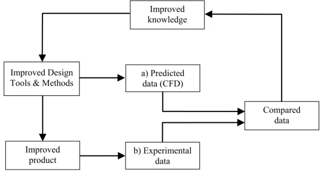
providing the basis for desirable changes in design. Experimental data are always required to produce quantitative results and their accuracy in turn is limited by uncertainties in the data. Fluid flow can be studied in a number of ways: complete experimentation, fully theoretical studies (via modelling) or computational fluid dynamics (CFD) which studies the fluid flow, and predicts heat transfer, mass transfer, chemical reactions, and related phenomena by solving governing mathematical equations using a numerical process. There is a key link between measurements provided by sensors and the result of CFD analyses. Engineering data is used for conceptual studies of new designs (Fig. I-4) and in detailed gas turbine engine development. CFD is relatively low in cost, as using only physical experimental testing to get all essential engineering data for design can be expensive. The CFD simulations are relatively inexpensive, and costs decrease as tools become more powerful. CFD allows the analyst to examine a large number of locations in the region of interest, and yields a comprehensive set of flow parameters for examination.
Fig. I-4: Experimental test and design cycle
In terms of a better understanding of turbulent combustion and in terms of providing experimental data for validation of numerical simulations it is crucial, in general, to vary parametrically Reynolds number, equivalence ratio, fuel composition, pressure and swirl intensity.
I.4.1 Testing
There are numerous reasons why tests are conducted in industrial combustion process:
1. Initial new product development is sometimes done at a reduced scale to minimize costs and
risks. When the product is close to commercialization, large-scale (preferably full-scale) tests
are required to validate the technology. End users are not likely to use a new technology until Improved Design
Tools & Methods
Improved knowledge a) Predicted data (CFD) Compared data b) Experimental data Improved product
I. Background about modern gas turbine engine
Thermoacoustic instabilities in Gas Turbine burner: new diagnostic methodology
Emanuele Giulietti
PhD thesis, February 2011 “Roma TRE” University
21
it has been validated at or near full scale, although they may be willing to do validation testing if the risk is low enough and the reward is large enough.
Testing can be done to determine equipment performance. Performance is a broad term that can encompass many different elements. For burners, some important measurements may include pollution emission (e.g., NOx, CO), turndown range (minimum and maximum firing rates), fuel variability (e.g., hydrogen content), noise, flame shape (length and cross section), heat flux profile, waste destruction capability for waste fuels, and flame stability (a subjective parameter).
2. Testing may be done to generate data that can be used to validate computer models. Nearly all models involve some level of simplification because it is normally prohibitive in terms of time and cost to model the exact physics and because the exact physics are not always known. Experimental validation must be done to show how well models match actual measurements. However, this means the variability in the experimental measurements must be accurately quantified, so the comparisons with modelling results can be fairly judged.
3. Testing is sometimes used to develop empirical models that can be used to predict equipment performance. Then, the performance for any size can be extrapolated from the empirical data, without the need to test every possible size.
4. Testing can be used to validate new experimental techniques. For example, the optical techniques have been tested against more traditional and well-established techniques such as wire thermocouples and pyrometers.
There are relatively few industrial-scale combustion test facilities outside of equipment manufacturers. A report prepared from a workshop sponsored by the U.S. Department of Energy stases: “For the most part, the size and type of laboratory test equipment available are
inadequate, and the costs are prohibitive” ([ I-2] § p.11)
I.5 Need of new sensor for measurement systems
Applications for gas turbine engines have proliferated after World War II and have been key technology contributors to the expansion of modern aero propulsion in commercial flight, operation of ocean and sea vessels, military aircraft, as well as industrial gas turbine power generation. Over time technical challenges have emerged with higher and expanded expectations for improved performance and still better cycle efficiencies. Improvement in engine efficiency has recently acquired even greater focus because of dwindling fossil fuels and increased global warming.
The need to reduce the consumption of hydrocarbon fossil fuel energies and greenhouse gas emissions are worldwide imperatives that drive the gas turbine industry to continue to improve performance. Greater thermodynamic cycle efficiency cannot occur without engines operating at higher temperatures.
Higher cycle temperatures and pressure brings new challenges to the instrumentation community for better measurement methods and development of new approaches and innovation in test technology.
Today new sensors and measurement techniques are needed to provide for high temperature hot section analyses and characterization and that data used to improved CFD and engine modelling tools.
I. Background about modern gas turbine engine
Thermoacoustic instabilities in Gas Turbine burner: new diagnostic methodology
Emanuele Giulietti
PhD thesis, February 2011 “Roma TRE” University
22
The design, development, and fabrication of new sensors and measurement systems for product characterization to support field service problem evaluations as well as new component and centreline engine qualification and certification are an ongoing focus area.
New sensor and measurement technology can provide one of the greatest opportunities to optimize the engine component efficiencies and allow higher operating temperatures. Simplicity in application and durability in operation are two important goals for any new sensor or measurement system.
I.5.1 Sensor development requirements
Research activity, aimed at improving the capability of measuring devices in gas turbine, has been recently funded by the European community through a project called HEATTOP (Accurate High Temperature Engine Aero-Thermal Measurements for Gas Turbine Life Optimisation, Performance and Condition Monitoring). It was a 9 million euro project within the framework 6 (FP6) program, in the aeronautic and space section. The project has started on 1 August 2006, it lasted for three years and it is due to complete in April 2010. It was a collaborative research project, which aims to develop new, more durable, more accurate instrumentation for high temperature gas turbine applications. This project targets the development and improvement of instrumentation to measure pressure, temperature (gas temperature, surface temperature, blade temperature), flow and tip clearance in gas turbines.
Accurate hot gas path measurements (including combustion diagnostics) are recognized as a major need for the assessment of engine component health and performance. Cost of data acquisition and test affordability are probably the biggest concerns for all gas turbine engine programs and OEM (Original Equipment Manufactures) management across the industry landscape.
These facts have been highlighted in a recent study, “The Lab Gap Matrix”, carried by European
Virtual Institute – Gas Turbine Instrumentation (EVI-GTI) [ I-9].
The sensor and measurement requirements have been defined by both the European Union
European Virtual Institute – Gas Turbine Instrumentation (EVI-GTI) organization and the United
States Propulsion Instrumentation Working Group Consortium (PIWG) [ I-10]. A more concerted and cohesive effort is being made to better communicate the needs of the entire EU and US communities to small business suppliers and developers to more effectively address these topics of interest especially high temperature requirements.
The so called “Lab Gap Matrix” has been set-up following the inputs of engine OEM’s (Original
Equipment Manufactures), research groups, small business developers and instrumentation
vendors to indentify the gaps in the instrumentation capability for measuring in gas turbines and aero-engines.
Besides the interest to validate numerical predictions of engine performance, efficiency, and component life, the availability of high temperature steady and unsteady pressure and temperature data would also enable much progress in the field of condition monitoring and active control technologies. The gas turbine environment is a very challenging place for instrumentation given the extremes of pressure and temperature and the wide operating range required.
Combustion chamber or high pressure turbine sections of gas turbines are probably amongst the most hostile environments to perform measurements. Regarding flow conditions at those
I. Background about modern gas turbine engine
Thermoacoustic instabilities in Gas Turbine burner: new diagnostic methodology
Emanuele Giulietti
PhD thesis, February 2011 “Roma TRE” University
23
locations, the highest pressure and temperature of the latest aero-engine thermodynamic cycles exceeds 50 bar and 2000 K, even up to 2200 K peak temperature.
Due to limitations of current experimental techniques and of the severe flow conditions, the measurement of pressure and temperature in the hot sections of modern gas turbines still remains a true challenge for test engineers.
I.5.1.1 High temperature pressure sensors for gas turbine applications
Over the last three decades there has been a requirement to measure time-varying pressures in turbomachinery applications which have necessitated measurement bandwidths in the order of 100 kHz.
The requirement to locate pressure transducers in increasingly hostile environments that has led to the development of high temperature pressure transducers. Future developments aimed at increasing the maximum operating temperature of pressure sensors.
High temperature pressure transducers are primarily used in research or development engines and component rig testing for several purposes:
•
to validate the design methods and develop the engine/component,•
to gain an understanding of the product performance and behaviour,•
to demonstrate that the product complies with the certification and regulatory requirements.High temperature pressure transducers are also routinely used in-service for the measurement of combustion instabilities in industrial gas turbine where the use of very lean fuel/air mixtures, which are required to achieve economical operation, can be accompanied by combustion instabilities which must be minimized to avoid structural damage. In the future, high temperature dynamic pressure transducers are likely to be used in production aero gas turbine.
High performance pressure transducers have been around since 1960’s. The latest evolution of high temperature leadless transducers, utilizing Silicon-On-Insulator (SOI) technology, enabled transducer operability in many harsh environments.
Despite the capability of the latest SOI based technology piezoresistive pressure transducers to withstand temperatures up to 600°C, there are regions of a gas turbine where dynamic gas path pressure are required to be measured which are significantly hotter. A modern high pressure compressor outlet temperature typically exceeds 750°C and the gas temperature in the high pressure turbine can exceed 1400°C. In these ultra high temperature environments the preferred way of measuring these small dynamic pressure reliably is to use either a flush-diaphragm transducer mounted in a water or air cooled jacket, which requires the supply of cool water or air and, although very effective, may be impractical, or the use of a non-resonant Semi-Infinite Tube (SIT) system which removes the pressure transducer from the very hot environment by a distance of up to 1 metre [ I-11].
Manufacturers are currently researching a range of different materials and glasses in order to extend the maximum operating temperature of the leadless packaging and cables from 700°C to at least 900°C in order to realise the full potential of the silicon carbide based pressure transducer technology.
Measurement of the dynamic pressure within the combustor of a gas turbine engine requires a probe which can provide reliable data at high temperatures. Its calibration must be thermally
I. Background about modern gas turbine engine
Thermoacoustic instabilities in Gas Turbine burner: new diagnostic methodology
Emanuele Giulietti
PhD thesis, February 2011 “Roma TRE” University
24
stable, or at least must be easily correctable for temperature variations, and it must have a small temperature sensitivity. They are expensive and often difficult to use. The chief problem is that the mechanical and electrical properties of most common transducer materials change rapidly with temperature as combustion temperatures are approached. Special materials must be used just to ensure the mechanical and electrical survivability of the transducer. The extremely limited availability of high-temperature dynamic pressure calibration sources added to the high initial cost and the necessity for post-processing of data make the routine use of this type of transducer unattractive.
I.5.2 Materials for high temperature and gas turbine operation life
In general operating service above 540 °C is defined as high temperature for gas turbine engines. More specifically, materials which operate at such temperatures consist principally of various stainless, nickel based super alloys, cobalt based alloys, refractory metals, precious metals, monolithic ceramics, metal matrix composites, and ceramic matrix composites. The applications of these high-temperature materials are found in combustors, turbines, and exhaust systems in aircraft propulsion engines and industrial gas turbine.
In order to perform successfully at high temperatures, a material must have at least two essential characteristics:
1. it must be of high strength at temperature, since increasing temperature tends to reduce integrity,
2. it must have resistance to its environment, since time dependent creep, chemical activity, oxidation, and corrosion increase significantly with temperature.
New turbine component materials necessitate new sensors and measurement systems that can also operate at very high temperatures.
Sensor and measurement systems must be robust, reliable, and the expectation is that the sensors can be reused and reapplied to other following test articles. Ultimately the hope is that the sensors would have infinite life and durability.
The durability of a sensor or measurement device may be directly tied to performance or more importantly identify issues regarding equipment safety. Land power generation turbines can operate 24 hours a day and in one year complete 8760 hours of operation. Every hour of downtime for any gas turbine engine whether power generation or aero propulsion is an hour of lost revenue as well as the cost of maintenance and overhaul.
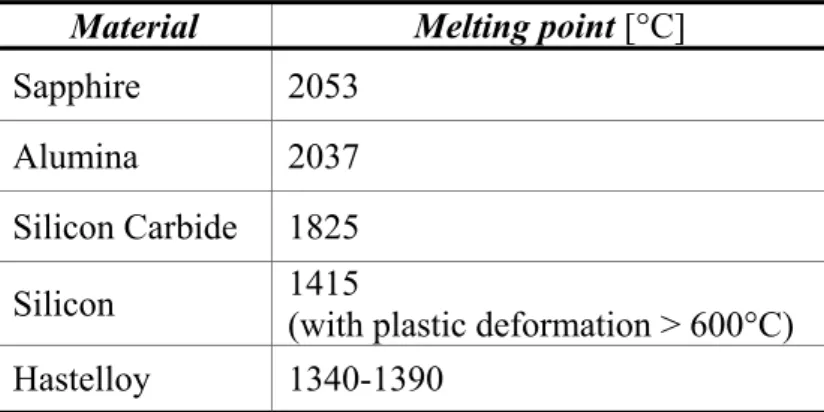
I.5.2.1 Sapphire crystal for combustion applications
The core of the technology is the sensor head which can be fabricated from sapphire (e.g. ODC; [ I-12]). Sapphire is a single crystal aluminium oxide which is the hardest form of the oxide crystals, is chemically inert and is an electrical insular.
Sapphire has been selected largely for its high temperature performance but in addition for its chemical durability and thermal properties which are well matched to suitable packaging materials.
Summering, the sapphire is:
![Fig. I-1: Energy mix of world electricity generation by fuels (reproduced from data in reference [ I-1] and [ I-7])](https://thumb-eu.123doks.com/thumbv2/123dokorg/2838674.4997/28.892.130.763.448.864/fig-energy-world-electricity-generation-fuels-reproduced-reference.webp)
![Fig. I-5: Schematics of axial and radial swirlers ([ I-31], [ I-32]).](https://thumb-eu.123doks.com/thumbv2/123dokorg/2838674.4997/39.892.286.604.767.1057/fig-i-schematics-axial-radial-swirlers-i-i.webp)
![Tab. I-2: Example of parameters of interest for feedback control in Active Combustion Control [ I-48]](https://thumb-eu.123doks.com/thumbv2/123dokorg/2838674.4997/47.892.142.755.197.698/tab-example-parameters-feedback-control-active-combustion-control.webp)