UNIVERSITÀ POLITECNICA DELLE MARCHE
SCUOLA DI DOTTORATO DI RICERCA IN INGEGNERIA DELL’INFORMAZIONE CURRICULUM IN INGEGNERIA INFORMATICA, GESTIONALE E DELL’AUTOMAZIONE
Design of SLAM strategies and technologies in
structured and complex environments
Ph.D. Dissertation of:
Silvia Zingaretti
Advisor:
Dott. Ing. David Scaradozzi
Curriculum Supervisor:
Prof. Francesco Piazza
UNIVERSITà POLITECNICA DELLE MARCHE
DOTTORATO DI RICERCA IN INGEGNERIA DELL’INFORMAIZONE FACOLTà DI INGEGNERIA
iv
To Matteo
v
Table of contents ... v
LIST OF FIGURES ... VIII LIST OF ABBREVIATIONS ... XI ACKNOWLEDGMENTS ... XII ABSTRACT ... XIII SOMMARIO ... XIV CHAPTER 1 INTRODUCTION ... - 1 -
1.1BACKGROUND AND MOTIVATION ... -1-
1.2OBJECTIVES ... -2-
1.3OUTLINE OF THE THESIS ... -4-
CHAPTER 2 STATE OF THE ART ON SLAM ALGORITHMS AND TECHNIQUES ... - 6 -
2.1KALMAN FILTERS ... -10-
2.2PARTICLE FILTERS ... -13-
2.3EXPECTATION MAXIMIZATION (EM)... -15-
2.4GRAPH-BASED SLAM ... -17-
2.5VISUAL SLAM ... -19-
2.6UNDERWATER SLAM ... -23-
2.7CONSIDERATIONS ON SLAM TECHNIQUES ... -26-
2.8VISION SYSTEMS AND TECHNIQUES EMPLOYED FOR MAPPING (PARTIALLY) STRUCTURED ENVIRONMENT -32- 2.9FRAMEWORK DESIGN ... -43-
CHAPTER 3 FIRST CASE STUDY: INSPECTION AND OBSTACLE DETECTION IN INDUSTRIAL ENVIRONMENT ... - 46 -
vi
3.2.1 The vision system ... - 49 -
3.2.2 Point cloud acquisition ... - 52 -
3.2.3 Point cloud registration ... - 54 -
3.2.4 Obstacle detection and results ... - 61 -
CHAPTER 4 SECOND CASE STUDY: BAYER’S CHALLENGE ... - 65 -
4.1THE CHALLENGE ... -65-
4.1.1 Steps to fulfill ... - 66 -
4.2 THE PROPOSED SYSTEM ... -67-
4.2.1 Vision system ... - 69 -
4.2.1.1 Cameras calibration ... - 70 -
4.3ALGORITHM IMPLEMENTATION ... -74-
4.3.1 Seal recognition ... - 75 -
4.3.2 Red cable strap localization ... - 76 -
4.3.3 Results ... - 80 -
CHAPTER 5 UNDERWATER APPLICATIONS ... - 83 -
5.1DOCUSCOOTER ... -84-
5.1.1 Green Bubbles project ... - 84 -
5.1.1.1 Specific Objectives ... - 85 -
5.1.2 Background and Motivation ... - 86 -
5.1.3 DocuScooter architecture ... - 89 -
5.1.3.1 Android app ... - 93 -
5.1.4 VALIDATION AND RESULTS ... - 94 -
5.2BRAVE ... -97-
5.2.1 BRAVe architecture ... - 97 -
5.2.2 Vision Module ... - 99 -
vii 6.2REALIZATION OF OBJECTIVES AND MAIN CONTRIBUTIONS ... -107- 6.3FUTURE WORKS ... -108-
viii
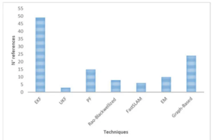
Figure 1 Examined bibliography... - 27 -
Figure 2 Major techniques adopted in SLAM ... - 27 -
Figure 3 Techniques during the years ... - 27 -
Figure 4 Visual SLAM sensor system... - 28 -
Figure 5 Visual SLAM techniques ... - 29 -
Figure 6 Indoor/Outdoor ... - 31 -
Figure 7 Underwater SLAM ... - 31 -
Figure 8 Techniques in Underwater SLAM ... - 31 -
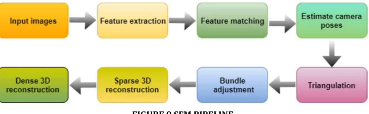
Figure 9 SfM pipeline ... - 34 -
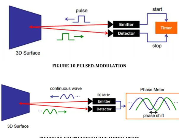
Figure 10 Pulsed-modulation ... - 38 -
Figure 11 Continuous wave modulation ... - 38 -
Figure 12 Bin picking applications ... - 42 -
Figure 13 Framework scheme ... - 44 -
Figure 14 Calibration panel ... - 50 -
Figure 15 Calibration panel captured from left, front and right cameras respectively .... - 50 - Figure 16 Calibration software main screen ... - 51 -
Figure 17 Point cloud calibration ... - 54 -
Figure 18 Point cloud unified ... - 54 -
Figure 19 Main screen ... - 57 -
Figure 20 Point Cloud Library Registration API ... - 58 -
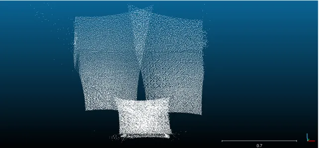
Figure 21 Target and source point clouds ... - 60 -
Figure 22 Aligned point cloud ... - 60 -
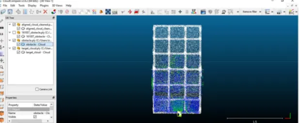
Figure 23 Target and Source point clouds. In red: source, in yellow: target ... - 62 -
Figure 24 Target and Aligned point clouds. In red: aligned, in yellow: target ... - 62 -
Figure 25 Obstacle detected (yellow rectangle) ... - 63 -
ix
Figure 29 Ensenso n35 ... - 70 -
Figure 30 multi camera setup ... - 71 -
Figure 31 linking tree ... - 72 -
Figure 32 cameras calibration result /1 ... - 74 -
Figure 33 cameras calibration result /2 ... - 74 -
Figure 34 yellow seal ... - 76 -
Figure 35 long cable strap ... - 77 -
Figure 36 two pieces of cable strap ... - 77 -
Figure 37 red cable detection ... - 78 -
Figure 38 Main window of red cable strap pipeline ... - 80 -
Figure 39 Point to cut identified ... - 81 -
Figure 40 point to cut identified /2 ... - 81 -
Figure 41 Point to cut identified /3 ... - 82 -
Figure 42 Citizen science project ... - 89 -
Figure 43 Docuscooter architecture ... - 90 -
Figure 44 DocuScooter app ... - 94 -
Figure 45 DocuScooter prototype ... - 95 -
Figure 46 Reconstruction of a pipe from docuscooter test ... - 96 -
Figure 47 reconstruction with trajectory followed ... - 96 -
Figure 48 thrusters configuration ... - 97 -
Figure 49 Compartments assembly ... - 98 -
Figure 50 vision compartment assembly ... - 101 -
Figure 51 Left and right camera calibration ... - 101 -
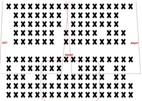
Figure 52 Areas covered by the vision devices aboard ... - 102 - Figure 53 Right camera North-South 3D recunstruction obtained with 112 images ... - 104 -
xi CCD - Charge-Coupled Device
CMOS - Complementary Metal-Oxide Semiconductor COTS - Commercial Off-The-Shelf
ICP – Iterative Closest Point IMU – Inertial Measurement Unit
MIBACT - Ministero dei Beni e delle Attività Culturali e del Turismo PCL – Point Cloud Library
ROI - Region of Interest SfM - Structure from Motion
SLAM - Simultaneous Localization and Mapping STMP – Servizi Tecnici Marittimi Portuali ToF – Time of Flight
xii At the end of this three-years of doctorate I would like to thank you all the people who, in various ways, have accompanied and supported me during this iter with their suggestions and advices and without which this work thesis would not have been possible.
First of all I would like to thank you my academic supervisor, Prof. David Scaradozzi, for being always available to offer me his methodological and scientific contribution during all the phases of the research work and to let me do stimulating and formative experiences for my growth as a PhD.
I would also like to thank my company tutor, Cristina Cristalli, for giving me the possibility of being part of some big and challenging works and showing me the industrial reality in an innovative company like Loccioni Group.
I would like to say a big thank you to my PhD colleagues and friends, Luca, Laura, Lorenzo and Nicolò, with whom I shared lessons, works, preoccupations and frustrations, but also ideas, satisfactions, apartment sharing and… trips!
Lastly, a special thanks to my family for never making me lack moral support. An immense thanks to Matteo, without whom everything would not have been possible. Thank you for being close to me even when we were physically distant.
xiii The research activity has been focused on the study and design of a framework for visual SLAM strategies and technologies, to be applied in robotic systems working in partially structured and complex environments. The framework aims at processing the information coming from the mechatronic subsystems in order to obtain the map of the scene at each instant. In a SLAM problem, in fact, a mobile robot tries to build a map of the environment while simultaneously use it to localize itself. The map can be represented in different ways depending on the sensors used, on the characteristics of the environment and on the estimation algorithm.
Studies about implementation aspects of the SLAM problem in literature have been firstly conducted, in order to properly characterize the entire framework.
Innovative contributions rely on the fact that the proposed framework could have impact on various target groups: it is not designed for a specifically application, but it can be adapted to various scenarios and working environment.
Additional contributions consisted in the intensive adoption of a Computer vision and 3D imaging approach to process and elaborate the sensors information into a useful 3D model. The combination and fusion of many sensors is introduced to exploit the complementarity of each one and increase the accuracy of the 3D model.
The framework subsystems have been customized for its validation in two different environments: two real industrial processes and two real underwater applications have been used as testing situations. In each scenario the number and the type of sensors chosen are different, accordingly to the tasks that the specific robotic system has to perform. Each situation is characterized by a different robotic system and the results have been discussed.
xiv L’attività di ricerca ha riguardato lo studio e la progettazione di un framework intorno alle strategie e alle tecnologie del Visual SLAM, per essere applicato sia in sistemi robotici in ambienti parzialmente strutturati che in quelli complessi. Il framework ha l’obiettivo di processare le informazioni provenienti dai sottosistemi meccatronici di cui è costituito in modo da ottenere la mappa della scena in ogni istante. In un problema di SLAM, infatti, un robot mobile cerca di costruire la mappa dell’ambiente in cui si muove ed usarla per localizzare se stesso. La mappa può essere rappresentata in diversi modi in base ai sensori utilizzati, alle caratteristiche dell’ambiente e agli algoritmi di stima impiegati.
Sono stati inizialmente condotti studi riguardo gli aspetti implementativi del problema dello SLAM affrontati in letteratura con lo scopo di caratterizzare il framework in maniera appropriata.
Contributi innovativi di questa ricerca hanno riguardato il fatto che il framework proposto può avere un impatto su differenti gruppi di end-users: non è stato progettato per un’applicazione specifica, ma può essere adattato a vari scenari e diversi ambienti di lavoro. Altri contributi sono costituiti da un uso intensivo di tecniche di Computer Vision e 3D Imaging per processare ed elaborare le informazioni provenienti dai sensori in un efficiente modello 3D. La combinazione e la fusione di più sensori sono utilizzate per sfruttare le complementarietà di ognuno e aumentare così l’accuratezza del modello 3D.
I sottosistemi del framework sono stato poi personalizzati per la validazione in due ambienti diversi: due processi industriali reali e due applicazioni subacquee sono state utilizzate come situazioni di test. In ogni scenario il numero e il tipo dei sensori scelti sono differenti in base ai compiti che lo specifico sistema robotico deve compiere. Ogni situazione, infatti, è caratterizzata da un diverso sistema robotico e i risultati ottenuti sono stati discussi.
- 1 -
Chapter 1
I
NTRODUCTION
1.1
B
ACKGROUND ANDM
OTIVATIONRobotics systems share common aspects: the physical world in which they are situated, the use of sensors to comprehend the environment, and its manipulation through actuators. Their most outstanding characteristic is that they operate in increasingly unstructured environments, which are inherently unpredictable, and one of the fundamental requirements is the ability to navigate within it. As a result, robotics is moving into areas where sensor input becomes increasingly important, and where robot software should be robust enough to cope with a range of situations.
Visual inspection and quality control were performed, and in some case still are, by human experts but their performance is susceptible to various factors. In fact, they are slower than the machines and get tired quickly when they perform long and routine tasks. Moreover, they require training and may need time to develop the right skills. In certain applications, precise information must be quickly or repetitively extracted and used (e.g., target tracking and robot guidance) and in some environments (e.g., underwater inspection, nuclear industry, chemical industry etc.) inspection may be difficult or dangerous. Moreover, nowadays most of the robotic applications need to be totally autonomous in their tasks.
Simultaneous Localization and Mapping (SLAM), also known as Concurrent Mapping and Localization (CML), is the process by which a mobile robot can build a map of the environment and at the same time use this map to compute its location. In recent years, the SLAM problem has received considerable attention by the scientific community, and
- 2 - a flurry of new algorithms and techniques has emerged, which can be categorized in mainly two approaches: on-line and full SLAM.
A robot is usually equipped with internal sensors that are used to perceive its position, pose and motion parameters. The vision sensors made considerably huge progress since its first uses. The progress made has been principally on two separate fronts: vision-based navigation in structured environments, where the geometrical characteristics of the environment are known, and vision-based navigation for complex environments, e.g. outdoor.
Most of vision-based systems are monocular and binocular, although those based on trinocular configurations also exist. For those systems, a sub set of methodology has been studied and presented with the keyword of visual SLAM. Usually, these systems apply algorithms used in the Computer Vision community for Structure from Motion (SfM). SfM has become an emergent methodology in the recent decades; it estimates the camera poses and the scene structure simultaneously without requirement for any previous knowledge, from the information about common points visible in the images. The accuracy of this technique depends on many factors like the resolution of the adopted camera, the working distance, the light conditions, etc., and so sometimes it is too variable, particularly if working in industrial environments.
In the recent years, roboticists are starting to use 3D vision sensors in their applications, and in particular on a new generation of active cameras based on the Time-of-Flight (ToF) principle. The ToF-sensor is a very compact device which allows to acquire data at high frame rates and to obtain 3D point clouds without scanning. Although the use of ToF cameras have several advantages in respect of the stereo systems, the resolution of their depth maps is far below the stereo depth maps and the measurements are greatly corrupted.
- 3 - The Ph.D. research activity described in the present dissertation has been funded by a project sponsored by a cooperation between Università Politecnica delle Marche (Dipartimento di Ingegneria dell’Informazione - DII) and Loccioni Group, an Italian company based on Marche region, that develops, measures and tests solutions to improve the quality of products and processes for the manufacturing and service industry
This work arose from the necessity of increasing the capability of scene understanding of a working environment by means of vision sensors. Even if there are other type of sensors that allow a more precise acquisition in many situations, today vision sensors can be implemented in a wide variety of industries and applications, offering cost advantages over standard solutions in difficult sensing environments. To increase the accuracy of data acquisition and the successive elaboration, a combination of different sensors is often introduced to exploit the complementarity of each one, and this concept has been adopted also in the present work.
The aim of this work was to design and develop a framework for visual SLAM strategies and technologies in partially structured and complex environments. This framework is based on mechatronic systems equipped with various high efficient sensors, employed in different robotics applications working in delicate industrial environment or underwater environments. The study, during the three years of activities, considered different optical sensors and the implementation of different techniques to map the environment in which the robot is moving. The information extracted from each sensor at each instant t, t+1, etc., have been merged at high level in order to be employed in SLAM algorithms.
The main objectives of this dissertation can be listed as follows: 1. Design a framework for visual SLAM strategies;
2. Study and develop Computer Vision and 3D imaging techniques to be implemented within the framework, to extract the information from the images acquired and mapping the environment;
- 4 - 3. Implement and validate the framework in different case studies in industrial and
underwater environments for inspection or documentation activities.
The application domain, the tasks to be accomplished, the environment, the speed, etc., play an important role in the design and development of a successful vision system. It is essential to define the requirements of the application domain and to understand what kind of information the machine vision system needs to retrieve and how this is translated into measurements or features extracted from images.
The next chapters will present different application fields of SLAM problems in both partially structured and complex environments, for inspection or documentation activities, detailing the development of vision systems for the extraction and the measurement of the information.
1.3
O
UTLINE OF THE THESISThe contents of this thesis can be divided in three parts. The first part overviews the SLAM techniques most implemented in structured and complex environments, with a focus on those which adopt optical sensors (Chapter 2). The second part include the development of the two vision systems in the context of the industrial case studies, with the partnership of Loccioni Group (Chapter 3 and Chapter 4). Lastly, the last part describes the development of mechatronic systems to be applied in not structured environment, specifically for underwater applications (Chapter 5).
A brief description of each chapter is presented in the following:
Chapter 2, “State of the art on SLAM algorithms and techniques” presents the SLAM algorithms and techniques most used in literature from 1977 to 2017, with a focus on Visual SLAM and on the algorithms applied in underwater environments. It then examines the use of 3D cameras in industrial environments, highlighting advantages and disadvantages, for building the map of the scene.
- 5 - Chapter 3, “First case study: inspection and obstacle detection in industrial environment” presents the first case study: the design and development of a vision system with the use of Time of Flight cameras for an industrial application. The chapter describes the system developed, showing also the results obtained.
Chapter 4, “Second case study: Bayer’s challenge” presents the second industrial application, explaining the context in which it has been implemented and then describing in detail the vision system and the results.
Chapter 5, “Underwater applications” describes two innovative platforms that allow data gathering for documenting and mapping the complex underwater environment, describing their vision systems and the results obtained.
- 6 -
Chapter 2
S
TATE OF THE ART ON
SLAM
ALGORITHMS AND TECHNIQUES
Nowadays robots exercise a high degree of autonomy in a huge amount of different applications. One of the fundamental requirements of an autonomous robot is the ability to navigate within a dynamic, unexplored environment. Navigation can be described as the process of determining a suitable and safe path between a starting point and a goal point for the robot travelling between them [1]. For a successful navigation, it is essential to resolve the following three problems:
• Localization: determining where the robot is
• Goal recognition: determining where the robot has to go
• Path planning: determining how the robot should reach the final point.
To address this purpose, a variety of sensors and techniques has been adopted in literature. The success of a path planning and navigation mission of an autonomous vehicle depends on the availability of both a sufficiently reliable estimation of the vehicle location and an accurate representation of the navigation area. The navigation and localization systems can be mainly divided in two groups: those who need a map of the environment before the navigation starts, with different degree of details depending on the study, and those who are able to build the map while moving. Particularly interesting for this work are the second ones.
Simultaneous Localization and Mapping (SLAM), also known as Concurrent Mapping and Localization (CML), is the process by which a mobile robot can build a map of the environment and at the same time use this map to compute its location, as defined by Tim Bailey and Hugh Durrant-Whyte [2]. Initially, both the map and the vehicle position
- 7 - are not known, the vehicle has a known kinematic model and it is moving through the unknown environment, which is populated with artificial or natural landmarks. SLAM has been formulated and solved as a theoretical problem in a number of different forms. It has also been implemented in many different domains from indoor to outdoor, underwater and airborne systems. A robot starts its navigation in an unknown environment from an unknown location, along a trajectory described by a sequence of random variables, and acquires odometry measurements and observations of the environment while moving. The ability of computing both the map and the robot location is usually due to formulating the statistical correlations between the estimates of the robot position and landmarks, and between those of the landmarks themselves. The overwhelming majority of SLAM algorithms adopts a probabilistic framework that takes advantage of the high degree of correlation between the estimates of individual landmark locations [4] and that tackles the problem of the presence of uncertainty and sensor noise by explicitly modeling different sources of noise and their effects on the measurements [3]. By expressing mapping, so the problem of integrating the information gathered with the robot's sensors into a given representation, and localization, so the problem of estimating the pose of the robot relative to a map, as a joint problem in which the state of the system is composed of both the vehicle pose and every estimated landmark position, it is possible to observe that the correlations grow as the state is updated after each observation.
The problem requires that the probability distribution
P(xk, m | Z0:k, U0:k, x0) (1)
where xk is the state vector describing the location and orientation of the vehicle, m is
the map of the environment (the set of all landmarks), U0:k is the history of control
inputs, Z0:k the set of all landmarks observations and x0 the initial state, is computed at
each instant time. This probability distribution describes the joint posterior density of the landmark locations and vehicle state (at time k) given the complete history of
- 8 - landmark observations and control inputs up to and including time k together with the initial state of the vehicle.
In general, a recursive solution to the SLAM problem is desirable. Given both an observation model and a state transition model, this probability function can be computed using Bayes theorem. The observation model, that describes the probability of making an observation zk when the vehicle location and landmark locations are
known, is in the form
P(zk | xk , m). (2)
The state transition model (motion model) is assumed to be a Markov process where the state xk depends only on the immediately preceding state xk-1 and the applied control
uk, and is independent of both the observations and the map. It is in the form:
P(xk | xk-1, uk). (3)
For calculating the probability distribution of Eq. 1, the two following equations are recursively applied, as stated in [4].
• Time update (Prediction):
, | : , : , = | , × , | : , : , (4)
• Observation update (Correction):
, | : , : , = | , | , | : , : ,
: , :
(5)
Therefore, the estimated landmark locations can be obtained by computing the following conditional density, assuming that the vehicle location is known at every instant:
P(mk|X0:k, Z0:k, U0:k) (6)
Conversely, assuming that the landmark locations are known, the estimate of the vehicle location can be obtained by computing:
- 9 -
P(xk|X0:k, U0:k, mk). (7)
However, in reality the landmark locations and vehicle position are never known with absolute certainty. What is known is that much of the error in the estimated landmark locations is common to all landmarks and arises from the error in the estimated vehicle position. Therefore, this error is highly correlated, which means that the relative location of landmarks may be known with high accuracy, even though the absolute location of the landmarks is quite uncertain [4].
The poses x1:k and the odometry measurements u1:k are usually represented as 2D or
3D transformations while the map can be represented in different ways. Maps can be parametrized as a set of spatially located landmarks, by dense representations like occupancy grids, surface maps or by raw sensor measurements. The choice of a particular map representation depends on the sensors used, on the characteristics of the environment and on the estimation algorithm. Landmark maps [5,6] are often preferred in environments where locally distinguishable features can be identified and especially when cameras are used. In contrast, dense representations [7-9] are usually used in conjunction with range sensors. Independently of the type of the representation, the map is defined by the measurements and the locations where these measurements have been acquired [10;11].
In recent years, the SLAM problem has received considerable attention by the scientific community, and a flurry of new algorithms and techniques has emerged. There are three main paradigms: Kalman Filters (KF), Particle Filters and Graph-based SLAM. The first two are also referred as filtering techniques, which model the problem as an on-line state estimation where the state of the system consists in the current robot position and the map. The estimate is augmented and refined by incorporating the new measurements when they become available. Due to their incremental nature, these approaches are generally acknowledged as on-line SLAM techniques. Conversely, Graph-based SLAM estimate the entire trajectory and the map from the full set of measurements; it is also called full SLAM technique.
- 10 - There is no single best solution to the SLAM problem. The choice of the type of algorithm to use will depend on the peculiarities of the application and on a number of factors, such as the desired map resolution, the update time, the nature of the environment, the type of sensor the robot is equipped with, and so on.
2.1
K
ALMANF
ILTERSThe popularity of the Kalman Filter approaches depends on the fact that it directly provides both a recursive solution to the navigation problem and a means of computing consistent estimates for the uncertainty in vehicle and map landmark locations based on statistical models. In fact, KF relies on the assumption that the next state probability is a linear function in its arguments with added Gaussian noise, the measurement probability must also be linear in its arguments with added Gaussian noise, and the initial belief must be normal distributed. These three properties assure that also posteriors are Gaussian [19]. In practice, the assumptions of linearity are rarely fulfilled. For this reason, two variations of KF are mainly employed in the state-of-the-art SLAM: Extended Kalman Filter (EKF) and Information Filtering (IF), with its extended version.
The EKF overcomes the linearity assumption: the next state probability and the measurement probabilities are described by nonlinear functions [19]. In literature, there exist several examples of the use of the EKF algorithm [13-18,179]. Smith et al. [12] were the first to present the idea of representing the structure of the navigation area in a discrete-time state-space framework, introducing the concept of stochastic map. In [20] authors present an algorithm for the evaluation of the systematic bias error in mathematical model of mobile robot during a 2D SLAM using a combination of recurrent neural network and Extended Kalman Filter. Furthermore, the EKF has been the basis of many recent developments in the field, like in [29].
The Unscented Kalman Filter (UKF) has been developed in recent years to overcome some main problems of the EKF [30]. In the EKF the state distribution is approximated
- 11 - by a Gaussian Random Variable (GRV), which is then propagated analytically through the first-order linearization of the nonlinear system. These approximations can introduce large errors in the true posterior mean and covariance, which can bring to the divergence of the filter. The UKF addresses this problem by using a deterministic sampling approach. The state distribution is again approximated by a GRV but is represented using a minimal set of carefully chosen sample points, called σ-points. These sample points completely capture the true mean and covariance of the GRV, and when propagated through the true nonlinear system, captures the posterior mean and covariance accurately to the 3rd order of the Taylor series for any nonlinearity [27].
Some examples of the use of UKF for navigation and localization can be found in [31,159,186]. The UKF maintains the same order of the computational complexity of the EKF but it increases with the number of landmarks.
An algorithm that significantly reduces the computational requirement without introducing any penalties in the accuracy of the results is the Compressed Extended Kalman Filter (CEKF) [28]. A CEKF stores and maintains all the information gathered in a local area with a cost proportional to the square of the number of landmarks in the area. This information is then transferred to the rest of the global map with a cost that is similar to full SLAM but in only one iteration.
The dual of the Kalman filter is the Information Filter. It is subject to the same assumptions but the key difference arises in the way the Gaussian belief is represented. In the Kalman filter family of algorithms, Gaussians are represented by their moments (mean, covariance), while in information filters by their canonical representation, which is comprised of an information matrix and an information vector. This difference leads to different update equations [19]. There are several advantages of the IF filter over the KF. Firstly, the data is filtered by simply summing the information matrices and vector, providing more accurate estimates [21]. Secondly, the information filter tends to be numerically more stable than the Kalman filter in many applications [19]. But the prediction step of the IF involves the inversion of two matrices: as the state space grows in dimension, the computational complexity increases. So, in this phase,
- 12 - the KF is more advantageous because the update step is additive. Anyway, these roles are reversed in the measurement step, illustrating the dual character of Kalman and Information Filters.
The extended version of the Information Filter (EIF) is analog to the EKF, where the nonlinearities are considered and the parameters of the linear model are replaced by nonlinear functions. Thrun et al. [21] developed a variant of the EIF, the Sparse Extended Information Filter (SEIF), that consists in an approximation, which maintains a sparse representation of environmental dependencies, in order to achieve a constant time updating. This algorithm derives from the observation that the normalized information matrix is sparse: it is dominated by a small number of strong links, and possesses many links whose values, when normalized, are near zero. Furthermore, link strength is related to distance of features: the more distant two landmarks are, the weaker their link is. They were inspired by other works on SLAM filters that represent relative distances, such as Newman’s geometric projection filter [22] and extensions [23], Csorba’s relative filter [24] or Lu and Milion [25] but neither of them are able to perform a constant time updating. Algorithms like SEIF or Ensemble Kalman Filters [160] are well suitable for extension to extremely large-scale settings.
To overcome the difficulties of both EKF and IF, and to be more efficient in terms of computational complexity, a Combined Kalman-Information Filter SLAM algorithm (CF-SLAM) has been adopted in [26]. It is a combination of EKF and EIF that allows executing highly efficient SLAM in large environments.
Although SLAM has been a very active research area in mobile robotics for the last decade, no extensive works on the essential properties of SLAM as an estimation problem have been published. The strongest results concerning the convergence of a SLAM algorithm are available for the Kalman filter based SLAM thanks to Dissanayake et al. [29], who examined a simple linear version of the problem and provided three important properties of SLAM regarding convergence and lower bound on the position uncertainty:
- 13 - • “the decreasing of the determinant of any submatrix of the map covariance
matrix as observations are made successively”;
• “the landmark estimates become fully correlated in the limit”;
• “the covariance associated with any single landmark pose estimate reaches a lower bound determined only by the initial covariance in the vehicle location estimate at the time of the first sighting of the first landmark” [29].
However, the convergence proofs given are only for a linear case, which do not depict any real SLAM implementation. Many authors showed that the EKF-SLAM produces inconsistent estimates [32-36, 39] and it has been pointed out that linearization is the main cause of it [33]. These problems cannot be eliminated but only reduced, as the basic problem is non-linear.
The second widely investigated aspect in SLAM algorithms is scalability. In general, SLAM algorithms should be capable of computing extensive areas, either using a single or multiple robots. Typically, EKF-based approaches to SLAM suffer from poor scalability and have a limited applicability to large maps, since their update stage has a quadratic dependence with the number of features in the map [29]. The common idea underlying most of some more efficient approaches is to decompose the problem of building one large map into a collection of smaller maps, which can be updated more efficiently [21, 28, 41, 42, 43, 161]. Local maps can be then joined together into a global map that is equivalent to the map obtained by the standard EKF-SLAM approach, except for linearization errors. As most of the mapping process consists in updating local maps, where errors remain small, the consistency of the global map obtained is greatly improved.
2.2
P
ARTICLEF
ILTERSParticle filters [9, 30, 40] comprise a large family of sequential Monte Carlo algorithms [45] for calculating posteriors in partially observable controllable Markov chains with discrete time. The key idea of the particle filter is to represent the posterior by a set of
- 14 - random state samples, the so-called particles, drawn from this posterior [19]. Particle filters are attractive to roboticists for different reasons [50]. First, they can be applied to almost any probabilistic robot model that can be formulated as a Markov chain. Secondly, they do not require a fixed computation time but their accuracy increases with the available computational resource. Finally, they are relatively easy to implement: they do not need to linearize non-linear models and do not worry about closed-form solutions of the conditional probability as in Kalman filters. The main limitation of plain particle filters is their poor performance in higher dimensional spaces. In fact, the number of particles needed to populate a d-dimensional space increases exponentially with d, so most successful applications have therefore been confined to low-dimensional state spaces. However, many SLAM problems [46,47,48,49] possess structure that can be exploited to develop more efficient particle filters within applications in higher dimensional spaces.
Some of the EKF limitations mentioned in the previous paragraph have been overcome by particle filters. Recent research [9, 51, 52, 53] has led to a family of so called Rao-Blackwellized particle filters that lead to more efficient solutions. These particle filters require time O(M logN) instead of O(N2), where M is the number of particles. They can
also incorporate negative information, hence make better use of measurement data. Furthermore, they provide a better solution to the data association problem. However, these algorithms are susceptible to considerable estimation inconsistencies because they generally underestimate their own error [56]. In large part this is due to degeneracies in the sampling process. Different sampling strategies to improve the consistency of the filter’s estimation and the diversity of the trajectory samples have been adopted [55,57,58].
A particular case is FastSLAM [6,9,54]: it denotes a family of algorithms that integrates particle filters and extended Kalman filters. FastSLAM exploits the structural property of the SLAM problem [53] that the features estimates are conditional independent given the observations, the controls, and the robot path. This observation leads to define a factored representation of the posterior over poses and maps: as the individual map
- 15 - errors are independent, the mapping problem can be factored into separate problems, one for each feature in the map. FastSLAM uses particle filters for estimating the robot path and, for each particle representing a robot path, uses the EKF for estimating feature locations. It offers computational advantages over plain EKF implementations. The filter maintains posteriors over multiple data associations, not just the most likely one, and this feature makes FastSLAM significantly more robust to data association problems than algorithms based on maximum likelihood data association [54]. Furthermore, it can cope with non-linear robot motion models, whereas EKF-style techniques approximate such models via linear functions. However, the presence of a static parameter (the map) in the state space prevents the particle approximation from converging uniformly in time [62]. To overcome this difficulty, [63] introduced a marginal SLAM algorithm: the key difference relies on the nature of the map which is treated as a parameter used to drive a latent data model. This parameter is estimated by a recursive maximum likelihood procedure, solved in practice by a stochastic gradient algorithm [10]. Consequently, this marginal algorithm provides a point estimate of the map and a particle approximation of the marginal posterior distribution of the robot pose at each time.
None of these approaches, however, offer constant time updating while simultaneously maintaining global consistency of the map. To address it, Paskin [59] applied a thin junction trees to the SLAM problem. Currently, researchers are focusing their efforts on Graph-based SLAM algorithms [81], which present better scalability performance and a more compact approach to SLAM (see paragraph 2.4).
2.3
E
XPECTATIONM
AXIMIZATION(EM)
Another popular technique adopted in literature is the Expectation Method (EM) [60]. It is an efficient iterative procedure to compute the Maximum Likelihood (ML) estimate in the presence of missing or hidden data. Each iteration of the EM algorithm consists of two processes: the E-step and the M-step. In the expectation, or E-step, the missing data are estimated given the observed data and current estimate of the model
- 16 - parameters. In the M-step, the likelihood function is maximized under the assumption that the missing data are known. The estimate of the missing data from the E-step are used in place of the actual missing data. Convergence is assured since the algorithm is guaranteed to increase the likelihood at each iteration. A real-time implementation of this algorithm is described in [61].
Expectation algorithms require the whole data be available at each iteration; for this reason, when processing large data sets or data streams, it becomes impractical. As a solution to this, an online version has been implemented [64], where there is no need to store the data since they are used sequentially. The online E-step is divided into a sequential Monte Carlo step and a stochastic approximation step, which incorporates the information brought by the newly available observation. Therefore, each iteration of the online EM-SLAM provides both a particle approximation of the distribution of the pose and a point estimate of the map. This algorithm has been used also to relax the assumption that the environment in many SLAM problems is static. In fact, at present, most of the methods existing in literature are robust for mapping environments that are static, structured, and limited in size, while mapping unstructured, dynamic, or large-scale environments remains an open research problem. The directions followed in literature are mainly two. The first tries to partition the model into two maps: one map holds only the static landmarks and the other holds the dynamic landmarks [65,66]. The second approach, instead, tries to track moving objects while mapping the static landmarks [67,68]. In [69] authors propose a new SLAM algorithm for non-stationary environments which makes use of a new storing structure, the Histogram Occupancy Grid. The Variational Bayesian Expectation Method (VBEM) algorithm can deal with unknown number of landmarks and can tackle the uncertainties in the data associations efficiently. In [70] a radar map is built assuming known trajectory of the sensor; the VBEM translates an inference problem to an optimization one and it is guaranteed to find a local optimum. Authors in [71] developed a whole SLAM solution by means of that. This method is computationally efficient and easy to implement.
- 17 -
2.4
G
RAPH-
BASEDSLAM
Graph-based SLAM models the SLAM system as a graphical structure. Formulating SLAM in a smoothing context adds the complete trajectory into the estimation problem and postpones the mapping process until the end, thus offering improved performance. While this does not seem intuitive at first, because more variables are added to the estimation problem, the simplification arises from the fact that the smoothing information matrix is naturally sparse, as observed by Golfarelli, Maio and Rizzi [72]. Adopting a graphical formulation is an intuitive way to address the full SLAM problem. Solving a graph-based SLAM problem involves building a graph whose nodes represent robot poses or landmarks, linked by soft constraints established by sensor measurements [73]. Relaxing these constraints yields the robot's best estimate for the map and the full path. Thus, in graph-based SLAM the problem is decoupled in two tasks. The first refers to the identification of the constraints from the raw measurements and the construction of the graph. Obviously, such constraints can be contradictory since observations are always affected by noise. The graph construction is usually called front-end and it is heavily sensor dependent. The second problem is to correct the poses of the robot to obtain a consistent map of the environment given the constraints. This part of the approach is often referred to as the optimizer or the SLAM back-end. So, once such a graph is constructed, the crucial problem is to find a configuration of the nodes that is maximally consistent with the measurements. This involves solving a large error minimization problem [90].
These techniques have been firstly introduced by Lu and Milios [25], who represented the SLAM problem as a set of links between robot poses. The map is then refined by globally optimizing the system of equations to reduce the error introduced by constraints. Bosse et al. [74] developed the ATLAS framework, which used multiple connected local maps to integrate global and local mapping, limiting the representation of errors to local regions and adopting topological methods by which local submaps can be managed to provide a global map. Specifically, it consists of a two-level hierarchy of
- 18 - graphs and employs a Kalman filter to construct the bottom level. Then, a global optimization approach aligns the local maps at the second level. Similarly, Estrada et al. proposed Hierarchical SLAM [75] as a technique for using independent local maps and the work of Nüchter et al. [76] aims at building an integrated SLAM system for 3D mapping.
Gutmann and Konolige [77] proposed an effective way for constructing the network and for detecting loop closures while running an incremental estimation algorithm. Folkesson and Christensen [78,79] exploited the optimization perspective of SLAM by applying gradient descent to the log-likelihood version of the SLAM posterior. Their algorithm reduced the number of variables to the path variables when closing the loop and this reduction significantly accelerated gradient descent. Olson et al. [80] likewise presented an efficient optimization approach which is based on the stochastic gradient descent and can efficiently correct even large pose-graphs. Grisetti et al. proposed an extension of Olson’s approach that uses a tree parametrization of the nodes in 2D and 3D. In this way, they increase the convergence speed [81]. Konolige [82] and Montemerlo and Thrun [83] introduced conjugate gradient into the field of SLAM, which is more efficient than gradient descent. Both also reduced the number of variables when closing large cycles. GraphSLAM [84] applies variable elimination techniques to reduce the dimensionality of the optimization problem. In this way, it can handle large number of features and obtains the map and the robot path by resolving the constraints into a globally consistent estimate. The nonlinear constraints are linearized and the resulting least squares problem is solved using standard optimization techniques.
The error minimization in the constraint network has been addressed with many approaches. For example, Howard et al. [85] apply relaxation to localize the robot and build a map. Frese et al. [86] proposed a multi-level relaxation (MLR), which applies it at different resolutions. Dellaert and Kaess [87] were the first to exploit sparse matrix factorizations to solve the linearized problem in full SLAM. Subsequently Kaess [88] presented iSAM, which performs fast incremental updates of the square root
- 19 - information matrix to compute the full map and trajectory at any time. However, to remain efficient and consistent, iSAM requires periodic batch steps for variable reordering and re-linearization, even it is computational expensive. The Bayes tree proposed in [89] provides higher efficiency while retaining sparseness and full accuracy. The Bayes net is the equivalent of the square root information matrix but it allows a fluid re-linearization of a reduced set of variables.
2.5
V
ISUALSLAM
In the SLAM problem, a variety of sensors could be adopted. A robot is usually equipped with internal sensors that are used to perceive its position, pose and motion parameters. In addition to these, other sensors are usually added in order to improve the performances. The progress made in vision-based navigation and localization for mobile robots up to the late 90’s was widely surveyed by DeSouza and Kak in [119]. After the late 90’s, some authors have hardly surveyed this area [120,121]. Most vision-based systems are monocular and binocular (stereo), although those vision-based on trinocular configurations also exist [91].
In literature, different works that make use of monocular cameras can be found [92,176,177]. Blesser et. al. [93] developed an algorithm for a single self-tracking camera operating in a stable natural environment. The system estimates the motion between frames, which is then used to predict which features should be visible to match them. Then, triangulation is used to compute the 3D position of the features and matching is refined by adding epipolar constraints. They demonstrated that this approach successfully localized the camera in small, feature-rich environments but they suggested that the closure of large loops may not be possible as the feature matching has a strong dependence on the motion estimation, which is susceptible to drift. Overall, this approach is remarkably similar to that of Montiel et. al. [94] except that Montiel used simple image patches, represented feature locations by direction and inverse depth and initialized features as semi-infinite lines.
- 20 - The Shi and Tomasi algorithm [96] is adopted in [97] to extract the position of the image features which are used as landmarks to guide the navigation process. The use of a wide angle camera improved some aspects: camera motion can be better identified, with particular improvements on rotational and translational movements estimation, the range of movements increase, and large motions or motions with great acceleration are better dealt with, since they appear much less abrupt. Pinies et. al. [99] investigated the benefits of using a low cost IMU to aid an implementation of inverse depth monocular SLAM similar to that of Davison [97]. They demonstrated that the inertial observations constrain the uncertainty of the camera pose which improves the accuracy of the estimated trajectory [99]. Large-scale direct monocular SLAM [100] is an algorithm that uses only RGB images from a monocular camera as information about the environment and sequentially builds topological map. The main property is the ability of reconstructing 3D environments and direct nature process. To improve the accuracy of the features, some works rely on a multi-sensor system, like the one presented by Castellanos and Tardos [41]. Their system consists of a 2D laser scanner and a camera, implementing an EFK-SLAM algorithm. Laser scanners and vision sensors, particularly monocular vision, have quite orthogonal and complementary properties. Hence, it is meaningful to use laser data to estimate the location of the features and to use the vision data to make these features more distinguishable in the data association process [179]. Other examples of the use of EKF in visual SLAM can be found in [95,179,180].
In recent years, an increasing use of Time of Flight (TOF) cameras has been seen, particularly in structured environment as described in paragraph 2.8. Due to the fact that these cameras give directly the 3D coordinates of the image pixels, authors believe that they can help to have a better reconstruction of the environment [101]. Another structure that is gaining popularity because of its advantages is the omnidirectional cameras. Omnidirectional cameras have a 360◦ view of the environment and given that the features stay longer in the field of view, it is easier to find and track them [162,163].
However, the use of a monocular system can lead to failure modes due to non-observability, problems with scale propagation and requires extra computation to
- 21 - provide depth estimates. To avoid these issues, different works employ a stereo pair. Stereo systems are hugely adopted in different environments, for both landmark detection and motion estimation [102,174,175] in indoor [164-169] and outdoor environments [170-172]. The outstanding work of Sim et al [103,104] implemented a Blackwellised particle filter with the stereo vision system. It implemented a hybrid approach consisting of 3D landmarks extraction for localization and occupancy grid construction for safe navigation. Other examples of the adoption of particle filter algorithms with stereo vision system can be found also in [181,182].
Schleicher et al [105], instead, used a top-down Bayesian method to perform a vision-based mapping process consisting in the identification and localization of natural landmarks from images provided by a wide-angle stereo camera. Simultaneously, a self-localization process is performed by tracking known features of the environment. The authors proved that, thanks to the redundancy of the information extracted from both cameras, robustness and accuracy are increased and the processing time decreased. [106] presents two vision-based SLAM approaches that use 3D points as landmarks: one relies on stereovision, where the landmark positions are fully observed from a single position, and a bearing-only approach that exploits monocular sequences. The relative SLAM system presented in [173] combines a world representation enabling loop closure in real-time with low level image processing adapted to stereo image pairs. They integrated three key components: a representation of the global environment in terms of a continuous sequence of relative locations; a visual processing front-end that tracks features with sub-pixel accuracy, computes temporal and spatial correspondences, and estimates precise local structure from these features; and a method for loop-closure, which is independent of the map geometry. There have been also many successful approaches to the visual SLAM problem using the RGB-D sensor to exploit the 3D point clouds provided [107,178]. RGB-D cameras are sensing systems that capture RGB images along with per-pixel depth information. They rely on either active stereo or time-of-flight sensing to generate depth estimates at a large number of pixels.
- 22 - Most of the visual SLAM systems apply algorithms used in the Computer Vision community for Structure from Motion (SfM). Techniques such as Bundle Adjustment (BA) are in fact generating a great deal of interest in the robotics community now due to the availability of high performance computer hardware and the sparse representations of these techniques can in fact improve performance over the EKF [112]. SfM based techniques typically maintain the full trajectory of the camera and use optimization to find the best trajectory and landmark locations; in paragraph 2.8 an insight of this technique is given. The first real time application of BA was the visual odometry work of Mouragon et. al. [113], followed by the ground breaking SLAM work of Klein and Murray [114], known as Parallel Tracking and Mapping (PTAM). SfM algorithms have been extended to work on long image sequences [115,116], but these systems are fundamentally offline in nature, analyzing a complete image sequence to produce a reconstruction of the camera trajectory and scene structure observed. To obtain globally consistent estimates over a sequence, local motion estimates from frame-to-frame feature matching are refined by means of bundle adjustment. But it has been proven that it is indeed possible to achieve real-time localization and mapping with a single freely moving camera as the only data source [117]. In ORB-SLAM [118], thanks to the covisibility graph, tracking and mapping is focused in a local covisible area, independent of global map size. It is an example of the use of ORB features. Usually, the scale invariant feature transform (SIFT) method, developed by Lowe [109], stands out among other image feature or relevant points detection techniques and nowadays has become a method commonly used in landmark detection applications [108]. SIFT-based methods extract features that are invariant to image scaling, rotation, and illumination or camera view-point changes. During the robot navigation process, detected invariant features are observed from different points of view, angles, distances and under different illumination conditions and thus become highly appropriated landmarks to be tracked for navigation, global localization [110] and robust vision-based SLAM performance [111].
- 23 - A novel visual SLAM approach is illustrated in [122]. It is called Conditional Simultaneous Localization and Mapping (C-SLAM): the camera state transition is derived from image data using optical flow constraints and epipolar geometry in the prediction stage. This not only increases prediction accuracy but also replaces commonly used predefined dynamic models which require additional computation.
2.6
U
NDERWATERSLAM
The underwater environment is extremely challenging and a relevant part of this thesis regards applications employed in it. This paragraph presents a summary of SLAM algorithms and techniques adopted in this environment.
In comparison to the works applied in indoor or in land mobile robotics, there has been little work done in the field of underwater SLAM, mostly due to the complexity of the environment and the difficulty in conducting field experiments. Unpredictable currents and surges acting upon the vehicle body can produce motion in any direction; the lighting conditions are highly dynamic, adding complexity to the motion tracking algorithms; the visibility decreases with depth and turbidity of the water. These are only some of the difficulties that marine researchers need to face. For these reasons, usually a variety of onboard sensors (IMU, depth sensor, etc.) and perception sensors are used to estimate an accurate location and mapping of the subsea habitat. The most used perception sensors in literature are Mechanical Scanned Imaging Sonars (MSIS), Forward-Looking Sonars (FLS), Side-Scan Sonars (SSS) and Video cameras.
There are different examples of underwater SLAM where sonars are employed [146-150]. Mallios et al. [123,124] implemented a SLAM algorithm for partially structured environments were DVL and MSIS are used. Due to the distorted images collected from the MSIS while the vehicle is moving, a two-stage EKF algorithm is implemented: a first EKF is used to estimate the trajectory and then correct the MSIS images; the second stage uses motion estimation and undistorted images once data association is performed. While in [125] a MSIS is used through a modified FastSLAM 2.0 method.
- 24 - Authors in [126] propose a system for mine counter measurement and localization with an AUV where a SSS and a FLS are employed, in addition to the use of the GPS for initial localization. A nonlinear least square optimization is performed to the dead-reckoning (DVL and IMU) sensor and sonar images. In [127] an approach of Graph SLAM is proposed using a set of membership to perform SLAM in a non-linear environment from seamarks located through a SSS.
Vision systems reduce space and cost and increase the resolution, although their range dramatically depends on the water conditions. At present, several solutions for AUVs can be found for many undersea critical applications: undersea infrastructures or installations inspection and maintenance, for any of power, gas or telecommunications transport cases, sea life monitoring, military missions, sea bed reconstruction in deep waters, inspection of sunken ancient ships, etc. Vision has become essential for all these applications, either as a main navigation sensor or as a complement of sonar. Consequently, there exists a good motivation to improve AUVs navigation techniques by expanding their autonomy, capabilities and their usefulness.
Estimation of camera motion in underwater unstructured environments is a tough aspect. If objects like pipes or cables, typical artifacts of interest in underwater operations, are present, the estimation of camera motion is eased. It can be based on edge detectors and Hough transform [128, 129,130] or on different texture groups and segmentation of images in regions with similar textural behavior [131]. In [184] a stereo vision system was integrated in the MARIS intervention AUV to detect cylindrical pipes. Pipe edges are tracked using an alpha-beta filter to achieve robustness and return a reliable pose estimation even in case of partial pipe visibility. Foresti and Gentili [132] implemented a robust neural-based system to recognize underwater objects.
Whereas the environment has no defined references, navigation becomes extremely complicated and challenging. In underwater visual SLAM strategies, features must be found in the overlapping images. There are fundamentally three methods that are used
- 25 - for this purpose: optical flow, feature tracking or gradient methods. Optical flow-based methods and feature tracking can cause failure in algorithms due to scattering effects, bad image quality or lacking illumination under the sea. Gradient methods use scene properties such as depth, range, shapes or color intensity, that are computationally more efficient and more accurate [133].
Pizarro [136] and Eustice [137] developed an information filter based SLAM algorithm that was exactly sparse and operates completely in the information space, thus obtaining linear complexity in the number of landmarks. It was also demonstrated the ability to produce large-scale 3D reconstructions of underwater environments from monocular video and IMU data logged on several ocean surveys. Monocular camera was also employed in [138,152,154,185], while other researchers opted for stereo images systems [139,153,183].
Sometimes, beyond the estimation of the AUV movement through features identification and correlation-based procedures, the grabbed images are combined producing a photo-mosaic of the traveled area [134,151,140]. Marks et al [141,142] developed a technique to implement real-time mosaics using correlation between on-line images and stored images, matching them by edge detection method while [155] used a Fourier based matching. Previous systems often assumed that the seafloor was plane and static, and that the camera was facing it, making the image plane almost parallel to the seafloor plane. Gracias et al [143] proposed a method for mosaicking and localization that did not make any assumption on the camera motion or its relative position to the sea bottom. The system was based on motion computation by matching areas between pairs of consecutive images of a video sequence. Finally, an interesting contribution to underwater mosaicking and positioning was that by Xu and Negahdaripour in [144]. The vehicle position was computed integrating the motion of the camera from consecutive frames using Taylor series of motion equations, including the second order terms, which in previous research was usually ignored. Due to the shortcomings that both sonars and cameras singularly have, is always more frequent to find hybrid systems in literature to enhance the performances [156,157,158]. Mahon
- 26 - et. al. [145] developed an EKF visual SLAM algorithm for an AUV fusing the information coming from both a scanning sonar and high resolution stereo vision system to identify and track a sparse set of distinguishable environment landmarks. They identified that in underwater environments where water movement may quickly cause large uncertainty in the vehicle location it is necessary to have many landmarks to ensure they are always visible. Despite the difficulty of combining two modalities that operate at different resolutions, technology innovations and advances in acoustic sensors have progressively allowed the generation of good quality data suitable for integration, which is usually performed at a feature level [156].
2.7
C
ONSIDERATIONS ONSLAM
TECHNIQUESA total number of 186 works published between 1977 and 2017 have been analyzed to build the state of the art on SLAM. Precisely, the examined bibliography comprises 93 articles from Journals, 86 from Conference, 5 PhD Thesis, as represented in Fig. 1. From a first analysis on which are the techniques and the algorithms most adopted in SLAM problems, it resulted that the majority of the authors implemented the EKF algorithms in their problems (Fig. 2), followed by the Particle Filter. Even the non-filtering technique of Graph SLAM was adopted in a great extent. It can be noticed also that the EKF was adopted continuously from the ‘80s to nowadays while other types of techniques were emerging (Fig.3). It can be stated that the main advantage of the Extended Kalman filter is its ability to provide the quality of the estimate (i.e., the variance), and its relatively low complexity, but it can be applied only for Gaussian and linear models or with limited nonlinearity. Unscented Kalman Filter is a more reliable estimator than EKF when the system model is highly nonlinear, since it approximates the probability density function instead of the nonlinear function itself, as previously described, but it does not make any improvement in the high computational load of the EKF. For this reason, it has not overcome the use of the EKF. For Gaussian and
non-- 27 non-- linear models, particle filtering (PF) is the most appropriate approach, since it is able to provide arbitrarily posterior probability distribution.
FIGURE 1 EXAMINED BIBLIOGRAPHY
FIGURE 2 MAJOR TECHNIQUES ADOPTED IN SLAM
- 28 - The SLAM problems that take into consideration the vision system, the so called Visual SLAM, has been successively analyzed. Within the entire bibliography considered, about 70 articles resulted to use the vision sensor. At first, the analysis on the type of the system adopted was performed. About 50% of the authors employed a single camera, followed by the usage of stereo systems, as illustrated in the graph of Fig.4. Only 7% adopted other types of sensors or composition of the system (i.e. Time of Flight cameras or trinocular systems). Even here the most adopted technique is the EKF, Structure from Motion is also largely used with vision, as it allows to easily detect features in images and so to reconstruct the map of the environment.
- 29 -
FIGURE 5 VISUAL SLAM TECHNIQUES
The largest number of articles applies SLAM in indoor environments (Fig.6). This is due to errors, their magnitude and the unpredictability that make outdoor navigation so much harder than indoor navigation. It is difficult and time consuming to obtain correct and accurate sensory data in such an environment. In fact, measurement errors cannot be avoided and they are often large and with non-standard distribution. As outlined in paragraph 2.6, a few number of works have been conducted in underwater environment in comparison with those in indoor fields. As results from Fig. 7, in underwater scenarios the most used sensor is the vision, followed by sonar sensors. The latter have several disadvantages:
• they usually only allow limited depth for operation, making applications costly for deep immersions;
• the data observed has limited accuracy, particularly in ocean environments where low-light, strong currents and turbid waters are present;
• the estimated noise ends up causing crucial impact on the tasks of localization and mapping, often leading to a non-convergent system.
Cameras turned out to be the most adopted in literature in the last years. It is required to observe as many as possible distinguishable features in order to reduce the uncertainty caused by vehicle drift, so having distinct landmarks could hugely simplify the data association process. They are low cost but with high and accurate data. It is