invisalign treatment in periodondal patient: case report
12
0
0
Testo completo
(2) research article. N. R. II N. ramics that has the same characteristics of resistance of the metal, but that in more ways ties up the advantages to the natural relationship with the light that these materials have (9). With a clean improvement of the final aesthetical result.. TE. Figure 1 Biaxial flexural streght of dental ceramics.. AZ. IO. N AL I. The export of the files is completely opened and therefore compatible with whatever center of productions (millers, CNC, sintering machine or printing 3D). The laser scanner D-250 (Fig. 2) represents the most recent version of the scanners 3D of the 3shape, it provides precise, reliable and quick scanning for dental preparations, bridges, imprints bite, complete arcades and positioning of the fittings. The scanning of a dental preparation happens by using a system of optic scanning. The laser bundles are projected against the object and digital cameras of high resolution digitalis that acquire the images of the lines created on the model or on the stumps. The scanner acquires only the whole geometry of the dental model in a cycle of scanning, without specific necessities of positioning. Automatically the 3shape specific software processes the images and reconstructs completely the models 3D. The elevated precision of scanning includes any under looking present in the original model. Today the market CAD-CAM is in full expansion and proposes a wide choice of materials and solutions (17). The system 3shape allows us for the first time to be able to turn to an only center of production, asking for to realize the device choosing the material on the base of the real demand of the technician, the dentist and of the patient. Thanks to the software it can habitually be produced and personalized both in zirconium and in titanium, compatible with present implanted systems on the market.. IO. N. The CAD-CAM 3Shape system. IC. ED. IZ. The dental system 3shape is a solution CAD-CAM complete and integrated for planning prosthodontic restaurations.. ©. C. CAD Computer Aided Design. Figure 2 Scanner D 250 3 Shape.. The software 3shape CAD Dental Designer (Fig. 3) is optimized for manipulation of frameworks, crowns and bridges, it interfaces natively with the scanner D-250, and it allows the use of whatever miller or utensil machines. The advantage of the use of a software of this type is in the great speed of realization of the projects, in the possi-. ORAL & Implantology - Anno I - N. 3-4/2008. 105.
(3) N AL I. N. AZ. IO. The miller VDM 10.3 (Fig. 4) is fundamentally made from 4 sectors into connected: 1. electronic board (which picks up the data of the phase CAD); 2. milling machine with cutters (diamond drill or tungsten carbide cross cut to avoid that they are mixed) interchangeable; 3. file cutters; 4. base of support for 2 blocks of preformed material, if served of different materials. Board control and the software are connected, they handle all the other sections; In first place it points out the necessary numbers of blocks to get the elaborated demands in rules, accordingly, the fitted type of cutter to get the desired form. To such intention it is to underline well the fact that the preparation won’t have to introduce alive edges. These in fact, also do not represent a problem in phase of reading for a laser scanner, it can constitute a problem in phase of milling since the least diameter of the cutters is of 1mm, and therefore it won’t be possible to realize smaller angles in which the cutters cannot enter. In this case the computer will draw a curve and the residual space in phase of cementation it must be filled with cement.. R. Figure 3 3shape software Dental Designer.. TE. research article. CAM Computer Aided Manufacturing. ©. C. IC. ED. IZ. IO. N. II N. bility to view virtual models 3D without waste of materials, in the absolute repeating of the projects, which realized precision entirely depends on the utensils machines used. For the realization of the crowns with the system 3shape it’s not asked for any particular type of preparation; In theoretical line the frameworks (core) can be realized on any type in profile. The type of preparation to prefer is that to chamfer to smoothed borders and bevels and with a depth of axial workmanship of 1,2-1,5mm. The incisal-occlusal surface must be instead reduced to at least 2mm, to guarantee an enough thickness of alumina or zirconia and aesthetical porcelain. How much more we will succeed in defining the border of the preparation on the tooth and on the stump, so much the scanner will more precisely be able to notice it and to reproduce the image on the screen of the computer. Done this, the files related to the unity of production will be transferred to the miller. Once prepared the tooth, it will proceed to the survey of the imprint and the realization of the model in chalk with the normal procedures. Then fixed on the model in articulated, the stump can be slipped off and prepared for the phases of scanning with the Scanner 3shape.. 106. Figure 4 Milling machine.. ORAL & Implantology - Anno I - N. 3-4/2008.
(4) II N. TE. R. N. AZ. IO. N AL I. research article. N. Figure 5 3shape production cycle.. ©. C. IC. ED. IZ. IO. Besides this the software also manages to speed of advancement and the number of turns of the motor to optimize the cut in terms of quality of the result and rationalization of times. The anticipated time depends on the dimension and conformation of the manufactured article and the material that it intends to mill. Once planned these parameters, the machine automatically realizes (in about a hour) beginning from a measuring block of zirconia (dimensions of 8×5×1,5 cm), and under wide irrigation (using an emulsion of water-gel to 9%), the projected framework, that will come subsequently sectioned by the peduncles of connection that anchors it to the departure blocks, finished and readapted on the model.. Figure 6 The patient, of male sex, healthy and not a smoker, reaches our observation reporting a typical symptomatology pulpitis of the tooth 1.2 (incisive side superior dx). The clinical examination and radiographic endorale put in evidence of an old composite reconstruction infiltrated and over flow of the element that showed besides a conoide morphology.. ORAL & Implantology - Anno I - N. 3-4/2008. 107.
(5) N AL I. IO. AZ. N. TE. R. The patient, of male sex, healthy and not a smoker, reaches our observation reporting a typical symptomatology pulpitis of the tooth 1.2 (incisive side superior dx). The clinical examination and radiographic endorale put in evidence of an old composite reconstruction infiltrated and over flow of the element that showed besides a conoide morphology (Fig. 6).. N. II N. research article. Presentation of a clinical case. In local anaesthesia we proceeded therefore to the canal therapy and subsequently, in the same session, to its reconstruction through a carbon-fiber post and resin composite core (Fig. 7). Done this the tooth was prepared for receiving a provisional crown in resin, directly realized by us to the armchair, and modified in its peripheral contour, being clear wish of the patient to improve the aesthetics of its smile altered by the presence of the conoide (Fig. 8). We attended the conic 21 days of recovery, an imprint of precision was recorded, using gingival displacement cord and a polivinil-siloxano (Fig.s 9, 10).. Figure 9 Tooth ready for precision impression.. ©. C. IC. ED. IZ. IO. Figure 7 Rx after root canal terapy and reconstruction.. Figure 8 Temporary resin crown.. 108. Figure 10 Precision impression.. ORAL & Implantology - Anno I - N. 3-4/2008.
(6) research article. AZ. IO. N AL I. The slip off master model stumps were finally introduced in the cycle of production 3shape (Fig.s 5, 11-17). Once ready the zirconia core, and after a positive test in the oral cable of the patient was thoroughly purposive to a devoted ceramics (with coefficient thermal expiation linear compatible with the zirconium) and returned to the clinician for the definitive cementation To such intention, we remember that such crowns for their characteristics of traslucency and of no transparency can be cemented, in theory with any material.. ©. C. IC. ED. IZ. IO. N. II N. TE. R. N. Figure 11 Master model.. Figures 12-13-14-15 CAD moments.. ORAL & Implantology - Anno I - N. 3-4/2008. 109.
(7) N AL I IO AZ N R TE IO. N. II N. research article. Figures 16-17 CAD moments.. ©. C. IC. ED. IZ. Figure 18 Zirconia framework ready for ceramic.. Figure 19 Zirconia framework tested on master model.. 110. Figure 20 Zirconia crown after cementation.. Analysis of the marginal adaptation of the 3Shape zirconia frameworks Preparation of the models The most greater part of the studies on the marginal precision until now performed has used drawn out teeth or repetitions in epoxy resin of teeth (1).. ORAL & Implantology - Anno I - N. 3-4/2008.
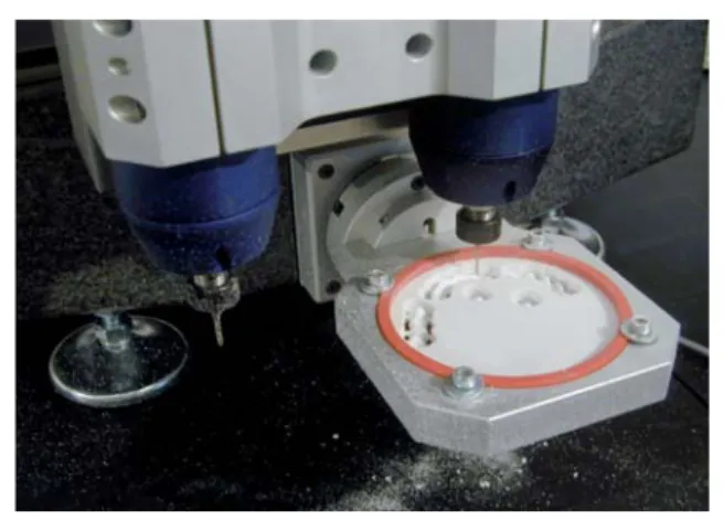
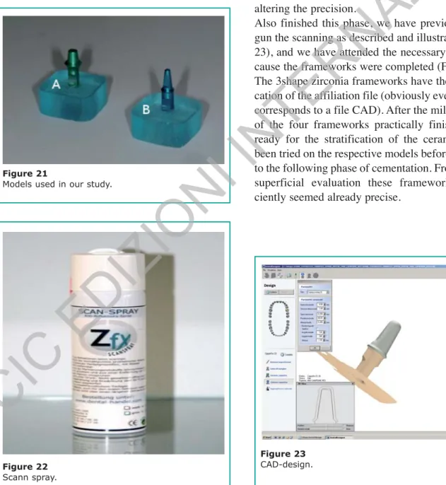
(8) research article. N AL I. Reading of the models. AZ. IO. After having sealed the models, we have begun the first phase of the real job or that related to the scanning. The system 3shape, that we use for reading a laser scanner, obviously is not able to digitize metallic surfaces, because of the reflection and refraction of the reading ray, it has a bad surrender. We have applied therefore with a spray (scan-spray) (Fig. 22) an isolated with zirconium dust that allows the reading of the models without altering the precision. Also finished this phase, we have previously begun the scanning as described and illustrated (Fig. 23), and we have attended the necessary time because the frameworks were completed (Fig. 24). The 3shape zirconia frameworks have the specification of the affiliation file (obviously every frame corresponds to a file CAD). After the milling each of the four frameworks practically finished and ready for the stratification of the ceramics, has been tried on the respective models before passing to the following phase of cementation. From a first superficial evaluation these frameworks sufficiently seemed already precise.. II N. TE. R. N. Our school for years has been using a proper protocol for the study of the obtainable marginal precision with the various systematic CAD-CAM (10). To get the best possible standardization, limiting the least to human factor, our industrially protocol foresees the use of pre-packaged models, with standardized geometry (Fig. 21). These models introduce a shoulder of 1,5 mm to 50° on the whole circumference, a taper of 3° for side and a height respectively of 5 and 8 mm.. ©. C. IC. ED. IZ. IO. N. Figure 21 Models used in our study.. Figure 22 Scann spray.. Figure 23 CAD-design.. ORAL & Implantology - Anno I - N. 3-4/2008. 111.
(9) N AL I IO AZ. 25), the excesses of cement has been removed with a probe, and the models have been prepared to be englobed in transparent resin episodic (E227 Prochima) (Fig. 26).. TE. After the roughing out of the frameworks they have finally been finished up through grit blasting with dust of alumina of 50um to the pressure of 6 atm.. R. N. Figure 25 Zirconia frameworks after cementation.. II N. research article. Figure 24 Zirconia frameworks.. Realization of the sections. For the cementation of the zirconia frameworks doesn’t exist any precise indications. As a rule, either adhesive cementation, or traditional cementation type, they are clinically acceptable even if in reality the best results in terms of resistance to the fracture have been gotten with a resinous cement (Panavia 21). However, the authors’m preference, according to several in vitro studies, is to use an adhesive cementation whenever possible, especially in posterior areas to enhance fracture resistance. The 4 frameworks of our study have been cemented on the respective models with a vetro-ionomeric cement (Ketac-Cem Ap-plicap, Espe). The use of this type of cement is not casual, but dictated by the wish to standardize this procedure, eliminating the manual phases of mixing, also for the phase of cementation. After having prepared the cement, the frameworks have been therefore manually positioned on the models, and subsequently submitted to a constant static load of 5kg (around 50N) for 7 minutes (Fig.. Completed the hardening of the resin (about 24h), the cylinders have been cut with sectioning microtome of the Buehler Isomet Plus (Fig. 27). For every cylinder a section has been performed in. ©. C. IC. ED. IZ. IO. N. Cementation of the frameworks. 112. Figure 26 Models inglobed in epoxid resin.. ORAL & Implantology - Anno I - N. 3-4/2008.
(10) research article. N AL I. photographed to reflected light with the aid of a microscope type Axiophot of the Zeiss, at first to small enlargements and subsequently to greater enlargements (Fig.s 29, 30). In this way the final value of the obtainable marginal gap with the system 3shape has been calculated as average values gotten for every individual model. The equation applied for measuring the present gap to the interface model cappetta has been the following:. Mycroscopic analysis. (1000/enlargement) × 100 = varying μ. Figure 29 Marginal area at 200 enlargements.. ©. C. IC. ED. IZ. Figure 27 Microtome.. IO. N. II N. TE. R. N. To complete this job without any statistic pretension we have analyzed from a microscopic point of view the sections. These are been observed and. AZ. IO. hallway-lingual sense, to level of the median line, producing in this way two side “slices” that has subsequently been shined with a polishing machine model Buehler Metaserv Grinder Polisher with dusts of decreasing Alumina (1-0,3-0,05 microns) (Fig. 28).. Figure 28 Model sections.. Figure 30 Marginal area at 50 enlargements.. ORAL & Implantology - Anno I - N. 3-4/2008. 113.
(11) Average. Model 1. 50,81-62,81. 83,93-110,44. 76,99. Model 2. 90,31-87,30. 54,45-66,78. 74,71. IC. ED. IZ. IO. To the light of the results gotten by our searches, and made comparison to the numerous studies in literature (6-8, 12-14), it seemed to us that we were able to affirm with calm that the aforesaid systematic computerized CAD-CAM represents nowadays a valid alternative to the traditional prosthodontic rehabilitative technique. As we well know, a good marginal closing has: To create a hermetic seal that opposes to bacterial penetration, to restore a correct profiles of emergency, and to prevent the dissolution of the cement. An excessive marginal discrepancy exposes in fact the cement to the action of the oral fluids causing the dissolution of it. To such intention, in 1971 McLean and coll. (21) have held under observation clinical 1000 crowns for five years, reaching the conclusion that an equal or inferior marginal crack to 120 microns is clinically verifiable. Analogous studies entirely performed on crowns. C. N AL I. II N N. Conclusions. ©. IO. AZ. Side B-B1. R. Side A-A1. N. Results. Total average: 78,85 microns. 114. of ceramics have often underlined middle values of the marginal crack inferior to 155 microns, however included in intervals 0-313 microns. A greater number of Dentists therefore, today are in agreement to hold clinically acceptable a marginal crack tablet between 40 and 100 microns. Particularly the systematic 3shape looks very well for what concerns the degree of obtainable marginal precision with the zirconia frameworks, bringing a value of middle marginal gap of the order of-70um, for which well below the limit of clinical acceptability. So far we are able to hold to enumerate such systematic among those in the workmanship of the zirconia, introducing besides the notable advantage to eventually furnish, on application of the physician, an intermediary substitute in resin, to clinically test before directly proceeding to the completion of the definitive job (with a test directly from the armchair onto the patient) particularly suitable in the complex cases. Such systematic results has been particularly interesting for its great versatility that allows it to get, besides the zirconia frameworks, in gold league or cromocobalto, even more complex structures (to more elements bridges) and implant abutments in zirconia or titanium.. TE. research article. Subsequently gotten the value for the varying μ it has been divided for the express length in millimeter of the present nick as reference on all the photos, getting in this way the equivalent value in micron responds to every millimeter. The real measurements have finally been performed on photographic reproduction using a measurer with nick millimetred, for every value a verification has been effected to different enlargements.. References 11. Abbate M, Tjan A, Fox W. Comparison of the marginal fit of various ceramic crown systems. Journ Prosth Dent 1989; 61: 527-531. 12. Andersson M, Oden A. A new all ceramic crown. A dense sintered, high-purity alumina coping with porcelain. Acta Odontol Scand 1993; 51: 59-64. 13. Andersson M, Razzoog ME, Oden A, Hegenbarth E, Lang B. PROCERA: un nuovo modo di produrre una corona in una sola ceramica. Quintessence Intern. 5/6 1999. 14. Arcidiacono A, Arcidiacono A, Scotti R. Ceramiche integrali alluminose. Integrazione tra tecnologia CADCIM e procedure convenzionali. PROtech 2000; 2: 517. 15. Arcidiacono A, Arcidiacono A, Scotti R. Una nuova sistematica CAD-CIM per ponti e corone singole. Dental Cadmos 2001; 3: 43-53.. ORAL & Implantology - Anno I - N. 3-4/2008.
(12) research article. 19.. 20.. N AL I. TE. 21.. IO. 18.. AZ. 17.. N. 16.. R. 15.. ©. C. IC. ED. IZ. IO. N. Correspondence to: Dott. Giovanni De Vico Tel: +39-06-20900268 E-mail: [email protected]. 14.. All-Ceram crowns. The Journal of Prosth Dent 1998; 80: 450-456. Pera P, Gilodi S, Bassi F, Crossa S. In vitro marginal adptation of alumina porcelain ceramic crowns. Journ Prosth Dent 1995; 74: 223-229. Riquier R. CAD/CAM: Scanner a confronto. Quintessenza Odontotecnica 2008; 3: 61-72. Sulaiman F, Chai J, Jameson LM et al. A comparison of the marginal fit of In-Ceram, IPS Empress, and Procera. Int J Prosthodont 1997; 10: 478-484. Stolz K, Kuhn T. L’uso del CAD-CAM in odontoiatria restaurativi. Teamwork anno IX 4/2007; 20-29. Wagner W, Chu T. Biaxial flexural streght and indentation fracture toughness of three new dental core ceramics. The Journ of Prosth Dent 1996; 76: 140-144. Wagner W, Chu T, Razzoog M. Indentation fracture toughness of three new ceramic core materials. Journ Dent Res 1995; 74: 471 (abstract). Zeng K, Oden A, Roweliffe D. Flexure tests on dental ceramics. International J Prosth 1996; 9: 434-439. Mc Lean J, von Fraunhofer J. The estimation of cement film thikness by an in vivo technique. British Dent Journ 1971; 131: 107-111.. II N. 16. Bergman B, Nilson H, Andersson M. A longitudinal clinical study of Procera ceramic veneered titanium copings. Int Journ Prosth 1999; 12: 135-139. 17. Brix O. Impiego della ceramica integrale. Arte ed esperienza. PROtech 2002; 5: 31-39. 18. De Vico G, Barlattani A, Sommella A. Estetica in protesi fissa: solo metal free..?!. Teamwork anno IX; 2007; 4: 70-82. 19. Fradeani M, Corrado M. Ottimizzazione estetica dei restauri anteriori. Ruolo dei materiali ceramici. Dental Cadmos 1999; 16: 11-28. 10. Gargari M, De Vico G, Ottria L, Barlattani A. Sistematiche computerizzate per l’estetica in protesi fissa. Procera-all Ceram. Quintessenza Internazionale 2004; 1: 77-88. 11. Hickel R, Dasch W, Mehl A, Kremers L. CAD-CAM: filling of the futute?. Intern Dent Journ 1997; 47: 247258. 12. La Manna O, Battistelli A, Severino D, Pozzi A. Estetica e precisione nelle ceramiche integrali pressofuse. Dental dialogue anno XI 2/2004. 13. Oden A, Andersson M, Krystek-Ondracek I, Magnusson D. A 5 year clinical follow-up study of Procera. ORAL & Implantology - Anno I - N. 3-4/2008. 115.
(13)
Figura
Documenti correlati
Up to now this class of low power thrusters has not been deeply studied, in fact, only recently there is a great interest to mini and micro satellites that ask for thruster
The recycling with screening of fine powders and the recharge seems the best way to reuse the abrasive but it isn’t surely the only one: since the particles of the recycled
On the one hand, a change in the house value tends to generate rather illiquid effects, because real estate is usually traded in markets plagued by high frictions and pervasive
This result strongly suggests that we are observing discrete shifts from part-time to full-time work, as conjectured by Zabalza et al 1980 and Baker and Benjamin 1999, rather
In particular, generational accounting tries to determine the present value of the primary surplus that the future generation must pay to government in order to satisfy the
This slight change yielded better results than the keywords used in the other databases.This is a review of in vitro studies which evaluated the effect of change in
Although it was hypothesized that higher acidity would induce higher corrosion, which would be seen in increase of surface roughness, friction and decrease of microhardness it was
The novelty of the thesis mainly resides in the use of novel data-sets, the careful analysis of the impact of the Great Recession on the labour markets of the
