Ph.D. Thesis in Structural Engineering
(XXXI)
Ph.D. Candidate:
Giorgia Di Gangi
Structural Analysis and Design of
Timber Light-Frame shear walls
Ph.D. Coordinator:
Prof. Franco Bontempi
Tutor:
Prof. Giorgio Monti
Acknowledgments
First and foremost I want to thank people who shared with me tough and exciting times, starting from my family: my very patient boyfriend, my beloved father, mother and brother, who have never stopped encouraging and stimulating me, following my path also dur-ing my stay abroad in China.
I am grateful to Prof. Giorgio Monti, who believed in me and shared his enthusiasm and time, giving me the illuminating suggestions that guided the development of the work presented in this thesis.
Furthermore I am grateful to Cristoforo Demartino, who first trasmit-ted me the passion for programming, and to Giuseppe Quaranta for his precious advices along with patient and constant support to im-prove my skills and work.
My sincere thanks also go to everybody who supported me during the experimental tests: Prof. Yan Xiao in China, at the laboratory of Nan-jing Tech University, and Marco Vailati along with Silvano Silvani in Italy at the laboratory of Sapienza located in Valle Giulia.
My time during my Ph.D. was made enjoyable also thank to many friends and colleagues I spent time with.
Finally, I would like to thank Prof. Natalino Gattesco and Dr. Ingrid Boem (University of Trieste, Italy) for having shared the data of the experimental tests reported in (Gattesco and Boem, 2016).
1 Introduction 15
1.1 Modern approach for building design . . . 15
1.2 The concept of green building . . . 16
1.2.1 Wood and bamboo as environmentally-friendly materials . . . 17
1.3 Goals and original contributions of the thesis . . . 19
1.4 Layout of thesis . . . 20
2 Timber Light-Frame buildings 24 2.1 Code framework . . . 25
2.2 Timber classification . . . 27
2.3 Construction systems . . . 28
2.3.1 Balloon- and platform-frame construction systems 29 2.3.2 Panel construction system . . . 31
2.4 Basic elements . . . 32
2.4.1 Wall frame . . . 34
2.4.2 Exterior walls: cross junctions . . . 34
2.4.3 Exterior walls: openings . . . 35
2.4.4 Floor frame . . . 35
2.4.5 Roof frame . . . 36
3 Timber Light-Frame shear walls: geometry and me-chanics of basic elements 39 3.1 Frame . . . 39
3.1.1 Headers for openings . . . 41
3.2 Sheathing panels . . . 41
3.2.1 Plywood panels . . . 42
3.2.2 Oriented StrandBoard (OSB) panels . . . 42
3.3 Connections for wood-based buildings . . . 43
3.3.1 Nails . . . 43
3.3.2 Hold-downs . . . 48
4
4 Timber Light-Frame shear walls: sheathing-to-framing
connections 51
4.1 Fasteners classification . . . 51 4.2 Background . . . 52 4.3 Mechanical behavior according to the EuroCode 5 . . . 54 4.3.1 Characteristic yield moment of fastener . . . 55 4.3.2 Interface properties: embedment strength . . . . 57 4.3.3 Interface properties: withdrawal strength . . . . 58 4.4 Mechanical model of fastener . . . 59
4.4.1 Definition of lateral stiffness at the SLS and ULS into the EuroCode 5 . . . 59 4.4.2 Mechanical models in literature . . . 61
5 Timber Light-Frame shear walls: review of seismic
analysis and design methods 64
5.1 Seismic Hazard . . . 64 5.2 Direct Displacement Based Design (DDBD) . . . 65 5.3 Equivalent viscous damping . . . 68 5.4 Inelastic demand spectra: Capacity Spectrum and N2
Methods . . . 71 5.5 Ductility of timber structures . . . 72 5.6 Mechanical behavior and modeling of Timber Light-Frame
shear walls: state of art . . . 74 5.6.1 Modeling considering rigid framing elements . . 77 5.6.2 The relevance of flexible framing elements and
shear contribution of the sheathing panel in nu-merical modeling . . . 83 5.6.3 Mechanical behavior with openings . . . 84 5.7 Mechanical behavior and modeling of Timber Light-Frame
shear walls according to the EuroCode 5 . . . 86 5.7.1 Rigid framing elements: the in-plane racking
re-sistance using method A . . . 86 5.7.2 Flexible framing elements: the shear wall as a
composite timber section . . . 87 5.7.3 Mechanical behavior with openings . . . 89
6 Parametric numerical model of a Timber Light-Frame
shear wall 91
6.1 Parametric numerical model without openings . . . 91 6.2 Parametric numerical model with openings . . . 94 6.3 Parametric identification of fastener mechanical model . 95 6.4 Validation of the wall FE model . . . 97 6.5 Sensitivity analyses on wall without openings . . . 102 6.5.1 Method of analysis and loading conditions . . . . 102
6.5.2 Internal releases . . . 104
6.5.3 Aspect ratio . . . 105
6.5.4 Nails spacing . . . 108
6.5.5 Number of vertical studs . . . 109
6.5.6 Cross-section size of framing elements . . . 109
6.5.7 Final comments on results . . . 110
7 Analytical procedure for seismic analysis and design 114 7.1 Mechanical modeling . . . 114
7.2 Single fastener for timber structures . . . 115
7.2.1 Constitutive law . . . 115
7.2.2 Equivalent viscous damping and ductility . . . . 117
7.3 Timber Light-Frame shear wall . . . 117
7.3.1 Definition of the equivalent viscous damping . . 117
7.3.2 Definition of the racking load-carrying capacity . 120 7.3.3 Definition of the ultimate strength . . . 121
7.3.4 Definition of the overall secant stiffness . . . 122
7.3.5 Definition of the analytical backbone F-d curve . 122 7.3.6 Definition of the global ductility and computa-tion of the global ultimate displacement . . . 123
7.3.7 A simplified equation to correlate equivalent vis-cous damping and inter-storey displacement de-mand . . . 123
7.4 Validation of the analytical procedure . . . 125
7.5 Prediction of backbone curve considering the hold-downs contribution . . . 128
8 Optimal configurations of Timber Light-Frame shear walls 132 8.1 Optimum design criteria . . . 132
8.2 Results . . . 133
9 Conclusions and future developments 138 A Appendix 142 A.1 The OpenSees code . . . 142
B Appendix 151 B.1 Connection load-carrying capacity calculations accord-ing to EuroCode 5 . . . 151
C Appendix 156 C.1 Experimental tests: materials and methods . . . 156
C.2 Bamboo . . . 156
C.2.2 Test setup . . . 157 C.2.3 Results . . . 158
D Appendix 161
D.1 Example of global behavior prediction of a Timber Light-Frame shear wall . . . 161
Nomenclature
˜
µf Ductility of the bilinearized F-d curve of fastener ˜
µi Bilinearized ductility of the wall weakest connection ˜
µSH Bilinearized ductility of the sheathing-to-framing connections ˜
µv Bilinearized ductility of the wall (EIy)e f f Effective bending stiffness α Aspect ratio of the wall panel
αf Parameter that identifies the resistance decrement of the con-sidered fastener
αYS Opening area ratio according to Yasumura and Sugiyama (1984)
β Ratio of the characteristic embedment strength of members in the assemblage
βYS Wall length ratio according to Yasumura and Sugiyama (1984) ∆A Horizontal displacement provided by the rigid-body
transla-tion contributransla-tion
∆d Target displacement amplitude
∆H Horizontal displacement provided by the rigid-body rotation contribution
∆i,pl(ui,pl) Plastic displacement of the wall weakest connection ∆i,u(ui,u) Ultimate displacement of the wall weakest connection ∆i,y(ui,y) Yield displacement of the wall weakest connection
∆P Horizontal displacement provided by the shear deformation of sheathing panel
∆SH Horizontal displacement provided by the sheathing-to-framing connections contribution
∆v,y Yield displacement of the wall η Damping factor
γ Coefficient that represents the energy dissipation distribution along the perimeter horizontal joists
γi Connection efficiency factor
γM Partial safety factor
γR,d Over-strength ratio
γs Shear angle
κ Coefficient that represents the energy dissipation distribution along the perimeter vertical studs
λ(α) Shape parameter depending on the aspect ratio of the wall panel
µ Ductility ratio of the structure
µf Ductility of a single fastener (nail)
µi Ductility of the wall weakest connection
µSH Ductility of the sheathing-to-framing connections
ω Frequency of the load
ωn Natural vibration frequency of the system
ρk Characteristic density of timber or LVL
ρm Mean density of timber or timber-based product
τ·l Internal lever arm of the wall panel
ξeq,hyst Equivalent viscous damping correspondent the hysteretic be-havior of the structural system
ξeq Equivalent viscous damping (hysteretic damping)
ξf Equivalent viscous damping of a single fastener
ξin Inherent viscous damping equal to 5%
ξtot Total equivalent viscous damping
˜ED f Dissipated energy under the bilinearized F-d curve of fastener ˜Ff ,Rd Yield strength of the bilinearized F-d curve of fastener
10|Chapter 0
˜Fv,Rd Yield strength of the bilinearized F-d curve of the wall
˜ui,pl Bilinearized plastic displacement of the wall weakest connec-tion
˜ui,Rd Bilinearized yield displacement of the wall weakest connection ˜uv,pl Bilinearized plastic displacement of the wall
˜uv,Rd Yield displacement of the bilinearized F-d curve of the wall A0 Asymptotic strength of fastener
A1 Slip at one half the asymptotic strength of fastener Ahyst Dissipated energy enclosed in one hysteresis loop Ai Cross-section area of the i-th element
ai(zi) Distance between the global Y-axis of the whole cross-section and the i-th local y-axis
bi Panel width
c Damping coefficient
ci Parameter that takes into account the aspect ratio of the wall panel
d Diameter of fastener (nail) Dp Flexibility of the wall
Eb,mean Mean value of the modulus of elasticity parallel to the grain for the sheathing panel
EDd Energy dissipated in one elliptical cycle from the equivalent viscous damper
ED f Maximum energy that can be dissipated by a single fastener ED Energy dissipated in one hysteresis cycle by the structural
sys-tem
Ei Mean value of the modulus of elasticity of the i-th element Es0 f Elastic energy of a single fastener
Es0 Available potential energy to failure of the structural system Et,mean Mean value of the modulus of elasticity parallel to the grain
for timber framing elements
Fax,Rk Characteristic withdrawal capacity of fastener Fd Damping force
Ff ,Rd Yield strength of fastener
ff ,Rd Shear force per unit length of fasteners
Ff ,Rk Characteristic load-carrying capacity per fastener Ff ,ud Ultimate force of fastener
fh,0,k Characteristic embedment strength parallel to the grain of fas-tener
fh,90,k Characteristic embedment strength perpendicular to the grain of fastener
fh,i,k Characteristic embedment strength of the connected member fh Number of perimeter horizontal fasteners (nails)
fu Characteristic tensile strength of fastener Fv,Rd Racking load-carrying capacity of the wall Fv,ud Ultimate global force of the wall
fv Number of perimeter vertical fasteners (nails) Gb,mean Mean value of the sheathing panel shear modulus
Gp Shear modulus of the sheathing panel in Casagrande et al. (2016)
h Height of the wall panel
ia Constant spacing of the angle-brackets Ii Second moment of area of the i-th element K0 Initial stiffness of the SAWS mechanical model K1 Post-yield stiffness of the SAWS mechanical model K2 Slope for deformations greater than δpeak
ka Angle-bracket stiffness
kc Fastener stiffness in Casagrande et al. (2016) Ke f f Effective stiffness of the equivalent SDOF system Kf i Stiffness of the i-th fastener per joining plane ksecf Secant stiffness at peak strength of fastener
12|Chapter 0
KsecH Global secant stiffness of the wall associated to the hold-downs contribution
ksech Secant stiffness at peak strength of hold-down Ki Stiffness of the wall weakest connection Kseci Secant stiffness of the wall weakest connection
kmod Modification factor linked to the load duration and timber moisture content
Kser Slip modulus for SLS
KsecSH Global secant stiffness of the wall linked to the sheathing-to-framing connections contribution
Ku Slip modulus for ULS Ksecv Secant stiffness of the wall l Width of the wall
Le f f Effective length of the shear wall
me Effective mass of the equivalent SDOF system My,Rk Characteristic yield moment of fastener na Number of angle-brackets
nbs Number of wall braced sides (1 or 2)
Nd Tension force on a fastener due to the withdrawal effect during loading
nh Number of hold-downs for each corner of the wall ns Number of vertical studs
P0 Load-intercept of the post-yield stiffness asymptote of the SAWS mechanical model
q Vertical load on the wall panel qµ Behaviour factor
qs Behaviour factor to take into account the over-strength of a structure
r Opening coefficient according to Yasumura and Sugiyama (1984) ra Angle-bracket strength
Rc,d Design strength capacity of the connection member rf Fastener (nail) strength in Casagrande et al. (2016) rh Hold-down strength
Ri Strength of the wall weakest connection RW Strength of the wall in Casagrande et al. (2016) sc Constant nails spacing
sis Nails spacing on the intermediate vertical studs sps Nails spacing on the perimeter vertical studs sr Nails spacing on the horizontal joists
T Natural vibration period of the structure
t Time
TC Natural vibration period at the end of the constant acceleration plateau of the elastic and design spectra of the structure Te Effective period of the equivalent SDOF system
tp Thickness of the sheathing panel
U1 Strain energy due to the deformation of fasteners U2 Potential energy due to the horizontal load uf ,Rd Yield displacement of fastener
uf ,ud Ultimate displacement of fastener uv,Rd Yield displacement of the wall uv,ud Ultimate displacement of the wall VB Base shear force
1.1 Modern approach for building design
The modern approach in buildings design takes into account different aspects, that could be summarized in the watchword integrated de-sign. As it is reported in the “Whole Building Design Guide”[1], the role that buildings currently plays makes them really complex. The main function is to host communities and their activities in order to ensure “energy efficiency, durability, life-cycle performance, and oc-cupant productivity” as reported in the Energy Policy Act of 2005 (Public Law 109-058) [2]. Moreover, this guide says that the whole-building design has to be adopted to “. . . achieve energy, economic, and environmental performance that is substantially better that standard prac-tice.” Thus, the framework through which the designers are moving encompasses both energy and structural aspects, looking for solutions targeting the so-called green buildings and taking also care of the safety against accidental events such as earthquakes. The above aspects need to fulfill also aesthetic requirements, respect of the site where build-ings are placed and potential features as requested by clients or com-munities. As regards the structural standpoint, current codes tend to provide rules to consider the construction as combination of structural elements, non-structural elements and equipments. These last ones play, in fact, an important role, especially in hospitals and buildings whose operativity must be ensured even after seismic events. It is also noteworthy the interaction among non-structural components, equip-ments and bearing eleequip-ments, in a design that pursues the people’s life safety: building has not to collapse, but also the secondary elements have to remain as much as possible in place, to avoid loss of human lives due to local failures as well as to ensure post-event serviceability if needed. For this purpose, it is thus important to conceive buildings from a holistic point-of-view. The term holism was coined by Jan Chris-tian Smuts, former South African Prime Minister and philosopher: he believed that a system can be observed and understood considering the synergy among its parts and observing their different behaviors. Integrated design approach and integrated team process are, in fact,
16|Chapter 1
the two main components of the Whole Building Design approach. Regarding the first point, some targets have to be balanced, such as accessibility, aesthetics, historic preservation, sustainability, flexibility. As for the latter, an interactive approach during the design process is required, involving all the stakeholders and considering all phases of the project. Only implementing this approach it is possible to achieve a high-performance building.
1.2 The concept of green building
The need to design sustainable buildings (also called green buildings) and save as much energy as possible arises from some circumstances that have changed the way to conceive the constructions. Climate change is obviously the main driver to the concepts of sustainability and sustainable construction [3]. These common purposes now in-volve the international community, counting almost 60 national green building councils, that establish performance goals for their Countries. In the USA, it is emerging a concept of net zero energy (NZE), support-ing a wider program called Architecture 2030 Challenge. Accordsupport-ing to it, buildings have to generate as much energy as possible from renew-able sources, reducing the greenhouse gas (GHG) emission, during the construction process or their major renovations (climate neutral operations). Also in Europe, with the European Directive 2010/31/CE
[4], the trend is to achieve the so-called nearly Zero-Energy Buildings (nZEBs) within the 2020. The EU target relates to the reduction of CO2 emissions, to achieve energy efficiency and exploitation of re-newable energies. Starting from these needs, a major study about principles that define this kind of buildings, has been conducted by Ecofys for the Buildings Performance Institute Europe (BPIE)[5]. The effects of these intervention strategies consist in an increased demand of resource-efficient buildings, that, in turn, promote the use of renew-able energies. In fact, the rapid depletion of natural sources of energy, dependence on fossil fuels and emission of gases, such as human-generated carbon dioxide, methane and others, will deeply affect tem-peratures and weather patterns in the near future. Thus, the modern Whole Building Design approach has to take into account these as-pects, through the implementation of the most advanced technologies and strategies currently available. For example, the so-called system thinking (like the advanced day lighting strategy), reduces the use of fixtures, thereby decreasing daytime peak cooling loads and the use of mechanical cooling system. Buildings can be designed for sus-tainability also from the point-of-view of the materials selection: an efficient design approach envisages use, reuse and recycling process of materials rather than their disposing, also if most of construction
materials are not completely recyclable but rather downcyclable. Fur-thermore, in order to exploit natural sources, the reduction of potable water use is leading to the reuse of rainwater and graywater, employ-ing them in the air-conditionemploy-ing system’s coolemploy-ing towers or for flushemploy-ing toilets. The reclaimed water is also used for irrigation and into recon-structed wetland systems. Starting from these above considerations, it is clear that the surrounding environment needs new and deep atten-tions. Mainly for this reason, the concept of green building is currently largely widespread. However, it is important to highlight that, to reach the high-performance building requirements, the structural behavior with respect to the static and dynamic actions cannot be neglected. The full integration among energy-acoustic efficiency and structural safety could lead to innovative and interesting solutions, from archi-tectural and structural standpoints. Structural and non-structural ele-ments have to be implemented within the constructions to achieve the following targets:
• insulation and consequent less energy dispersion, providing an in-ternal thermo-hygrometric comfort;
• equipment integration;
• high structural performances in case of seismic events.
1.2.1 Wood and bamboo as environmentally-friendly materials
Timber light-framed constructions are mostly used in North ica, New Zealand and Northern Europe. Especially in North Amer-ica, most housing and commercial structures used wood as the major structural material till the 20th century. These constructions are very attractive for several reasons, including aesthetic pleasure, sustainabil-ity and a speedy assembly of the elements. Moreover, they present a fairly good earthquake resistance, due to the high strength-to-density ratio of timber and to the good ductility of joints with metal fasteners, providing limited inertia forces and good energy dissipation, respec-tively.Various stud walls systems have been developed over time offering good structural, hygrothermal and acoustical performance, although being economical and simple to build. Frenette et al. [6]developed a multi-criteria framework for the evaluation of the light frame timber wall assemblies (Fig. 1.1). In particular they defined three main per-formances attributes, namely: i) structural integrity, ii) durability and iii) control of the interior environment. These design goals should be reached by simultaneously reducing overall costs and limiting envi-ronmental impact[7].
18|Chapter 1
Figure 1.1.Design goals defined by
Frenette et al. [6]for
tim-ber light-frame wall as-semblies.
The widespread use of wood is ascribed also to its sustainability in terms of reduced embodied energy needed for the acquisition of raw material, its production, processing, manufacturing, transporta-tion and use in constructransporta-tion site, reduced CO2 emissions and regen-eration of the materials in cycles of 25-50 years. A Canadian Wood Council report[8]shows the comparison in terms of effects on the en-vironment using wood, steel and concrete (Fig. 1.2), highlighting also that wood is a natural insulator, seen its cellular structure that traps air resulting in low conductivity. Moreover, wood can be recycled or reused and is biodegradable, thus fully respecting the concept of cra-dle to cracra-dle: materials has to be designed to return safely to the soil or to flow back to industry to be used again. The series of standard ISO 14000 set out the approach known as Life-cycle assessment (LCA), which is “the recognized international approach to assess the environmental merits of products or processes”.
Concrete Design Steel Design Wood Design Normalized to W ood V alue = 1 Solid Waste Res ource Use Energy Water Pollution GWP Air Pol lution
Figure 1.2.Embodied effects in use
of wood, steel and con-crete (from[8]).
Another environmentally-friendly material is bamboo, which is a grass plant used since long time to build basic habitats as well as com-plex structures. In tropical zones the bamboos most commonly used for constructions are the Bambusa, Chusquea, Dendrocalamus, Gigan-tochload and Guadua whereas the group of Phyllostachys are used in temperate zones. Among the positive environmental effects in the use of bamboo as construction materials, there are the biomass production, the reduction of soil erosion because of the dense network of roots that anchors earth and helps to lessen erosion due to rain and flooding, the water retention, the regulation of hydraulic flow (because the retaining water in its stem), temperature reduction due to its leaves. Moreover, because its rapid growth, bamboo can take in more CO2than a tree, which is relevant for international greenhouse gas emission allowance trading. Bamboo has been used mostly in rural zones of warm humid climate like Indonesia and India, at the beginning for the construction of scaffolding[9]. For structural applications, laminated bamboo lum-ber (LBL) has been developed in South America and China[10], which is produced gluing slender strips obtained through a splitter machine.
1.3 Goals and original contributions of the thesis
The thesis aims at investigating the seismic performances of timber light-frame shear walls with focus on the contribution offered by the sheathing-to-framing connections in terms of energy dissipation and ductility. Numerical non-linear analyses under displacement-controlled loading conditions are carried out using an original parametric fi-nite element (FE) model developed within the open-source software OpenSees[11]in order to allow the easy variation of some basic design variables affecting the overall racking capacity of the wall, namely: i)
20|Chapter 1
aspect ratio, ii) nails spacing, iii) number of vertical studs and iv) cross-section size of the framing elements.
In fact, although many researches dealt with the in-plane behav-ior of a fully-anchored timber shear wall, few efforts have been spent so far to analyze the mechanical behavior and the energy dissipation attributable to the sheathing-to-framing connections that, with hold-down connections, represent the highest contribution in terms of a wall deformation. There are few parametric analyses that consider different wall configurations[12–14]of a fully-anchored timber shear wall. Several experimental tests have demonstrated that the dissipa-tive behavior of a shear wall is mainly influenced by its connections. Timber has, in general, a poor dissipative capacity and is a brittle ma-terial in bending and in tension, unless it is properly reinforced[15]. Conversely, the steel connections ensure a good amount of energy dis-sipation and cyclic ductility notwithstanding their significant pinching, strength degradation and softening. This evidence is well reflected into many numerical models proposed in literature, where the non-linear wall response is related to the load-deformation relationships of the connections[16–18]. Observing the results of the sensitivity analyses and starting from the study byCasagrande et al. [19]- who model the timber shear wall considering rigid framing elements - an analytical procedure is here proposed to predict the capacity curve of a tim-ber light-frame shear wall. Considering the characteristic non-linear softening-type behavior of timber structures, an analytical expression of the equivalent viscous damping is provided, which allows to assess the ductility of a common timber shear wall configuration. Finally, optimal configurations of a timber light-frame shear wall, considering two values of aspect ratio (2 and 1), are provided to show how the design variables affect the variation of racking capacity and costs.
1.4 Layout of thesis
The thesis is composed by nine chapters and four appendixes.
Some general concepts about the modern approach in buildings de-sign have been provided inCHAPTER 1. Particularly, the focus was on
the growing attention paid to the environment at issues in building design, describing the strategies to encourage the use of renewable en-ergies along with the choice of environmentally-friendly materials for constructions, in terms of both needed energy for the production and reuse at the end of their life-cycle (cradle to cradle or cradle to grave). A comparison among timber and bamboo performances against steel and concrete was thus given.CHAPTER 2describes the code framework
about timber structures, in order to provide the references for the clas-sifications, marking of wood-based products and rules to design
tim-ber buildings. It also presents an overview about the classification of the widespread construction systems and basic elements belonging to platform frame constructions.
CHAPTER 3 provides a description of the geometric and mechanical
properties of the basic elements is use within platform framing build-ings, with details about timber walls with openings. Then, a deeper description of the sheathing-to-framing connections is proposed within
CHAPTER 4, where the mechanical behavior according to the EuroCode
5 [20] is described along with an overview of literature proposals in mechanical modeling. WithinCHAPTER 5the basic concepts about
Ital-ian seismic hazard are recalled and a review of seismic analysis and design methods is provided, in order to introduce how the mechanical behavior of a timber light-frame shear wall is considered both in the EuroCode 5 and in literature. In particular, the definition of the equiv-alent viscous damping is provided in order to estimate the damping factor η in use within the Capacity Spectrum Method for reducing the demand of the elastic acceleration spectrum as proposed in the Eu-roCode 8 (force-based design method)[21]. The numerical modeling in presence of rigid or flexible framing elements is described, highlight-ing how it is possible to extend the design approach of the EuroCode 5related to the composite timber sections to a wall panel, in line with the studies byPintariˇc and Premrov [22].
Within CHAPTER 6 the original parametric FE model is deeply
de-scribed, by providing details about the identification process carried out to calibrate the mechanical model of one fastener (that represents the sheathing-to-framing connections) and about the validation of the FE model. Sensitivity analyses have been carried out in order to assess the influence of some common design variables affecting the racking load-carrying capacity of the wall as well as to estimate the value of the equivalent viscous damping. Starting from these results, an analytical procedure to predict the response of a timber light-frame shear wall is proposed inCHAPTER 7. The bilinearization of the non-linear backbone
curve has been provided for both a single fastener and for the reference walls, imposing the principle of energy equivalency. This approach is widely used for timber structures, in order to account for the typical softening phenomenon, such as [23] and [24]. In these cases, a pro-cedure to define initial stiffness and yield displacement is provided along with that of ultimate displacement, the latter corresponding to a load dropping equal to 80% of the maximum load. As reported in[25], in some cases a significant loss of strength is observed after reaching the racking strength peak, and thus the displacement at the maximum load is used as ultimate displacement. The proposed analytical pro-cedure moves from these shortcomings to improve the identification of yielding and ultimate displacement, by observing in parallel the
re-22|Chapter 1
sults in terms of global wall response and local behavior of nails. In particular, two Limit States are defined and the following criterion is adopted: the equivalent viscous damping is computed from the load-displacement curve once the first nail reaches a resistance decrement equal to 65% according to the experimental data in [26]. Thus, the ultimate displacement is not conventionally defined as in the existing approaches, but it is derived from mechanical considerations. The Col-lapse Limit State can be reasonably considered to occur once the first nail has reached the resistance decrement experimentally observed: in fact, after its failure, the adjacent nails start to fail sequentially. More-over, in line with EuroCode 5 recommendations, the analogy between the behavior of a single fastener and the wall is exploited, not just to estimate the overall racking load-carrying capacity but also the overall stiffness. WithinCHAPTER 8 optimal configurations of a timber
light-frame shear wall are shown, in such a way to highlight how the input design variables affect the overall response, providing also considera-tions about the costs.
CHAPTER 9, collects some comments about the obtained results and
proposes some topics for future developments. Finally, the appendices include:
• the main parts of the TCL code developed in the open-source soft-ware OpenSees (Appendix A);
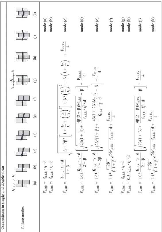
• a practical example on how the shear strength of a single fastener is computed according to the Johansen’s theory, as reported in the EuroCode 5 (Appendix B);
• some preliminary results related to experimental tests performed on bamboo specimens, in order to investigate the non-linear behaviour of sheathing-to-framing connections (Appendix C);
• an application of the proposed analytical procedure to the reference configuration wall used to validate the FE model (Appendix D).
2 | Timber Light-Frame buildings
Abstract
A code framework about timber structures, with references for the classifica-tions, marking of wood-based products and rules to design timber buildings, is here provided. An overview of the widespread construction systems is also given, with focus on the basic elements belonging to the one studied in this thesis.
Figure 2.1.The Vivenzio’s a-seismic
prototype (top[27]) and opus craticium wall,
Her-culaneum (bottom [27,
2.1 Code framework
The code framework has been often incomplete and wary about the use of timber for buildings. The first law that cited timber was the Royal Decree 18/04/1909, n. 193, which regards framed constructions and the Borbone a-seismic system known as Casa baraccata, the Engi-neer La Vega’s invention, based on an ancient wooden constructive tradition adopted in Calabria region (Fig. 2.1). The structural sys-tem recalls the characteristics of the Opus Craticium, a construction technique already described by Vitruvio and rediscovered during the excavation at Herculaneum on 1740. It is comprised of masonry re-inforced by means of a web of timber elements, and it was mostly adopted for the reconstruction after the strong earthquake that struck the Calabrian territory on 1783.
Law n.1684, 25/11/1962 permits only lumber constructions autho-rized preventively by the Civil Engineering office, whereas law n. 64 2/2/1974 cites timber structures imposing height limits “where con-struction systems other than masonry or with reinforced and standard pre-stressed concrete, steel or combined systems of the aforesaid materials, are used for buildings with four or more floors within and above ground, the suit-ability of such systems must be proven by a statement issued by the president of the board of public works on the advice of the same council”. The Min-isterial Decree 16/1/1996, says "The upright ribs and other parts making up the static organism of wooden buildings must be one-piece or connected in such a way that there is no weakening at the joints". Notably, this is in con-tradiction with the EuroCode 8[21]according to which "the dissipative zones must be localized in correspondence of the nodes and the connections, while an elastic behavior must be assumed for the wooden members".
Law n. 64 (2 -2-1974) FRAMEWORK LAWS Law n. 1086 (5-11-1971) NTC-05 O.P.C.M. 3431/2005 2005 NTC-08 2008 END 1996 CNR-DT-206 DM96 (NICOLE) Implementing decrees END
STRUCTURAL EUROCODES EN 1995:2004 A1:2009
Figure 2.2.Code framework until
2008(from[29]).
In Italy, the code framework has been modified on December 2011 through the Legislative Decree n. 201, 6/12/2011. At the art. 45, it states: “If materials or construction systems other than those governed by the technical regulations in force are used, their suitability must be proven by a declaration issued by the President of the Board of Public Works on the
26|Chapter 2
basis of the opinion of the same Council", thereby removing limitations of a regulatory nature for the construction of a multi-storey building in seismic area made entirely by wood. A proposal of national legisla-tion was developed by a special Commission at the Nalegisla-tional Research Council (CNR) that was named Nicole (Norme tecniche italiane per la progettazione, esecuzione e collaudo delle costruzioni di legno). It serves at preparing a text of Instructions (C.N.R. DT 206) as support for the application of Constructions Technical Standards[30]. A summary of legislative evolution is shown in Fig. 2.2.
The reference European codes for timber structures are:
1. UNI EN 338:2016[31], UNI EN 14081:2016[32](which classify strength classes for solid coniferous wood) and UNI EN 14080:2013[33](which classifies glued laminated timber). An example of marking is shown in Fig. 2.3.
Figure 2.3.CE marking for glued
laminated timber (left)
and solid timber (right). 1. EN 1995 - EuroCode 5 [20], which provides common rules for the
static design;
2. EN 1998 - EuroCode 8, chapter 8[21], which gives specific rules for seismic design of timber buildings.
EuroCode 8 provides definitions and methods to compute the seis-mic action as function of the elastic spectrum, the main elastic period of the structure, its regularity, seismic mass and ductility along with dissipative behavior. The verifications are performed in terms of re-sistance to seismic actions for the Ultimate Limit States (ULS) and of
maximum compatible inter-storey drift for Serviceability Limit States (SLS).
The reference Italian code for timber structures is the Construction Technical Code (NTC), Ministerial Decree 2008-01-14, chapter 4.4 and 7.7 for seismic design[30].
2.2 Timber classification
The commercial timber types are divided in two main groups, namely: i) softwood and ii) hardwood. These terms refer to the botanical origin of timber and do not reflect the actual softness or hardness of wood. Softwood are generally evergreen with needle-like leaves comprising single cells called tracheids, which fulfill the functions of conduction and support. The most diffused European softwood are, for example, spruce, larch, Scots pine and Douglas fir. Whitewood is sold generally for carcassing, inexpensive construction and painted material. The uses of redwood ranges from flooring to cladding, roof joists and pic-ture framing. Larch is generally sold for cladding, decking or marine applications while Cedar is adopted for construction and joinery. As reported in[34], the main characteristics of softwood are:
• quick growth rate (trees can be felled after 30 years) resulting in low-density timber with relatively low strength;
• generally poor durability, unless treated with preservatives;
• they are readily available and comparatively cheaper due to the speed of felling.
Conversely, hardwoods are not evergreen and often lose their leaves at the end of each growing season, and are generally broad-leaved trees (deciduos). Their cell structure is more complex than that of softwoods comprising thick-walled cells, called fibres, (which provide the structural support) and thin-walled cells called vessels (providing the medium for food conduction). The most diffused European hard-woods are oak, beech, ash, alder, birch, maple, poplar, willow.
As reported in[34], the main characteristics of hardwood are: • slower growing rate than softwoods, which generally results in a
timber of high density and strength that takes more time to mature (over 100 years in some instances);
• there is less dependence on preservatives for durability qualities; • they tend to be expensive in comparison with softwoods due to the
time taken to mature and the transportation costs (since they mostly grow in tropical zones).
28|Chapter 2
2.3 Construction systems
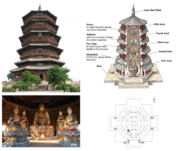
Timber has been the first and most important material used to build bearing structures, mainly for its lightness and easy assembly. Nowa-days, timber is also appreciated because of its aesthetic pleasure, sus-tainability and high strength-to-density ratio that ensures a reduction of the inertial forces under dynamic loads. The Sakyamuni Pagoda is an example of ancient structure made in timber. It was built on 1056with a total of 9 storeys whereas height and base diameter are equal to 67 m and 30 m, respectively (Fig. 2.4). According to historical chronicles, it withstood many destructive earthquakes.
Recent studies revealed that timber creates less pollution than steel or concrete. Moreover, wood-based materials have environmental ben-efit in terms of crandle-to-grave and the gate-to-grave/reincarnation when compared to masonry and concrete materials.
Figure 2.4.Sakyamuni Pagoda,
Fogong Temple, Ying
County, Shanxi, China 1056.
For ordinary buildings, two types of light-frame configurations are commonly used, namely: balloon and platform framing[35].
2.3.1 Balloon- and platform-frame construction systems
Figure 2.5.A typical balloon frame
construction (left); a typ-ical platform frame con-struction (right) (from
[36]).
The definition "balloon frame" was coined as form of contempt for such kind of construction system, which was considered unfit to with-stand significant load levels. The previous construction system - re-alized by heavy timber beams jointed using mortise-and-tenon - was replaced, thereby allowing the construction of buildings without the experience of craftsmanship, which was required at the beginning to build tight joints[36]. The new constructive system was comprised of thin, closely spaced vertical timber members, named studs (or chords, according to[13]), connected with horizontal framing members, called joists for floors (or struts according to[13]) and rafters for roofs (Fig. 2.5, left).
The connections between the lightweight members, starting from balloon frame, were made by means of simple nails and their instal-lation did not require large efforts anymore. The studs run the full height of the building, from the sill plate at the bottom to the top plate under the rafters. The intermediate floor joists, named ribband, are notched into the studs whereas fire-stops are provided at floor lines, thereby interrupting the continuous air space between the studs.
con-30|Chapter 2
tinuity required for the studs, since the limited availability of long and straight members increases the overall cost. On the other hand, the benefits provided by this type of construction system were associated to its stability. Since the floor joists are supported directly on the studs the cross-grain members, as such as the ribband and fire-stops, do not affect shrinkage and swelling of the frame.
)
b
(
)
a
(
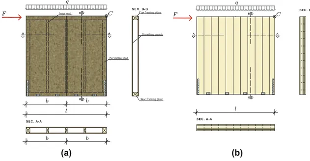
Figure 2.6.Type of walls employed
in platform framing
buildings: (a) Timber
Framed walls; (b) Cross Laminated Timber walls (from[37]).
Conversely, platform framing buildings have discontinuous fram-ing members (studs) connected usfram-ing plates supportfram-ing floor joists for each story, with a shear wall underneath. In this case, fire-stops are au-tomatically provided at each floor level (Fig. 2.5, right). Additionally, building structures with more than two stories is possible but differ-ent from the balloon frame because the length of studs imposes some limitations.
As pointed out by Porteous and Kermani [34], platform framed walls can be classified in the following two categories, namely: stud walls and racking walls.
The first category includes walls designed to carry vertical loads only with a sheathing panel that, if inserted, provides only an ad-ditional strength to the studs against in-plane and out-of-plane axial buckling. The walls belonging to the second category, instead, are de-signed to withstand in-plane lateral actions by means of the sheathing-to-framing connections.
The following types of walls are used in platform framed buildings (Fig. 2.6):
wood product realized by adhering and compressing wood layers called lamellas in perpendicular grain orientations to form a solid panel. Wood layers are glued together;
• Timber Framed walls (TF).
The dimensions of the frame are usually based on the size of the panel used to sheathed it on one or both sides, which is made by dif-ferent materials like OSB (Oriented Strand Board), plywood, gypsum, GLG (Glued Laminated Guadua) bamboo[38], fibreboard and so on.
The overall system can be subdivided into individual building com-ponents that could form either an overall system or be combined in the form of a composite system that have a relationship with the overall system.
Inspired by American experiences and successes, the first systems based on the platform frame appeared in Europe around 1930 and were designated as timber stud construction. It took place in a totally differ-ent manufacturing structure to that of the United States and in a way more suitable to European conditions and quality demands. It was particularly successful in Germany and Switzerland. The most im-portant difference between timber stud construction and timber-frame construction is the way the structure is braced.
Figure 2.7.Mortise-and-tenon joint
(from[36]).
The load-bearing framework of the second one is itself stiffened by the inclusion of inclined braces, whereas in timber stud construction the load-bearing framework is given by attaching solid timber sheath-ing to the outside or on both sides. Also the connections are different: in the timber stud construction, they are achieved via a direct contact between the timber members (compression), through nailing, lap and halving joints, in some cases using mortise-and-tenon joints (Fig. 2.7).
Modern timber stud construction, together with balloon- and platform-frame constructions, have been superseded in Europe by panel con-struction due to its far superior quality[39].
2.3.2 Panel construction system
The load-bearing structure in panel construction consists of load-bearing ribs of squared sections and a sheathing that stabilizes the ribs (Fig. 2.8). The individual vertical members carry the vertical load from roof and suspended floors, while sheathing panels resist to the horizontal forces and represent a bracing system for the component.
Figure 2.8.View of assembled
building without
ex-ternal sheathing (from
[39]).
The feature, and also the advantages, of this type of construction can be summarized as follows:
• design freedoms;
32|Chapter 2
• repetitive details;
• loadbearing ribs of slender, standardised sections; • building braced by sheathing;
• simple material procurement; • storey-by-storey assembly;
• connections achieved by direct contact and with mechanical fasten-ers;
• modular dimension 400-700 mm, preferably 625 mm; • construction clad both sides;
• short on-site time, different manufacturing depths possible.
2.4 Basic elements
For one- and two-storey buildings, timber sections measuring 60 ×
120mm are sufficient for the structural members. This could therefore be the basic element from which the main structure of the building is constructed. However, thermal insulation thicker than 120 mm is now often required in the external walls. The depth of the section must therefore either be increased from 120 to 160, 180, 200 mm. Alterna-tively, a second layer of insulation independent from the load-bearing construction must be provided.
As the addition of a second insulating layer also eliminates thermal bridges, this variation is the clear favorite. A hybrid solution, i.e. a deeper load-bearing construction plus a second layer of insulation on the outside, is also possible. In the case of multistorey panel construc-tion, larger sections will be needed for structural reasons anyway.
Figure 2.9.The parts of panel con-struction elements (from
[39]).
1Base plate
2Bottom and top plates, studs 3Assembly post
4Rib, joist
5Structural wall sheathing 6Structural floor sheathing
Figure 2.10.Exploded view
show-ing individual struc-tural elements (from
[39]).
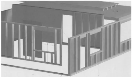
In panel construction, the main components are as follows (Figs. 2.9 and 2.10):
• Load-bearing ribs:
– structural timber (solid timber, compound sections), strength grade C24;
– species: spruce, fir;
– moisture content: 12% ± 2%.
To ensure good dimensional stability, the use of compound (solid) sections is recommended for panel construction.
• Stiffening wall and floor sheathing:
– 3-ply core plywood;
– OSB, MDF, particleboard; – gypsum fibreboard; – veneer plywood. • Thermal insulation: – mineral - fibreboards; – cellulose fibers; – wood fibreboards;
34|Chapter 2
2.4.1 Wall frame
The main feature of the wall assembly is that it includes several parallel and closely spaced members, joined at each end to a continuous cross member that runs perpendicular to the parallel members (Fig. 2.11). These cross members are the top and bottom plates.
Figure 2.11.Exploded view
show-ing the individual com-ponents of a wall (from
[39]).
The top plate of the wall can consist of one or two members, each of the same size of the studs. Doubling the top plate makes the whole structure stronger, allowing to place the floor joists or rafter anywhere on the top plate (Fig. 2.12).
Whether, instead, the top plate is comprised of just one element, the floor joists and rafters must be aligned with the underlying studs to transfer loads vertically till the foundation. The double top plate, in the latter case, does not have a beam-type role.
Figure 2.12.A detail of the top part
of a wall: (a) double top plate; (b) single top plate (from[36]).
The double plate is also useful to provide a structural continuity because floor and roof work as diaphragms in a wood frame build-ing. This produces tension as well as compression under wind and earthquake loads. The discontinuity at the joints, due to a single plate, instead, is not able to counteract tension forces. Building codes require a minimum of 24 inches (∼ 61 cm) lap at the joints between the two top plates (Fig. 2.13). For the same reason, the two top plates must be staggered at corners and junctions of the walls.
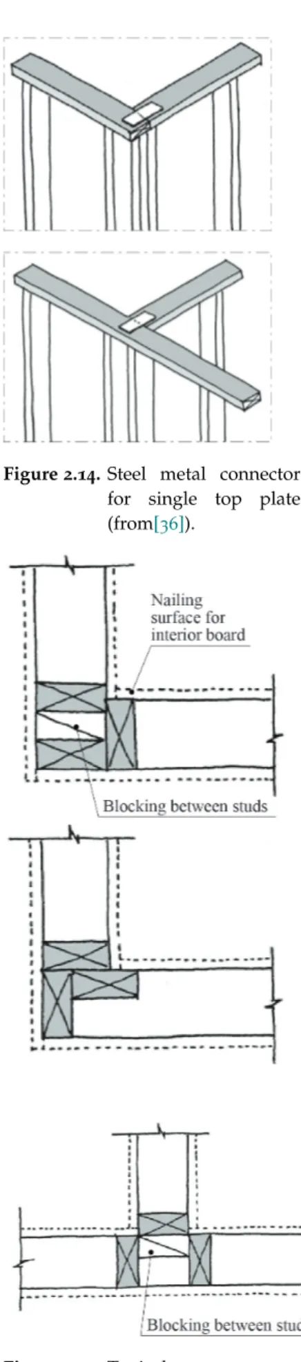
A sheet metal connector is needed at the joints when a single plate is used: this is why the single top plate is inconvenient (Fig. 2.14). Moreover, a typical arrangements of studs at corners is shown in Fig. 2.15.
A triple top plate is seldom used, if the distance between vertical studs is greater than 24 inches[36].
In the wall assembly, the bottom plate has a twofold designation, namely: sole plate or sill plate. In the first case, the single plate is not in contact with the foundation but is, for example, the bottom plate of the second floor. The sill plate is, instead, connected with the foundation and must either be a preservative-treated wood or a naturally decay-resistant wood specie.
2.4.2 Exterior walls: cross junctions
Figure 2.13.The junctions in
corre-spondence of top plate: (top) T-junction; (bot-tom) wall corner junc-tion (from[36]).
A shear wall, subjected to horizontal actions, has a resistance mostly influenced by the connections with the foundation and the other struc-tural elements1
. Therefore, the corner must be stronger than the field
1
The deeper study of this behavior is de-scribed in Section 5.6.
of the wall, requiring a minimum of three studs at the corner. More-over, the provision of three studs is needed to have ad adequate nailing surface to suitably fix the interior gypsum board and exterior sheath-ing panel.
2.4.3 Exterior walls: openings
Figure 2.14.Steel metal connector
for single top plate (from[36]).
steel angle or channel bottom plate
floor joists
noggins window header
top plate cripple studs
double studs at openings R hd hd hd hd hd hd hd R R R R R R R R R R: rafters hd: hold-downs
Figure 2.15.Typical arrangements
of studs at corners
(from[36]).
Openings within a shear wall require the use of the so-called jack studs on their both sides. They are partial-height studs that support the lintel beam, generally known as header (or lintel header). If the size of the opening is very large or the number of floors in the building exceeds two, the use of two or three jack studs may be needed.
A header is typically made of two or three 2-by lumber members2 ,
2
The 2-by notation is used to identify the widespread lumber thickness size used in constructions, equal to 2 in.
depending on the thickness of the wall. The members are face nailed to form a beam. If the wall is framed of 2 × 4 members, two 2-by lumber members are required, with a 12in.-thick filler (Fig. 2.16). The filler is usually a plywood or an OSB sheet. In a 2 × 6 wall, three 2-by lumber members are required with two filler sheets. For large openings, trussed headers or glulam headers are used.
2.4.4 Floor frame
The layout of a floor frame plan is comprised of joists that generally are laid in the direction of the shorter span and, when this is not possible, a glulam beam or a wall on the lower floor has to be inserted over long spans. Moreover, when there is a cantilevered floor, the joist must be bear on a support and securely connected at the far end to a wall or a beam. As for the joist framing around openings, also for cantilevered floor joists along opposite end have to be doubled. Further elements are inserted to prevent buckling of joists, called rims or bands joists that provide lateral restraints.
36|Chapter 2
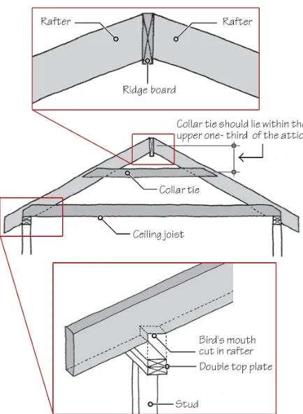
2.4.5 Roof frame
Generally, the roof is sloped and has gable, hip or shed shape. The slope is expressed as rise-to-run ratio, where run is kept constant and equal to 12. The greater the rise, the greater the roof slope, which allows to divide roofs in two types:
• low-slope roof with a rise-to-run ratio less than 3:12; • steep roof with a rise-to-run ratio greater than 3:12.
Figure 2.16.Headers made with
2-by lumber members: (top) 2 x 4 stud wall; (bottom) 2 x 6 stud wall (from[36]).
The roof frame could be comprises of trusses, shop-fabricated, or rafter-and-ceiling joist assemblies, site-fabricated. For the latter, the connection between two rafters is made through a continuous ridge board, which does not have structural function except to align the rafter ends in a straight line at the top and generally it is 2-by member element in LVL. Each rafter pair is tied together at the bottom to resist outward thrust created by the gravity loads on the roof. Then, to trans-mit load vertically at the supports, each rafter is cut to have a horizon-tal bearing on the supporting walls (Fig. 2.17) and the notch is known as bird’s mouth. Moreover, to prevent the separation of rafters due to uplift loads link to wind-load, collar ties are often located within the upper one-third of the attic.
Figure 2.17.The element that com-prise the roof frame:
(top) ridge board;
(middle) collar tie
(bottom) bird’s mouth (from[36]).
Abstract
A brief description of the main geometric and mechanical properties of the basic elements employed in timber light-frame shear walls is here provided. Further details and a deeper description of the sheathing-to-framing connec-tions is then reported in the next section, in order to introduce their main mechanical characteristics along with the mechanical models used in litera-ture and within the EuroCode 5. These characteristics will be used in the next sections to define the parametric FE model and to develop the analytical procedure aiming at predicting the global load-displacement curve of a timber light-frame shear wall.
3.1 Frame
A typical size of the framing elements cross-sections used in timber light-frame shear walls is about 38 mm × 89 mm and 38 mm × 140 mm for internal and external wall studs, respectively[7]. Also 80 mm × 160 mm, 120 mm × 160 mm, 120 mm × 200 mm, 140 mm × 160 mm and 160mm × 200 mm sizes are used in Italy and in Alpine area Countries
[26]. Further details about sizes of engineered wood products can be found in[34, §1.7].
The most common center-to-center spacing of vertical members is 12inches (:30.5 cm), 16 inches (:38 cm), 19.2 inches (:48.8 cm, sel-dom used) and 24 inches (:61 cm), according to the loads that act on the structure. The dimensions are also determined by the size of the sheathing panel adopted to brace, both one and two sides of the wall. The strength capability of timber is a function of several parameters, including species type, density, size of members, moisture content, du-ration of the applied load and various strength reducing characteristics like the presence of defects, knots, fissures etc. The design properties of timber are determined non-destructively, often with visual strength grading or by machine strength grading criteria. The interested reader can refer to[34, §1.5.1 and §1.5.2] for details about them. Timber are
40|Chapter 3 S tre ngt h cl as s Cha ra ct eri st ic st re ngt h prope rt ie s (N /m m 2) S ti ffne ss prope rt ie s (kN /m m 2) D ens it y (kg/ m 3) Be ndi n g T ens ion 0 T ens ion 90 Com pre ss ion 0 Com pre ss ion 90 S he ar M ea n m odul u s of el as ti ci ty 0 5% modul u s of el as ti ci ty 0 M ea n m odul u s of el as ti ci ty 90 M ea n she ar m odul us D ens it y M ea n de ns it y ( fm,k ) ( ft,0 ,k ) ( ft,90 ,k ) ( fc,0 ,k ) ( fc,90 ,k ) ( fv,k ) (E 0, m ea n ) (E 0 .05 ) (E 90 ,m ea n ) (G m ea n ) (ρ k ) (ρm ea n ) Soft woo da nd poplar spe cie s C1 4 14 8 0 .4 1 6 2. 0 1 .7 7 .0 4 .7 0.2 3 0.44 290 35 0 C1 6 1 6 10 0. 5 17 2. 2 1. 8 8. 0 5. 4 0.27 0.5 0 31 0 370 C1 8 18 1 1 0. 5 18 2. 2 2 .0 9. 0 6. 0 0.30 0.5 6 32 0 380 C2 0 2 0 1 2 0. 5 19 2. 3 2. 2 9. 5 6. 4 0.3 2 0.59 330 390 C2 2 2 2 1 3 0. 5 20 2. 4 2. 4 10. 0 6. 7 0.33 0.6 3 34 0 410 C2 4 2 4 1 4 0. 5 21 2. 5 2. 5 11. 0 7. 4 0.37 0.6 9 35 0 420 C2 7 2 7 1 6 0. 6 22 2. 6 2. 8 11. 5 7. 7 0.38 0.7 2 37 0 450 C3 0 3 0 1 8 0. 6 23 2. 7 3. 0 12. 0 8. 0 0.40 0.7 5 38 0 460 C3 5 3 5 2 1 0. 6 25 2. 8 3. 4 13. 0 8. 7 0.43 0.8 1 40 0 480 C4 0 4 0 2 4 0. 6 26 2. 9 3. 8 14. 0 9. 4 0.47 0.8 8 42 0 500 C4 5 4 5 2 7 0. 6 27 3. 1 3. 8 15. 0 10. 0 0.50 0.9 4 44 0 520 C5 0 5 0 3 0 0. 6 29 3. 2 3. 8 16. 0 10. 7 0.53 1.0 0 46 0 550 Hard woo ds peci es D 3 0 30 1 8 0. 6 23 8. 0 3. 0 10. 0 8. 0 0.6 4 0.60 53 0 640 D 3 5 35 2 1 0. 6 25 8. 4 3. 4 10. 0 8. 7 0.69 0.6 5 56 0 670 D 4 0 40 2 4 0. 6 26 8. 8 3. 8 11. 0 9. 4 0.75 0.7 0 59 0 700 D 5 0 50 3 0 0. 6 29 9. 7 4. 6 14. 0 11. 8 0.9 3 0.88 65 0 780 D 6 0 60 3 6 0. 6 32 10. 5 5. 3 17. 0 14. 3 1.13 1.0 6 70 0 840 D 7 0 70 4 2 0. 6 3 4 13.5 6. 0 20. 0 16. 8 1.3 3 1.25 90 0 1080 T en si o n o r co m p re ss io n pa ra ll el t o g ra in: ft,0 , fc,0 and E0 T en si o n o r co m p re ss io n pe rpe ndi cul ar t o g ra in: ft,90 , fc,90 and E90 Be ndi ng pa ra ll el to gra in: fm and E0 S he ar: fv and G S ubs cri pt s us ed are :0 , di re ct io n pa ra ll el to gra in ; 90 , di re ct ion pe rpe ndi cul ar to gra in ; m , be ndi ng ; t, te ns ion ; c, com pre ss ion; v, she ar ; k , cha ra ct eri st ic .
Table 3.1.Strength and stiffness
properties and density
values for structural
timber strength classes, (in accordance with Table 1, of EN 338:2003) (from
thus grouped into strength classes since from 1984[40], today collected in[31]and labelled with letter C and D according to their botanical ori-gin, softwood or hardwood respectively (ref. to Sec. 2.2 for details). The number of each class refers to its characteristic bending strength in N/mm2.
The characteristics properties (see Tab. 3.1) are defined as the popu-lation 5th-percentile values obtained from tests results with a duration of approximately 5 minutes at the equilibrium moisture content re-lating to a temperature of 20°C and a relative humidity of 65%. The interested reader can refer to[34, §1.5.3.1]for further details.
3.1.1 Headers for openings
Lumber is usually available in lengths of 8 ft, 10 ft, 12 ft (:244 cm, :305 cm, :366 cm), and so on, up to a maximum length of 26 ft (:792
cm). 94-1/8 in. 6 ft
Lintel header made of 2x12 lumber
7 ft 8-5/8 in. studs
Figure 3.1.The use of oversize
headers.
A special precut length that is commonly used for studs is 7 ft (:213 cm height) 858in. (:13 cm thick) (Fig. 3.1). The use of these studs saves on-site labor and gives a clear interior height (finished floor to ceiling) of 8 ft (:244 cm). The 8-ft clear height is common in multifamily dwellings, hotels, townhouses, and so on. If 2 × 12 headers are used with these studs, the opening height obtained is 6 ft (:183 cm height), which is the standard lintel height for residential doors and windows. Another commonly used special precut length of studs is 104 in. (:264 cm), which gives a floor-to-ceiling height of 9 ft (:274 cm). Note that 8-ft and 9-ft floor-to-ceiling heights conform to gypsum board panel sizes.
3.2 Sheathing panels
Wood panels can be used as either structural or non-structural ele-ments. The first case is related to the sheathing panels of walls, floors and roofs. The latter case deals with exterior siding and interior pan-eling.
In general, wood panels are divided into the following three classes: • Veneered panels, that consist of plywood panels;
• Nonveneered panels, consisting of Oriented StrandBoard (OSB) and particle board panels. The second type is mostly used for shelving and furniture making;
• Composite panels, consisting of two parallel face veneers with a non-veneer core. Their use in contemporary structural applications is limited.
42|Chapter 3
3.2.1 Plywood panels
Figure 3.2.Method of making
plywood veneers
com-monly in use (from
[36]).
This kind of panels is made by gluing wood veneers under heat and pressure.
Veneers are generally produced by a machine that holds a debarked log at two ends in a lathe and rotates the log against a stationary knife blade extending throughout the length of the log (Fig. 3.2). The ve-neer so obtained is subsequently cut to desired sizes, the defects in veneers, such as knot holes and splits, are cut away or repaired where necessary. The veneers are then dried and glued together so that the grain direction in each veneer is oriented at a right angle to the grain direction of the adjacent veneer.
The most commonly used plywood panel nominal size is 4 ft x 8 ft (:122 cm × :244 cm), with thickness varying from 1
4in. to 1 inch. (0.635 to 2.54 cm). Its actual dimension is:104.5 cm × :211 cm, which allows to install the panel all around for moisture expansion (Fig. 3.3).
Figure 3.3.Installation of plywood
panels: they must be
oriented with their long direction perpendicular to the supporting mem-bers and a gap of 3.2 mm must be left all around panels to accom-modate moisture expan-sion (from[36])
These panels are generally obtained from softwood, and are graded in five grades (from A - the highest - to D - the lowest) based on the defects size such as knots and splits[36]. Each panel has a different grade for the two different sides: it must be exposed on the side with the highest veneer grade. The main feature of the plywood panels used for sheathing is that, differently from those used for furnitures, they are unsanded. The core of the plywood is generally of rotary-sliced softwood veneers or particle board.
3.2.2 Oriented StrandBoard (OSB) panels
Figure 3.4.Surface appearance of
OSB panel (from[36]).
These panels are comprised of wood strands and the name is due to the alternate layers of strands, oriented at right angles to each other (Fig. 3.4). They are made by gluing the layers under heat and pressure, and have the same dimensions as plywood panels (4 ft x 8 ft =:122 cm ×:244 cm). The process used to arrange side-by-side the veneers of hardwood and softwood is called veneer matching.
This type of panel is preferred because of lower costs and high shear strength, as consequence of the lack of core voids (which is the most important factor in the racking resistance of a shear wall), especially along its long direction. Thus, it is used for floor, roof and wall sheath-ing in a typical wood frame buildsheath-ing.
There are some limitations in the use of OSB panels, namely: i) they are used only for structural applications, it is no possible neither to stain it, nor to paint it, differently from plywood; ii) they cannot be sanded smooth; iii) there are some problems with edge swelling if they remain wet for prolonged periods; iv) they cannot be treated with preservatives.
United Kingdom and are composed of wood strands, flakes or wafer sliced from small-diameter round timber logs. The strands are ori-ented in the long panel direction, with inner layers comprising ran-domly oriented wood strands. The strength is mainly linked to the multi-layered make-up and cross-orientation of the strands, which are bonded with an exterior-type adhesive (comprising 95% wood and 5% resin and wax) under heat and pressure.
The widespread use of OSB in place of plywood is due to its cost-effective, environmentally friendly and dimensionally stable panel, which may have various thicknesses (from 8 to 25 mm) and sizes (up to 2.4 wide×4.8 m long).
The code that provides information on the mechanic values is EN 12369-1:2001[34]complying with EN 300:1997[34]for use in designing structures to EC5:
• OSB/2 is a general purpose load-bearing panel for use in dry con-ditions only (service class 1);
• OSB/3 is a load-bearing structural panel for use in humid condi-tions (service classes 1 or 2);
• OSB/4 is a heavy-duty load-bearing structural panel for use in hu-mid conditions (service classes 1 and 2).
The grades intended for use in design and construction of load-bearing or stiffening buildings, like walls, flooring, roofing and I-beam, are grade OSB/3 and OSB/4. The minimum characteristics values for OSB are summarized in Tab. 3.2.
3.3 Connections for wood-based buildings
Traditionally, different types of interlocking joints were adopted to connect wood members. Nowdays, wood joints are built by simply nailing the members together or by nailing them through sheet metal connections as well as screws and bolts in some cases.
3.3.1 Nails
Figure 3.5.Types of nails in wood
frame constructions
commonly in use (from
[36]).
A nail is made of low or medium carbon steel wire that is heat treated to increase its stiffness. If a higher impact resistance is needed, then a higher carbon content is used. Whether no further treatment for cor-rosion is used, the nail is called brite nail. In exterior siding and decks, hot-dip galvanized are used, because cheaper than stainless steel nail. For increased holding power, nails are phosphate or vinyl coated. Vinyl-coated nails produce heat due to friction when the nail is driven, which increases the bond between the wood and the nail by melting
44|Chapter 3
the vinyl. They have a thinner shank and are easier to drive into wood and are, therefore, called sinker nails.
For framing connections common nails are generally used. A brief classification is shown in Fig. 3.5.
The (a) type is the common nail, its thick shank gives greater strength; (b) is called box nail and is used for attaching wood siding and shin-gles and its thin shank reduces wood splitting; (c) is the sinker nail, its tapered head sinks into wood and it is generally vinyl coated; (d) is called duplex nail and is used in scaffolding and concrete form work for temporary nailing; (e) is the casing nail, used for wood trim, win-dow frames, casing and decks; (f) is called finish nail and is used for finer carpentry and finishing; (g) is the ring shank nail, used for attach-ing floor sheathattach-ing and gypsum wallboard, with its rattach-ing shank gives greater holding power; (h) is called fluted shank nail and is used for attaching wood to masonry or concrete; this is the case when high car-bon steel is used to give greater impact resistance; (i) is the roofing nail, which is used for attaching roof shingles thanks to its large head[36]. The classification of nails is made using the so-called Penny system: the length of common nails in the United States is designated using the system originated in England, when 1 poundweight of 10d and 12d nails cost 10 pence 12 pence, respectively. A summary is reported below (Fig. 3.6 and Tab. 3.3).
Table 3.2.Strength, stiffness prop-erties and density val-ues for OSB boards com-plying with EN 300:1997 (based on EN 12369 -1:2001) (from[34]). Cha ra ct eri st ic M ea n m odul us Sec ti on D ens it y of ri gi di ty prope rt ie s Cha ra ct eri st ic st re ngt h (N /m m 2) (kg/ m 3) (N /m m 2) M ea n m odul u s of el as ti ci ty (N/m m 2) P la na r P ane l (rol li ng) P ane l P la na r Be ndi n g Com pr es si o n T ens io n sh ea r sh ea r she ar she ar Be n di ng T ens io n Com p re ss ion T hi ckne ss (mm) fm,0 ,k fm,90 ,k fc,0 ,k fc,90 ,k ft,0 ,k ft,90 ,k fv,k fr,k ρk Gv, mea n Gr, mea n Em ,0. mea n Em, 90 ,mea n Et, 0 ,mea n Et, 90 ,mea n Ec, 0, mea n Ec, 90 ,mea n O S B/ 2 : loa d -be ari n g b oa rd s fo r us e in dr y cond it ion s; O S B/ 3: loa d-be ari n g b oa rd s fo r us e in hum id condi ti ons > 6–1 0 1 8. 0 9. 0 15 .9 12 .9 9. 9 7. 2 6.8 1. 0 5 5 0 10 8 0 50 49 3 0 1 980 380 0 3 00 0 380 0 3 000 > 10 –1 8 16 .4 8. 2 1 5. 4 1 2. 7 9. 4 7. 0 6. 8 1.0 55 0 10 8 0 50 493 0 19 8 0 3 800 30 0 0 3 80 0 3000 > 18 –2 5 14 .8 7. 4 1 4. 8 1 2. 4 9 .0 6. 8 6.8 1. 0 5 5 0 10 8 0 50 49 3 0 1 980 38 0 0 3 00 0 380 0 3 000 O S B/ 4 : he av y-d ut y loa d-be ar in g b oa rd s fo r us e in h um id con di ti o ns > 6– 1 0 2 4. 5 13 .0 18 .1 14 .3 11 .9 8. 5 6.9 1. 1 5 5 0 10 9 0 60 67 8 0 2 680 43 0 0 3 20 0 430 0 3 200 > 10 –1 8 23 .0 12. 2 1 7. 6 1 4. 0 11. 4 8. 2 6 .9 1 .1 55 0 10 9 0 60 678 0 26 8 0 43 00 32 0 0 4 30 0 320 0 > 18 –2 5 21 .0 11. 4 1 7. 0 1 3. 7 1 0. 9 8. 8 6.9 1. 1 5 5 0 10 9 0 60 67 8 0 2 680 43 0 0 3 20 0 430 0 3 200 T h e 5% cha ra ct eri st ic v alu es fo r st if fne ss (i .e . Gk and Ek ) shoul d be ta k en as 0 .8 5 time s th e m ea n v al u es g iv en in thi s ta bl e. O the r prop ert ie s no t g iv en in thi s ta b le sha ll co m pl y w it h th e re qui re m ent s gi v en in E N 30 0 fo r th e gr ade s O S B/ 2, O S B 3 or O S B/ 4. P ane l shear: fv,k and G v,m ean T ens ion or c om pre ss ion pa ra ll el t o gra in : ft,0,k , fc,0,k and Et,0,me an , Ec,0,m ean T ens ion or c om pre ss ion pe rpe ndi cul ar t o grai n : ft,90,k , fc,90,k and Et,90,me an , Ec,90,m ean Be ndi ng para ll el to gr ai n: fm ,0,k and Em ,0,me an P la nar she ar: fr,k and G r,me an Be ndi ng perpe ndi cul ar to gr ai n: fm ,90,k and Em ,90,me an P la nar she ar: fr,k and G r,me an
46|Chapter 3
Figure 3.6.The nails sizes,
accord-ing to “Penny” system: (top) sizes bigger than 20d are included; (bot-tom) from 2d to 20d (from[36, 41])
![Table 3.2. Strength, stiffness prop- prop-erties and density val-ues for OSB boards com-plying with EN 300:1997 (based on EN 12369 -1 :2001) (from [34] )](https://thumb-eu.123doks.com/thumbv2/123dokorg/2894074.11449/45.918.361.802.114.1032/table-strength-stiffness-erties-density-boards-plying-based.webp)