Contents
1
EXECUTIVE SUMMARY ... 3
2
PREFACE ... 4
3
PWR 900 MW SEVERE ACCIDENT ANALYSIS ... 5
3.1
PWR PLANT DESCRIPTION ... 5
3.2
MELCOR CODE ... 5
3.3
MELCOR NODALIZATION DESCRIPTION ... 5
3.3.1
COR model ... 6
3.3.2
DCH model ... 6
3.3.3
Start of transient condition (steady state) ... 6
3.4
STATION BLACKOUT WITH TI-SGTR ... 9
3.4.1
Analysis of calculated data ... 10
3.5
UNMITIGATED LOSS OF FEED WATER ... 13
3.5.1
Analysis of calculated data ... 14
3.6
LARGE BREAK LOSS OF COOLING ACCIDENT WITHOUT ECCS FUNCTION 16
3.6.1
Analysis of calculated data ... 16
4
BWR FUKUSHIMA DAICHI UNIT I SEVERE ACCIDENT MODEL ... 19
4.1
PLANT DESCRIPTION ... 19
4.2
THE BWR MARK 1 CONTAINMENT DESCRIPTION ... 19
4.3
BOILING WATER REACTORS: SAFETY SYSTEMS ... 19
4.4
MELCOR 2.1 MODEL DEVELOPING ... 20
4.4.1
Thermal hydraulic model ... 20
4.4.2
Safety valves ... 20
4.4.3
Isolation Condenser model ... 22
4.4.4
CORE model ... 23
4.4.5
RN package ... 23
4.4.6
DCH ... 23
4.4.7
Cavities ... 23
4.5
REFERENCE ACCIDENT DESCRIPTION ... 24
5
SAFETY ANALYSES FOR ADVANCED PASSIVE REACTOR AND POSSIBLE
SEVERE ACCIDENT CODE ISSUES ... 27
6
SCALING AS ONE OF ORIGIN OF UNCERTAINTY IN CODE ANALYSES... 29
7
CONCLUSIONS ... 31
8
ABBREVIATIONS ... 32
1 EXECUTIVE SUMMARY
The Fukushima, Chernobyl and Three Mile Island accident determine that each country, that uses nuclear power plants in its national energy mix, is more focused on accident mitigation strategies of “severe accident” that could cause a source term of radioactive material to the enviroment. Several severe accident management analyses have been performed to analyze the accident progression, the core damage, the grace period and the fission product release demonstrating the management strategy adequacy.
Though the nuclear energy is not part of the Italian energy mix, among the twenty five NPPs in the Italian border areas, twenty are PWRs and five are BWR. Therefore the analyses of possible severe accident sequences are of interest for our national emergency preparedness strategy. Infact these analyses are the basis for the technical-scientific prediction of potential risk scenarios, the planning of first aid activity and possible prevention in order to minimize damage in the event of contamination of the Italian territory.
In the framework of the severe accident research activity developed by ENEA, the target of this work is to analyse, by using the MELCOR code obtained in the framework of the USNRC Research Program “Cooperative Severe Accident Research Program” (CSARP), transient scenarios that could take place in the nucler reactor at the Italian border.
In relation to the PWR reactor, the reference reactor, chosen for this analysis, is a generic PWR three loops design like of 900 MWe. Three different PWR accidents scenarios have been studied by using the MELCOR code:
- Unmitigated "Short term Station Blackout (SBO)" with a thermal induced Steam Generator Tube Rupture (SGTR),
- Unmitigated “Large Break Loss of Coolant Accident (LBLOCA)”; - Unmitigated “Loss of Feed water”;
Since they are assumed unmitigated and the actions of the operator are assumed to fail, they determine a BDBA. The analysis focus mainly in the characterization of the thermal hydraulic behaviour, the in-vessel phenomena, the core degradation and corium behaviour in the lower head. A first estimation of the source term is here also presented for the SBO scenario.
For the BWR, the preliminary Fukushima Unit 1 MELCOR nodalization, developed starting by the Peatch Bottom nodalization developed in the previous ADP ENEA-MSE last years, allowes to have a basis to analyse transients scenarios and compare the data with the calculated results of other codes and possible full scale plant transient data, if available.
Considering the interest of the international community for the advanced reactors, as the Small Modular Reactor (SMR), taking into account the central role of the thermal hydraulic for the prediction of a severe accident phenomenology, and considering the activity developed in the last years in Italy with the best estimate thermal hydraulic code TRACE in the framework of the USNRC Research Program “Code Applications and Maintenance Program (CAMP)”, possible activity of interest for the validation of severe accident code, against the SMR phenomena, are here presented. This activity is of strategic importance because it allows to "maintain" and "be protagonists" in the safety analyses issues of advanced reactors that could be installed in our Italian borders in the next short term.
The “scaling issue”, that determines uncertainty in the code calculated data, is here briefly presented and aspects of interest that should be investigated for the “severe accident” are underlined.
2 PREFACE
After the Fukushima accident the interest of each country, that uses nuclear power plants in its national energy mix, is more focused on the severe accident mitigation strategies. Several severe accident management analyses have been performed, to analyze the accident progression, the core damage, the grace period and the fission product release demonstrating the management strategy adequacy.
In general the nuclear reactors are designed to maintain the fuel damage and radioactive release within authorized limits during selected postulated accident (Design Basis Accident). A severe accident is a Beyond Design Basis Accident involving significant core degradation. Several computational tools can be used to analyze a severe accident transient. Considering the length and the several interacting phenomena, taking place during a severe accident, integral codes with a modular design are used and permit a fast transient simulation reproducing the different coupled phenomena. Example of severe accident codes are ASTEC, MAAP and MELCOR [1], [2] and [3]
Though the nuclear energy is not part of the Italian energy mix, among the twenty five NPPs in the Italian border areas, twenty are PWRs and five are BWR [4]. Therefore the analyses of possible severe accident sequences are of interest for our national emergency preparedness strategy. Since fifteen of the twenty PWR type reactors have a net electric power of about 900 MWe, the reference reactor considered for this analysis is a generic PWR three loops design like of 900 MWe.
The aim of this work is to analyse, by using the MELCOR code, three different accidents: a short term SBO (Station Blackout), a LBLOCA (Large-Break Loss Of Coolant Accident) and a LFW (Loss of Feed Water). To lead these three accidents to a BDBA, they will be unmitigated and the actions of the operator are assumed to fail. The analysis focuses mainly in the characterization of the thermal hydraulic behaviour, the in-vessel phenomena, the core degradation and corium behaviour in the lower head. A first estimation of the source term is here also presented for the SBO scenarios.
3 PWR 900 MW SEVERE ACCIDENT ANALYSIS 3.1 PWR PLANT DESCRIPTION
The reference reactor, chosen for this analysis, is a generic PWR three loops design like of 900 MWe [5] and [6]. The state of the art severe accident code, chosen for this analysis, is the MELCOR code [7]. A simplified preliminary, but exhaustive, MELCOR nodalization of the reference NPP, briefly described below, has been developed [8].
In general this kind of reactor is characterized by 3 loops; each loop is constituted by a single Hot Leg (HL) a single U tube SG, a loop seal, a single Cold Leg (CL) with a centrifugal pump. A Pressurizer (PRZ) is connected to one loop of the reactor through the surge line. The thermal power of the reactor is around 2700 MWth, the pressure of the primary system is around 15.5 MPa, the SG heat transfer surface is around 5000 m2 and the PRZ volume is around 40 m3. Safety Relief Valves (SRV) and PORV valves are installed in the PRZ and are connected to a Pressurizer Relief Tank (PRT). SRV valves are installed in each SG.
The system is located in a containment divided in several parts as the basement, the cavity, the SGs cubicle, the PRZ cubicle, the PRT cubicle, and the lower/upper dome part. All the structures of the containment (equipment’s, walls, floors and ceiling) during a transient, involving the containment, absorb/release energy and are the place where the fission product can deposit. Table 3-1 shows the generic value of a PWR 900 MWe like.
3.2 MELCOR CODE
MELCOR [7] is a fully integrate severe accident code able to simulate the thermal-hydraulic phenomena in steady and transient condition and the main severe accident phenomena characterizing the RPV, the reactor cavity, the containment, and the confinement buildings typical of LWR. The estimation of the source term is obtained by the MELCOR code as well. The code is based on the “control volume” approach. MELCOR can be used with the Symbolic Nuclear Analysis Package (SNAP) [11] in order to develop the nodalization and for the post processing data by using its animation model capabilities.
MELCOR has a modular structure and is based on packages. Each package simulates a different part of the transient phenomenology. In particular the CVH and FL packages simulate the mass and energy transfer between control volumes, the HS package simulate the thermal response of the heat structure and the COR evaluate the behavior of the fuel and core structures. It is to underline that the role of the CVH/FP packages that provide the boundary condition for other packages.
MELCOR is being developed at Sandia National Laboratories for the US Nuclear Regulatory Commission (NRC) [7] and [12].
3.3 MELCOR NODALIZATION DESCRIPTION
The MELCOR nodalization was designed to have a reasonable computational time and a realistic prediction of the phenomena involved during the transient assuring a reliable and accurate transient simulation.
The three different loops are modeled separately; each loop consists of the HL, SG primary side (U tubes), the loop seal, the pump and the CL. All the U tubes are modeled with two equivalent hydraulic
regions; one region represents the ascending U tubes side and the other represents the U tubes descending side. The PRZ and the related surge line are modeled as well. The vessel of the reactor is modeled with different hydraulic regions simulating the lower plenum, the core, the by-pass core, the upper plenum, the upper head and the downcomer. The upper head flow and the by-pass flow are modeled.
The U tubes ascending side is coupled with the riser of the correspondent secondary side by a heat structure. The descending part of the U tubes is coupled with the riser of the correspondent secondary side by another heat structure.
The SRV and the PORV valves are modeled. In particular three PRZ SRV trains are modeled separately.
The model consists in 55 control volumes, 96 junctions and 90 heat structures. Figure 3.1 and 3.2 shows the overall RCS thermal hydraulic MELCOR nodalization and the detailed loop 1 primary circuit thermal hydraulic MELCOR nodalization respectively.
3.3.1 COR model
The core is modeled by a single hydraulic region, CVH package, coupled with the correspondent MELCOR code model of the COR package. The Core, in the COR package, figure 3.3, is modeled with 17 axial regions and 6 radial regions. The lower plenum is modeled with 6 axial regions and the core with the remain 11 axial regions. All steel masses, Zircaloy masses and fuel masses are considered. In particular about 80 t of fuel are considered in the COR package.
3.3.2 DCH model
The elements data used for the decay heat calculation are reported in [18], in order to have specific data, related to a 900 MWe PWR reactor. The data used are the at equilibrium cycle.
3.3.3 Start of transient condition (steady state)
The initial conditions for all transients are the same. The principal parameters which characterize the steady state condition are reported in Table 3-2; the variation versus time of all parameters are negligeble after the stabilization period (8000 s).
Reactor thermal power, MWt 2775 Heat generated into the fuel, % 97.4 Primary circuit nominal pressure, MPa (a) 15.51 Total mass flow rate, kg/s 13734
Loop number 3
Pressure Vessel Height, m 13
Internal diameter, m 4
Mass, t 355
Thickness, mm 202
Core Linear power, W/cm 178.5
Inlet core temperature, °C 291.7 Core temperature difference, °C 36.9
Fuel assemblies Number 157
Rods per assembly 264
Rod external diameter, mm 9.5
Gap, mm 0.165 Clad thickness, mm 0.572 Clad material Zr. 4 Height, m 3.66 U235 Enrichment 3.20% UO2 mass , t 82.2
Control rods Number 48
Absorber material Ag-In-Cd
Pressurizer Volume, m3 40
Heaters number 50
Heaters max power, kW 1000
Primary pumps Number 3
Type Centrifugal single stage
Nominal Head, mH2O 84.7
Seal mass flow rate ( inlet, per pump), l/s 0.5
Seal mass flow rate ( outlet, per pump), l/s 0.2
Pipes Cold leg, internal diameter, mm 698.5
Cold leg, nominal thickness, mm 58.9 Hot leg, internal diameter, mm 736.6 Hot leg, nominal thickness, mm 62.2 Surge line, internal diameter, mm 284
Steam Generators Number 3
Type Vertical inverted U-tube
Heat transfer surface, m2 5110
Tubes material Inconel
Vapor pressure at full power, MPa (a) 6.6 Feedwater temperature, °C 226.7
Steam quality, % 99.75
Vapor mass flow rate, kg/s 516.6
Thermal power, MW 938
Figure 3.1: Overall thermal hydraulic MELCOR nodalization.
Figure 3.2: Detailed Loop 1 primary circuit thermal hydraulic MELCOR nodalization.
Figure 3.3: PWR core nodalization (COR package).
Parameter UM VALUE
Core Mass flow rate kg/s 13021 Bypass Mass flow rate kg/s 670
PRZ pressure MPa 15.41
Core inlet temperature °C 292 Core outlet temperature °C 329
PRZ level - 54%
Steam flow kg/s 1550
Steam generator feedwater temperature °C 120 Turbine inlet pressure MPa 6.6
Table 3-2: – Steady state parameters obtained by the MELCOR code.
3.4 STATION BLACKOUT WITH TI-SGTR
A Station Blackout (SBO) is a complete loss of alternating current electrical power to the essential and nonessential switchgear buses in the plant. Therefore, it involves the failure also of the onsite emergency AC power system. This analysis is focused on a Short-Term SBO with a thermal induced SGTR [9] and [10]. The transient will be unmitigated and the actions of the operator are assumed to fail to lead the accident to a BDBA.
The initial and limit conditions of the scenario implemented in MELCOR are:
At time = 0 s Loss of offsite power and failure of all the diesel generators;
The operator and automatic actions during the transient are:
Reactor scram;
Main Steam Isolation Valves (MSIVs) closure;
RCS and containment isolation;
Late RCP seals failure possibility;
Failure of the Turbine Driven Auxiliary Feed Water (TDAFW) pump;
The ECCS systems and the containment cooling system are inoperable;
Thermal induced SGTR.
The SGTR will be considered because when the core is overheated and the available cooling water is boiling off, steam and gas (hydrogen) circulate through the SG causing an increase of the thermal stress causing a SGTR. Since the hot fluid has the high temperature in the inlet plenum tube sheet this could be the position where the break could occur. This scenario is of interest because the SGTR causes a “containment by pass” release through the secondary system pressure relief valve.
3.4.1 Analysis of calculated data
After a MELCOR steady state analysis, in agreement with the full power operation values of the reference reactor, the SBO event takes place. In agreement with the expected reactor scenario, the SCRAM takes place, the MSIV is closed and the TD-AFW fails.
After the SCRAM a first primary pressure oscillation is predicted by the code followed by a pressure decrease mainly related to the SGs removal capability. The primary and secondary pressure evolutions are reported in Figure 3.4.
The SG SRVs begin their operation, considering the related pressure set points, at 372s after the SOT. Considering the SRV operation, a secondary pressure oscillation is predicted by the code. The SG dry out takes place at 3170s after the SOT, then the RCS pressure increases and the PRZ SRVs open at 4308s after the SOT; then the PRT failure takes place 5752s after the SOT. The core collapsed level falls below the top of active core 7100s after the SOT; the steam at the core exit is superheated 7150s after the SOT.
The natural circulation phenomena, taking place during a severe accident sequence, are important because the steam created in the core circulates along all the RCS transferring its energy and causing thermal stress and creep rupture in the RCS structures. At about 10800s there is a stuck open SG SRV event causing a SG secondary side depressurization near the atmospheric condition. The consequent differential pressure across the SG tubes with the contextual hot fluid flow, coming from the core, can causes the thermal induced SGTR.
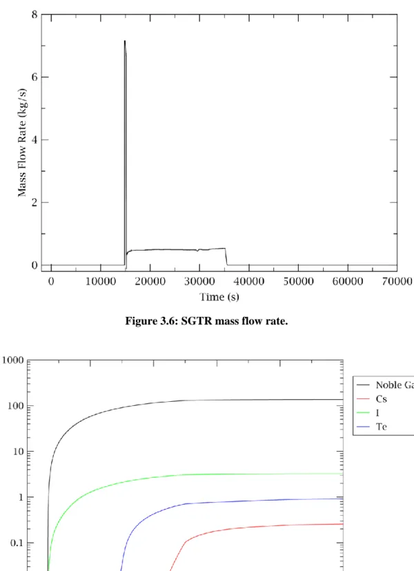
In particular the MELCOR code, by using the Larson-Miller model, as described in [9], predicts the induced thermal SGTR 14395 s after the SOT, while the induced thermal HL creep rupture is predicted 14907s after the SOT. The HL nozzle structure temperature profile is showed in the Figure 3.5. The SGTR mass flow rate is reported in the Figure 3.6.
The SGTR with the pump seal failure causes a first primary pressure decrease followed by a rapid pressure decrease when the induced thermal HL rupture takes place.
In order to analyzed the core degradation phases different parameters have been investigated: for example the onset of the fuel rod oxidation, the first control rod cladding failure, the first fuel rod cladding rupture, the peak fuel rod oxidation rate, the first fission product gas release, the fuel relocation in the lower plenum and the vessel failure. A view of the different core degradation phases is reported in [14]. In particular the vessel lower head failure takes place 33504s after the SOT. The hot debris in the core cavity ablates the concrete and non-condensable are created; this gas in conjunction with the steam created pressurize the containment. The total fission products distribution are the sum of the two source terms showed in Figure 3.7 (containment leaks) and in Figure 3.8 (SG SRVs via SGTR).
Figure 3.6: SGTR mass flow rate.
Figure 3.8: Products released from SG SRVs.
The results of the calculated data are in a qualitative agreement with the other similar analyses available in the technical/scientific literature. Different sensitivity analyses are in progress to assess the quantitative prediction of the code.
3.5 UNMITIGATED LOSS OF FEED WATER
The Loss of Feed Water (LFW) transient has received particular attention in the PWR safety analysis due to the potential for RCS over-pressurization. A LFW causes a decrease of capability of secondary system to remove the heat generated in the reactor core. Without an auxiliary feed water available, due to the SG gradual dry-out, the core residual thermal power would heat the water in the primary system to the point where the SRV from the PRZ would open, resulting in a substantial loss of water from the RCS. Considering that the transient is unmitigated, the LPI and HPI are hypothesized not available, and the only water entering into the core to compensate the loss of water coolant is that contained in the accumulators. The containment sprays are also hypothesized not available in this scenario.
At the state of art, the actual operator severe accident management actions would be stopping the main coolant pumps and the SEBIM valves are opened by the operator action to avoid the over-pressurization, consequently, the core degradation occurs at low pressure due to the primary circuit depressurization via SEBIM valves; in this transient no manual depressurization is considered and the only valves in operation are the PRZ and steam line SRVs.
The initial and limit conditions of the scenario implemented in MELCOR are:
HPI and LPI are unavailable;
At time = 0 s main feed water loss;
At time = 0 s auxiliary feed water unavailable;
At time = 0 s chemical and volume control system loss;
When the SG level =25% SCRAM;
At time = 1200 s main coolant pumps stop;
At time = 12000 s SEBIM valves open;
Isolation of accumulators when the pressure in the primary circuit is lower than 15bar.
3.5.1 Analysis of calculated data
After a MELCOR steady state analysis, in agreement with the full power operation values of the reference reactor, the LFW event takes place.
The loss of the main feed water, with the auxiliary feed water unavailable, lead to a dry-out in the SGs. When the level decreases to less than 25% in the SGs, the reactor scrams takes place and also the turbine is isolated. The secondary system loses gradually the capability to remove the heat and, after more than one hour (during this time the reactor is into a subcritical condition) the primary circuit reaches the maximum allowable pressure and the PRZ SRVs open. The pressure in both systems, as shown in Figure 3.9, is anchored between the on/off range of the respective SRVs for the first 11000 s.
Figure 3.9: Pressure transient during unmitigated LFW.
At 12000 s is hypothesized an operator action with the opening of SEBIM and the pressure in the primary circuit decreases.
So when the pressure is lower than 43 bar, the accumulators start to discharge water. In this simulation, the vessel fail is predicted at 23100 s, after the depressurization of the primary circuit, and a sequence of core degradation is reported in Figure 3.10.
FU CL PD MP1 MP2 Void SH FM PB MB1 MB2 SS NS OS HS H2O
Figure 3.10: Unmitigated LFW Core degradation sequence.
At the rupture of the vessel, the fission products are released, first in the containment, and after, through the small leakage1, part of those are released in the atmosphere.
1
The flow area of this leakage is practically zero for a containment pressure less than 3 barg, and after is considered proportional to the internal containment pressure further increment.
3.6 LARGE BREAK LOSS OF COOLING ACCIDENT WITHOUT ECCS FUNCTION
The LOCA (Loss Of Cooling Accident) is a rupture in the RCS causing the loss of the coolant. The phenomenology of the LOCA is correlated to the size of the break. In this analysis a large break in the CL of the loop containing the PRZ is simulated. In a PWR the unmitigated rupture of CL is a BDBA that could determine a severe accident.
The initial events and limit conditions of the scenario implemented in MELCOR nodalization are [13]:
At time = 0s Break of the CL connected to the PRZ;
Containment spray system is unavailable.
The operator and automatic actions during the transient are:
Reactor scram and turbine isolation;
Main Steam Isolation Valves (MSIVs) closure;
AFW actuation;
High and Low Pressure Injections systems (HPI & LPI) are available until the recirculation is required (first 5000 s);
Isolation of the accumulators when the pressure of the primary system is lower than 15 bar.
3.6.1 Analysis of calculated data
After a MELCOR steady state analysis, in agreement with the full power operation values of the reference reactor, the LBLOCA event takes place.
The large break of the primary circuit causes a large coolant release into the containment. The difference of pressure between the primary system and the containment induces a fast RCS depressurization and a pressure increase in the containment building, as showed in Figure 3.11. The main coolant pumps stops and SIS starts to inject water in the primary circuit with a mean mass flow rate of about 110 kg/s for the first’s 5000s of the transient (Figure 3.12). When the primary pressure reaches the value of 43 bar, the accumulators begin to discharge water in the RCS.
During the first phase of the blowdown, the break flow rate reaches 4700 kg/s (for initial seconds). For the period of the SIS working, the injected mass flow rate is similar to the break mass flow rate thus they keep constant the core water level. The containment pressure has a peak value. The flashing of the water discharged from the RCS determines steam production with consequent increases of the pressure in the containment building; after, the steam condensation, due to the heat sink, determines a pressure decrease. At the beginning, the containment pressure starts to increase because the heat sinks are unable to absorb all the energy released by the primary system. The pressure in the dome of the containment reaches a relative maximum of 3 bars at 115 s in the MELCOR simulation.
After the peak, the primary system pressure starts to slowly decrease until reaching the containment pressure. The RCS temperature is continuously decreasing also during the SIS discharging.
The RWST tank, at about 5000 s, is emptied, then the SIS stops and the discharge from the loop 1 CL break almost finish. After when the water level reaches the TAF, the pressure in the containment increases again. This transient leads the vessel to fail between the 3th and the 4th hour after the beginning of the accident. Figure 3.13 shows the unmitigated LBLOCA core degradation sequence.
Figure 3.11: Pressure trends during unmitigated LBLOCA transient.
FU CL PD MP1 MP2 Void SH FM PB MB1 MB2 SS NS OS HS H2O
4 BWR FUKUSHIMA DAICHI UNIT I SEVERE ACCIDENT MODEL 4.1 PLANT DESCRIPTION
Inside BWR vessel, a steam water mixture is produced when very pure water (reactor coolant) moves upward through the core absorbing heat. The major difference in the operation of a BWR from other nuclear systems is the steam void formation in the core. The steam-water mixture leaves the top of the core and enters the two stages of moisture separation, where water droplets are removed before the steam is allowed to enter the steam line. The steam line, in turn, directs the steam to the main turbine causing it to turn the turbine and the attached electrical generator. The unused steam is exhausted to the condenser where it is condensed into water. The resulting water is pumped out of the condenser with a series of pumps and back to the reactor vessel. The recirculation pumps and jet pumps allow the operator to vary coolant flow through the core and change reactor power.
4.2 THE BWR MARK 1 CONTAINMENT DESCRIPTION
The containment of a BWR is a pressure suppression containment. In general it is composed by a “wet well”, a “drywell” and a “vent system”.
In particular the Mark I containment includes a building (drywell), where the RPV and primary system are located. They are connected to the water-filled suppression chamber (wet well) that can be cooled over long periods of time in order to maintain lower pressures and temperatures, guaranteeing its integrity. If this cooling method is lost, the wet well can be vented under controlled conditions by operator action to the atmosphere, where the suppression water pool filters out radioactive material before the release of gases by the vent.
4.3 BOILING WATER REACTORS: SAFETY SYSTEMS
All BWRs have control rod drive systems that can be inserted to shut the reactor down. As a backup, there is also a standby liquid control system consisting of a neutron-absorbing water solution (borated) that can be injected to shut down the fission chain reaction.
In the event that the normal heat-removal pathway to the main turbine/condenser is lost, BWRs have, as the first backup, systems to provide core safety by either adding water to the RPV or by an alternate heat removal path, or by both.
BWR/3s have isolation condenser systems that both remove the decay heat by condensing the generated steam in the RPV through heat exchange with a water pool outside the drywell and return condensate to the reactor over a wide range of reactor pressures. No additional water is added, however, so if there are leaks in the primary pressure circuit, additional water is required from other sources.
BWR/4s and BWR/5s use an Reactor Core Isolation Cooling system (RCIC), which is a turbine-driven pump using reactor steam that can add water to the RPV over a wide range of reactor pressures. The RCIC system draws water from either a large pool inside the containment, the suppression pool, or from a tank located outside the containment, the condensate storage tank (CST). The RCIC system has the advantage that it can provide significantly more water than needed to make up for decay heat–generated steam, but it does not remove the heat. When the reactor becomes isolated from the main turbine/condenser, that heat is transported to the suppression pool via SRVs that open and close to maintain the primary system pressure within safety limits. There is sufficient heat capacity in the
suppression pool for many hours of decay heat storage before the heat must be removed from the containment using pumps and heat exchangers requiring electrical power. If this does not occur, the pressure and temperature in the containment will rise as time progresses.
If these first backup systems are not sufficient, then ECCSs are provided to both add water to the RPV and to remove decay heat either from the RPV or from the containment. With one exception, all these systems require alternating-current (AC) power that is supplied either by the NPP normal AC distribution system or by emergency diesel generators (EDGs) if the normal supply is lost. The exception is that as part of the ECCSs in BWR/3s and BWR/4s, there is a high-pressure coolant injection (HPCI) system that is a turbine-driven pump that uses reactor steam and that has about seven times the capacity of the RCIC system and can add water over a wide range of reactor pressures.
4.4 MELCOR 2.1 MODEL DEVELOPING
In order to develop the FUKUSHIMA unit 1 MELCOR Nodalization [17], following the SANDIA approach reported in the Fukushima Dai-ichi Accident Study (SAND2012-6173) [20], the nodalization has been based on the Peach Bottom reactor (different power but similar reactor). The references used to develop the BWR Peach Bottom nodalization are [21] and [22]. A complete decription of the Peach bottom BWR MELCOR input, developed by ENEA in the previous ADP ENEA-MSE last year, is reported in [17].
Starting from this model, the Fukushima Daichi Unit 1 input was built applying resonables scaling factor for each component.
4.4.1 Thermal hydraulic model
The MELCOR nodalization was designed to have a reasonable computational time and a realistic prediction of the phenomena involved during the transient assuring a reliable and accurate transient simulation.
The RPV MELCOR nodalization, made by using SNAP and shown in Figure 4.1, comprises the lower plenum, the core, the core bypass, the upper core plenum, the standpipes, the steam separator, the steam dome, the upper downcomer, the middle downcomer, the lower downcomer and the steam line. The 2 external recirculation loops are modelled separately, while the jet pumps are modeled with two equivalent jet pumps.
The number of the CVH is limited and this permits to obtain a fast running simulation, as required for this application.
4.4.2 Safety valves
The SRVs, located on a steam header attached to the main steam lines leaving the reactor vessel, vent steam from the reactor vessel into the wetwell. The SRVs have different opening and closing pressures; they open automatically when the opening pressure is reached. They also close automatically when the closing pressure in the vessel is reached. The SRVs are distributed into three bank of four, and three SRVs each, respectively. The two remaining spring safety valves have an automatic opening pressure of 8.555 MPa. Consequently, the spring safety valves will only open at high pressures after all the SRVs are already open. The spring safety valves close at a low pressure of 7.260 MPa.
The SRVs can also be opened manually at a pressure below the automatic set point. ADS actuation automatically opens five SRVs that discharge symmetrically into and around the torus below the suppression pool water level [20].
Figure 4.1: Fukushima 1 Unit thermal hydraulic nodalization. 4.4.2.1 Containment model
The primary and the secondary containment are modeled with the following nodalization, as represented in Figure 4.2.
The primary containment of the Mark-I design is modeled with of six separate regions: Drywell-In-pedestal; Drywell-Ex-pedestal; Drywell-Top; Drywell-Annulus; Vent pipes; Wetwell.
The secondary containment is modeled with nine separate regions: Torus room South 135 level North 135 level South 165 level Remain 165 level South 195 level Remain 195 level Refueling Bay
Turbine Building.
Figure 4.2: Fukushima 1 Unit containment nodalization.
The containment passive heat structures are modeled, in particular for the evaluation of the aerosol deposition.
4.4.3 Isolation Condenser model
The Unit 1 of Fukushima NPP have two ICs for removing the decay heat when the main isolation valve (MSIV) is closed and the main condenser is isolated. This passive system were originally designed to prevent over pressure in the RPV without activation of the SRV. When the pressure is higher than 7.13 MPa the IC goes in operation and continues more than 15 seconds, while the SRV activation pressure is about 7.27 MPa.
Considering the heat removal capacity of the two ICs after the reactor scram, in order to avoid thermal stress due to cold water inflow in the RPV, valve opening is adjusted (valve M3 REF [17]) in order to have a temperature change of the RPV less than 55 °C/hr (operator manual states) [17].
A first simple model was developed with CVH volumes and HS. A possible drawback of this model, very useful for a correct TH evaluation, as know, is a short time step required during the isolation condenser working, caused by condensation in the internal heat exchager shell. As visible in the next Figure, the presence of the condensation in the IC CHVs causes a time step with an order of magnitide 10-6 s, not compatible with a fast running calculation required by the scope of this application.
Figure 4.3: Visual output of the calculation.
For this reason, the model will be simplified with the aid of the ESF package, with the insertion of IC simple model. In this model the power removed by the IC depends only from a steam pressure, as described in [7].
4.4.4 CORE model
The core of the COR package is modeled with 23 axial levels and 6 radial rings. A core nodalization is shown in Figure 4.4. The Lower Plenum is modeled with 14 axial cells, another cell represent the core plate region and the remaining cells represent the active core region.
4.4.5 RN package
The RN package is activated and the most important parameters inserted are: Pool scrubbing data for the wetwell and the cavities;
Surfaces deposition and the intervolume transfer for the aerosol coefficients calculation.
4.4.6 DCH
The Decay Heat Package (DCH) data inserted are based on a standard ORIGEN calculation integrated in MELCOR, but next year it will be integrated with a specific evaluation, similar to what was done for the PWR.
4.4.7 Cavities
Two different cavities are nodalized. The first represents the in pedestal Drywell representing the first in contact with the corium when it exits from the vessel. The second represents the ex pedestal Drywell, which could receive the corium from the first cavity.
Figure 4.4: Fukushima 1 COR 3D and 2D (axial and radial) nodalization (COR package).
4.5 REFERENCE ACCIDENT DESCRIPTION
On March 11, 2011 at 14:46 (T0), an earthquake caused the loss of off-site power and the automatic reactor scram at Fukushima Daiichi Unit 1. After that, several events and actions have happened causing the well-known accidental sequence.
The accidental sequence can be schematically resumed following the 9 pictures of the Figure 4.5. As per picture a of Figure 4.5, after the earthquake, the off-site power was lost and all the control rods were inserted into the core. As expected, because of the loss of off-site AC power, loss of feedwater and condensate and main steam isolation valve closures occurred. Moreover, as expected, the emergency diesel generators started to cover the loss of off-site AC power; battery room and main control room were ok. Moreover, the IC automatically starts to operate at T0+6min causing a decrease in the reactor vessel pressure due to the heat removal through the ICs. The contemporary operation of the two ICs caused a higher cooldown rate that, for procedure limitations, cannot exceeded the 55°C/h. Because of this, operators cycled the ICs to maintain the correct pressure within the reactor vessel with an acceptable cooldown rate.
As per picture b of figure 4.5, at T0+41min, the first tsunami reached the NPP. The subsequent tsunamis caused flooding and damages at the intake structures. After that, the tsunami started to flood and submerge the emergency diesel generators and AC and DC distribution systems, causing the loss of AC and DC power. This also caused the loss of lights, indicators and controls in the main control room.
In the post tsunami condition (as per picture c of Figure 4.5), all AC and DC power systems were unavailable and the IC was the only system able to remove the decay heat from the reactor, without DC
power the system had to be operated locally. Moreover, after 8 hours of functioning, the IC required a source of makeup water for the condenser. As a result, Unit 1 had no injection or core cooling in service.
Operators tried to place the isolation condenser in service without success. As a result, there was no cooling method aligned to remove decay heat from the reactor (as per picture d of Figure 4.5).
Without any decay heat removal system in operation, the reactor pressure increased causing the primary steam vent, through the SRV, to the suppression pool (as per picture e of Figure 4.5). This caused a water level reduction and hence the uncovering of the core. Core degradation occurred causing release of reaction products (e.g. H2 from Zr oxidation) in the suppression pool (as per picture f of Figure 4.5). These reaction products reached also the drywell region. Because of the higher pressure in the reactor system the suppression pool was vented out (as per picture g of Figure 4.5). The venting was started too late and the atmosphere within the containment reached a too high hydrogen gas concentration. This caused at 15:36 on March 12, the explosion of the reactor building allowing radioactive materials to be released into the environment (as per picture h of Figure 4.5). Less than an hour after the explosion, radiation dose along the site boundary had reached 1.015 μSv/hr. Later, on March 12, the operators started to inject seawater into the reactor through the core spray system in order to cool the reactor; boron was then added to the water to control the reactor criticality.
This situation continued over the next several days as site personnel attempted to restore electrical power to the unit (as per picture i of Figure 4.5). Off-site power was restored to Unit 1 on March 20, nine days after the event.
5 SAFETY ANALYSES FOR ADVANCED PASSIVE REACTOR AND POSSIBLE SEVERE ACCIDENT CODE ISSUES
In the last 20 years, the international community, taking into account the operational experience of the nuclear reactors, starts the development of new advanced reactor designs, to satisfy the demands of the people to improve the safety of nuclear power plants and the demands of the utilities to improve the economic efficiency and reduce the capital costs [23], [24]. Design simplifications and increased design margins are included in the advanced Light Water Reactors (LWR) [24] and [25] .
In this framework, the project of some advanced reactors considers the use of emergency systems based entirely on natural circulation for the removal of the decay power in transient condition and in some reactors for the removal of core power during normal operating conditions [24] and [26]. For example, if the normal heat sink is not available, the decay heat can be removed by using a passive connection between the primary system and heat exchangers [24] and [25].
The AP600/1000 (Advanced Plant 600/1000 MWe) design, for example, includes a Passive Residual Heat Removal (PRHR) system consisting of a C-Tube type heat exchanger immersed in the In-containment Refueling Water Storage Tank (IRWST) and connected to one of the Hot Legs (HL) [24],[27], [28], [29].
A PRHR from the core via Steam Generators (SG) to the atmosphere, considered in the WWER-1000/V-392 design, consists of heat exchangers cooled by atmospheric air, while the PRHR via SGs, considered in the WWER-640/V-407 design, consists of heat exchangers immersed in emergency heat removal tanks installed outside the containment [24], [27], [29], [30].
In the AC-600 (Advanced Chinese PWR) the PRHR heat exchangers are cooled by atmospheric air [24], [27], [29], [31], [32], and in the System Integrated Modular Advanced Reactor (SMART) the PRHR heat exchangers are submerged in an in-containment refuelling water tank [24], [27], [29],[33].
The International Reactor Innovative and Secure (IRIS) design includes a passive Emergency Heat Removal System (EHRS) consisting of an heat exchanger immersed in the Refueling Water Storage Tank (RWST). The EHRS is connected to a separate SG feed and steam line and the RWST is installed outside the containment structure [24],[34], [35], [36].
In the advanced BWR designs the core water evaporates, removing the core decay heat, and condenses in a heat exchanger placed in a pool. Then the condensate comes back to the core [24], [37]. For example, the SWR-1000 (Siede Wasser Reaktor, 1000 MWe) design has emergency condensers immersed in a core flooding pool and connected to the core, while the ESBWR (Economic Simplified Boiling Water Reactor) design uses isolation condensers connected to the RPV and immersed in external pools [24], [25], [27].
The designs of some advanced reactors rely on natural circulation for the removing of the core power during normal operation. Examples of these reactors are the MASLWR (Multi Application Small Light Water Reactor), the ESBWR, the SMART and the Natural Circulation based PWR being developed in Argentina (CAREM) [24], [27], [38]. In particular the MASLWR [39] is a small modular integral PWR relying on natural circulation during both steady-state and transient operation.
In the last year the Fukushima accident has stimulated the debate on the role of nuclear energy in the sustainable energy mix to satisfy the energy demand increase in developing and developed countries. Though some states have decided to phase out the nuclear program, most of the states have maintained the idea to consider the nuclear energy as part of their future energy mix, ensuring security of energy supply; in fact, the nuclear reactors are capable to provide the base-load power in safe and carbon-free way, the majority of uranium resources are available in geographically diversified and politically stable OECD regions, as Australia and Canada, and the nuclear technology vendors are in general different from the uranium producers increasing the energy supply security of the nuclear choice [40].
Today the use of small modular integral reactors is one of the options for the use of the nuclear technology in a sustainable energy mix in developing and developed countries. These new designs are relatively portable and well suited for deployment on small electricity grids. Small Modular Reactors (SMR) provides parallel construction capabilities that reduce capital costs, construction times, and finance and costs. They are recognized to be able to reach larger electricity market around the world [40].
Considering the interest of the international community to this kind of designs, the analyses of the capability of the State of Art code to predict the phenomena characterizing these new designs is important in order to maintain updated the nuclear safety knowledge of the Italian Research Community and to be ready to perform safety analyses if these designes will be installed at the Italian border in the near short term.
Of particular interest is the coupled behavior of the primary system and containment with respective integral Pressurized Water Reactor designs (iPWRs); in fact while in the traditional reactor designs it is possible to study the containment and RCS physical behavior separately in the new advanced passive iPWRs it is necessary to consider the physical behavior of the containment coupled with the RCS behavior [23].
Considering the central role of the thermal hydraulic for the prediction of a severe accident phenomenology, and considering the activity developed in the last years in Italy with the best estimate thermal hydraulic code TRACE [40-63], possible activity of interest for the validation of severe accident code, against the SMR phenomena are [64] and [65]:
Heat transfer in helical coil SG with fluid in superheated condition.
Target:
Prediction of a stable SG superheated at the SG exit.
Natural circulation regimes at different primary core power levels.
Target:
o Prediction of the correct pressure drops at several different primary power levels and different primary mass flow rates;
o Prediction of the correct primary mass flow rates at different core power levels. Primary/containment coupling.
Target:
o Prediction of the RPV blowdown/refill behaviour;
o Prediction of the Containment/RPV coupled pressure behaviour and pressure distribution along the RPV, Containment and ADS lines;
o Prediction of the RPV and Containment level behaviour; o Prediction of the evaporation and condensation phenomena.
6 SCALING AS ONE OF ORIGIN OF UNCERTAINTY IN CODE ANALYSES
The Nuclear Power Plant is a complex system with a complex geometry (heat source, heat sink, several components, auxiliary systems, several pipes to connect the several and different component of the plant, etc…) characterized by multiple-component phenomena and two-phase thermal hydraulic phenomena. Two-phase fluid determines the presence of liquid and steam with a certain phase distribution depending on pressure and size of conduit, possible thermal and mechanical non equilibrium, phase change etc. It is to underline that two-phase thermal hydraulic phenomena are in general characterized by different scales a) Macro scale or system scale (Primary system; Secondary system; Containment system…); b) Component-scale, zone scale or phenomenon scale (Component-Scale: pump, separator; Zone (Component-Scale: upper plenum; Phenomenon scale: counter current flow limiting); c) Micro scale or local scale: volume around 1 mm3. As a complex system, several kinds of designs (current reactors and advanced reactors) can be considered. Each design is characterized by several involved phenomena and different weight of phenomena during selected transient. Then phenomena should be characterized and investigated for each design. In the development process of current and advanced nuclear reactors, the thermal hydraulic analysis of single and two-phase fluid in complex systems under steady state and transient conditions, is crucial for the understanding of the physical and operational phenomena typical of these designs. This analysis starts with developing an experimental data base, “assessment data base”, which characterizes the prototype system thermo hydraulic behaviours correctly. The use of experimental facilities is fundamental in order to characterize the thermal hydraulics of these phenomena and to develop an experimental database useful for the validation of the computational tools necessary for the operation, design and safety analysis of nuclear reactors. In general it is expensive to design a test facility to develop experimental data useful for the analyses of complex system, therefore reduced scaled test facilities are, in general, used to characterize them. Since the experimental data produced have to be applicable to the full-scale prototype, the geometrical characteristics of the facility and the initial and boundary conditions of the selected tests have to be correctly scaled. Since possible scaling distortions are present in the experimental facility design, the similitude of the main thermal hydraulic phenomena of interest has to be assured permitting their accurate experimental simulation [66-85].
In order to reproduce the behaviour of a prototype in a scaled model, it is necessary to thermal hydraulically characterize both the local and the integral phenomena. The test facility geometry and the initial and boundary conditions of the experiment should be correctly derived according to the scaling laws to avoid scaling distortions that could compromise the target phenomena identified through a Phenomena Identification and Ranking Table (PIRT). The Separate Effect Test Facilities (SETF) are used to characterize single phenomenon or combined phenomena bringing out the localized and isolated behaviour in a system component (e.g., downcomer, pressurizer, hot and cold leg). The purpose is to reproduce localized prototype behaviours with minimum scaling distortions. In general, it is desirable to have full/almost full scale, prototype/almost prototype fluid condition and well defined boundary condition and instrumentation dedicated to the characterization of selected phenomena. The Integral Test Facilities (ITF) are used to characterize the integrated system responses of a reactor region (e.g., RCS and containment), including the interaction between different phenomena and components. The data obtained from both SETs and ITFs can be used in model development/improvement and code assessment and validation. Different scaling approaches (time preserved/not preserved, full height/reduced height, full pressure/reduced pressure, etc.) and methods (Linear, Power/Volume, Ishii’s reduced height, H2TS, FSA etc.) have been developed in designing test facilities in the past decades. Together with the scaling analysis, the best estimate thermal hydraulic system code can be used in supporting the design of the experimental facility (ideal rig and boundary/initial conditions), in assessing the scale distortions, and in verifying the selected scaling method. The code has to be able to reproduce the qualitatively and quantitatively thermal hydraulic behavior of experimental test facility of different scale till full scale prototype condition. Since constitutive equation/ mathematical physical model are flow regime dependent, to develop and validate it need separate effect tests in different and several scales. Since the results of the
experimental data are related to the facility scale, constitutive equation/ mathematical physical model has to provide a realistic description of the phenomena /process with the correct scale feedback [66-91].
Since the closure laws in the system code are mainly based on scaled test data, the extrapolation of code results remains a challenging and open issue. Considering the previous points the application of the code results at a full scale prototype condition requires or a conservative approach or best estimate plus uncertainty application [87-90].
The objective of this research activity is to [64] and [65]:
Analyse the scaling properties of the experimental database developed in the last years for the extrapolation to the prototype and for the assessment of the code;
Give some insight about the scaling methods used in scaling-down experimental test facilities; Analyse the experimental facilities distortions and the consequent effects on the phenomena
simulation;
Analyse the extrapolation problems (scale-up) for ITF and SETF experimental database; Analyse the use of computational tool (best estimate code, lumped parameter code etc) as
extrapolation tool;
Analyse the scaling extrapolation methodology/procedures for the application of code as extrapolation tool and for safety analyses;
Analyse the capability of severe accident code and thermal hydraulic code to simulate transient at different scales (similar/counterpart test) and assess code scale-up capability; Understand how to assure uncertainty in the calculated results for prototype if no reference
experimental data are available or if the experimental data not cover the prototypical range. Analyses the influence of the scaling problem to correctly estimate uncertainty in the severe
accident analyses.
Within this regards the research activity presented at the Workshop on Nuclear Safety and Severe Accident (NUSSA-2014), Kashiwa, Chiba, Japan, September 3-5, 2014 titled “Scaling Rationale Design and Extrapolation Problem for ITF And SETF”[71] describes a short general view of the scaling issue providing some insights about the methods used in scaling of ITF and SETF.
The paper presented at the 16th International Topical Meeting on Nuclear Reactor Thermal Hydraulics (NURETH-16), Chicago, IL, USA, August 30-September 4, 2015 titled “Scaling Issues for the Experimental Characterization of Reactor Coolant System in Integral Test Facilities and Role of System Code as Extrapolation Tool”[92] provides a detailed analyses of the assessment database application through selected figures of merit based on previous counterpart test analyses. The issues and merits of the codes are therefore discussed and an “Assessment Database Diagram” is presented at the “International Scientific Community”. The target of the “Assessment database Diagram” is to link and analyse all the main components and methodology to develop scaled-down experimental data that can be used for the prototypical reactor characterization and for code validation.
7 CONCLUSIONS
After the Fukushima accident the interest of each country, that uses nuclear power plants in its national energy mix, is more focused on the severe accident mitigation strategies. Though the nuclear energy is not part of the Italian energy mix, among the twenty five NPPs in the Italian border areas, twenty are PWR and five are BWR. Therefore the analyses of possible severe accident sequences are of interest for our national emergency preparedness strategy.
One PWR 900 MWe like MELCOR nodalization and one Fukushima Unit 1 BWR like MELCOR nodalization have been developed in order to analyse unmitigated plant transient scenarios that could determine core degradation and source term to the enviroment.
Three different PWR accidents scenarios have been studied -short term SBO, LBLOCA and LFW-; since they are assumed unmitigated and the actions of the operator are assumed to fail, they determine a BDBA. The analysis focus mainly in the characterization of the thermal hydraulic behaviour, the in-vessel phenomena, the core degradation and corium behaviour in the lower head. A first estimation of the source term is here also presented for the SBO scenario. The results of the calculated data are in a qualitative agreement with the other similar analyses available in the technical/scientific literature. Different sensitivity analyses are in progress to characterize the quantitative prediction of the code. A detail analyses of the natural circulation phenomena taking place during a severe accident sequence [101], underlines that the steam created in the core circulates along all the RCS transferring its energy and causing thermal stress and possible creep rupture in the RCS structures. The thermal hydraulic configuration of the loop seal is one of the phenomenology that characterizes this natural circulation behaviour and the consequent thermal load distribution along the RCS structures.
For the BWR, the preliminary MELCOR nodalization obtained allowes to have a basis to analyse transients scenarios and compare the data with the calculated results of other codes and possible full scale plant transient data, if available.
The research activity, here also presented, related to the advanced reactors, that could be in operation in the near short term also in the Italian border, underlines the phenomenology that could be of interest to investigate for the validation of the computational tool used for the characterization of transient scenatios in DBA and BDBA.
The research activity about “scaling” underlines the importance of the “scaling issue” in the validation and application of the code and its influence in the uncertainty analyses of the calculated data. The main objects of this research activity are underlined in the document.
8 ABBREVIATIONS
AP600/1000 Advanced Plant 600/1000 MWe; ASTEC Accident Source Term Evaluation Code BDBA Beyond Design Basis Accident
CAMP Code Applications and Maintenance Program
CAREM Natural Circulation based PWR being developed in Argentina CL Cold Leg
CR Control Rod
CRGT Control Rod Guide Tube
CSARP Cooperative Severe Accident Research Program CVH Control Volume Hydrodinamics
DBA Design Basis Accident
ECCS Emergency Core Cooling System EHRS Emergency Heat Removal System
ESBWR Economic Simplified Boiling Water Reactor FL Flow Path
FSA Fractional Scaling Analysis H2TS Hierarchical Two-Tiered Scaling HL Hot Leg
HPI High Pressure Injection system HS Heat Structure
IC Isolation Condenser
IRIS International Reactor Innovative and Secure; IRWST In-containment Refueling Water Storage Tank ITF Integral Test Facility
LH Lower Head
LPI Low Pressure Injection system LWR Light Water Reactor
MAAP Modular Accident Analysis Program MSIV Main Steam Isolation Valves
MASLWR Multi-Application Small Light Water Reactor
MELCOR Methods for Estimation of Leakages and Consequences Of Releases NPP Nuclear Power Plant
NS Non-supporting Structure PORV Pilot-Operated Relief Valve
PRHR Passive Residual Heat Removal PRT Pressurized Relief Tank
PRZ Pressurizer
PWR Pressurized Water Reactor RCP Reactor Coolant Pump RCS Reactor Coolant System RCV Reactor Coolant Vessel RN RadioNuclide
SIS Safety Injection Systems SBO Station Blackout
SCRAM Safety Control Rod Axe Man
SEBIM Safety Valves of Pressure Compensator SETF Separate Effect Test Facility
SG Steam Generator
SGTR Steam Generator Tube Rupture
SMART System Integrated Modular Advanced Reactor SMR Small Modular Reactor
SNAP Symbolic Nuclear Analysis Package SOT Start Of the Transient
SRV Safety Relief Valve SS Supporting Structure SWR Siede Wasser Reaktor TAF Top of Active Fuel
TDAFW Turbine-Driven Auxiliary Feed-Water pump WWER Water Moderated, Water Cooled Energy Reactor USNRC US Nuclear Regulatory Commission
9 REFERENCES
[1] Safety of Nuclear Power Plants: Design, IAEA Safety Standards, Specific Safety Requirements, No. SSR-2/1SOARCA 1 2
[2] Severe Accident Management Programmes for Nuclear Power Plants, IAEA Safety Standards, Safety Guide No. NS-G-2.15Melcor Manual
[3] Research and development with regard to severe accidents in pressurised water reactors: Summary and outlook, Rapport IRSN-2007/83, Rapport CEA-2007/351
[4] IAEA PRIS 2014 Nuclear Power Reactors in the World, Reference Data Series No. 2 (Vienna: IAEA)
[5] ENEL Direzione delle Costruzioni DIR-PUN 1986 Progetto Unificato Nucleare - I Quaderni dell'Energia No. 12
[6] Lillington J N et al. 2001 Main Characteristics of Nuclear Power Plants in the European Union and Candidate Countries, EUR 20056
[7] Gauntt R O 2005 MELCOR Computer Code Manuals, Vol. 1: Primer and Users‟ Guide Sandia National Laboratories Albuquerque, NM 87185-0739, NUREG/CR-6119
[8] Lombardo, C., Caruso, G., Giannetti, F., and Vitale Di Maio D. 2013 Calcoli per la caratterizzazione dei vari impianti nucleari in condizioni di incidenti gravi. RdS/2013/064 [9] U.S.NRC 2013 State-of-the-Art Reactor Consequence Analyses Project Volume 2: Surry
Integrated Analysis NUREG/CR-7110, Vol. 2, Rev. 1
[10] U.S.NRC 2010 SCDAP/RELAP5 Thermal-Hydraulic Evaluations of the Potential for Containment Bypass During Extended Station Blackout Severe Accident Sequences in a Westinghouse Four-Loop PWR NUREG/CR-6995
[11] APT 2007 Symbolic Nuclear Analysis Package (SNAP) Users Manual. Applied Programming Technology, Inc. Bloomsburg, PA
[12] http://melcor.sandia.gov/about.html
[13] Vela-García, M., Sangiorgi M., Hermsmeyer, S., Analysis of LFW & LBLOCA scenarios for a PWR 900 MWe NPP using the integral computer codes ASTEC2.0 and MAAP4.0.8. The 7th European Review Meeting on Severe Accident Research (ERMSAR-2015) Marseille, France, 24-26 March 2015
[14] Giannetti, F., Mascari, F., Gramiccia, L., Naviglio, A., De Rosa, F., Station Blackout transient analysis for a PWR like design by using the MELCOR code. 32nd UIT Heat Transfer Conference, Pisa, Italy; 06/2014
[15] Carbajo, J. J., Severe Accident Source Term Characteristics for Selected Peach Bottom Sequerices Predicted by the MELCOR Code. NUREG/CR-5942
[16] State-of-the-Art Reactor Consequence Analyses Project Volume 1: Peach Bottom Integrated Analysis. NUREG/CR-7110, Vol. 1
[17] Parisi, C., Mascari, F., Balestra, P., Giannetti, F., Caruso, G., Fukushima Dai-ichi Unit 1 Accident Simulation by Best Estimate and Integral Codes & Accident Management Procedures Identification Focusing on BWR close to the Italian Borders. ADPFISS – LP1 – 044
[18] Rocchi, F., Guglielmelli, A., Sumini, M., Teodori, F., Calcoli di Inventari di Nocciolo: Affinamento della Metodologia ed Applicazione ai Reattori Frontalieri. ENEA technical report ADPFISS-LP1-007, September 2013
[19] General Electric, Mark I Containment Report March 19, 2011
[20] Gauntt, R. , Kalinich, D., Cardoni, J., Phillips, J., Goldmann, A., Pickering, S., Francis, M., Robb, K., Ott, L., Wang, D., Smith, C., Germain, S. St., Schwieder, D., Phelan, C., Fukushima Daiichi Accident Study, (Status as of April 2012), SANDIA REPORT SAND2012-6173 Unlimited Release. Printed July 2012
[21] Boiling Water Reactor Turbin Trip (TT) Benchmark, Volume I: Final Specifications, NEA/NSC/DOC(2001)1
[22] Severe Accident Source Term Characteristics for Selected Peach Bottom Sequences Predicted by the MELCOR Code, NUREG/CR-5942
[23] D‟Auria, F.; Modro, M.; Oriolo, F.; Tasaka, K. (1993). Relevant Thermal Hydraulic Aspects of New Generation LWRs. Nuclear Engineering and Design 145, 241-259 (1993)
[24] Mascari, F., Vella, G., Woods, B.G., Welter K., D‟Auria, F., Analysis of Primary/Containment Coupling Phenomena Characterizing the MASLWR Design During a SBLOCA Scenario, Nuclear Power Plants, Intech, 2012
[25] Aksan, N. (2005). Application of Natural Circulation Systems: Advantage and Challenges II, In: IAEA TECDOD-1474, Natural Circulation in Water Cooled Nuclear Power Plants, IAEA, pp.101-114, ISBN 92–0–110605–X, Vienna, Austria, 2005
[26] IAEA-TECDOC-1624. (2009). Passive Safety Systems And Natural Circulation In Water Cooled Nuclear Power Plants. IAEA, ISBN 978–92–0–111309–2, Vienna, Austria, November 2009
[27] IAEA-TECDOC-1391. (2004). Status of Advanced Light Water Reactor Designs 2004. IAEA, ISBN 92–0–104804–1, Vienna, Austria, May 2004
[28] Reyes, J.N. Jr, (2005), AP 600 and AP 1000 Passive Safety System Design and Testing in APEX, In: IAEA TECDOD-1474, Natural Circulation in Water Cooled Nuclear Power Plants, IAEA, pp.357-381, ISBN 92–0–110605–X, Vienna, Austria, November 2005
[29] Gou, J., Qiu, S.; Su, G., Jia D., (2009), Thermal Hydraulic Analysis of a Passive Residual Heat Removal System for an Integral Pressurized Water Reactor. Hindawi Publishing Corporation, Science and Technology of Nuclear Installations, Volume 2009, Article ID 473795, 12 pages, doi: 10.1155/2009/473795
[30] Kurakov, Y.A., Dragunov, Y. G., Podshibiakin, A. K., Fil, N. S., Logvinov, S. A., Sitnik, Y. K., Berkovich, V.M., Taranov, G. S., (2002), Development and Validation of Natural Circulation Based Systems for new WWER Designs, In: IAEA-TECDOC-1281, IAEA, pp.83-96, ISSN 1011–4289, Vienna, Austria, April 2002
[31] IAEA-TECDOC-1281. (2002). Natural Circulation Data and Methods for Advanced Water Cooled Nuclear Power Plant Designs. IAEA, ISSN 1011–4289, Vienna, Austria, April 2002 [32] Zejun, X., Wenbin, Z., Hua, Z., Bingde, C., Guifang, Z., Dounan, J., (2003), Experimental
Research Progress on Passive Safety Systems of Chinese Advanced PWR. Nuclear Engineering and Design 225 (2003) 305–313
[33] Lee, K. Y., Kim M. H. (2008). Experimental and Empirical study of Steam Condensation Heat Transfer with a Noncondensable Gas in a Small-Diameter Vertical Tube. Nuclear Engineering and Design 238 (2008) 207-216
[34] Carelli, M. D., Conway, L. E., Oriani, L., Petrovi´c, B., Lombardi, C. V., Ricotti, M. E., Barroso, A. C. O., Collado, J. M., Cinotti, L., Todreas, N. E., Grgi´c, D., Moraes, M. M., Boroughs, R.D., Ninokata, H., Ingersoll, D.T., Oriolo F., (2004), The Design And Safety
![Table 3-1: Generic PWR 900 MWe like data [8].](https://thumb-eu.123doks.com/thumbv2/123dokorg/5611108.68156/7.892.98.813.148.1082/table-generic-pwr-mwe-like-data.webp)