© 2018. Manuela Neri, Michele Brognoli, Davide Luscietti & Mariagrazia Pilotelli. This is a research/review paper, distributed under the terms of the Creative Commons Attribution-Noncommercial 3.0 Unported License http://creativecommons. org/licenses/by-nc/3.0/), permitting all non commercial use, distribution, and reproduction in any medium, provided the original work is properly cited.
Global Journal of Researches in Engineering:
JGeneral Engineering
Volume 18 Issue 1 Version 1.0 Year 2018
Type: Double Blind Peer Reviewed International Research Journal Publisher: Global Journals
Online ISSN: 2249-4596 & Print ISSN: 0975-5861
Interplay of Casting and CFD Software for Improved Accuracy
of the Simulation
By Manuela Neri, Michele Brognoli, Davide Luscietti
& Mariagrazia Pilotelli
Keywords:
numerical simulations, experimental results, casting.
GJRE- J Classification:
FOR Code: 091599
InterplayofCastingandCFDSoftwareforImprovedAccuracyoftheSimulation
Strictly as per the compliance and regulations of:
University of Brescia
Abstract-
The advantages of using two simulation codes in casting simulations have been
investigated: a fnite element code designed to simulate casting pro-cesses, and a fnite volume
CFD code designed to simulate thermal and uid-dynamic boundary conditions. The
temperature-time curve at an important injection point of a mould system has been measured: in this point,
the agreement between numerical and experimental results is very sensitive to the specific
boundary conditions that are assumed in the casting simulation. It has been demonstrate that
the agreement is good if instead the choice of boundary condition parameters are chosen and
tuned to experimental data with the help of a CFD code.
Interplay of Casting and CFD Software for
Improved Accuracy of the Simulation
Manuela Neri α, Michele Brognoli σ, Davide Luscietti ρ & Mariagrazia Pilotelli Ѡ
Keywords: numerical simulations, experimental results, casting.
I.
I
ntroductionastingprocesses can be divided into flling of the mold, solidification,and cooling, and they can be monitored by means of numerical simulations. There are several steps involved in the development of a casting simulation [1], of which the main important are: comprehension of the system/process, choice of a program (or writing of a code) to simulate the process, shape of the mold and definition of the materials properties, definition of the meshelement, application of the boundary conditions and interface conditions,run of the program, analysis of the results. In the majority of cases, to simulate a process, it is not possible to reproduce the system completely;rather,it is necessary to make simplifications of the system/process under investigation so as to include the relevant elements only [2, 3, 4]. The aim ofthis simplification is the reduction of the numerical model size and to perform less time-consuming numerical simulations. To be sure that the process hasbeen simulated properly, numerical results should be verified by means ofexperimental tests.
A review of experimental techniques for validating numerical solutions of flow configuration is presented in [5]: it has been stated that the validation of numerical model should be attended by the quantification of the uncertainty of the results obtained experimentally.
There are several available numerical techniques to perform numerical simulations [6-11],
among which the finite element method (FEM), the finite element difference (FDM) and the finite volume method (FVM). The difference among these techniques is related to the position where the variablevalue is stored: in the FEM and FDM methods it is stored at the element nodes, while in the FVM it is stored in the center of the volume. In the finite element method the domain is divided into hexahedral cells; in the FVMthe domain is divided into more volumes, and for each volume the governing equations are solved. In the finite FEM, discretization is based upon a piecewise representation of the solution regarding specified basis functions; the computational domain is divided up into finite elements, and the computedvalue in each element is constructed from the basis functions.
C
© 2018 Global Journals G lobal J our nal of Researches in Engineering ( ) V olume XVIII Is sue I V ers ion I 37 Year 2018 JTheoretically, by performing numerical simulations with different codes on the same model should lead to consistent results, but some codes are designed for a specific purpose and they may include different resolving models for simulating a phenomenon. For example, some codes are designed for casting simulations specifically, while others are dedicated to thermal-fluid-dynamic simulations; also the discretization of the domain and the way of solving the governing equation may affect the output of numerical simulations. To simulate casting process, FEM and FDM are usually used. Another parameter that influences simulation results is the grid: a regular and small grid allows to solve thermal-fluid-dynamic equations correctly, especially in the boundary layer.
The comparison of codes was performed in several fields. For example, codes accuracy was compared for jewelry casting [12]: the fluid flow inside a cavity was monitored in simulations performed with Magma, PROCAST, and FLOW-3D. Marshall [13] made a benchmarking of codes for simulating casting processes and it was stated that PROCAST is the best code among the ones analyzed. Experimental data was compared with results obtained by means of the CFD code Fluent [14].
Abstract- The advantages of using two simulation codes in casting simulations have been investigated: a finite element code designed to simulate casting pro-cesses, and a finite volume CFD code designed to simulate thermal and fluid-dynamic boundary conditions. The temperature-time curve at an important injection point of a mould system has been measured: in this point, the agreement between numerical and experimental results is very sensitive to the specific boundary conditions that are assumed in the casting simulation. It has been demonstrate that the agreement is good if instead the choice of boundary condition parameters are chosen and tuned to experimental data with the help of a CFD code.
Authorα:University of Brescia, via Branze 38, Brescia, Italy, via Branze 38, Brescia, Italy. e-mail: [email protected]
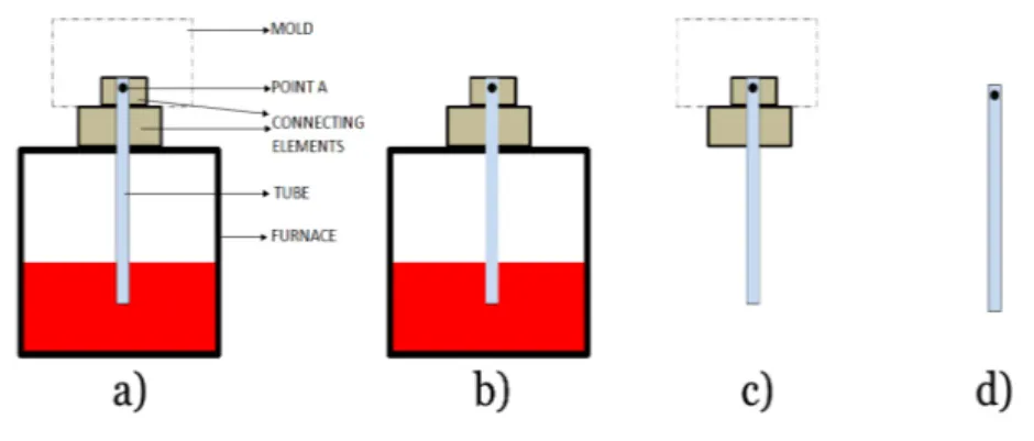
Figure 1:System under investigation: a) real case, b) system considered in the prelimi-nary simulations, c) system considered in the final simulations, d) standard configuration.
The temperature at point A is analyzed.
In this paper, the accuracy of two codes to predict the temperature in an alloy is investigated: one of them is a finite element code designed for casting simulations specifically, and the other is a CFD code. The studyhas requested the identification of parameters necessary for a true and fair view of a casting process simulation. The search for the most appropriate boundary conditions has led to the comparison of the two codes, and thishas highlighted how it is possible to take advantage of two or more codes designed for different purposes to improve casting simulations.
II.
C
ase ofS
tudy:A
nalysis of A
C
astingP
rocessThe process has been also simulated by considering the elements shown in Figure 1 c), that in
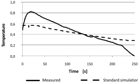
the following is denoted as standard configuration. A certain discrepancy has been detected between the process simulated withthe casting code using standard boundary conditions and measured temperature, as shown in Figure 2. Standard boundary condition consisted in an adiabatic condition on the external surface of the pipe, and a convectiveheat transfer and a related temperature on the connecting elements. The temperature at the entrance of the pipe was set equal to the temperature measured experimentally at point A; in this way, the passage of the alloy from the oven to the mold was not taken into consideration. The output ofthe numerical simulations was suffciently consistent with the realty except for the temperature of the alloy during the process at point A of Figure 1 a), with consequence from a metallurgical point of view: in the simulations,the final product presented a greater pasty zone near point A than the real product. In Figure 2, the temperature estimated by the numerical model is compared with temperatures measured experimentally: it is shown that at point A, despite at the beginning of the process the temperature of the alloy is lower than that measured in the oven, the final temperature is higher than that measured.
III.
M
ethod andR
esultsThe study has investigated the causes of the difference in temperature between estimated and measured temperatures in a casting process: it has consisted in numerical simulations executed with a finite element casting code(FE) and a CFD finite volume (FV)
© 2018 Global Journals © 2018 Global Journ G lobal J our nal of Researches in Engineering ( ) V olume XVIII Is sue I V ers ion I 38 Year 2018 J
Interplay of Casting and CFD Software for Improved Accuracy of the Simulation
code, and experimental tests have been performed to validate the numerical results.
As the causes of the difference between measured and simulated temperature were not known, the analysis has been quite articulated as sketched in In this paper, a particular casting process is
analyzed; the final product on which our experimental data is taken is not specified for reasons of trade secrecy, but this does not undermine the purpose of the study. The study has been prompted by a factory that produces objects using low pressure casting processes.
The process takes place in the system shown in Figure 1 a), that consists of an oven connected to a mold by means of a pipe; the pipe passes through the upper wall of the oven and other elements (called connecting elements in the following) whose function is to insulate and to hold it. The time duration of the process is non-dimensional. The process consists in the pressurization of the oven to 0.25 times the total time duration of the process, resulting in the consequent owing of the alloy in the mold. Then, the pressurization ceases and the cooling phase continues for 0.86 times the total duration of the process. It can be considered that after 0.04 times the total duration of the process the mold is filled of the alloy.
Figure 3. Given that it was not sure that the standard boundary conditions were correct, the first step of the study consisted in the investigation of theircorrectness.
Figure 2:Temperature estimated with the casting code using standard boundary conditions and experimental measurements at point A of Figure 1 a).
To make measured and estimated temperatures matching, specific boundaryconditions to be set in the casting code have been researched: they havebeen checked by performing a simulation with the numerical model shown in Figure 1 d) that includes the mold.
In the following, each step is deepened. Given that the temperature of the alloy in the process is a secret trade, unless otherwise noted, the temperatures are nondimensional concerning the temperature of the aluminum in the oven. To give an idea of the temperatures involved, the range of temperature in the graphs (from 0 to 1) is in the order of 1000C.
a) Measurement of the alloy temperature in the pipe
© 2018 Global Journals G lobal J our nal of Researches in Engineering ( ) V olume XVIII Is sue I V ers ion I 39 Year 2018 J
Interplay of Casting and CFD Software for Improved Accuracy of the Simulation
As it has not been possible to measure physical quantities in the oven, it has been necessary to simulate the entire system to determine the boundary conditions indirectly. To do this, a CFD code specifically designed for thermal fluid-dynamic computing has been used to perform numerical simulations on the configuration
shown in Figure 1 b). Boundary conditions so obtained have been set in the model shown in Figure 1 c): the model represents the pipe and the connecting elements, and numerical simulations have been performed with both the casting and the CFD codes. As only the temperature estimated with the CFD code has matched with measured data, the influence of the grid and the interface conditions has been investigated.
In Figure 2 the temperatures are nondimensional with respect to the temperature of the alloy in the oven: as the temperatures are lower than 1, the temperature at point A is lower than the temperature of the alloy in the oven. On an initial analysis, it has been inferred that the alloy undergoes a cooling process when it flows in the pipe; another hypothesis has considered that the thermocouple performs a distorted measurement. 0,4 0,6 0,8 1,0 Te m pe ra tu re 0,0 0,2 Time [s] 0 50 100 150 200 250
Interplay of Casting and CFD Software for Improved Accuracy of the Simulation
Numerical simulation with the CFD
(configuration in Figure 1 b) Heat flux on the external surface of the tube Identification of the buondary condition Convective heat trasnfer coefficient and related temperature on the external surface of Influence of Numerical simulations with the casting code. the tube Influence of the dimension of the grid and the interface
conditions Numerical simulations
with the CFD code (configuration in Figure 1c) Comparison between (configuration in Figure 1 c) estimated and measured temperatures Measurement of the temperature at point A and assesment of the influence of the sensor on the measured Identification of the boundary condition for
the casting code on the measured temperature Simulation performed with the casting code (configuration Figure 1 d)
Figure 3:Scheme of the study with the finite element casting code is identified, with the finite volume CFD code is identified. © 2018 Global Journals © 2018 Global Journ G lobal J our nal of Researches in Engineering ( ) V olume XVIII Is sue I V ers ion I 40 Year 2018 J
Firstly, it was investigated whether the difference between the maximum temperature measured at point A and the temperature of the alloy is due to the time response of the sensor.
The response of a thermocouple sensor depends on its properties and the environment in which it is immersed; however, no sensor responds instantly to a change in its environment. The temperature at point A
Interplay of Casting and CFD Software for Improved Accuracy of the Simulation
of Figure 1 a) has been measured using a thermocouple
Figure 4:Temperature trend measured by a thermocouple immersed in the alloy for estimating the time response of the sensor. The time axis is non dimensional with respect to the total time duration of the process. τ of type K, immersed in the duct so as its tip has reached
the center of the ceramic pipe. To protect the thermocouple from the high temperature, it has been
encased in a covering made of INCONEL 600 [16] of 9 mm in diameter that could have caused a retard in the measurement.
To quantify the thermocouple time response , a test has been performed: a thermocouple similar to that used to measure the temperature at point A has been immersed in the alloy at temperature and the variation in temperature detected by the thermocouple has been monitored. Figure 4 shows the temperature detected by the thermocouple which has been used to compute the time constant of the thermocouple following the approach proposed by [15]. The temperature of the alloy at a given time instant can be calculated as
(1) where is the temperature of the alloy in the oven, and
is the temperature at the initial instant that is t=0. For the considered sensor, the time constant is 0.016 times the total duration of the process and this is the time necessary to reach the 63.2% of the difference in temperature between the initial temperature and the environment temperature . To reach the 99% of recovery a time equal to 4, 6. is required [15], then, for the ther-mocouple used in this study, a time lapse of about 0.0736 times the total duration of the process is necessary to almost detect the actual temperature of the alloy.
τ
T
fτ
T
t
T
e− T = (T
e− T
1) · e
−t τT
eT
1T
1T
eτ
b) Comparison of the temperatures estimated with the casting and CFD codes
In order to assess whether these codes are able to detect the temperature trend in a point of the alloy, numerical simulations performed with the casting and
the CFD codes have been compared with the temperature measured at point A.
i. Determination of the boundary conditions
It was supposed that the difference between measured and simulated temperatures in Figure 2 was due to the incorrectness of the standard boundary conditions set in the model; to investigate their correctness a CFD code specifically designed for thermal-fluid-dynamic computing has been used.
As physical quantities in the oven near the pipe are not easy to be measured, it has been decided to determine the boundary conditions on the external surface of the pipe indirectly. To do this, a CFD code has been used to perform numerical simulations on the system shown in Figure 1 b) that represents the oven, the pipe and the connecting elements. This model counts a great number of cells, then, to limit their quantity, the mold has not been represented; however, its presence is taken into account by setting an adiabatic condition in the upper part of the pipe. Heat transfer coefficients on the external walls of the oven have been estimated from measured temperatures and correlations reported in [17] by considering both convection and radiation. The properties of the alloy and of the materials of which the oven is made have been obtained from databases. For the air in the oven, the Boussinesq model has been set. The simulation has been performed in a steady-state condition in which the pipe is full of motionless aluminum. This numerical simulation has allowed determining the conditions on the external surface of the pipe.
© 2018 Global Journals G lobal J our nal of Researches in Engineering ( ) V olume XVIII Is sue I V ers ion I 41 Year 2018 J
Interplay of Casting and CFD Software for Improved Accuracy of the Simulation
c) Boundary conditions on the external surface of the pipe
Numerical simulations described in this section are performed on the configuration shown in Figure 1 c), that represents the pipe and the connecting elements only. This configuration can be considered an intermediate model that has allowed to investigate the correctness of the boundary conditions using a model made of a limited number of cells. Also in this case, the presence of the mold has been taken into account by
setting an adiabatic condition on the upper surface of the pipe: this condition seems quite appropriate since the alloy in the mold is hotter than the surrounding, then greater heat flux occurs from the alloy in the pipe towards the oven and the connecting elements. Given the distinct nature of the codes, some numerical simulations described in the following have been performed to assess the influence of some parameters, such as the dimension of the grid and the interface conditions.
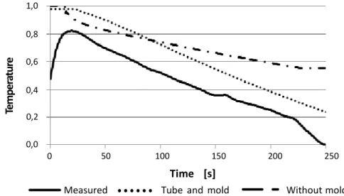
Figure 5:Temperature at point A: measured and estimated with the casting and the CFD codes. In the numerical simulations the configuration shown in Figure 1 c) has been considered. A convective heat transfer coefficients has
been set on the external surface of the pipe.
0,4 0,6 0,8 1,0 Te m pe ra tu re 0,0 0,2
Measured Tube
and mold
Withoutmold
Time [s]
0 50 100 150 200 250
i. Convective heat transfer coefficients
The convective heat transfer coefficient and the related temperature determined in the preliminary simulation have been set on the external surface of the pipe in the model shown in Figure 1 c), and numerical simulations have been performed with both the casting and the CFD codes. Temperatures so estimated are shown in Figure 5.
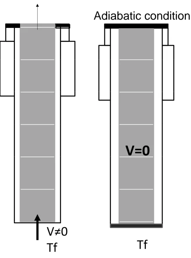
The numerical simulation performed with the CFD code consists of a steady-state condition followed by an unsteady condition: in the first phase schematized in Figure 6 a) the alloy flows in the pipe, then, in the second phase schematized in Figure 6 b) the alloy is motionless. The second phase lasts 0.96 times the total duration of the process.
In the simulation performed with the casting code, the alloy has flowed in the pipe for 0.1 times the total duration of the process, then it has been stopped and the temperature trend at point A has been monitored for 0.96 times the total duration of the
process. The initial condition for the simulations has been determined from the numerical simulation performed with the CFD code in Figure 6 a).
© 2018 Global Journals © 2018 Global Journ G lobal J our nal of Researches in Engineering ( ) V olume XVIII Is sue I V ers ion I 42 Year 2018 J
Interplay of Casting and CFD Software for Improved Accuracy of the Simulation
Figure 6:Conditions simulated with the CFD code: a) first step with a stationary condition, b) final step with an unsteady condition.
Adiabatic condition
V=0
V≠0
Tf
Tf
© 2018 Global Journals G lobal J our nal of Researches in Engineering ( ) V olume XVIII Is sue I V ers ion I 43 Year 2018 Jd) Influence of the grid and of the interface conditions
To investigate the influence of the dimension of the grid, two models havebeen defined: the dimension of the cells in the pipe has been set equal to 5mm (GB), and 2 mm (SG) respectively. In both cases, the standard interfaceconditions have been set.
The casting code requires both boundary and interface conditions, while the CFD code requires
boundary conditions only: it has been investigated the inuence of the interface conditions on the temperature estimated at point A. One simulation, denoted with No Interfaces, has been performed with theSG model and the interface conditions have been set equal to a value higher than that set in the previous simulation: such a value is representative of a condition without contact thermal resistance, and it approaches the condition
Figure 7:Temperatures at point A. Numerical simulations have been performed fordifferent dimension of the grid and interface values.
Interplay of Casting and CFD Software for Improved Accuracy of the Simulation
simulated with the CFD code. The influence of the grid and the interface
conditions has been investigated by means of numerical simulations performed with the casting code on the configuration shown in Figure 1 c).
0,4 0,6 0,8 1,0 Te m pe ra tu re 0,0 0,2 0 50 100 150 200 250 Measured GB GS No interfaces Temperatures so estimated are shown in Figure 7.
i. Heat flux
A campaign of numerical simulations has been performed with the casting code by setting on the external surface of the pipe a heat flux, instead of a convective heat transfer coefficient. The heat flux has been obtained from the preliminary numerical simulation performed with the CFD code and the model shown in Figure 1 c). In this numerical simulation, the standard interface conditions have been set and the grid has cells of 5 mm.
The same condition, that is, a heat flux on the external surface of the pipe, has been set in a numerical simulation performed on the configuration shown in Figure 1 d) which includes the mold: this is the standard configuration.
Temperatures so estimated are shown in Figure 8.
IV.
D
iscussionThe system shown in Figure 1 a) has been analyzed; in particular, the temperature at point A has been monitored. The study has investigated the causes of the difference in temperature between measured and estimated temperatures shown in Figure 2.
• A delay of the thermocouple has distorted the temperature measurement;
• The aluminum undergoes a cooling process while owing in the pipe, then the adiabatic condition on the external surface of the pipe is in-correct;
• The standard boundary conditions are incorrect.
Three hypothesis were made:
© 2018 Global Journals © 2018 Global Journ G lobal J our nal of Researches in Engineering ( ) V olume XVIII Is sue I V ers ion I 44 Year 2018 J
Figure 8:Comparison between measured temperatures and temperatures estimated withthe casting code by setting heat flux on the external surface of the pipe. The configurationsin Figure 1
c) and d)have been considered.
Interplay of Casting and CFD Software for Improved Accuracy of the Simulation
0,4 0,6 0,8 1,0 Te m pe ra tu re 0,0 0,2
Measured Tube
and mold
Withoutmold
Time [s]
0 50 100 150 200 250
Even if a cooling of the alloy in the passage through the tube can not be excluded completely, it can be stated that the difference between measured and estimated temperatures at point A is mainly due to a retard in the measurement. For this, it is correct that the codes estimate a higher temperature of the alloy at the beginning of the process. Setting a lower temperature of the alloy at the entrance of the pipe is incorrect because the temperature of the alloy is diverse and this could result in an incorrect simulation output especially from a metallurgical point of view.
A numerical simulations campaign has been performed to determine the correctness of the standard boundary conditions. Figure 5 shows temperatures at point A: temperatures have been estimated by setting
the same boundary conditions in models representing the configuration in Figure 1 c).
It can be seen that only the temperature estimated with the CFD code match with the measured temperature, and estimated temperatures are higher: higher temperatures estimated with the CFD code were expected because the simulation has been performed from a stationary condition in which the alloy flows in the pipe continuously (Figure 6 a)) and its passage heats the system, while, in the real case the alloy flows for only 0.04 times the total duration of the process. However, it temperature at point A with enough accuracy. On the contrary, there is discrepancy between measured values and those estimated with the casting code.
Given that a greater discrepancy has occurred for the temperature estimated with the casting code, the influence of the grid and the interfaces conditions has been investigated. Results are shown in Figure 7, where it can be noted that the dimension of the grid does not affect the temperature significantly, indeed very similar time-temperature trends have been estimated for models with cells of 2 mm and 5 mm. Also, the interface conditions seem not to affect the temperature at point A: even if the thermal resistance between the elements has been neglected the time-temperature trend has not
changed. Then, the difference in temperature in Figure 2 is not due neither to the dimension of the grid nor to the interface conditions.
At this point, a more severe condition has been set on the external surface of the pipe in the model shown in Figure 1 c) set for the casting code: instead of A test has been performed to check whether
the thermocouple has distorted the temperature measurement; more precisely, to assess the time re-sponse of the thermocouple used to monitor the temperature at point A. In Figure 4, it can be seen that the actual temperature of the alloy has been approached after 0.048 times the total duration of the process from the immersion of the thermocouple, but the time necessary to detect the 99% of the temperature has been calculated and it is about 0.072 times the total duration of the process. For this, the time necessary to detect the maximum temperature of the alloy is longer than the time interval required for filling the mold and for the cooling process beginning, that lasts about 0.04 time the total duration of the process. For this, the actual maximum temperature of the alloy can not be detected by the thermcouple installed at point A.
can be assumed that the CFD code estimates the
© 2018 Global Journals G lobal J our nal of Researches in Engineering ( ) V olume XVIII Is sue I V ers ion I 45 Year 2018 J
Interplay of Casting and CFD Software for Improved Accuracy of the Simulation
a convective heat transfer and the related temperature, a heat flux has been set on the external surfaces of the pipe and the connecting elements.
This condition is more sever inasmuch the computing of the heat flux by the software is not required because the value has been set. In Figure 8, it can be seen that the temperatures (Measured and Without mold) now match even if at the beginning of the process the estimated temperature is higher: this is probably due to the fact that on the upper part of the pipe an adiabatic condition has been set, while in the real case a heat flux occurs towards the mold.
By comparing the time-temperature trends estimated by the casting code shown in Figures 5 and 8, it emerges the difference between imposing a heat convective heat transfer and a heat flux: in this latter case, the initial and final temperature match better and also the trend is detected better. By imposing the heat flux value, releases on the ability of the software to make thermal-fluid-dynamic computing: the heat flux is not computed correctly by the casting code and this is probably due to the shape of the grid elements. The grid defined for the casting code is made of hexahedral elements, while the one built for the CFD code is made of square elements: square is the most suitable shape to the thermal-fluid-dynamic computing in the bound-ary layer. Then, to estimate heat transfer boundbound-ary conditions in casting simulations, it is advisable to make use of CFD codes that are designed for this purpose specifically.
Finally, a final numerical simulation has been performed on the standard configuration shown in Figure 1 d) to check whether the new boundary conditions are appropriate also in the model with the pipe, the connecting elements and the mold. In this way, it has also been possible to assess whether the presence of the mold in the model affects the temperature trends so as to change the results significantly. The time-temperature trend so estimated is shown in Figure 8 and it can be seen that measured and estimated temperatures match also for the configuration in Figure 1 d). The little difference at the end of the process, that is, at 1 time the total duration of the process, is probably due to the cooling system in the mold set in the standard simulation: the cooling system works far from the pipe and the connecting elements, however, it removes heat from the alloy in the mold; then, in this configuration a greater heat flux flows from the pipe towards the mold. As the difference in temperature is only about 100C, it can be stated that the
temperatures match satisfactorily.
V.
C
onclusionsThe study has investigated a casting process. The temperature-time curve at an important injection
point of a mould system has been measured and compared with the values estimated by means of numerical simulations. For the simulations, a casting code and a CFD code have been used. It has been shown that, for the considered system, the casting code is not able to estimate heat transfer correctly if a convective heat transfer coefficient and the related temperature are set, while the estimated temperatures match with measured temperatures if a heat flux is imposed. Given that the estimated temperature is not significantly affected by the interface conditions and the dimension of the grid, the difference in temperature is attributed to the diverse types of grid: in the CFD code, the grid made of squared elements seems to be more appropriate for the thermal-fluid-dynamic computing than a grid made of hexahedral elements.
Then, it is shown the possibility to take advantages of codes in the definition of numerical models for casting simulations.
R
eferencesR
éférencesR
eferencias1. T R Vijayaram, S Sulaiman, A M S Hamouda, M H M Ahmad, Numerical simulation of casting solidification in permanent metallic molds, Vol. 178, 2006, pp. 29-33, http://dx.doi.org/10.1016/j.jmatpro tec.2005.09.025.
2. J Henzel and J Keverian, Comparison of calculated and measured solidification patterns in a variety of castings, AFS (Am. Foundry mens Soc.) Cast Met. Res. J., 1965, pp. 19-30.
3. R D Pehlke, M J Kirt, R E Marrone and D J Cook, Numerical simulation of casting solidification, Trans. Am. Foundry mens Soc., Vol. 81, 1972, pp. 517-523.
4. K G Upadhya, D M Stefanescu, K Lieu, D P Yegar, Computer-aided cooling curve analysis, principles and applications in metal casting, Trans. Am. Foundry mens Soc., Vol. 97, 1989, pp. 61-66.
5. T A Kowalewski, Validation problems in computational fluid mechanics, Computer Assisted Mechanics and Engineering Sciences, Vol. 18, 2011, pp. 39-52.
6. G Strang and G Fix, An analysis of the finite element method, Wellesley-Cambridge, 2008.
7. Y Ohtsuka, K Mizuno and J Yamada, Application of a computer simulation system to Aluminium permanent mold castings, Trans. Am. Foundry mens Soc. Vol. 82, 1989, pp.635-646.
8. S V Patankar, Numerical Heat Transfer and Fluid Flow, Hemisphere Publishing Corporation, New York, 1980.
9. SAE Hand Book, General Information Chemical compositions, mechanical and physical properties © 2018 Global Journals © 2018 Global Journ G lobal J our nal of Researches in Engineering ( ) V olume XVIII Is sue I V ers ion I 46 Year 2018 J
Interplay of Casting and CFD Software for Improved Accuracy of the Simulation
of SAE Aluminium casting alloys, SAE Information Report J 452, Vol. 1, 1991, pp. 10.06-10.14
10. F Moukalled, L Mangani, M Darwish, The Finite Volume Method in Computational Fluid Dynamics: An Advanced Introduction with Open-FOAM and Matlab, 2015.
11. H O Kreiss, O E Ortiz, Introduction to Numerical Methods for Time Dependent Differential Equations, John Wiley & Sons, 2014.
12. S Wannarumon and M Actis Grand, Comparisons of Computer Fluid Dynamic Software Programs applied to Jewelry Investment Casting Process, World Academy of Science, Engineering and Technology 55, 2009, p. 89-95.
13. G C Marshall, Development of a CFD code for Casting Simulations, Final report Space Flight Center National Aeronautics and Space Ad-ministration, 1993.
14. T A Kowalewsky, A Cybulski and T Michalek, Experimental bench-marking for casting problems, Polish Academy of Science, Heat Transfer, 2002. 15. R P Benedict, Fundamentals of Temperature,
Pressure and Air Flow Measurement, 3rd Edition, Omega Press, 1984.
16. J R Davis, Nickel, Cobalt, and Their Alloys, ASM International, ASM Specialty Handbook, 2000. 17. F P Incropera and D. P. Witt, Fundamentals of heat
and mass transfer. John Wiey & Sons, 1985.
© 2018 Global Journals G lobal J our nal of Researches in Engineering ( ) V olume XVIII Is sue I V ers ion I 47 Year 2018 J