Federico Civerchia
PhD Thesis of:
How will edge computing shape
the 5G deployment?
The hardware acceleration
use case
International PhD Program in Emerging Digital Technologies Curriculum: Embedded Systems
Academic Year
2018/2019
How will edge computing shape
the 5G deployment?
The hardware acceleration
use case
Author
Federico Civerchia
Supervisor
Prof. Piero Castoldi
Correlator
Abstract
The recent improvements in the information technology will lead to the new era of the communication (5G) where everything will be connected, where smart and connected objects will be a constant presence in our daily life. Thus, stricter requirements in terms of communication bandwidth and latency have to be sat-isfied to meet the demands of a huge number of connected devices. Instead of the centralized approach, moving the data processing to the edge can improve the performance since it reduces the infrastructure-user round trip time and it saves Cloud bandwidth. However, this decentralization comes at a price though. Moving data computation and communication processing to the network edges improves system scalability and reliability but it requires more local hardware and only a subset of data is analyzed. This means that an edge system does not have global visibility of the information.
This thesis aims at presenting a novel approach to accelerate the 5G infrastruc-ture at the edge. The idea is to exploit hardware acceleration to improve the processing of the protocol stack functionalities and network functions close to the final user. In this way, the bandwidth for the communication between 5G radio infrastructure and the central Cloud can be saved. Moreover, real time application can benefit from the improved computation capabilities by means of hardware offloading.
Considering the latest developments in the embedded systems in terms of com-putational power and lower hardware cost, we envision that edge computing can be exploited to improve 5G infrastructure. Thus, the edge computing is ready to be deployed in 5G architecture, improving the user experience.
To my grandfather and my family
A mio nonno e alla mia famiglia
Contents
Abstract List of Figures List of Tables Chapter 1. Introduction 1 1. From 1G to 5G 12. 5G vision and challenges 5
3. Contributions and outline 6
Chapter 2. Overall 5G architecture description 8
1. 5G RAN Infrastructure 10
2. 5G Datacenter access network 16
Chapter 3. Reconfigurable computing for 5G RAN acceleration 22 1. Acceleration with Reconfigurable Hardware through OpenCL 22
1.1. OpenCL generalities 22
1.2. Specific OpenCL constructs and kernels for reconfigurable
hardware 25
2. Insights on OpenCL kernel optimization for FPGA 28 2.1. OpenCL NDRange kernel optimization 29
2.2. OpenCL SWI kernel optimization 30
3. Related works on OpenCL hardware acceleration 33
4. Implementation 34
5. Performance evaluation and results 44
5.1. Resource usage evaluation 45
5.2. Overall execution time performance evaluation 46
5.3. Computational load evaluation 52
6. Design productivity analysis with OpenCL acceleration 55
Chapter 4. Network functions acceleration at the edge 60 1. Edge node enabling traffic engineering and cyber security 60
1.1. The P4 language 63
1.2. P4 in multi-layer edge nodes 68
1.3. Stateful traffic engineering with P4 70
1.4. Cyber security mitigation with P4 75
1.5. Experimental Evaluation 78
2. Hardware acceleration for Processing Function Virtualization 86 2.1. Processing functions chain as FPGA pipeline 87
2.2. Implementation 88 2.3. Results 90 3. Conclusion 93 Chapter 5. Conclusions 95 List of Acronyms 98 Publication list 101 Bibliography 103
List of Figures
1.1 Evolution of the wireless network: from 1G to 5G 1
2.1 5G transport network architecture 10
2.2 5G architecture 11
2.3 CPRI encapsulation 13
2.4 eCPRI message format 13
2.5 5G functional split 14
2.6 RoE node hierarchy 15
2.7 RoE message format 15
2.8 Downstream user traffic generated with exponential Inter-Departure
Time between packets 16
2.9 Proposed fixed mobile convergence architecture 19 2.10 Silicon selection based on transport and flexibility requirements 21
3.1 OpenCL platform model 23
3.2 OpenCL memory model 25
3.3 Intel Field Programmable Gate Array (FPGA) SDK for OpenCL
workflow 26
3.4 2D example of mapping global IDs, local IDs, and work-group indices
in NDRange 28
3.5 Data parallelization of NDRange kernels 29
3.6 NDRange kernel to add two vectors 30
3.7 SWI kernel pipeline 31
3.8 SWI kernel to add two vectors 33
3.9 DU processing with Option 7-1 functional split 34
3.11 FFT butterfly 38 3.12 Architecture descriptions for a) Single Instruction Multiple Data
(SIMD) and b) Hardware Description Language (HDL) implemented
5G DU processing 39
3.13 System setup 41
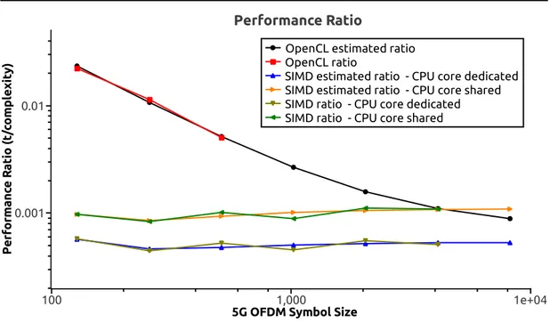
3.14 Performance ratio trend obtained by dividing performance time
measured by OFDM complexity 49
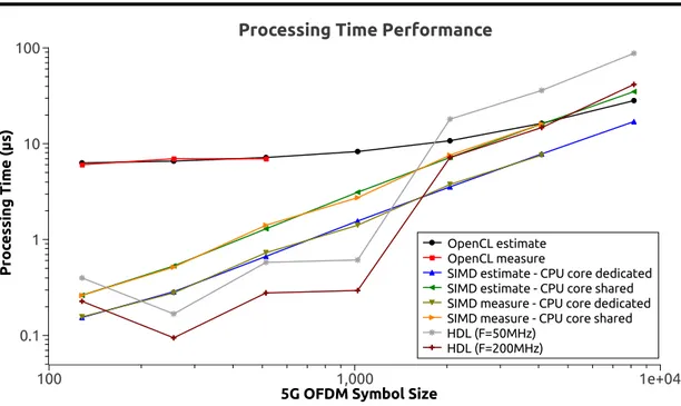
3.15 OpenCL, SIMD, HDL measured and estimated processing time
performance 50
3.16 CPU core computation load for OFDM execution via SIMD 53 3.17 CPU core computation load for OFDM execution via OpenCL offload 54 3.18 CPU core computation load during the switch from software to the
hardware 54
3.19 Design efficiency and implementation chart 56
4.1 Workflow of P4 language compiler and API over programmable devices 63 4.2 Packet-over-optical P4-based edge node 64 4.3 Block diagram of the P4 switch architecture 67 4.4 Data center gateways equipped with P4-based edge node performing
dynamic TE 70
4.5 Dynamic traffic offloading P4 code based on meters and token-bucket 71 4.6 Dynamic optical bypass P4 code based on registers and flowlet
switching 74
4.7 P4 program workflow targeting mitigation on TCP SYN flood attacks 77 4.8 BMV2 results: TE traffic offload behavior 79 4.9 BMV2 results: TE optical bypass behavior 80 4.10 BMV2 results: Wireshark capture of TCP SYN Flood port scan
received and blocked after three attempts by the cyber security P4
program 81
4.11 BMV2 results: scalability performance of the cyber security P4
program in different attack rate scenarios 82 4.12 NetFPGA results: latency as a function of the traffic throughput 83
4.13 NetFPGA results: zoomed version of Figure 4.12 in the 1-9Gbps range 83 4.14 NetFPGA results: latency as a function of installed flow entries 84 4.15 PF implemented in the FPGA processing pipeline 87 4.16 Custom processing pipeline to accelerate PFs-chain to mitigate DDoS
attacks and detect pedestrian 88
List of Tables
1.1 Summary of the wireless network generations 5
1.2 5G frequencies overview 5
2.1 Bandwidth and latency requirements for each functional split 14
3.1 Orthogonal Frequency Division Multiplexing (OFDM) numerology 40
3.2 Terasic DE5-Net board specifications 42
3.3 OpenCL and HDL FPGA resource usage 46
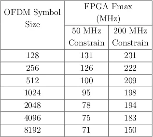
3.4 DU OFDM computation complexity for Option 7-1 split 48 3.5 FPGA timing analyzer frequency report for each OFDM symbol size 52
4.1 P4-NetFPGA latencies in attack and non-attack scenarios 85 4.2 P4-NetFPGA hardware resource utilization 85 4.3 Latency and throughput evaluation for processing pipeline considering
CHAPTER 1
Introduction
In the new era, thought itself will be transmitted by radio. Guglielmo Marconi, New York Times (11 Oct 1931)
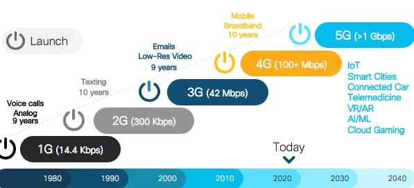
1. From 1G to 5G
Figure 1.1. Evolution of the wireless network: from 1G to 5G 1
Human technologies have never been so connected in the physical world. With the recent progress of the mobile/fixed communication, it will be possible to con-nect up to 7 × 10²³ devices for each square metre of the hearth. This leads to the
new era of the communication where everything will be connected, where smart and connected objects will be a constant presence in our daily life.
Things were significantly different in 1885, when Guglielmo Marconi – the Italian scientist considered the father of the radio communication – proposed the first wireless transmission in the history of science using telegraphs. Marconi could immediately understand the importance of his research, as he wrote in the pa-per Wireless telegraphic communication [Mar09]: ”with regard to the utility of
Chapter 1 - Introduction
wireless telegraphy there is no doubt that its use has became a necessity for the safety of shipping, all the principal liners and warships being already equipped, its extension to less important ships being only a matter of time, in view of the assistance it has provided in cases of danger. Its application is also increasing as a means of communicating between outlying islands, and also for the ordinary purposes of telegraphic communication between villages and towns, especially in the colonies and in newly developed countries”.
Since then, engineers and scientists were working on an efficient way to commu-nicate by means of Radio Frequency (RF) waves. In particular, during 1970s, the invention of hand-held devices, capable of connecting with each other wire-lessly, permitted to standardize the first generation of mobile phone (1G). 1G is based on analog transmission technology designed to provide basic voice service. This first concept of communication considered analog signals without data ca-pabilities and the digital signalling was used to connect radio towers with the infrastructure via Frequency Modulation (FM) at around 150 MHz. Despite this important milestone, 1G technology suffered from a number of drawbacks. The coverage area was poor since the cell size was 2-20 km [Sch03, Sto02] each and sound quality was low. The few providers of the epoch operated with different frequencies without compatibility between each other thus, there was no roaming support. In addition, there was a lack of security since the analog signal cannot implement advanced encryption methods.
The second generation of mobile phone (2G), launched under the Global System for Mobile (GSM) communication in 1991, brought digitalization with respect to the previous generation. Indeed, it provided a digital system alongside the analog transmission. For the first time, calls were encrypted, the sound was significantly clearer with less noise in background and the cell coverage area increased up to 35 km. Also Short Messages Service (SMS) and Multimedia Messages Service (MMS) services were implemented to offer new functionalities for the end-users. Moreover, the allocation of the spectrum was optimized with modulation tech-niques that will be also used in the next generations such as Time Division Mul-tiple Access (TDMA), Frequency Division MulMul-tiple Access (FDMA) and Code Division Multiple Access (CDMA) [EVBH08]. The 2G evolved in 2.5G in 1999, better known as Enhanced Data GSM Evolution (EDGE), which was closer to the next generation (i.e., 3G) in terms of Quality of Service (QoS) and through-put (up to 300 Kbps against 64.4 Kbps of the GSM) [BMC04]. Despite the
Section 1 - From 1G to 5G
enhancements with respect to 1G, also 2G had many drawbacks, especially inter-ference issues due to frequency reuse. Also TDMA shown its limitation in case of unfavorable terrains, topographic or electromagnetic conditions that can bring to communication failure [EUO+18].
The third generation of mobile phone (3G) starts with the introduction of the Universal Mobile Terrestrial/Telecommunication Systems (UMTS). This com-munication era provided dedicated networks to improve throughput and reduce latency. Moreover, many services started from this generation such as global roaming and enhanced voice quality. The data transfer capability increased up to 4 times faster than 2G, enabling multimedia services like video streaming and Voice over IP (VoIP). Users could access data from any location in the world as ”data packets” since the network evolved from circuit commutation to packet commutation [Fag14]. This network switching technique enables the possibility of encapsulate data into a packet that can be routed from a source to a desti-nation. In this scenario, no dedicated circuit is necessary to forward the traffic as considered in the circuit switching paradigm. The most significant drawback of this generation relies on the energy consumption since more power is neces-sary, with respect to 2G, to sustain the communication between user devices and cells [HT05]. In order to enhance data rate in existing 3G networks, another two technology improvements are introduced to network: High Speed Down-link/Uplink Packet access (HSDPA/HSUPA) and High Speed Packet Access plus (HSPA+). These technologies refers to the advanced 3G network (i.e., 3.5G) that can support up to 42 Mbps data rate.
The fourth generation of mobile phone (4G) is the present generation of com-munication. 4G architecture is design to improve the packet-switched traffic with seamless mobility, QoS and latency/throughput communication. The main components of the architecture are the evolved Node B (eNB) and the Evolved Packet Core (EPC). The first one is dedicated to acquire the user data and process them according to the 4G protocol stack. The EPC is responsible for the communication management and it is composed by four entities: Home Sub-scriber Server (HSS), Service Gateway (SGW), Packet Data Network Gateway (PDNGW) and Mobility Management Entity (MME). The HSS is a database that contains user-related and subscriber-related information. SWG is the con-nection point between the radio-side and the EPC while PDNGW enables the communication between EPC and the external IP network. MME handles the
Chapter 1 - Introduction
signalling related to mobility and security for network access, interacting with the HSS [R+13, Kha09]. To achieve the minimum communication latency, ad-vanced techniques are introduced like Multiple Input Multiple Output (MIMO) and OFDM. The main drawback of the system is the interference due to the crosstalk from two different transmitters using the same channel. This problem is a constant presence from 2G, where it represented the main issue for a good communication, to 4G and also 5G. However, many interference coordination schemes and interference-aware receivers have been developed from 2G to 4G to significantly reduce the problem. For instance, we can consider the Network Assisted Interference Cancellation and Suppression (NAICS) that considers ad-vanced receivers capable of detecting interfering transmission, improving the QoS of the overall network [HT09, ADF+13].
Other wireless technologies are part of 4G era, such as WiFi, Bluetooth and Zig-bee. These protocols are thought for both improving end-user communication and introducing Internet of Things (IoT) applications. This represents an im-portant improvement in terms of flexibility and compatibility, considering that 2G does not even support the roaming. This aspect is also underlined by the backward compatibility of the 4G systems with the previous generation of mobile phone.
So far, each generation of mobile technology brought along with it improvements that have changed our daily lives. 1G enabled the first communication, 2G en-hanced 1G by means of digitalization and improving sound quality, security and network capacity. 3G introduced the mobile broadband for internet services, while 4G addressed the growing demand of bandwidth dedicated to each user. The fifth generation of mobile phone (5G) should address the limitations of the 4G providing high bandwidth and low latency for a large number of users. More-over, it should also address a wide range of services, especially in the field of machine-to-machine communication [Yil16]. Indeed, the effort that the scien-tific community is dating towards the deployment of 5G leads to think that the next generation will be disruptive. It will provide extremely low latency/high bandwidth connection for many applications, from HD streaming to autonomous driving. In other words, connections everywhere at anytime with higher capacity, higher data rate, lower end-to-end latency, massive device connectivity, reduced cost and consistent QoS provisioning compared with 4G [Ben14].
Section 2 - 5G vision and challenges Generation Speed Technology Time Period Features
1G 14.4 Kbps AMPS, NMT,
TACS 1970-1980 Voice only, no roaming 2G 64.4 Kbps TDMA,CDMA 1990-2000 Data + Voice, roaming 2.5G 170-300 Kbps EDGE, GPRS 2001-2004 Multimedia services and
streaming starts 3G 1-3 Mbps UMTS, CDMA 2004-2005 Multimedia services and
streaming support 3.5G 14-42 Mbps HSDPA, HSUPA,
HSPA+ 2006-2010
Higher throughput and speeds 4G 100-300 Mbps OFDM 2010-now High definition
streaming and multimedia 5G Gigabits Under study 2020 High speed and throughput
for large number of devices
Table 1.1. Summary of the wireless network generations
2. 5G vision and challenges
The increasing number of connected devices brings to a big rise of the traffic volume. 5G has the role to address such enormous traffic, providing low laten-cy/high throughput communication, network scalability and flexibility as well as low system complexity and power consumption [OBB+14]. To cope with such
requirements, 5G envisions to improve carrier frequencies with larger bandwidth, number of antennas and the network infrastructure. The need to change fre-quency is due to the scarcity of the free frequencies remained in the bandwidth considered so far. Table 1.2 summarizes the multi-layer frequency approach pro-posed for 5G [LTRa+18].
Frequency Range Layer Note
High frequencies
Above 6 GHz Super Data Layer Extremely high data rates Medium frequencies
2-6 GHz Coverage & Capacity Layer
Compromise between capacity and coverage Low frequencies
Below 2 GHz Coverage Layer
Lower data rates to improve coverage area Table 1.2. 5G frequencies overview
Chapter 1 - Introduction
An increasing number of antennas permits to enhance the network densification which corresponds to more nodes served per unit area. The novelty in this field is to include small cells alongside distributed antenna systems. Pico-cells (i.e., hundreds of meters) and femto-cells (i.e., some meters like home WiFi range) are considered as small cells. Antenna distributed systems are similar to pico-cells from a coverage point of view but the processing is demanded to a central site that is connected to many antennas. In this scenario, the transmission power is lower, reducing the power consumption, with the advantage of reaching more connected devices due to densification [PCK12]. Power consumption saving is also achieved by the energy harvesting that can maximize the lifetime of the wireless devices. The idea behind this concept is to transmit data via radio signals that can also recharge the devices. Indeed, in RF energy harvesting, radio signals with frequency range from 3 KHz up to 300 GHz can carry energy in form of electromagnetic radiation [LWN+14]. However, the benefits of the
increased number of cells pose challenges for the mobility. A moving node of the network has to pass and interact with many cells, thus the passage between cells is frequent and it can cause a lack of synchronization. Indeed, the handoff can be particularly challenging since beams (i.e., messages used for synchronization) have to be aligned to communicate. Actually, such handoff does not exist at layer 3 (i.e., IP layer) in the 5G communication, but many coordination techniques are under study where the user can communicate with many base stations to achieve the optimal synchronization [ABC+14].
Regarding the 5G architecture improvements, this thesis focuses at this aspect, thus an exhaustive description of the infrastructure will be provided in the first chapters of this work.
3. Contributions and outline
This thesis aims at presenting a novel approach to accelerate the 5G infrastruc-ture at the edge. The idea is to exploit hardware acceleration to improve the processing of the protocol stack functionalities and network functions close to the final user. In this way, the bandwidth for the communication between 5G radio infrastructure and the central Cloud can be saved. Moreover, real time application can benefit from the improved computation capabilities by means of hardware offloading. In Chapter 2, the overall architecture of the 5G is intro-duced. When referring to 5G communication, its architecture is fundamental to
Section 3 - Contributions and outline
clearly describe the possible improvements that can be addressed by means of hardware offloading. In particular, this chapter describes both 5G Radio Access Network (RAN) architecture and the access network for the datacenter. Hard-ware acceleration can enhance both solutions that are considered as case studies in this work.
Chapter 3 focuses on the reconfigurable computing approach that can be exploited to accelerate the functionalities of 5G protocol stack. Reconfigurable computing is paradigm that considers programmable hardware acceleration of software al-gorithms. The idea is to enhance the processing with very flexible hardware platform like FPGA with the supervision of the software that has the role to offload the data and control the hardware processing. The approach proposed in this Chapter is based on Open Computing Language (OpenCL) for FPGA hardware platform. This represents the first study to evaluate OpenCL hardware acceleration in the context of a 5G base station.
Chapter 4 leverages on the improvements of the network functions at the data-center access network. The potential of the Programming Protocol-independent Packet Processor (P4) open source language, recently introduced by the inventors of OpenFlow, is considered to program the behavior of a switch located at the edge of the network access infrastructure. Special effort is dedicated to motivate and apply P4 within a multi-layer edge scenario. Both Traffic Engineering (TE) and cyber security scenarios are considered as network functions to be improved by means of P4 language. The TE use case is tested with a P4 software switch while the cyber security scenario considers an hardware switch, based on FPGA and compatible with P4 programs. Moreover, FPGAs are also used to accelerate processing functions at the edge, exploiting a purely hardware pipeline. In this way, the computation is completely demanded to the hardware without offload-ing the data from software. An host application is responsible for monitoroffload-ing the correct operations execution by changing the parameters of the hardware pipeline.
CHAPTER 2
Overall 5G architecture description
The fifth generation of mobile communications (5G) brings with it unprecedented challenges that require thinking in new ways to meet the aggressive performance goals. Indeed, it will revolutionize our world with enormous data transfer capac-ities that will power the future of smart ccapac-ities, robotics and the next billions con-nected things. In addition, the 5G infrastructure will provide tailored solutions such as automotive, agriculture, healtcare, etc [Moh16]. Thus, it is necessary to improve the networking service for all the stakeholders. Strong industry partners engage in all stages of development, starting with early research, contributing to standards development, developing technology and ultimately deploying net-works.
To meet the requirements of the 5G, the network operators have to allocate re-sources for each kind of service deployed, which reflects to the implementation of orchestrator functions to manage the entire communication. Thus, each service will have a dedicated logical network called network slice. This feature represents one of the main novelty of 5G to address all the tasks and dedicate resource for each business. The ubiquitous approach considered for the 5G infrastructure have to operate in an energy efficient way to contain the power consumption of the network [Kal18]. In such environment, the following design objectives can be summarized to understand the challenges of this revolution in the wireless communication.
Spectrum availability: this feature is essential to support the huge amount of data demand. Thus, 5G network have to operate considering wider spectrum than the actual 4G technology. Indeed, the frequency range can be divided in three different parts: below 2 GHz for better coverage area, 2-6 GHz for higher throughput and super/extremely high frequency (over 6 GHz, up to 60 GHz) for military and aerospace applications [WLH+14].
Efficient data processing: the improvements of the last years about data pro-cessing permit to reduce the propro-cessing time of the 5G tasks to meet the latency requirement which represents a really strict constraint in the next generation of mobile phone. In particular, the use of different platforms such as General Purpose computing on Graphics Processing Unit (GPGPU) or FPGA, that exploit the massive parallel computing, can reduce significantly the computation time [CLS+08].
Addressing air interface variances: the number of wireless protocol is grow-ing to support a large number of application, especially in the IoT en-vironment. This means that interference can happen when enabling all the protocols. In this scenario, the physical layer has to be rethought with different waveforms and numerologies to meet the variances of the air interface. Moreover, an efficient inter-networking between 5G and 4G is essential to maintain the compatibility with the previous technol-ogy [CSSK+15].
Multi-connectivity: multiple access points can simultaneously configure ra-dio resources to a given user device, introducing link diversity. This permits to improve the reliability and many schemes are under study to improve the number of different technologies connected simultane-ously [RRM+16].
Convergent fixed-mobile networking: in the new era of communication, the same physical network has to be shared between wired and wireless user connections. Thus, virtual connection may operate in parallel to ensure connectivity among all the customers, exploiting the network slice par-adigm. Moreover, a Software Defined Networking (SDN) orchestrator allows to have an ordinate management of the same physical infrastruc-ture [EGS+15].
Traffic differentiation: complex algorithms for traffic differentiation will be im-plemented to meet the stringent constraint regarding the QoS. Separa-tion and prioritizaSepara-tion of the resources are the keywords to be taken into account when deploying this feature [G+17].
To address the above objectives, an intelligent transport network has to be de-ployed and enhanced automation capabilities in the operation and management represent a key requirement. Thus, Figure 2.1 shows the complete transport net-work, from the 5G RAN up to the datacenter access with the management and
Chapter 2 - Overall 5G architecture description
Figure 2.1. 5G transport network architecture
orchestration layer and the Transport Intelligence Functions (TIFs) [DDGF+18].
This chapter focuses on the state-of-the-art of such architecture and, in particu-lar, the 5G RAN is described in Section 1 while the datacenter access network is deepened in Section 2.
1. 5G RAN Infrastructure
The 5G infrastructure must provide high level of efficiency, flexibility, and scal-ability in the RAN. Indeed, applications such as enhanced mobile broadband (eMBB), massive machine type communications (mMTC), and ultra reliable low latency communications (URLLC) [GT] demand requirements that the previous generation (4G) mobile communications cannot satisfy. Thus, the RAN has to be re-thought.
In 4G, the eNB represents the hardware and software located at the antenna site, enabling the wireless access of many mobile devices (e.g., smartphones, tablets, PCs, etc.) to the mobile network infrastructure. Here, the protocol stack and signal processing, which handles the data from mobile devices are resolved. This approach has many limitations, in particular for what concerns flexibility and scalability, since the eNB is structured to provide connectivity for a certain num-ber of devices and it is not able to adjust the power consumption (e.g., putting
Section 1 - 5G RAN Infrastructure
in standby some functionalities) in case of less users connected. On the contrary, if an area requires a higher number of users to be served, another eNB has to be deployed.
An important novelty of 5G is splitting the eNB into two different entities: the Central Unit (CU) deployed in central locations and the Distributed Unit (DU) deployed near the antenna. This architecture is called Next Generation RAN (NG-RAN) or C-RAN, where the ”C” stands for both centralized and cloud. In-deed, CU and DU can be even virtualized and deployed in the cloud [GKG+19].
Likewise, the eNB in the 4G infrastructure evolves in next generation eNB (gNB). Centralizing the CU leads to several benefits including economy of scale, reduc-tion of the maintenance for the cell towers, and performance improvement due to better coordination between antennas. Economy of scale refers to the possibility of deploying less hardware devices compared to the actual 4G infrastructure. For instance, a single large router for network access can serve the CU rather than many little routers serving a single eNB. In this way, the CU can be designed to be able to move router ports from under-utilized CUs to over-utilized CUs. The maintenance can be reduced by upgrading the software of centralized CUs. Finally, the performance in terms of lower call drop rates and downlink data rates are 30% improved with the centralized approach [Per17].
Chapter 2 - Overall 5G architecture description
The NG-RAN architecture is depicted in Figure 2.2. Here, many gNBs are con-nected to the 5G Core (5GC) which manages the User Equipment (UE) com-munication with the Data Network (DN). The link between the gNBs and 5GC is the NG interface, which corresponds to the backhaul. Each gNB consists of a CU, gNB-CU in Figure 2.2, connected to a DU, gNB-DU in Figure 2.2, by means of the F1 interfaces, which is the midhaul interface. This interface is the link between DU and CU. Often, based on the DU location, an additional element, including only the Radio Frequency (RF) functions (e.g., filtering, mixing, up-conversion/downconversion, Digital to Analog Conversion) called RRU (Remote Radio Unit), is deployed and it is connected to the DU by the, so called, fron-thaul interface. Many interfaces have been defined to transmit the data in the fronthaul and midhaul links, such as Common Public Radio Interface (CPRI), ethernet-based CPRI (eCPRI) and Next Generation Fronthaul Interface (NGFI). In particular, CPRI, eCPRI are protocols defined for the fronthaul data trans-port while NGFI is designed for the midhaul communication. CPRI is a radio interface developed by several leading telecom vendors to transport sampled RF data between the DU and the CU. In Figure 2.3, the option 1 CPRI encapsula-tion is presented as an example to understand the CPRI frame structure. Here, the In-phase/Quadrature (I/Q) samples are encapsulated inside a frame which lasts 260 ns (1/3.84MHz). Each I/Q sample is encoded with 8-bit word and 16 words are transmitted in a single frame (called chip). Thus, the transmission throughput (TT) can be calculated as follow:
T T = 1 chip × 16 words × 8 bit × 3, 84 M Hz ×10
8 = 614.4 M bps (1)
Where 108 is the factor due to the 8B/10B line coding for the error correction/de-tection used in CPRI option 1 [Spe].
The utilization of native CPRI in networks, instead of point-to-point connections only, implies the development of dedicated hardware not compatible with current MAC and PHY standard protocols, potentially causing cost inefficiency. Thus, transporting CPRI frame over eCPRI has recently increased interest because of its flexible, cost-effective deployment, easy integration with the current high speed ethernet-based optical networks. Figure 2.4 shows how eCPRI message is mapped into transport network layer payload (e.g. UDP/IP or Ethernet) [C+17].
Section 1 - 5G RAN Infrastructure
and CU functional splits have been described for the use of Ethernet based fron-thaul. Moreover, the bandwidth requirements for CPRI are high and the link rates are currently limited without the possibility to scale up. Bandwidth is not the only restrictive aspect, in fact CPRI also requires very strict latency constraints that do not permit to transport data for long distance [dlOHLA16].
Figure 2.3. CPRI encapsulation
Figure 2.4. eCPRI message format
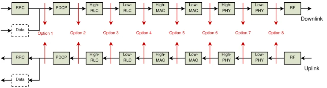
Regarding the midhaul, as the gNB is splitted into CU and DU, so are the protocol stack functionalities. This is an important novelty of 5G called functional split where the functionalities can be splitted according to the scheme in Figure 2.5. The 3GPP association established the requirements, in terms of both latency and bandwidth, reported in Table 2.1 [3GP17], for the communication network
Chapter 2 - Overall 5G architecture description
Protocol Split Option Required bandwidth Max allowed one-way latency
Option 1 DL: 4Gb/s UL: 3Gb/s 10ms
Option 2 DL: 4016Mb/s UL:3024 Mb/s 1.5∼10ms
Option 3 lower than option 2 for UL/DL 1.5∼10ms
Option 4 DL:4000Mb/s UL:3000Mb/s approximate 100µs
Option 5 DL: 4000Mb/s UL: 3000 Mb/s hundreds of microseconds
Option 6 DL: 4133Mb/s UL:5640 Mb/s 250µs
Option 7-1 DL:10.1∼22.2Gb/s UL:16.6∼21.6Gb/s 250µs Option 7-2 DL:37.8∼86.1Gb/s UL:53.8∼86.1 Gb/s 250µs Option 7-3 DL:10.1∼22.2Gb/s UL:53.8∼86.1Gb/s 250µs
Option 8 DL:157.3Gb/s UL: 157.3Gb/s 250µs
Table 2.1. Bandwidth and latency requirements for each func-tional split
connecting DU and CU as a function of the considered functional split. As reported in Table 2.1, the requirements are stricter when most of the functions is implemented in the CU.
RRC Low-PHY High-RLC High-PHY Low-MAC PDCP Low-RLC High-MAC RF Data RRC Low-PHY High-RLC High-PHY Low-MAC PDCP Low-RLC High-MAC RF Data
Option 1 Option 2 Option 3 Option 4 Option 5 Option 6 Option 7 Option 8
Downlink
Uplink
Figure 2.5. 5G functional split
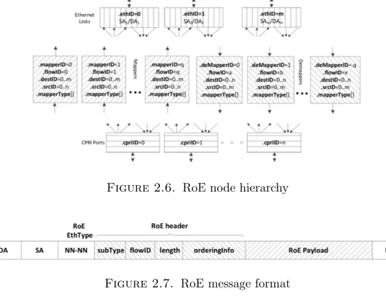
Several other ongoing efforts are investigating on midhaul solution such as the Institute of Electrical and Electronics Engineers (IEEE) 1914 Working Group with the NGFI. In NGFI, the midhaul traffic depends on the functional split implemented and bandwidth and latency constraints may vary according to the functional split used [Z+15]. NGFI has identified both lower and higher possible functional splits. It is claiming to be the protocol that supports key technologies for 5G such as statistical multiplexing and radio interface technological neutral-ity. The NGFI is based on Radio over Ethernet (RoE) encapsulation, which is summarized in Figure 2.6 and Figure 2.7 where both hierarchy and RoE encapsu-lation format are presented. The RoE node maps the CPRI ports into Ethernet links exploiting the mapper/e-mapper process blocks. The packet that has to be
Section 1 - 5G RAN Infrastructure
sent over Ethernet link is depicted in Figure 2.7. The RoE payload contains a flow of I/Q samples for a single antenna carrier of a group of antenna subcarri-ers [19118].
Figure 2.6. RoE node hierarchy
Figure 2.7. RoE message format
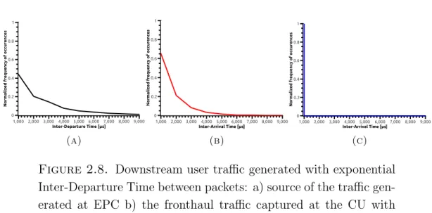
An experimental characterization of the midhaul traffic by considering different gNB functional splits (i.e., Option 8, Option 7-1 and Option 2) is detailed below. In particular, the impact of the user traffic, injected on midhaul with different inter-departure time distributions, is evaluated. The utilized mobile network software is OpenAir Interface (OAI) which uses NGFI technique for the midhaul communication [NMM+14].
The experiment is coped with sending data between the gNB and the UE. Here, the sender component of D-ITG tool (ITGSend) were running at EPC to generate downstream UDP traffic, and the receiver component of D-ITG tool (ITGRecv) were running at UE to receive UDP traffic [AGE+04]. The Wireshark capture
was initiated at DU to capture the midhaul traffic for Option 7 functional split, where the Wireshark capture was initiated at CU to capture the midhaul traffic for Option 2 functional split. Figure 2.8 shows the user traffic generated by following negative exponential distribution from gNB to UE. In particular, the
Chapter 2 - Overall 5G architecture description N o rm a li z e d f re q u e n c y o f o c c u re n c e s 0 0.2 0.4 0.6 0.8 1 Inter-Departure Time [μs] 1,000 2,000 3,000 4,000 5,000 6,000 7,000 8,000 9,000 (a) N o rm a li ze d f re q u e n cy o f o ccu re n ce s 0 0.2 0.4 0.6 0.8 1 Inter-Arrival Time [μs] 1,000 2,0003,000 4,0005,000 6,0007,000 8,000 9,000 (b) N o rm a li ze d f re q u e n cy o f o ccu re n ce s 0 0.2 0.4 0.6 0.8 1 Inter-Arrival Time [μs] 1,000 2,000 3,000 4,000 5,000 6,000 7,000 8,000 9,000 (c)
Figure 2.8. Downstream user traffic generated with exponential Inter-Departure Time between packets: a) source of the traffic gen-erated at EPC b) the fronthaul traffic captured at the CU with Option 2 functional split c) the fronthaul traffic captured at the DU with Option 7 functional split
behaviour of the inter-departure time of the traffic generated at the gNB side is depicted in Figure 2.8a. Then, the traffic is captured with help of the Wireshark at CU with Option 2 functional split and the inter-arrival time of the traffic follows the negative exponential distribution, as shown in Figure 2.8b. However, in Figure 2.8c, it is shown the inter-arrival time of the traffic, related to the lower layer functional split (Option 7-1), is independent on the user traffic. In fact, the distribution no longer follows the negative exponential trend. The experiments for uplink communication and with Option 8 were performed, but not presented because they follow the same behaviour of downlink communication and Option 7-1 respectively. Thus, the midhaul traffic, based on NGFI protocol, is independent on the user traffic profile when the lower functional splits (i.e., Option 8 and Option 7-1) are considered. Whereas, the midhaul traffic is dependent on the user traffic when the higher functional split (i.e., Option 2) is considered.
2. 5G Datacenter access network
Besides the RAN, the datacenter is the other core of 5G transformation. At the beginning of this Chapter we listed the main objectives of the architecture based on the efficiency, scalability, flexibility and intelligence. Thus, a question rises: what kind of datacenter is able to meet the requirements of the 5G? To answer the question, we list the main features to build a datacenter in the 5G era [Gu18].
Section 2 - 5G Datacenter access network
Open: the layers of the datacenter should be open to be accessible from the research community for continuous enhancements. Indeed, the present datacenter infrastructure is based on frameworks like Openstack and database queries are inspired by standards like Hadoop, Spark, MySQL and Redis. These technologies are still under development to offer the best performances in the 5G environment.
Efficient: the latency and bandwidth requirements are 100 times stricter than the last generation of mobile phone. Moreover, with the support of net-work slicing, many services can be deployed in parallel and most of them are critical in terms of latency and reliability like ultra-HD video stream-ing or intelligent transport system. For these reasons, hybrid solutions are investigated like System on Chips (SoCs) based on ARM/Intel cores and FPGA, GPGPU and Neural network Processing Unit (NnPU). Re-configurable computing could also improve the software performances and bottlenecks, exploiting the hardware offloading of the tasks con-trolled by the software. This solution is also suitable to accelerate the processing of the huge amount of data coming from the IoT environ-ment. Indeed, GPGPU/FPGA clusters can accelerate the computation by means of massive parallel computing.
Flexible: the orchestration of the network slices has to adapt to the changes of the 5G network. Indeed, all the services such as including capacity, service configuration, network elements and service applications should be deployed as quick as possible. Virtual machines to handle the com-munication can be easily added or removed from the network, thus the flexibility is an important feature to follow the changes.
Distributed: in the 5G environment, most of the services are cloud-based (e.g., IoT core services, big data, deep learning, etc.) but many other function-alities can run in an edge datacenter, reducing the computation at the central location. Thus, ubiquitous computing (i.e., the capacity of the computing to appear everywhere when needed [Wei91]) can improve the processing by moving the functionalities at the edge. Such a computing should be controlled by a central intelligence and deployed to support many services like object detection and recognition in surveillance videos, 3D rendering, real-time operations, gaming and much more.
Chapter 2 - Overall 5G architecture description
Intelligent: this feature represents one of the main keys for the 5G infrastruc-ture. Indeed, the 5G network manager has to be flexible and to adapt to the network changes. To achieve this goal, a powerful Artificial Intel-ligence (AI) architecture should be considered along with heterogeneous computing hardware, including GPGPUs, FPGAs and NnPUs, capable of implementing high computational capacity algorithms.
To meet such requirements, a new idea of datacenter is rising based on the Network Function Virtualization (NFV) functionalities that permit to reach a higher levels of flexibility with a rapid deployment. Indeed, many services starts to be deployed with the NFV approach, such as fixed and mobile core network or the 5G RAN as well as the traffic analysis, optimization and security func-tions [HPS+15, OLAL+17, AKL+18]. Figure 2.1 shows the datacenter access
network for the 5G environment. The access aggregation entity corresponds to the edge computing node of the datacenter that is physically close to the users. Its location represents a novelty in the architecture and permits to accelerate the data processing in order to only send metadata to the cloud central node [Yu16]. The metro network domain provides connectivity between the edge node and the national backbone, as well as to the global internet from the central cloud node. At the metro network level, the data coming from many edge nodes are collected exploiting the optic fibers based on the Dense Wavelength-Division Multiplex-ing (DWDM). Such a technology can aggregate up to 100 wavelength channels over the same fiber to accommodate the large aggregated traffic from the access branches. Moreover DWDM permits to reach an incredible high data through-put (around Tb/s) in a single optical fiber [DGE+15]. This aspect enables the
possibility to easily aggregate all the traffic coming from large variety of services, from entertainment to IoT, 5G and much more.
Finally, the central cloud node located far from the regional and edge nodes, it is the collector of many services like deep processing, networking and other com-puting resources.
Focusing on the cloud edge node, the NFV approach is more suitable to be de-ployed at this level of the datacenter architecture since the edge node has to adapt to the services changes based on the users requests. Thus, the flexibility of the NFVs may help to follow the network modifications. Moreover, the de-ployment of the NFV functionalities in such instance allows to improve resilience, latency and jitter, as well as to reduce the computational load in the metro and
Section 2 - 5G Datacenter access network
Figure 2.9. Proposed fixed mobile convergence architecture
central nodes. Many researches are still conducted to standardize this new ap-proach for the datacenter edge node, called Central Office Re-architected as a Datacenter (CORD) [PASA+16, ASP15], where Next Generation Central
Of-fice (NGCO) will host the edge node for new mobile network [BMW18]. Such technological upgrade coincides with the recent replacement of the copper links with optical fiber, especially in the Last Mile (i.e., the connection between the edge node and the users). As discussed above for the metro nodes, the fiber can be also aggregated into the NGCO that is capable of serving few thousands of con-nections. Moreover, the NGCO can collect the data from both wired and wireless communication, implementing the 5G and fixed mobile convergence [BFS+17].
To achieve the convergence, common policy and user data management between fixed and mobile network had to be enabled. Moreover, NFV approach can improve the convergence by means of resource sharing and avoiding the network duplication due to fixed and mobile networks. The deployment of the convergence at the edge node enables the possibility to achieve the fully seamless datacenter architecture since the data are no longer separately treated based on the com-munication medium, but they are collected and sent to the cloud central node. Figure 2.9 shows the possible architecture for the convergence [GBNM+18].
Many other features can be deployed in the NGCO like services prioritization or dynamic service provisioning but a deepening is necessary for data process-ing and cyber security. Regardprocess-ing data processprocess-ing, many NFVs are dedicated
Chapter 2 - Overall 5G architecture description
to data processing at the edge, thus they can be defined as Processing Function Virtualizations (PFVs). The adoption of the programmable hardware offloading may speed up advanced applications and processing functions. For cyber secu-rity scenario, one of the main functionalities is the mitigation of the Distributed Denial of Service (DDoS) attacks that can generate excessive bandwidth and it can make the network unstable. The mitigation of these attacks at the edge node has an enormous benefit since the attack is immediately resolved at the edge of the network, without spreading up to the central node. NFV can be deployed to address problems of security mitigation to neutralize possible strikers. As discussed for data processing, such a mitigation could be done with the help of other platforms like Application Specific Integrated Circuits (ASICs), FPGAs or Network Processing Units (NPUs). Indeed, co-design approach can improve data processing and mitigation problems since it combines the benefit of both hard-ware and softhard-ware approaches. NFVs are dynamically deployed and they abstract the hardware resources while hardware platforms improves the processing perfor-mance in terms of processing time and throughput. Typically, ASIC utilization is expensive to design and it is not reconfigurable, thus its use is targeted for lower lever of the ISO/OSI protocol stack, where the protocols and standards are well defined. However, for application layers that are still under develop-ment, the software approach is essential to quickly dispatch improvements. For these reasons, new languages start to have success since they permit the hard-ware/software communication, enabling the co-design approach. In this scenario, P4 language is capable of closing the gap since it can be compiled for several hardware platform like FPGA or NPU, eliminating the portability issue of the hardware. Moreover, it allows the hardware processing with the support of the software communication. In this scenario, P4 implementation is tailored on se-curity application since it allows to process network data at high throughput with the addition of the software control to enable, disable and update mitiga-tion algorithms when needed. The venue of this co-design languages permits to overcome the threshold of hardware/software application so far. In general, hardware approach like ASIC on NPU is considered for central cloud node (i.e., core) deployment to process huge amount of data dispatched towards the central node. Figure 2.10 shows boundary of the NFV and hardware usage in the data-center network access [BMW18]. However, NFVs are considered to dynamically
Section 2 - 5G Datacenter access network
Figure 2.10. Silicon selection based on transport and flexibility requirements
adapt the services close to the end user with unpretentious throughput or pro-cessing time. Co-design approach should enable the possibility of using hardware architecture at the edge, improving the processing of the NFV and maintaining software flexibility. In this way, also security issues could be locally addressed, without loading the central cloud node.
CHAPTER 3
Reconfigurable computing for 5G RAN acceleration
In this Chapter, the reconfigurable computing approach is considered to accel-erate part of the 5G network functionalities. In particular, it focuses on the acceleration of the 5G OFDM task in the DU by means of OpenCL framework. The OpenCL performance are then compered with the software SIMD and hard-ware HDL approaches.
1. Acceleration with Reconfigurable Hardware through OpenCL
1.1. OpenCL generalities. OpenCL is a framework for writing programs that can be executed across heterogeneous platforms such as Central Processing Units (CPUs), GPGPUs, Digital Signal Processors (DSPs) and FPGAs. OpenCL specifies a programming language (based on C99) for programming these devices and Application Programming Interface (API) to control the platform and ex-ecute programs from the host side (i.e., computational unit on which the host program runs to control the OpenCL device). Originally thought as the intersec-tion between GPGPU and CPU parallel programming, OpenCL is now the best candidate as heterogeneous computing language, especially after the implementa-tion of the FPGA support. It supports different types of parallelism to be suitable for all the hardware platforms. On the other hand, each platform reaches the best performance exploiting a certain type of parallelism. For this reason, the main advantage of OpenCL framework is the possibility to write a single program that can run on heterogeneous platforms seamlessly, even if many optimizations have to be done for each platform to reach the best performance [SGS10]. Moreover, it exploits the parallel computing approach which enhances the application per-formance. Two main parallel programming models are possible with OpenCL: task parallelism and data parallelism. In the first one, the application can be decomposed in several tasks with different computation loads. Each task can be mapped into Processing Elements (PEs), that can run concurrently. This ap-proach is very useful when there is no data dependency between tasks. However,
Section 1 - Acceleration with Reconfigurable Hardware through OpenCL
Host
PEn
PE1 PE2 PEn
PE1 PE2 PEn
PE1 PE2 CU1
CU2
CUn
OpenCL Device
Figure 3.1. OpenCL platform model
it suffers of load balancing drawback since the processing finishes only when the last PE finishes its task. Thus, an unbalanced loading brings to a loss of perfor-mance. In data parallelism model, the application can be seen as collection of data elements that can be processed concurrently. This means that a single task can be applied to each data element. This model is possible when a processing on arrays or matrix is needed since each element of the structure can be easily computed by a single task [MGMG11].
The OpenCL platform model is shown if Figure 3.1. Here, a single host acts as a master capable to interact with many OpenCL devices which are the components where a stream of instructions execute. Such a stream of instructions is called kernel and it represents the program executed by the OpenCL device. Each device is called Compute Devices (CDs) and it can be a CPU, GPGPU, DSP or FPGA. Each CD can be divided in OpenCL Compute Units (OpenCL CUs) which are further divided into PEs. The PEs represent the smallest OpenCL computation units and all the processing run within the PEs [GO11].
Chapter 3 - Reconfigurable computing for 5G RAN acceleration
OpenCL application. The host program has the role to initialize and interact with the kernels by using the standard OpenCL API [HM15]. It establishes the context for the kernels as well as the command queues to be sent to the device. Moreover, it defines the memory objects which are the buffer to be read/writ-ten by the kernels. Each kernel needs its command queue. The host places the commands into the command queue and the commands are then scheduled on the associated device. The commands supported by the OpenCL are: i) kernel execution commands that are necessary to execute a task into a PE of the CD, ii) memory commands that transfer memory objects from/to the device and iii) synchronization commands that refer to constraints on the order of commands execution.
The kernels execute in the CD and they are the processing core of the OpenCL model. Moreover, two types of kernel are defined: pure OpenCL and native kernels. The first ones are functions written and compiled by the OpenCL frame-work. The native kernels are functions created outside the OpenCL environment and it is possible to call them by means of function pointers.
Particular attention must be dedicated to the OpenCL memory model since it enables the communication between the host and the device. Figure 3.2 shows the memory regions from the host to the devices. Here, five memory regions are defined [TS12]:
• Host Memory. This memory region belongs to the host and it cannot be accessible by any other instance of the OpenCL architecture.
• Global Memory. This region enables the communication from the host to the device and vice versa. Indeed, it can be accessible by all PEs. In Figure 3.2, a further cache level is depicted. This level may be present depending on the capabilities of the device.
• Constant memory. This memory has a read-only access for the PEs. During initialization, the host writes this region which remains the same during the kernel execution.
• Local Memory. This region is shared by all the PEs belonging to a certain CU and it is used to allocate variables that are commons for all the PEs. Moreover, if the CD has its own memory, it is deployed as a portion of the CD memory, otherwise it is implemented in the global memory. In this case, the access could be slower, depending on the global memory interface bandwidth.
Section 1 - Acceleration with Reconfigurable Hardware through OpenCL
Figure 3.2. OpenCL memory model
• Private Memory. This memory region belongs to the single PE. The variables stored are not visible by any other instance of the OpenCL architecture.
1.2. Specific OpenCL constructs and kernels for reconfigurable hard-ware. In this Section, a focus on the kernels and tools considered to exploit the OpenCL model for FPGA is provided. In particular, it is presented the relation between the two types of kernels that can be deployed in hardware, as well as the SDK (Software Development Kit) used for this work, which is capable to create a hardware application starting from these kernels.
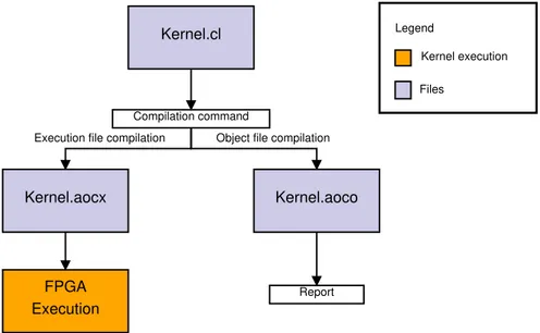
The OpenCL framework for FPGAs allows the designer to simply create an appli-cation by means of High-Level Design (HLD) approach. For this work, the Intel FPGA SDK for OpenCL is considered and it supports the OpenCL specification 2.0 [HM15]. The Intel FPGA SDK for OpenCL Offline Compiler compiles the kernels to an image file used by the host to program and run the kernel on the FPGA. The model previously described remains the same with an important difference: the FPGA exploits spatial implementation of a program, thus the
Chapter 3 - Reconfigurable computing for 5G RAN acceleration
instructions are executed when the data are ready. However, in sequential pro-gramming (considered for CPU, GPGPU, DSP), the program counter controls the instructions to run. Even if the data are available to be computed, the pro-cessing is executed one instruction at a time, following the order of the program counter. This method is time-dependent since the instructions are executed on the hardware across time. Designers have to take into account this crucial differ-ence to create an application FPGA-oriented. Indeed, the way the code is written permits to avoid FPGA area overhead or performance degradation.
Kernel.cl Compilation command Report Kernel.aoco Kernel.aocx FPGA Execution Kernel execution Files Legend
Object file compilation Execution file compilation
Figure 3.3. Intel FPGA SDK for OpenCL workflow
Figure 3.3 shows the Intel FPGA SDK for OpenCL kernel compilation flow. The Intel FPGA SDK for OpenCL Offline Compiler compiles the kernel and it creates the hardware configuration in a single step (i.e., kernel.aocx). An intermediate step, that creates an OpenCL object file (i.e., kernel.aoco), provides the report on area usage and performance bottlenecks, especially in the memory access. Two types of kernels are supported by the OpenCL for FPGA framework: ND-Range and Single Work-Item (SWI) kernels. A NDND-Range kernel permits to parti-tion the data among the PEs. In particular, the OpenCL runtime system creates an integer index space (i.e., NDRange) where each instance of the kernel is ex-ecuted. Each instance is called work-item and it is identified by its coordinates in the NDRange. This kernel is suitable when there is no data dependency that makes the partitioning easy. The commands run from the host to create the
Section 1 - Acceleration with Reconfigurable Hardware through OpenCL
collection of the work-items and execute all the work-items in parallel. Work-items are organized in structures called work-groups and each work-group has an unique ID, thus the single work-item can be identified through its global ID or by a combination of work-group ID and local ID (assigned to the work-item within the work-group). To understand how the IDs are mapped, we consider a 2D NDRange. A lowercase g letter refers to the global ID of a work-item, thus the coordinates (gx, gy) uniquely identify a work-item in the space. Instead, the
uppercase G letter is related to the size of the space in each directions. The NDRange space can be written as [0 .. (Gx - 1), 0 .. (Gy - 1)]. Then, we divide
the NDRange in work-groups with the same conventions described: Wx-by-Wy
represents the NDRange space expressed in the work-group space while the coor-dinates (wx, wy) refer to the work-item inside the work-group. The dimensions Lx
and Ly of each work-group can be calculated with the equations Eq.2 and Eq.3:
Lx = Gx Wx (2) Ly = Gy Wy (3)
We explained that a work-item is identified by its global ID (gx, gy) or by the
combination of its local ID (lx, ly) and work-group ID (wx, wy). Hence, Eq.4 and
Eq.5 show the relationship between IDs.
gx = wx∗ Lx+ lx (4)
gy = wy∗ Ly + ly (5)
Figure 3.4 reports an example where global IDs, local IDs, and work-group in-dices are depicted in a 2D NDRange space [MGMG11]. The memory model for the NDRange kernel remains the same depicted in Figure 3.2.
Executing NDRange kernels with size (1,1,1) (or with one work-group that con-tains one work-item) corresponds to run a SWI kernel. SWI kernels permit to control the pipeline since only one work-item is executed. This approach is bet-ter when an application has loops or data dependencies. The NDRange tries to parallelize the computation with several work-items but the performance could be degraded due to a possible stalls for conflicts with data. Unlike NDRange kernels, single work-item kernels follow sequential programming approach, more similar to C programming. Anyway, the data parallelism is applied on SWI ker-nel type by pipelining the iterations of loops. Indeed, custom pipeline is possible
Chapter 3 - Reconfigurable computing for 5G RAN acceleration
Figure 3.4. 2D example of mapping global IDs, local IDs, and work-group indices in NDRange
and data access patterns can be modified using ad-hoc ”pragmas”. More details about the improvements of these kernels in terms of area usage and processing time are described in the next section.
2. Insights on OpenCL kernel optimization for FPGA
The main advantage of OpenCL model is certainly the portability, since the same code can be compiled for different architecture. Moreover, its easy integration with the software enables the possibility of the parallel and sequential processing integration. Unfortunately, each architecture requires its optimization since spe-cific instructions have to be executed to achieve better performance. For instance, the SWI kernel can run in the GPGPU but with very low throughput [WS15]. Indeed, the GPGPU is equipped with thousands of cores, each capable to run a single work-item, thus a NDRange kernel is more suitable for this platform. Hence, the platform optimization is an important process before compiling an
Section 2 - Insights on OpenCL kernel optimization for FPGA PE 0 PE 1 PE N 0 1 7 6 5 4 3 2 ... N 0 1 7 6 5 4 3 2 ... N a b Load a[0] Load b[0] Load a[1] Load b[1] Load a[N] Load b[N] + + + Store c[0] Store c[1] Store c[N] 0 1 7 6 5 4 3 2 ... N c
Figure 3.5. Data parallelization of NDRange kernels
OpenCL application and bad optimizations may lead to a platform inefficiency for OpenCL kernels. This section addresses the optimization to be taken into account for OpenCL FPGA SWI and NDRange kernels. A more exhaustive deepening is considered for SWI kernels since the application used as use case is SWI-based.
2.1. OpenCL NDRange kernel optimization. To understand how ND-Range kernels are mapped into the FPGAs, we consider the code in Figure 3.6. This kernel permits to do the sum of each element of a with each element of b. OpenCL runtime spreads the sum operations among all the PEs, thus each PE has the role to add one element of a with one element of b, as depicted in Figure 3.5. To avoid area overhead, it is necessary to specify the maximum dimension of the work-group. In this way, the compiler is able to precisely map the kernel to the hardware resources.
Kernel vectorization permits to improve the throughput since multiple work-items can be executed in a single PEs, exploiting the SIMD instructions. N-sized vectorization can increase the throughput up to N times (where N can be 2, 4, 8 or 16). N sum operations can be mapped to a single PE without modifying the kernel structure. Here, each PE can handle N operations and the NDRange dimension can be decreased to save area usage.
Chapter 3 - Reconfigurable computing for 5G RAN acceleration
This method spreads the kernel processing among the compute units and the compiler handles each compute unit as a unique pipeline. Considering T as pro-cessing time to complete the kernel execution without multiple compute units and N as the number of compute units, the processing time with multiple compute units is NT. This method increases the area usage as well as the global memory bandwidth which could be higher than the physical interface throughput of the global memory itself (e.g., DDR interface if the global memory is a Random Ac-cess Memory (RAM)). In this scenario, the performance could be worse due to a delay of global memory accesses.
Both kernel vectorization and multiple compute units can be instantiated to achieve higher efficiency, but kernel vectorization is preferable over the multiple compute units. Indeed, multiple compute units increase the number of accesses to the global memory while the SIMD vectorization changes the amount of work that a single PE has to handle. Exploiting the SIMD vectorization, no undesired memory accesses are possible and the performance are the same offered by the instantiation of multiple compute units.
__kernel void sum (
__global const float * restrict a,
__global const float * restrict b,
__global float * restrict answer
) {
size_t gid = get_global_id(0); answer[gid] = a[gid] + b[gid]; }
Figure 3.6. NDRange kernel to add two vectors
2.2. OpenCL SWI kernel optimization. An OpenCL application based on SWI kernel would be preferable to NDRange kernels in FPGA due to possible conflicts in the memory accesses. Indeed, as described above, NDRange kernels are spreaded among all the PEs that have concurrent accesses to the memory, thus a data dependency can create stalls that decrease the performance. However, SWI kernels permit to control the whole pipeline, as well as the memory accesses. Figure 3.8 shows the same OpenCL code of Figure 3.6 adjusted to be a SWI kernel
Section 2 - Insights on OpenCL kernel optimization for FPGA
+ For loop entry
For loop end Load b[i] Load a[i]
Store c[i]
Figure 3.7. SWI kernel pipeline
and, in Figure 3.7, the pipeline of the SWI kernel is depicted. The different approach compared to the NDRange kernel is clear: SWI kernel are based on pipelines that can be controlled and customized while NDRange model is based on massive data parallelization. Both NDRange and SWI kernel include the restrict keyword in the kernel pointer arguments. Including this keyword, the compiler is prevented to create unnecessary memory dependencies and it avoids conflicts on memory accesses.
SWI kernel are loop-based, thus it is possible to achieve the best performance by avoiding data dependency on the pipeline and concurrent memory accesses. These conditions are fundamental to optimize a SWI kernel, otherwise the OpenCL compiler needs too much FPGA area to efficiently address data dependency (i.e., implementation of multiple instances of the same variable). A loop inside a SWI kernel can be unrolled, which means that the system tries to run each loop iter-ation in parallel. Hence, by means of #pragma unroll N directive, the compiler unrolls the loop N times. This reflects on a speed up of N times in the execution performance of the loop (without specify the N factor, the compiler automati-cally unrolls the whole loop). Unrolling read and write loops of global memory access enables to achieve the compile-time memory coalescing. This approach is typical when a uniform and regular memory access is needed. In particular, an irregular or not aligned access to the memory tends to decrease the performance in FPGA. The memory transfer between the host and the global memory has
Chapter 3 - Reconfigurable computing for 5G RAN acceleration
to be aligned to exploit the Direct Memory Access (DMA) acceleration. Un-rolling global memory loops permits to have an efficient access, exploiting the whole communication bandwidth of the memory. On the other hand, choosing a big values of N corresponds to have accesses larger than the external memory bandwidth, thus the best unrolled factor is the one that saturates the memory bandwidth.
A significant optimization on area usage is to avoid function calls in the SWI kernel. Indeed, every function call is implemented as a circuit on the FPGA, resulting in a large usage of FPGA resource. Moreover, functions calls prevent the compiler to create a correct report about FPGA area usage that makes the debug harder.
Writing OpenCL code for hardware-oriented programming leads to an improve-ment in terms of performance and area usage. As matter of example, we can consider a simple if-then-else directive implemented in both software and hard-ware. In software sequential programming, the if-then-else statement presents an issue in the pipeline. Indeed, there are two possible instructions to be fetched and the CPU has to take a decision based on the condition. Modern CPUs attempt to predict the correct instruction to be executed. Then, the processor fetches the in-structions based on such a prediction and, in case of wrong prediction, it discards the partially executed instructions in the pipeline. In this scenario, the pipeline is not stalled, ensuring a smooth execution of the directives. However, in hardware approach (i.e., spatial programming), both ”if” and ”else” instructions branches are mapped into hardware circuits which lead to a FPGA area overhead since only one circuit is considered at a time. Using conditional statements (i.e., out = (condition) ? in 1 : in 2) instead of if-then-else statements can reduce the FPGA resources in many cases. Indeed, the if-then-else construct follows the sequential approach and infers a priority routing network, which needs higher resources. However, conditional statements are mapped as a unique MUX circuit in hardware and they yields better results in terms of both resource saving and performance [ ¨ORHT16].
Section 3 - Related works on OpenCL hardware acceleration
__kernel void sum (
__global const float * restrict a,
__global const float * restrict b,
__global float * restrict answer,
int N )
{
for (int i = 0; i < N; i++)
answer[i] = a[i] + b[i]; }
Figure 3.8. SWI kernel to add two vectors
3. Related works on OpenCL hardware acceleration
To the best of our knowledge, this study is the first that considers OpenCL ac-celeration in the context of 5G. A number of recent works rely on the OpenCL language for FPGAs to deploy advanced services such as Convolutional Neural Networks (CNNs), Finite Impulsive Response (FIR) filters or image processing accelerations. In [WTS18], the authors provide an exhaustive analysis about the Time-Domain Finite Impulsive Responses (TDFIRss) and Frequency-Domain Finite Impulsive Responses (FDFIRss) implemented in the FPGA by means of OpenCL. In particular, they focus on the performance of several FIR implemen-tations on the FPGA as well as performance comparison between FPGA and GPGPU. Moreover, an analysis on the area usage and power consumption is reported.
An optimized implementation of a CNN is proposed in [AOC+17], where the
au-thors consider Deep Learning Accelerator (DLA) to overcome the memory bound limit of the CNN deployment into FPGA. They maximize the data reuse and minimize external memory bandwidth. Moreover, Winograd transform is further applied to boost the FPGA performance. The results of such a scenario show that the system is 10x faster of the state-of-the-art implementation and it has comparable performance with GPGPU CNN deployment.
Another approach to improve CNN computation on the FPGA is described in [ZL17]. Here, an analytical performance model regarding area usage is pre-sented and applied to a CNN implementation. Authors show a bottleneck on