UNIVERSITÀ DEGLI STUDI DI NAPOLI “FEDERICO II”
Scuola Politecnica e delle Scienze di Base
Department of Industrial Engineering – Aerospace Division
Doctoral Programme in Industrial Engineering
XXXI Cycle
Aeroelastic stability assessment of a CS-25 category aircraft
equipped with multi-modal wing morphing devices
Supervisors
Prof. Eng. Francesco Marulo
PhD Candidate
Prof. Eng. Leonardo Lecce Maria Chiara Noviello Prof. Eng. Rosario Pecora
Prof. Eng. Francesco Amoroso
Co-supervisors
PhD Antonio Concilio PhD Ignazio Dimino
3
Dediche
A mio marito Domenico e alla mia preziosa famiglia, per essere la certezza più forte ed incrollabile che possa esistere. Nulla di tutto questo sarebbe stato possi-bile senza la vostra costante presenza, dolce rifugio per me.
Alle mie speciali Amisisters, perché la distanza “spaziale” non ci ha mai impedito di essere quotidianamente vicine. Grazie per i nostri “Ci amo”, per le parole di conforto e di confronto e per i “A domani, bimbe”, come promessa che ci saremo sempre l’una per l’altra. This is the Amisisters’ power!
4
Acknowledgments
First and foremost, I would like to thank the PhD School of the University of Naples “Federico II” for giving me the opportunity to work on this interesting research.
I wish to express my gratitude to Professor Leonardo Lecce for being an example of “war machine” to follow.
Many thanks to my Professor Rosario Pecora for passing on strong passion and enthusiasm for work to his students and… enthusiasm is contagious! I am ex-tremely grateful for the technical assistance, patient supervision and excellent guidance provided throughout my PhD.
I wish to thank my Professor Francesco Amoroso for being by my side during these years. Constructive criticism during the discussion sections brought me to grow and mature. Besides, I am very grateful for the empathy, humility and lis-tening, rare gifts.
…This is why they are “Two Number One Professors”!
…And, last but not least, I want to thank the Italian Aerospace Research Center for giving me this opportunity of professional growth, and for contributing to the stimulating and exciting atmosphere in which I was able to conclude my studies. I had the privilege of receiving authoritative scientific opinions of PhD Antonio Concilio and to work under the invaluable supervision of PhD Ignazio Dimino, whose teachings were fundamental to reach this goal.
5
Abstract
Morphing wing structures have the greatest ambition to dramatically improve aircraft aerodynamic performance (less fuel consumption) and reduce aerody-namic noise. Several studies in the literature have shown their potential for in-creased aerodynamic efficiency across nearly all flight conditions, enhanced air-craft maneuverability and control effectiveness, decreased takeoff/landing length, reduced airframe noise, etc. However, despite a long heritage of research, morphing wing technology has yet to be approved by the European Aviation Safety Authority (EASA) for use in commercial aviation. Models and approaches capable to predict the aeroelastic impact of a morphing wing still need to be ma-tured to safely alter design and operation of future generations of aircraft. Addi-tionally, a number of practical challenges remain to be addressed in the suitable materials, systems reliability, safety and maintenance.
Due to the reduced stiffness, increased mass and increased Degree Of Free-dom (DOF) with respect to conventional wings, these mechanical systems can cause significant reduction of aircraft flutter margins. This aspect requires dedi-cated aeroelastic assessments since the early stages of the design process of such an innovative wing. Flutter boundaries predictions need sensitivity analyses to evaluate bending/torsional stiffness and inertial distribution variability ranges of the aircraft wing equipped with the morphing wing devices. In such a way, aero-elastic assessments become fundamental to drive a balance between weight and stiffness of the investigated adaptive systems. Furthermore, in pseudo rigid-body mechanisms-based morphing structures, the inner kinematics is so important that its faults may compromise the general aircraft-level functions. Similarly to the demonstration means of safety compliance, commonly applied to aircraft control surfaces, the novel functions resulting from the integration of adaptive devices into flying aircraft thus impose a detailed examination of the associated risks.
In the framework of Clean Sky 2 Airgreen 2 project, the author provides ad-vanced aeroelastic assessments of two adaptive devices enabling the camber morphing of winglets and flaps, conceived for regional aircraft integration (EASA CS-25 category). Segmented ribs architectures ensure the transition from the baseline (or un-morphed) shape to the morphed ones, driven by embedded electromechanical actuators. Some of the advantages resulting from the combi-nation of the two aforementioned morphing systems are wing load control, lift-over-drag ratio increase and root bending moment alleviation.
6
The aircraft aeroelastic model was generated by means of the proprietary code SANDY 3.0 (see APPENDIX A – General Description of the Sandy code). Then, the same code was adopted to solve the aeroelastic stability equations through theoretical modes association in frequency domain. To carry out multi-parametric flutter analyses (P-K continuation method), the actuation lines stiff-ness and winglet/flap tabs inertial parameters were considered in combination each other. Nominal operative conditions as well as systems malfunctioning or failures were examined as analyses cases of the investigated morphing devices, together with actuators free-play conditions. Proper design solutions were sug-gested to guarantee flutter clearance in accordance with aircraft stability robust-ness with respect to morphing systems integration, evaluated through a combina-tion of “worst cases” simulating the mutual interaccombina-tion among the adaptive sys-tems.
The safety-driven design of the morphing wing devices required also a thor-ough examination of the potential hazards resulting from operational faults in-volving either the actuation chain, such as jamming, or the external interfaces, such as loss of power supplies and control lanes, and both. The main goal was to verify whether the morphing flap and winglet systems could comply with the standard civil flight safety regulations and airworthiness requirements (EASA CS25). More in detail, a comprehensive study of systems functions was firstly qualitatively performed at both subsystem and aircraft levels to identify potential design faults, maintenance and crew faults, as well as external environment risks. The severity of the hazard effects was thus determined and then ranked in specific classes, indicative of the maximum tolerable probability of occurrence for a spe-cific event, resulting in safety design objectives. Fault trees were finally produced to assess the compliance of the system architectures to the quantitative safety requirements resulting from the FHAs.
7
Index
1 Introduction ... 15 1.1 General ... 15 1.2 Motivation of work ... 18 1.3 Objectives ... 201.4 Organization of the thesis ... 21
1.5 Author’s published works ... 22
2 State of the art on morphing structures ... 25
2.1 Adaptive wings ... 25
2.2 Clean Sky 2 Airgreen 2 Project ... 29
2.3 Overview on AG2 morphing devices ... 30
3 Morphing wing devices ... 33
3.1 Morphing flap ... 33
3.1.1 Scope and reference geometries ... 33
3.1.2 Aerodynamics and Benefits ... 34
3.1.3 Morphing flap architecture ... 36
3.2 Morphing winglet ... 40
3.2.1 Scope and reference geometries ... 40
3.2.2 Aerodynamics and Benefits ... 41
3.2.3 Morphing winglet architecture ... 42
4 Aeroelasticity ... 45
4.1 Introduction ... 45
4.1.1 Structural Model ... 45
4.1.2 Inertial Model ... 46
4.1.3 Aerodynamic Model ... 46
4.2 Aeroelastic stability equations ... 46
4.2.1 Generalized Aerodynamic Forces ... 46
4.2.2 Impedance matrix ... 48
4.3 Classification of the methods for flutter evaluation ... 50
8
4.3.2 PK methods ... 54
4.4 Aerodynamic forces approximation ... 58
4.4.1 P method ... 59
4.5 Harmonic Balance Method ... 61
5 Aeroelasticity of morphing devices ... 65
5.1 Dynamic Model ... 65
5.1.1 Structural Model ... 65
5.1.2 Inertial Model ... 73
5.2 Aerodynamic and Interpolation Model ... 74
5.3 Flutter Analyses ... 75
5.3.1 Trade-off flutter analysis on flap tabs ... 76
5.3.2 Trade-off flutter analysis on winglet tabs combined with flap tabs 86 5.3.3 Free-Play Analyses Results, Harmonic Balance Method ... 103
6 Morphing Wing – Safety and Reliability issues ... 106
6.1 Introduction ... 106
6.2 Safety Analysis: general approach ... 107
6.2.1 Functional Hazard Assessment - FHA ... 111
6.2.2 System Safety Assessment—Fault Tree Analysis ... 113
6.2.3 Active Versus Hidden Failures ... 114
6.2.4 On safety factor ... 115
6.3 Morphing devices: Aircraft level functions ... 115
6.4 Morphing flap ... 117
6.5 Morphing winglet ... 122
6.6 Integrated Safety Analyses ... 128
7 Conclusions and Future Works ... 136
APPENDIX A – General Description of the Sandy code ... 138
APPENDIX B - CS 23.629 Flutter ... 140
9
Nomenclature
1D Mono-Dimensional
2D Bi-Dimensional
2MMF Bi-Modal Morphing Flap
3D Three-Dimensional
3MMF Three-Modal Morphing Flap
A/C Aircraft
AIC Aerodynamic Influence Coefficients
b Span Length
Bi i-th Block Of The Rib
CL Lift Coefficient
CL_MAX Maximum Lift Coefficient
CP Pressure Coefficient
Cr Root Chord Length
Ct Tip Chord Length
D Drag
DLM Doublet Lattice Method
DMIG Direct Matrix Input At Grids
DOF Degree Of Freedom
EA Normal Force Stiffness
ECU Electronic Control Unit
EImin(max) Minimum (Maximum) Bending Stiffness FDAL Functional Design Assurance Level
FE(M) Finite Element (Model)
FHA Fault And Hazard Assessment
FT(A) Fault Tree (Analysis)
GAF Generalized Aerodynamic Forces
Gij Participation Factor Mode I With Respect To Mode J
GJ Torsional Stiffness
GRA Green Regional Aircraft
GVT Ground Vibration Test
HD Harmonic Drive
K Actuators Stiffness
Keq Actuators Equivalent Stiffness L/D Aerodynamic Efficiency
L Lift
LVDT Linear Variable Displacement Transducer
MAC Mean Aerodynamic Chord
MAV Micro Air Vehicle
MT Maintenance Time
MWL Morphing Winglet
MZFW Maximum Zero Fuel Weight
NS Navier-Stokes
PSSA Preliminary System Safety Assessment
RBE Rigid Body Element
SSA System Safety Assessment
10
TRL Technology Readiness Level
UAV Unmanned Aircraft Vehicle
VD Dive Speed
11
List of Figures
Fig. 1: Example of flutter shapes in case of movable surfaces ... 17
Fig. 2: Wright-Brothers aircraft: a detail of wing warping, [19] ... 25
Fig. 3: Morphing wing concept: (a) NASA Dryden inflatable wing during flight testing [24]; and (b) telescopic wing concept [25] ... 27
Fig. 4: (a) Lockheed Martin folding-wing UAV concept, [26], and (b) NextGen Batwing morphing UAV concept, [27] ... 27
Fig. 5: MAV roll control achieved via wing warping, [28] ... 28
Fig. 6: Drooped Nose structure, [30] ... 31
Fig. 7: Morphing flap architecture, top view ... 32
Fig. 8: Morphing winglet Finite Element Model (left) and architecture (right), [31] ... 32
Fig. 9: Morphing flap investigation domain, [32] ... 34
Fig. 10: Aerodynamic pressure uniform distribution on tabs surfaces, [32] ... 35
Fig. 11: Morphing flap articulated rib, [32] ... 36
Fig. 12: Morphing flap target shape, mode 1, [32] ... 36
Fig. 13:B1/B2 gear ratio trend, [32] ... 37
Fig. 14: Morphing flap preliminary design assumption, [32] ... 38
Fig. 15: Section view of through shaft actuation concept, [32] ... 39
Fig. 16: Wireframe view of through shaft actuation concept, [32] ... 39
Fig. 17: Movable surfaces of the morphing winglet, [38] ... 40
Fig. 18: Upper (on left) and lower (right) deflection, [38] ... 41
Fig. 19: Example of Cp distribution on the morphing winglet for negative deflections of both the upper and lower surfaces, [38] ... 41
Fig. 20: Detail of the morphing winglet architecture, [38]. ... 42
Fig. 21: Detail of the morphing winglet architecture, [38]. ... 43
Fig. 21: EMA actuators: a) sectional and b) external view, [37] ... 43
Fig. 22: Aeroelasticity conceptual scheme, [40] ... 45
Fig. 23: Aerodynamic Lattice, [40] ... 47
Fig. 24: Example of V-g plot in case of two modes only, K-Method, [40] ... 52
Fig. 25: Non –linearity in a linear system, [40] ... 61
Fig. 26: LH morphing flap preliminary Finite Element Model developed by UniNa, [31] ... 66
Fig. 27: LH morphing winglet preliminary Finite Element Model developed by CIRA, [31] ... 66
Fig. 28: Elastic axis convergence parameter, [31] ... 68
Fig. 29: Logical Flow for the stiffness properties evaluation ... 69
Fig. 30: Example of load case applied for GJ evaluation, [31] ... 70
Fig. 31: Flap tabs stiffness properties ... 71
Fig. 32: Winglet tabs stiffness properties ... 72
Fig. 33: TP90 Dynamic model in Sandy environment (ref. axes in meters), [31] ... 74
12
Fig. 34:TP90 aerodynamic model in Sandy environment (ref. axes in meters),
[31] ... 74
Fig. 35: TP90 Aeroelastic model in Sandy Environment (ref. axes in meters), [31] ... 75
Fig. 36: Trade- off analyses parameters on flap tabs ... 77
Fig. 37: First trade-off Carpet Plot ... 77
Fig. 38: Flutter mode 31 - Symmetric wing tip/winglet bending ... 78
Fig. 39: Flutter Mode 37 - Symmetric outer wing torsion ... 79
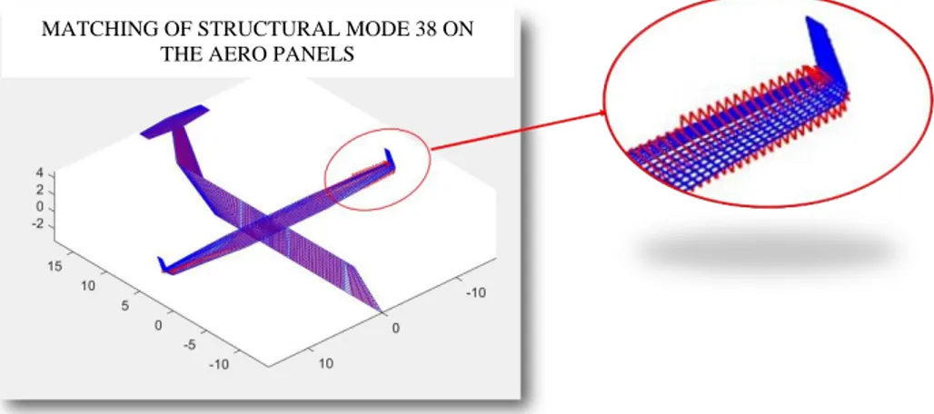
Fig. 40: Flutter Mode 38 - Anti-symmetric outer wing torsion ... 79
Fig. 41: Participation Factors, Mode 31 [31] ... 80
Fig. 42: Participation factors, Mode 37, [31] ... 81
Fig. 43: Participation factors, Mode 38, [31] ... 81
Fig. 44: Minimum modal flutter association ... 82
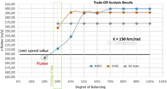
Fig. 45: Minimum flutter speed as function of flap tabs degree of balancing, for a fixed value of tabs actuation line stiffness ... 84
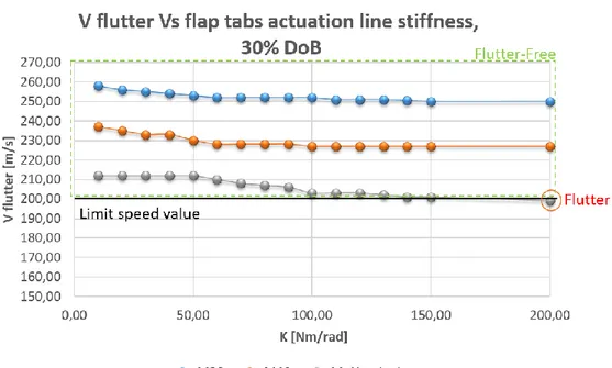
Fig. 46: Minimum flutter speed as function of flap tabs actuation line stiffness, 30 % Degree of Balancing ... 85
Fig. 47: Flutter speed as function of tabs actuation line stiffness, 40% Degree of Balancing ... 85
Fig. 48: Trade-off analysis on winglet tabs combined with flap tabs in locked commands, carpet plot [31] ... 87
Fig. 49: Mode 31: anti-symmetric wing tip torsion/winglet bending ... 88
Fig. 50: Mode 32: Symmetric outer wing torsion/winglet bending ... 88
Fig. 51: Anti-symmetric outer wing torsion/winglet bending ... 89
Fig. 52: Example of V-g plot on winglets tabs trade-off analysis, [31] ... 90
Fig. 53: Mode 31, Participation factors ... 91
Fig. 54: Mode 32, Participation factors ... 91
Fig. 55: M33, Participation factors ... 91
Fig. 56: Minimum modal association, winglets tabs flutter modes ... 92
Fig. 57: Minimum flutter speed VS winglet tabs degree of balancing in two inertial configurations (nominal and 30% increase of the nominal mass) ... 93
Fig. 58: Minimum flutter speed as function of tabs degree of balancing. ... 94
Fig. 59: Flutter speed trend as a function of plug stiffness gain factor ... 95
Fig. 60: Flutter speed trend as a function of tabs massbalancing, F DMIK = 5 96 Fig. 61: Winglets tabs mass gain factor as function of flutter speed, with plug stiffness gain factor equal to 5 ... 97
Fig. 62: Winglets tabs mass gain factor as function of flutter speed, with plug stiffness gain factor equal to 2 ... 97
Fig. 63: Winglet bending mode (M32), in case of no plug stiffness gain factor and 100% tabs mass ... 99
Fig. 64: V-g plot in the condition A ... 100
Fig. 65: – Simmetric wing torsional-bending mode in case of F DMIK=2 and wlet tabs mass 70% ... 101
13
Fig. 67: Load-Deflection non-linear law ... 103
Fig. 68: Winglet tabs actuators equivalent stiffness Vs tabs oscillation amplitude ... 104
Fig. 69: Flutter analyses results in case of tabs actuators free-play ... 105
Fig. 70: Example of electromechanical Actuator fault tree with failure rates per hour ... 107
Fig. 71: CS-25 safety assessment process overview ... 109
Fig. 72: Relationship between Probability and Severity of Failure Condition Effects, [2] ... 110
Fig. 73: Required probability figures versus safety classification ... 113
Fig. 74: Safety factor vs probability in failure condition ... 115
Fig. 75: Morphing Flap High Lift Generation Fault Tree Analysis ... 121
Fig. 76: Morphing flap Undetected Inadvertent tab control at high speed Fault Tree Analysis ... 121
Fig. 77: Morphing winglet - Uncontrolled dynamic motion (left or right) Fault Tree Analysis ... 127
Fig. 78: Destruction of wing FTA ... 127
Fig. 79: LH winglet tabs actuators and gear ratio DMIG scheme, Baseline configuration ... 128
Fig. 80: CASE 1 – LH upper link isolated failure ... 129
Fig. 81: CASE 2 – LH lower link isolated failure ... 130
Fig. 82: CASE 3: LH upper tab actuator isolated failure ... 130
Fig. 83: CASE 4 - LH lower tab actuator isolated failure ... 131
Fig. 84: CASE 5 – LH upper actuator and link combined failure ... 132
Fig. 85: CASE 6 – LH lower actuator and link combined failure ... 132
Fig. 86: CASE 7 – LH upper actuator and lower link combined failure ... 133
Fig. 87: CASE 8 – LH lower tab and upper link combined failure ... 134
14
List of Tables
Table 1: Aerodynamic values in limit load condition, [32] ... 35
Table 2: Winglet materials mechanical properties ... 44
Table 3: Massbalancing values of morphing flap tabs ... 83
Table 4: Massbalancing solutions: impact on winglet weight ... 86
Table 5: Winglet weight in case of 130% DoB ... 94
Table 6: Winglet weight in case of doublet stiffness of plug and 30% saving of tabs mass ... 98
Table 7: Flutter Results of Condition A ... 98
Table 8: Flutter Results of Condition B ... 100
Table 9: Equivalent stiffness of winglet tabs actuation line ... 104
Table 10: Aircraft functions impacted by Morphing Wing concept, [43]-[44]116 Table 11: Aircraft functions impacted by Morphing Flap concept, [45] ... 119
Table 12: Potential failures identified in morphing winglet preliminary FHA ... 123
Table 13: Aircraft functions impacted by Morphing Winglet concept ... 125
Table 14: Failure scenarios investigated for morphing winglet ... 129
Table 15: Flutter analyses results in failure scenarios investigated for morphing winglet ... 134
15
1 Introduction
1.1 General
Over the last few years, aerospace research efforts are increasingly focusing on advanced solutions capable to improve aerodynamic efficiency for reducing fuel consumption and pollutant emissions of the next generation air transport. One of the ways to accomplish such benefits relies on morphing wing devices, capable of adapting their shape in a continuous manner during aircraft flight. From the structural perspective, this requires developing fully integrated struc-tures with actuation and compliance control capable to fulfill conflicting require-ments: the structure must be stiff to withstand the external loads, but must be flexible to enable shape changes.
There is no doubt that the achievement of adaptive structures entails more complex and heavier architectures, if compared to conventional ones, to with-stand operative loads with adequate margins of safety. This aspect is predictable and manageable since the price to be paid for a technology implementation at aircraft level is proportioned to the benefits brought by it. Moreover, assuming the civil transportation as a target, also the smallest improvement becomes sig-nificant when multiplied by the massive amount of aircraft composing the fleet. It was demonstrated that by means of the adaptive wing trailing edge camber morphing, the aerodynamic efficiency increases by 2%; as a consequence, fuel burnt saving was estimated equal to the 3% per flight, [1]. These numbers give us the immediate perception of the environmental benefits; beyond that, such a decrease in fuel burnt allows for a strong operative cost saving (about 10 million dollars/year for a mid-size fleet of large commercial airplanes). Therefore, for larger fleets there are bigger advantages. Nevertheless, although morphing de-vices generally have favorable performance for small or unmanned aircraft ap-plications, the most ambitious challenge is to explore true-scale solutions for manned flights, compliant with EASA (/FAA) airworthiness requirements part 25 ([2]) and with series production and implementation on modern civil aircraft. The associated technological development required for such aircraft segment is very high. However, it is also true that the payoff may be, in perspective, very high.
When dealing with the design of morphing wing devices, multidisciplinary aspects need to be thoroughly considered due to the systems complexity involv-ing aerodynamics, structures, actuation architectures, control logics and aeroe-lasticity, [3].
16
Speaking about the latter, it regards the effect of aerodynamic forces on elas-tic bodies, such as aircraft wings or compressor blades, which fully depend on the deformed shape of the structure in the flow. One of the most serious aeroe-lastic phenomena is the instability of a structure in a flow. For a given initial shape of an elastic structure, the aerodynamic force increases rapidly with the flow speed, and there may exist a critical flow speed at which the structure be-comes unstable. Such instability may cause excessive deformation, and may lead to the destruction of the structure. The interplay of aerodynamic, elastic, and in-ertia forces is usually referred to as flutter or dynamic aeroelastic instability. If a structure is excited with external forces in the absence of flow, the structure will oscillate and the oscillation will damp gradually. With the presence of a flow, the rate of damping of the oscillation may increase at low flow speeds and on in-creasing the flow speed, a point will be reached at which the damping rapidly decreases, and the oscillation can just maintain itself with a steady amplitude. This speed is known as the critical flutter speed, and at speed of flow just above that critical speed, a great violent oscillation will be triggered, at any small dis-turbance to the structure, and the structure is said to flutter.
There are many definitions of flutter within the literature. Some of the most recognized are [4] – [5]:
• Aeroelastic and self-excited vibration, in which the external source of energy is the air stream;
• Aerodynamic self-exited oscillations; • Self-sustained oscillatory instability;
• Cyclic and high frequency oscillation of the airfoil caused by a strug-gle between the aerodynamic forces and the stiffness of the surfaces; • Dynamic instability of an elastic body in an airstream produced by aerodynamic forces which result from the deflection of the elastic body from its undeformed state;
• Dynamic aeroelastic instability;
• Dynamic instability occurring in an aircraft in flight at a certain speed where the elasticity of the structure plays an essential part in the in-stability;
• Self-excited or unstable oscillation arising out of the simultaneous action of elastic, inertia and aerodynamic lift forces upon a mass or a system of masses;
17
• Oscillatory instability arising from the condition where one degree of freedom is driven at resonance by a second degree of freedom, both oscillating at the same frequency;
• Unstable divergent motion or vibration caused by the aerodynamic forces;
• A condition at which the total damping of a system under the action of air forces (and the inertia, elastic, and friction forces) changes from positive to negative, at flutter speed the damping is zero so that sus-tained oscillations would occur.
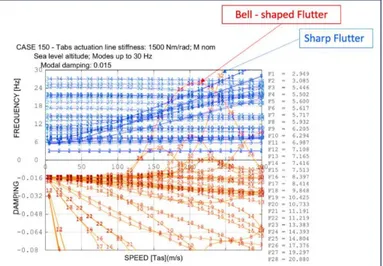
The parametric study of flutter is a crucial step of the aeroelastic assessment. Aeroelastic stability equations can be solved numerically by adopting different methods, detailed in Section 4. Typically, the outputs of flutter analyses are con-densed in the so-called V-g plot, showing the trend of flutter modes speed as a function of the modal damping (further details are provided in APPENDIX B - CS 23.629 Flutter).
When dealing with conventional A/C movable surfaces (flaps, ailerons, rud-der…), both bell-shaped and sharp flutter instabilities may occur, as shown in Fig. 1. Due to the unconventional arrangement of morphing systems and their
mutual interaction in a morphing wing, especially in systems malfunctioning
or failure conditions, such aeroelastic assessments are strongly recommended since the preliminary stage of the wing design process. In what follows, the aero-elastic behavior of a regional aircraft wing equipped with morphing flaps and adaptive winglets is investigated to estimate design feasibility and effectiveness from a structural standpoint.
18
1.2 Motivation of work
In general, morphing structures can change their geometry in order to achieve a wide range of performance, [6]. In case of morphing aircraft, such goals include alleviating drag, or altering airfoil lift.
Conventional engineered structures, such as aircraft wings, are conceived to exhibit a desired aeroelastic response. This allows for obtaining small operational deflections, and hence well-defined aerodynamic and aeroelastic loading. There-fore, structural engineers feel certain that a wing with the required mass and stiff-ness, and with the shape set out by aerodynamics engineers, will allow achieving the predicted lift and drag properties. Well-developed aircraft systems sizing methods apply, speeding up the early stages of the design process, [7]. It is not possible to state the same for the design of morphing wing structures. The large changes in performance achievable have an inevitable impact in terms of the mass, stiffness and actuation requirements. This complicates the systems sizing, since it is not immediate defining which morphing configuration should dominate the design. In the literature, these difficulties are overcome by reducing the prob-lem to its constituent components. These involve designing the aircraft structure ensuring the target morphing shapes, or performing aerodynamic optimization to find the optimum shapes that wings should morph between. A further step regards the interaction between structure and aerodynamics, to ensure aeroelastic stabil-ity during flight. The strategy of splitting the design problem into distinct disci-plines has enabled production of a great amount of morphing aircraft concepts. However, it should be noted that a more comprehensive approach could empha-size the potential structural improvements in terms of weight and number of com-ponents while maintaining the requested aerodynamic benefits. A brief summary of these design methods is recalled below to highlight the difficulties of an inte-grated-design approach.
• Structural optimization solves a material distribution problem sub-ject to constraints, [8]. For the majority of structural optimization problems, the aim is to conceive a structure which can support a given load, although achieving other characteristics as, for example, minimum total weight, optimal center of mass location, or meeting a given density requirement. Typically, the optimization problem is solved through parametrization schemes, such as sizing, material, shape and topology optimization [9] - [10] - [11] - [12].
19
• Aerodynamic optimization is the process of finding the geometry providing the best aerodynamic properties. A typical problem opti-mizes a set of decision variables governing the airfoil shape through a predefined parameterization scheme. The new shape’s aerody-namic properties are then evaluated, and used to update the decision variables, until the geometry has converged to an optimal solution [13] - [14] - [15]. Aerodynamic optimization of morphing structures requires replacement of the shape parameterization by a structural model with optimizer-controlled actuation, [16]. The sensitivity analysis can then be performed to investigate the result of small per-turbations in the actuation variables on the resulting structure, and subsequent flow properties. Computationally-efficient structural models are typically implemented, to reduce the expense of predict-ing structural displacements, [17]. This reduces the computational requirements of the sensitivity analysis, which are often dominated by aerodynamic calculations. A benefit of this type of analysis is that the aeroelasticity of the problem can be readily evaluated [18]; a summary of which follows below.
• Aeroelastic tailoring regards the effect of interaction between the aerodynamic loads due to normal operating flight and the elastic de-formation of the aircraft structure [18]. It can have a huge impact on flight performance: stability, handling and structural load distribu-tion can all be involved. When dealing with the design of morphing wing structures, due to the augmented Degree Of Freedom and weight with respect to conventional architectures, it is typically re-quired to increase their compliance to enable shape changes. This can make them susceptible to large deformations due to aerodynamic loads, which in turn can influence aircraft stability; flutter boundaries can be reduced significantly with respect to rigid airfoils. This indi-cates that introducing compliance can leads to reduced stability. All the aforementioned topics drove toward the scope of the present thesis. More in detail, to enable effective aeroelastic wing shape control, a more com-prehensive design approach was developed to properly predict flutter boundaries and the related sensitivity by changing bending/torsional stiffness and mass dis-tribution.
20
1.3 Objectives
Sensitivity analyses are a powerful tool to create an accurate representation of the “design space”, enabling the optimal design of a next generation aircraft wing equipped with morphing devices. The main target of this work was to study the aeroelastic impact - at aircraft level – of an adaptive wing incorporating morphing flaps and winglets, in nominal and in failure conditions, in accordance with the CS-25 airworthiness requirements. More in detail, the key objectives are:
✓ Aeroelastic-driven design and stability investigations of a regional aircraft wing equipped with morphing flaps and adaptive winglets. High-fidelity traoff analyses are thus carried out to drive the de-sign process of the morphing devices. The impacts of morphing sys-tems kinematics, masses and distributed stiffness of the adaptive de-vices are evaluated in combination each other. This allows obtaining a stability range of such parameters by defining aeroelastic safety limits. On the other hand, in case of demonstrated aeroelastic un-safety, design solutions such as massbalancing of movable parts are adopted; also this stage requires trade-off analyses to evaluate the minimum degree of balancing ensuring flutter clearance. Moreover, the uncertainties in the structural dynamics due to actuators free-play are considered in this preliminary assessment, by reducing bi-linear actuation line stiffness into equivalent values by means of proper methods.
✓ Aircraft stability robustness assessments to morphing systems in-tegration. The combination of “worst cases” simulating the mutual interaction among the adaptive systems is a key aspect while per-forming trade-off analyses. The “worst case” indicates that in addi-tion to the case that the aircraft is aeroelastically safe with the nomi-nal model, it should also be safe with a combination of morphing wing devices. This allows predicting satisfactory margins of stability and performance even in case of combined variations in the envis-aged morphing systems parameters.
✓ Safety and reliability issues of a morphing wing by assessing dif-ferent failure conditions to be included in the aeroelastic analyses of the morphing devices. It is worth mentioning that the total loss of a morphing device due to kinematic failures may result in free unforced
21
oscillations which may potential lead to flutter phenomena. Failure scenarios for the morphing wing devices were thus investigated by reproducing the rupture of primary hinges and/or actuation links of the movable parts.
Multi-parametric analyses results were thus used to identify and validate proper “aeroelastically safe” design solutions with respect to morphing surfaces. For that purpose, the proprietary code SANDY 3.0 code was adopted to solve the aeroelastic stability equations through theoretical modes association in frequency domain. Moreover, safety activities were performed to verify whether morphing flap and winglet concepts could comply with the standard civil flight safety reg-ulations and airworthiness requirements. Fault and Hazard Analysis (FHA) was used to assess the severity of properly identified failure conditions and then allo-cate safety requirements. Fault Tree modelling technique was used to verify the compliance of the system architectures to the quantitative safety requirements resulting from the FHAs.
1.4 Organization of the thesis
The present thesis deals with a number of topics ranging from the generation of aeroelastic models, up to several cases of trade-off flutter analyses in nominal and failure conditions, and finally safety Fault and Hazard and Fault Tree anal-yses. The work is organized into seven chapters, as follows:
• Chapter 1 contains an introduction to the aircraft aeroelastic problem, due to interaction effects among elastic, inertial and aerodynamic forces. Particular focus is given to the aeroelastic impact at aircraft level of morphing wing devices and how aeroelastic assessments can drive their preliminary design.
• Chapter 2 details the state of the art of morphing wing structures, con-textualized into Air Green 2 project, concerning the design of inno-vative devices enabling the controlled shape morphing of relevant segments of the wing. Such project investigates three adaptive archi-tectures: wing leading edge, outer wing flap and winglet. Benefits re-sulting from the combined applications of the three morphing sur-faces are herein set out.
22
• Chapter 3 illustrates morphing flap and winglet concepts, in terms of structural layouts and aerodynamic benefits. A detailed description of some key concepts is given, together with information on the ena-bling technology and design methods of both the morphing flap and adaptive winglet.
• Chapter 4 explains in detail the numerical approach to perform flutter analyses. All the steps needed to generate an aeroelastic model are described; aeroelastic stability equations are presented and the most common resolution methods are herein mentioned.
• Chapter 5 is the real heart of this activity. It addresses the aeroelastic stability investigation performed on the aircraft equipped with morphing flap and winglet tabs. Rational approaches were imple-mented in order to simulate the effects induced by variations of mov-able surfaces actuators stiffness on the aeroelastic behavior of the air-craft also in correspondence of several failure cases. Reliable aeroe-lastic models and advanced computational strategies were properly implemented to enable fast flutter analyses covering several configu-ration cases in terms of structural system failures.
• Chapter 6 deals with safety analyses performed to verify whether morphing flap and winglet concepts could comply with the standard civil flight safety regulations and airworthiness requirements. Ra-tional failure scenarios were also simulated in aeroelastic analyses to be integrated into safety analyses results.
• Chapter 7 concludes the work, in terms of obtained results and future developments of the activity.
1.5 Author’s published works
1. Noviello, M. C., Rea, F., Arena, M., Pecora, R., Amoroso, F., “De-scription of position control laws for functionality test of a bi-modal morphing flap”, International Journal of Mechanical Engineering and Robotics Research, in printing.
2. Noviello, M. C., Dimino, I., Amoroso, F., Concilio, A., Pecora, R., “Preliminary assessment of morphing winglet and flap tabs influence
23
on the aeroelastic stability of next generation regional aircraft”, Pro-ceedings of SMASIS Conference on Smart Materials, Adaptive Structures and Intelligent Systems, September 2018.
3. Rea, F., Amoroso, F., Pecora, R., Noviello, M.C., Arena, M., “Struc-tural Design of a Multifunctional Morphing Fowler Flap for a
Twin-Prop Regional Aircraft”, Proceedings of SMASIS Conference on
Smart Materials, Adaptive Structures and Intelligent Systems, Sep-tember 2018.
4. Arena, M., Noviello, M.C., Rea, F., Amoroso, F., Pecora, R., “Con-trol strategy of an electrically actuated morphing flap for the next generation green regional aircraft“, Proceedings of SPIE - The Inter-national Society for Optical Engineering, April 2018.
5. Pecora, R., Amoroso, F., Noviello, M.C., Dimino, I., Concilio, A., “Aeroelastic stability analysis of a large civil aircraft equipped with morphing winglets and adaptive flap tabs”, Proceedings of SPIE - The International Society for Optical Engineering, April 2018. 6. Bellucci, M., Noviello, M.C., Amoroso, F., Pecora, R., Dimino, I.,
Concilio, A., Book Chapter “Stress Analysis of a Morphing System”, Morphing Wing Technologies: Large Commercial Aircraft and Civil
Helicopters”, October 27th, 2017.
7. Rea, F., Pecora, R., Amoroso, F., Arena, M., Noviello, M.C., Amendola, G., “Aeroelastic stability analysis of a wind tunnel wing model equipped with a true scale morphing aileron”, International Journal of Mechanical Engineering and Robotics Research, Vol.6, N. 6, November 2017.
8. Noviello, M.C., Pecora, R., Amoroso, F., Rea, F., Arena, M., Dimino, I., “Experimental shape reconstruction of a morphing wing trailing edge in simulated operative conditions”, Proceeding of ICMAE – In-ternational Conference of Mechanical and Aerospace Engineering, 249-256, July 2017.
9. Arena, M., Pecora, R., Amoroso, F., Noviello, M.C., Rea, F., Con-cilio, A., “Aeroelastic analysis of an adaptive trailing edge with a smart elastic skin”, Proceedings of AIP Conference, July 2017. 10. Pecora, R., Amoroso, F., Arena, M., Noviello, M.C., Rea, F.,
“Exper-imental validation of a true-scale morphing flap for large civil aircraft applications”, Proceedings of SPIE - The International Society for Optical Engineering, April 2017.
24
11. Noviello, M.C., Rea, F., Arena, M., Pecora, R., Amoroso, F., “
Actu-ation and control of a novel wing flap architecture with bi-modal camber morphing capabilities”, Proceedings of 2016 7th Interna-tional Conference on Mechanical and Aerospace Engineering, IC-MAE, July 2016.
12. Rea, F., Arena, M., Noviello, M.C., Pecora, R., Amoroso, F., “Pre-liminary failure analysis of an innovative morphing flap tailored for large civil aircraft applications”, Proceedings of 2016 7th Interna-tional Conference on Mechanical and Aerospace Engineering, IC-MAE, July 2016.
13. Arena, M., Noviello, M.C., Rea, F., Amoroso, F., Pecora, R., Amendola, G., “Modal stability assessment for a morphing aileron subjected to actuation system failures: Numerical analysis supported
by test evidence”, Proceedings of 2016 7th International Conference
25
2 State of the art on morphing structures
2.1 Adaptive wings
Morphing wing structures are not a new concept. As well known, the Wright brothers exploited wing warping to accomplish roll control of some of their early aircraft.
They knew that aircraft mass reduction was critical to achieve with limited thrust, and this eliminated the potentiality of flight control by heavy and complex mechanisms. Instead, structure adaptability was utilized; cable actuation used to warp the wing, as shown in Fig. 2. The resulting rolling moment ensured flight control, corresponding with minimal weight penalty, [19].
Fig. 2: Wright-Brothers aircraft: a detail of wing warping, [19] Despite the benefits demonstrated by this “primeval” concept, morphing wing structures were strongly inadequate to make their way into commercial air-craft. For certification and reliability reasons, engineers instead are inclined to-wards rigid structures. Thus, current design conventions establish that aircraft should have rigid wings, with control achieved through movable surfaces such as leading and trailing edge flaps. However, advances in engineering are inducing these conventions to be redescribed.
The increasing development of smart systems technologies and improved analysis techniques made possible the fact that these structures can be designed and optimized relatively quickly, [20]. This allows engineers to face with feasi-bility aspects in ways not previously possible. All of these factors have led to renewed interest in the field of morphing wing devices, by providing the neces-sary confidence needed to invest in achieving the aerodynamic benefits they can convey. In the last twenty years, this has provoked a real explosion of literature on the subject, a full account of which is beyond the scope of this work. Instead,
26
a summary of key concepts is shown, combined with information on the enabling technology and design methods.
When dealing with morphing wing structures, the type of morphing is typi-cally separated into two categories ([21]): morphs which occur in the plane of the wing itself (planform morphing), varying properties such as wing span, sweep and planform area; and those normal to it (out-of-plane morphing), where varia-tions in camber, chord length, and airfoil profile are achieved.
Planform morphing typically results in significantly affected performance, ensuring the combination of aircraft design requirements previously in discord-ance each other. For example, high-altitude performdiscord-ance are often at the expense of low maneuverability and speed to achieve cruise and loiter characteristics. Similarly, military fighter aircraft achieve maneuverability and high speed, pay-ing in terms of efficiency, [22]. Thus, planform morphpay-ing leads the way toward a multi-purpose vehicle, capable of operating optimally at both extremes, [23]. Some current concepts, and other novel ideas for large-scale planform morphs, are demonstrated below.
Functional inflatable wings have been used in aircraft applications since the 1950’s. In 2001, an inflatable Unmanned Aircraft Vehicle, developed by NASA Dryden, was tested in flight. Such a vehicle was designed as a gun-launched sur-veillance vehicle, by adopting inflatable wings to assure the concept could fit inside a capsule suitable for launching. In-flight deployment of the inflatable con-cept, which takes approximately 0.3 s, is shown in Fig. 3, [24]. Once deployed to their 1.524 meters wingspan, the wings are capable of withstanding the aerody-namic loads due to the UAV flight. Although wings such as these are unlikely to support the large aerodynamic loads found on commercial aircraft, the concept has helped to produce new designs for more versatile UAVs. One such example is the telescopic spar concept, enabling aspect-ratio variation, shown in Fig. 3(b), [25]. Three concentric aluminum tubes, decreasing in diameter and increasing in length, compose the internal mechanism. Pressurized deployment of these tubes achieves a variety of wingspan configurations. During testing, the joints in the outer skin led to viscous drag, making the wing 25% less efficient than a single-piece wing of comparable size. The fully deployed structure exhibited a lift to drag ratio equal to 10. Although much less than some conventional wings, the additional benefit of reduced high-speed drag in the partially deployed state must also be considered.
27
Fig. 3: Morphing wing concept: (a) NASA Dryden inflatable wing during flight testing [24]; and (b) telescopic wing concept [25]
[26] reports a Lockheed Martin investigation about the design of a planform morphing aircraft. In this concept, two chordwise hinges to fold the wing enables the morphing, as depicted in Fig. 4. Without changing planform edge alignment, an effective sweep change of 30° can be obtained, [27]: this is in association with 71% of span augment and 180% of total wing area increase. In this specific ap-plication, morphing allows for a wetted area 23% less in the folded configuration, although achieving a 52% increase in L/D in the unfolded state.
All the described characteristics would facilitate efficient high-speed low-altitude flight using the folded state to reduce drag and improve efficiency. More-over, the transition to the unfolded configuration is conceived to improve range and endurance for high-lift and loiter situations. The folding-wing idea is, in this respect, suitable for a multi-purpose vehicle having characteristics such as effi-ciency, speed, agility relative to fixed wing counterparts.
Fig. 4: (a) Lockheed Martin folding-wing UAV concept, [26], and (b) NextGen Batwing morphing UAV concept, [27]
Out-of-plane morphs typically are in association with smaller deflections than in-plane variations. For this reason, they seek to aircraft control, instead of
28
providing multi-purpose capabilities. Conventional control surfaces and mecha-nism can be replaced by morphing wing architectures, enabling a smooth and continuous surface to cleave the flow, retarding the onset separation and the tran-sition to a turbulent boundary layer. Expedients to reach the aforementioned tar-gets are several: from camber shape changing, to wing twisting and/or banding variations.
These methods are deductible by the following concepts from the literature. [28] discusses a Morphing Micro Air Vehicle (MAV) using wing twisting for roll control. A carbon composite frame, together with a plastic-membrane wing, com-poses the MAV structure. Torque rods attached to electronic servos and located inside the fuselage are fixed into the membrane wing’s leading edge: this enables morphing capabilities. Application of torque allows for the wing twist, through a large displacement at the trailing edge, as shown in Fig. 5. During flight tests, a sufficient roll control of the aircraft was demonstrated due to the wing warping. However, attachment of a rudder was required to give yaw control, also ensuring stability.
Fig. 5: MAV roll control achieved via wing warping, [28]
This variety of concepts demonstrates the feasibility of chordwise morphing, and all the improvements in control and efficiency it can bring. In addition, the possibility of an efficient multi-purpose aircraft vehicle becomes tangible, when chordwise adaptability is associated with the large-scale change achievable with planform morphing.
29
2.2 Clean Sky 2 Airgreen 2 Project
Clean Sky2 is one of the largest research program ever launched at European level. Funded by the EU’s Horizon 2020 programme, it contributes to establish European aero-industry collaboration, global leadership and competitiveness [29]. Large efforts are currently spent through the CleanSky2 program to develop an efficient air transport system identified through a lower environmental impact combined to unequalled capabilities of ensuring safe and seamless mobility while complying with very demanding technological requirements.
Within CleanSky 2 scenario, AirGreen 2 project aims to develop and demon-strate novel concepts and methodologies for the purposes of a new generation wing realization. Such a wing will be characterized by:
• an innovative structure, resulting from improved life cycle design; • a high level of adaptability (shape-changing), enabling load control
and alleviation functions, and improving the aerodynamic perfor-mance at the different flight regimes;
• an innovative aerodynamic design, to preserve of the natural laminar flow and for the drag reduction.
The validation platform of the integrated technologies is what is currently presented -at European Level- as the next generation Green Regional Aircraft (GRA). Active from 2006, GRA panel aims to conceive, validate and demon-strate “green” aeronautical technologies best fitting the regional aircraft that will fly from 2020 onwards. For that purpose, specific and challenging domains are considered:
• Advanced low weight and high performance structures; • All-electric systems and bleed-less engine architectures; • Low noise/high efficiency aerodynamic;
• Environmentally optimized missions and trajectories management. Such technologies are destined to two different aircraft concepts, identified by means of two seat classes, [29]:
1. 90-seat, with Turboprop engine (TP90);
2. 130-seat, with a combination of novel propulsion solutions, as the Geared Turbofan (GTF), the Advanced Turbofan (ATF) and the Open Rotor (OR) configuration.
30
TP90 will be considered as the reference platform for the integration of morphing flaps and winglets concepts in this thesis.
An overview of the AG2 morphing technologies investigated is provided in the following section, for the sake of completeness.
2.3 Overview on AG2 morphing devices
The REG IADP objective is to bring the integration of technologies for Re-gional Aircraft to a further level of complexity with respect to the achievements of Clean Sky GRA. Retaining GRA outcomes, advanced technologies for re-gional aircraft are being further developed and will be integrated and validated at aircraft level, so as to drastically de-risk their integration on future regional air-craft product, [29].
In the framework of Clean Sky 2 REG-IADP, three morphing wing devices are developed with the aim of improving aerodynamic performance of Leonardo TP90 A/C: drooped nose, morphing flap and morphing winglet. Such high TRL studies include A/C integration, on-ground testing and in-flight validation.
• The Drooped nose identifies the Morphing Leading Edge, which is one of the most investigated morphing concepts since many years. In particular, it can be included into the most general active camber-morphing sector, where the main goal is to modify the airfoil camber to improve the A/C aerodynamic performance. Moreover, specific
performance requirements have been posed, in terms of CL_max
en-hancement with respect the reference configuration, equal to 2.4% and 1.7%, considering both trailing and leading edge morphing ef-fects in take-off and landing, respectively. To achieve these benefits, the drooped nose structure was conceived in a “bio-inspired” config-uration based on a higher number of compliant rib. This architectural strategy, developed by University Of Milan (PoliMi) allows for re-ducing the thickness of the ribs and the number of stiffeners, only used as connection between the load paths and the skin. The leading edge target shape change can be obtained without skin length varia-tion. In this way, the morphing LE can change its aerodynamic shape in an efficient way, without generating axial stresses, [30]. A repre-sentation of the drooped nose is depicted in Fig. 6.
31
Fig. 6: Drooped Nose structure, [30]
• The Morphing flap concept, developed by University of Naples (UniNa), was motivated by the opportunity to replace a conventional double slotted flap with a single slotted morphing flap. This ensures
an improvement of high lift performance (CL_max and stall angle),
re-ducing at the same time emitted noise, fuel consumption and the com-plexity of deployment system. Furthermore, load control and allevia-tion addiallevia-tional funcallevia-tions were then took into account: dedicated smart architecture allows for an independent shape-control of the flap tip region along its flight path, [1]. In order to accomplish such benefits, morphing flap was conceived to enable three morphing modes:
➢ Morphing mode 1: overall airfoil camber morphing. This function is supposed to be activated during A/C high-lift perfor-mance (take-off and landing) while flap is deployed, also allowing for steeper initial climb and descent, noise-abatement trajectories. ➢ Morphing mode 2: +10°/-10° (upwards/downwards) de-flection of the flap tip segment (from the 90% to 100% of the local chord). Better known as “tip deflection mode”, it is related to the last chordwise segment of the flap and activated in cruise condi-tion for high-speed funccondi-tion (load control).
➢ Morphing mode 3: Tip segment twist (±5° along the outer flap span). As well as morphing mode 2, this function is used to modulate the wing load during high lift performance.
Nine smart ribs dividing the structure into eight bays along the span compose morphing flap architecture. Moreover, each rib is segmented along chordwise direction into four consecutive blocks, hinged each other in a finger-like arrange-ment. Simple and efficient mechanisms are fully integrated into the ribs to
32
smoothly drive the motion of each block during morphing. The morphing mech-anism is embedded in each rib, and actuated by a limited number of rotary EMAs placed within the flap bays and connected to the ribs by suitably designed through-shafts, Fig. 7 [31].
Fig. 7: Morphing flap architecture, top view
• The morphing winglet architecture was developed by Italian Aero-space Research Center (CIRA). The driving idea of such a concept was that the camber variation of the winglet trailing edge, combined with the outer wing trailing edge, allows for a cruise well-controlled and modulated wing load distribution. This enables trim drag and in-duced drag reduction at a parity of lift. The adaptability of the winglet trailing edge is obtained through the rotation of a movable surface divided into four tabs (two upper and two lower) along the span, ca-pable of rotate each other by means of a proper gear ratio, [31]. Then, a rigid plug ensures the interfacing between wing and winglet, Fig. 8.
Fig. 8: Morphing winglet Finite Element Model (left) and architecture (right), [31]
Drooped nose is not objective of the presented work, while morphing flaps and winglets characterize the main topic of this thesis. Indeed, such devices are
33
described in detail in the following sections in terms of structural design and aeroelastic impact at aircraft level.
3 Morphing wing devices
3.1 Morphing flap
3.1.1 Scope and reference geometries
Within the scope of Clean Sky 2 Airgreen 2 (REG-IADP) European research project, a novel multi-modal morphing flap was studied to enhance the aerody-namic performance of the next generation 90-Seat Turboprop regional aircraft along its flight path. The idea driving the proposed true-scale device (spanning 5.15 meters, with a mean chord equal to 0.6 meters) is replacing and enhancing conventional Fowler flap with three new functions, as described below:
➢ Mode 1: overall airfoil camber morphing, up to +30°;
➢ Mode 2: +10°/-10° (upwards/downwards) deflections of the flap tip segment;
➢ Mode 3: flap tip “segmented” twist of ±5° along the outer flap span. Morphing mode 1 is assumed operating during take-off and landing phases only to improve A/C high-lift performance. This function allows more airfoil shapes to be available at each flap setting; consequently, a concrete simplification of the flap’s deployment systems may be expected: actuating tracks could be em-bedded into wing airfoil, and no external fairing is needed. On the other hand, morphing modes 2 and 3 are associated with the last segment of the flap in the chord-wise direction; they are supposed to get going in cruise condition only (flap is in stowed configuration). These modes enable load control functionalities to improve lift/drag ratio, [32].
The investigation domain region selected for the full-scale outer Fowler flap, spanning 5.1 m from the wing kink, with a root chord equal to 0.9 m and a taper ratio equal to 0.75, is depicted in Fig. 9.
34
Fig. 9: Morphing flap investigation domain, [32]
The starting point for the development of the presented three-modal morph-ing flap was provided by the general structural layout discussed in [33] - [34] and successfully validated by experimental via in the framework of the JTI-Clean Sky project (GRA-ITD Low Noise Domain). The novel architecture was conceived responding to all the project design requirements.
3.1.2 Aerodynamics and Benefits
As known, when dealing with large civil aircraft, the design of any movable control surface must observe three fundamental requirements:
1. “Demonstrate that the device is able to support limit loads without permanent detrimental deformation and that the deformation levels don’t interfere with safe operation” (EASA CS 25.305(a), limit loads); 2. Capability to withstand ultimate loads without any failure in actuation
systems;
3. “Freedom from aeroelastic instability must be shown up to the speeds defined in CS 25.629 (b)”, (aeroelastic stability requirements). Limit load to be used in the preliminary design can be considered by invoking the airworthiness regulation according to which a control surface must be capable of providing a rotation angle equal to 33% of its maximum value corresponding with A/C dive speed [2]. [32] reports the limit load condition obtained by using
35
an in-house 2D Doublet Lattice Method (DLM) code, herein showed in Table 1 for the sake of completeness.
Tab rotation (down) +5 deg
Tab mean geometric chord 0.236 m
Pressure coefficient (upper), 0.3247
Pressure coefficient (lower), 0.5011
Dynamic pressure, 12005 Pa
Dynamic Pressure (upper), 𝑞 ∗ 𝐶𝑝,𝑈𝑃
3898 Pa Dynamic Pressure (lower), 𝑞 ∗
𝐶𝑝,𝐿𝑂𝑊
6015 Pa
Force resultant (upper), 𝐹𝑈𝑃 2378 N
Force resultant (lower), 𝐹𝐿𝑂𝑊 3668 N
Hinge moment around tab hinge axis, 𝑀B3
475.8 N*m
Table 1: Aerodynamic values in limit load condition, [32]
At preliminary design stage, a pressure uniform distribution on tabs upper and lower external surfaces was assumed, as shown in Fig. 10.
Fig. 10: Aerodynamic pressure uniform distribution on tabs surfaces, [32]
Hence, when designing multifunctional morphing structures, several require-ments need to be observed to make the structures capable of withstanding the aerodynamic loads and, at the same time, to enhance aircraft performance and extend mission profiles, such as actuators power required and weight. This aspect leads the way toward a successful integration of actuation systems in large air-planes.
36
3.1.3 Morphing flap architecture
The successful technology demonstration of a bi-modal morphing flap (2MMF) in JTI-Clean Sky (GRA-ITD) project scenario drove the design of the herein presented three-modal morphing flap (3MMF), objective of the Clean Sky 2 REGIADP AG2 project. Several design improvements have been achieved, if comparing 3MMF with 2MMF, [32].
Nine articulated ribs in a finger-like configuration enable flap morphing ca-pabilities. Each rib is divided into four consecutive blocks, namely B0, B1, B2 and B3, hinged each other by means of cylindrical hinges (A, B, C), positioned along the camber-line, Fig. 11.
Fig. 11: Morphing flap articulated rib, [32]
Not adjacent block B0 and B2 are connected by means of a linking beam element (L), forcing the camber line segments to be geared in their relative rota-tions.
Aiming to reach specific target shapes (Fig. 12), an equivalent rotation of the flap edge around A hinge was took into account in morphing mode 1, Fig. 13. Block B1 contains the inner leverage M1, connecting blocks B1 and B2; it am-plifies the actuator torque. Such a leverage motion is ensured by a rotary actuator, R1, acting along the shaft.
37
Fig. 13:B1/B2 gear ratio trend, [32]
Leverage M1 motion enables relative rotation of block B2 with respect to B1, geared through the linking element, L. Moreover, a second leverage (M2) - positioned into B2 - connects flap trailing edge (B3) to B2, driven by actuator R2. Thanks to mechanism M2, flap tip segment can rotate around the hinge C, ensuring morphing mode 2 and 3. Both M1 and M2 mechanisms are activated during morphing mode 1 to reach the target shape.
For what concerns morphing modes 2 and 3, only the mechanism M2 is ac-tivated, while keeping M1 fixed. An optimization of the hinges positions of both M1 and M2 mechanisms was considered to maximize the output and input torque ratio – namely, mechanical advantage - mechanical advantage –, also observing the encumbrance in B1 and B2.
A multi-box arrangement was adopted to transfer the ribs kinematic to the overall flap structure. In detail, each box is defined as the single-cell structural part included:
➢ in span-wise direction, within homologue blocks of consecutive ribs; ➢ in chord-wise direction, by consecutive spars.
When ribs actuation is activated, the synchronized motion of all the boxes ensures the morphing flap external shape changing; in a different way, when ac-tuators are locked, elastic stability of the structure is maintained although the aerodynamic loads.
Each box was preliminarily sized referring to an equivalent static scheme based on the following assumptions:
38
➢ Spars, rib plates and skin panels made of AL2024-T5 alloy;
➢ Ultimate load obtained multiplying limit loads by 1.5 (safety factor); ➢ Limit load condition: outboard flap in landing configuration, aircraft
angle of attack equal to 0.57°, dynamic pressure equal to 5858 N/m2,
𝐹𝑍,𝑡𝑜𝑡 = 40000𝑁;
➢ Boxes were considered as separated structures each other;
➢ Fixed rib planes adjacent to the deployment system tracks; this made possible to transfer internal solicitations from the morphing flap to the deployment system (Fig. 14).
Fig. 14: Morphing flap preliminary design assumption, [32]
Elementary methods were adopted during the structural preliminary design to obtain the thickness of the front (rear) spar web, the thickness of (upper/lower) skin panels; the thickness of the rib plate was assumed to be equal to the maxi-mum value among the ones of spars and skin panels.
Referring with a limit load case, preliminary Finite Elements analyses re-sults confirmed the assumptions made, [32].
In an advanced design loop, further developments were carried out the design of the transmission line to reduce number of rotary actuators enabling morphing functionalities. For that purpose, referring to the limit load condition, a through shafts solution was adopted in the transmission line to enable the torque transfer to three rib blocks with a single rotary motor, Fig. 15.
39
Fig. 15: Section view of through shaft actuation concept, [32]
A segmented shaft transfers the torque provided by the actuators (R1 and R2) to the Harmonic Drive gear box; each gear box is enabled to transfer the torque to the crank of the inner pertinent mechanism (M1 or M2), being jointed to the rib block plate (Fig. 16).
Fig. 16: Wireframe view of through shaft actuation concept, [32]
Friction effects between movable parts in relative motion each other are re-duced by using proper ball bearings.
It is important to outline how the total weight reduction was always observed as structural target; indeed, at each design loop, a great amount of components was reduced (i.e. rotary actuators, smart ribs). According to [35], a conventional flap system weight is around the 3 per cent of the airplane Maximum Zero-Fuel Weight (MZFW). Since the final weight of the outboard three modal morphing flap results equal to 92.5Kg, the 12 per cent of weight saving has been estimated with respect to a conventional outboard flap (104.6Kg) for a regional Turboprop aircraft.
40
3.2 Morphing winglet
3.2.1 Scope and reference geometries
Research on morphing aircraft structures aims to wing design optimization by considering co-factors involving both aerodynamics and structures. Morphing devices applications can bring to several benefits in terms of aircraft perfor-mance, as literature studies teach. Among such applications, shape-changing winglets can enhance Lift-on-Drag ratio in off-design conditions and reduce aer-odynamic wing loads by providing adapted geometry and wing lift distribution throughout the A/C flight envelope. This can potentially lead the way toward adaptive winglets application to the next generation aircraft. For that purpose, the structural design of a multi-modal morphing winglet is collocated within the scope of Clean Sky 2 Regional Aircraft IADP (see section 2), made in compli-ance with the pertinent requirements posed by the airworthiness regulations.
The morphing winglet concept observes the following assumptions:
• Morphing winglet system chord equal to the 40% of the mean winglet chord;
• Deflection range = [-15°, +10°] (negative deflections when reducing root bending moment).
Morphing is ensured by a dedicated mechanism composed by movable sur-faces (upper and lower), whose deflection is driven by dedicated actuators, [36] – [37]. Upper and lower surfaces are shown in Fig. 17, together with morphed shapes. Fig. 18 shows two possible settings of the morphing winglet device achieved by moving independently upper and lower surfaces, respectively.
41
Fig. 18: Upper (on left) and lower (right) deflection, [38]
3.2.2 Aerodynamics and Benefits
Accurate aerodynamic assessments were performed to predict the enhanced aerodynamic performance (estimated about 3%) ensured by the integration of morphing winglets on a regional aircraft. Such results were gained through a panel-based method (Morino) applied to the isolated wing, corrected by 2D Na-vier Stokes results (Quasi 3D results), together with the drag increment related to the nacelle and the body [37] – [39].
CIRA performed aerodynamic simulations to evaluate the worst hinge mo-ment values and sizing loads required for the design of the morphing winglet
structure. Fig. 19 shows an example of Cp distribution on the morphing winglet
for negative deflections of both the upper and lower surfaces.
Fig. 19: Example of Cp distribution on the morphing winglet for negative deflections of both the upper and lower surfaces, [38]
42
Lift on Drag improvements are achieved by separately controlling the down-ward deflections of the control surfaces in climb and cruise conditions. On the other hand, aerodynamic assessments showed that varying the angles between inner and outer winglet may lead to further aerodynamic benefits [36].
3.2.3 Morphing winglet architecture
The main body of the winglet fully embeds the morphing architecture, con-ceived to reduce the induced drag by modulating span-wise aerodynamic loads. Moreover, such architecture allows also for load alleviation functions, by means of negative deflections of the movable parts. Winglet morphing capabilities are ensured by relative rotations of three consecutive hinge-connected blocks, namely B0, B1 and B2, Fig. 20. The term “block” refers to the structural part including a pair of segments connected by a spar box. Both lower and upper elec-tromechanical linear actuators are located in B1; in order to activate morphing, each actuator induces B1 rotation around its hinge axis through a rigid rod. Great part of the incoming loads conveys on such structural element, making its design very crucial, Fig. 21. Fig. 22 shows the EMA actuators chosen for the morphing activation.
43
Fig. 21: Detail of the morphing winglet architecture, [38]
44
The system conceived in such a way results at Single Degree of Freedom; the rotation of consecutive blocks occurs according with a proper gear ratio. B0 is also defined as “dead box”, since it is rigidly connected to the winglet rear spar (non-morphing part). The skin covering winglet trailing edge (upper and lower) is segmented into two panels for each block, properly connected to the ribs edges and spars underneath it. The materials considered for movable and not movable parts were different; in particular:
• Carbon-fiber, for the not movable part; • Aluminum alloy, for the movable parts. Material mechanical properties are reported in Table 2
Mechanical Property Carbon-fiber Aluminum Alloy
Young Modulus, E
[MPa]
33000 70000
Poisson Coefficient, ν 0.32 0.30
Density, ρ [Ton/mm3] 1.7*10-9 2.8*10-9
Table 2: Winglet materials mechanical properties
Morphing winglet weight, comprehensive of actuators and ECU, is equal to 36.90 Kg, [31].
![Fig. 6: Drooped Nose structure, [30]](https://thumb-eu.123doks.com/thumbv2/123dokorg/2763979.1110/31.892.206.673.168.383/fig-drooped-nose-structure.webp)
![Table 1: Aerodynamic values in limit load condition, [32]](https://thumb-eu.123doks.com/thumbv2/123dokorg/2763979.1110/35.892.159.734.195.541/table-aerodynamic-values-in-limit-load-condition.webp)
![Fig. 26: Non –linearity in a linear system, [41]](https://thumb-eu.123doks.com/thumbv2/123dokorg/2763979.1110/61.892.161.738.140.434/fig-non-linearity-in-a-linear-system.webp)
![Fig. 28: LH morphing winglet preliminary Finite Element Model developed by CIRA, [31]](https://thumb-eu.123doks.com/thumbv2/123dokorg/2763979.1110/66.892.250.676.599.910/morphing-winglet-preliminary-finite-element-model-developed-cira.webp)
![Fig. 35:TP90 aerodynamic model in Sandy environment (ref. axes in me- me-ters), [31]](https://thumb-eu.123doks.com/thumbv2/123dokorg/2763979.1110/74.892.184.686.679.974/fig-tp-aerodynamic-model-sandy-environment-axes-ters.webp)
![Fig. 43: Participation factors, Mode 37, [31]](https://thumb-eu.123doks.com/thumbv2/123dokorg/2763979.1110/81.892.202.687.154.546/fig-participation-factors-mode.webp)