Politecnico di Milano
SCHOOL OF INDUSTRIAL AND INFORMATION ENGINEERING
Master of Science in Energy Engineering
Energy for Development
Characterization of performance stability in
Precious-Group-Metal Free PEMFC cathodes
with variable thickness
Advisor:
Prof. Andrea Casalegno
Co-advisors:
Eng. Andrea Bisello
Doct. Andrea Baricci
Candidate:
Giorgia Negro
836266
Ringraziamenti
Vorrei innanzitutto ringraziare il professore Andrea Casalegno per avermi concesso la possibilità di svolgere il lavoro di tesi nell’ambiente attivo e stimolante del gruppo MRT
Fuel Cell Lab. I miei piú sinceri ringraziamenti vanno anche a Bise, che con la sua infinita
pazienza e ottimismo mi é sempre stato accanto, dall’insegnarmi la differenza tra una chiave inglese e un cacciavite, al sostenermi nei momenti di sconforto durante la scrittura. Senza di lui non ce l’avrei fatta. Ringrazio inoltre i miei compagni di sventure Prep, Mimmo, Ago e Bonaz per aver reso le lunghe giornate in laboratorio piú spensierate e per avermi sempre fatto sentire parte di ’una stessa barca’.
Le parole non saranno mai sufficienti per esprimere la gratitudine, la stima e l’affetto che provo per la mia famiglia, che ha saputo consigliarmi e sostenermi in tutte le difficoltà che ho affrontato in questi anni. Un grazie speciale va a Monica, l’amica piú speciale, l’amica di una vita, che mi ha sempre spronato a fare del mio meglio, che anche a 1100 km di distanza mi é sempre stata vicina. Ti voglio bene. Alle mie bionde Giulia e Sara vanno i miei ringraziamenti, per tutti i magnifici momenti passati insieme, dai banchi del Poli, a una barchetta traballante in mezzo all’Adriatico. Vi vorrei qui in questo giorno. Al capo delle bionde Marc va un grazie speciale, per aver sempre ascoltato i miei sproloqui dispensando abbracci ma mai insulti. Ti avessi conosciuto prima avrei la media del 27 mannaggia a te. Ringrazio tutte le persone conosciute durante questi anni di Poli, sia chi é stato solo di passaggio, sia chi é rimasto piú a lungo nella mia vita: avete tutti contribuito a rendere questa esperienza indimenticabile. Un grazie particolare va agli Energyci Luca, Nigo, Sparvi e Tomb, indivisibili compagni di lezione; ai Lolli, Cecio e Zua, compagni di studio e spritz. Grazie ad Anto per tutti i cappucci pre-lab, erano una delle poche gioie della giornata. E a Save per i caffé post-lab. Un grazie speciale va a Giulio, grazie honey per esserci sempre stato, per i sorrisi e le storie. Grazie Mati per le foto e le bevute di supporto, mi hai risollevato piú volte la giornata. Un pensiero va alla per me sempre piccola Carlotta, che non se ne è mai andata completamente dalla mia vita. Ringrazio i miei compagni di liceo Andy, Nella, Eli e Manu, con i quali si é stretto un legame che va ben oltre a una semplice amicizia tra i banchi di scuola. Un ringraziamento particolare va a Prez, con cui, insieme a Cami, viaggi quotidiani verso la tanta amata/odiata piscina diventavano un gioco e la cui preziosa amicizia dura da incontabili anni. Un grazie speciale va alla mia famiglia erasmus, Alicja, Christina, Gianmarco, Guillaume, e tutti gli altri, che anche dagli angoli piú remoti d’Europa mi sostiene sempre. Mi mancate ragazzi. Un grazie di cuore va a Matteo, che ha sempre saputo ricordarmi quanto valgo tutte le volte che l’ho dimenticato, che alla fine tira sempre fuori il meglio di me. E che non si aspetta mai nulla in cambio. Grazie per essere cosí speciale.
A te nonna, che non hai mai smesso di accompagnarmi in questo viaggio
Extended Abstract
Over the last years, the attention towards power generating technologies with a limited environmental impact coupled with a high efficiency has been substantially increasing. In this context, Polymeric Electrolyte Membrane Fuel Cells (PEMFCs) are a promising candidate for applications in the automotive sector, stationary plants and portable devices. The cell assembly produces indeed electric energy by chemically converting suitable reactants.
The advantages coming from the employment of this technology are mainly linked with the absence of combustion processes. On one hand, the thermodynamic cycle is prevented to be subjected to the limitations imposed by the Carnot efficiency, and that significantly enhances the theoretical maximum. On the other hand, the use of hydrogen as reactant allows for an alternative to fossil fuels from the power production process: a renewable source is exploited and greenhouse gases are not emitted. The products of the functioning reaction of the PEMFC are essentially liquid water and an electric current flux.
In spite of the aforementioned advantages, issues concerning the performances and the durability of the material, together with the non-competitive production and maintenance costs hinders the commercialization on large scale of Polymer Electrolyte
Membrane Fuel Cells. The replacement of unsustainable noble metal catalyst with
less expensive and earth abundant materials is the main key proposal to fix the challenge of costs. The rapid development of non-precious metal catalysts with high catalytic activity has been directed towards Fe-N-C materials [35]. Despite recent advances, the volumetric activity remains below Platinum electrodes, and this low activity results in thicker electrodes with significant transport losses. The stability of PGM-Free catalysts still remains very poorly studied. Degradation mech-anisms of these innovative structures are still mostly unclear, being dependent on type of materials and adopted fabrication process: their development results very non-homogeneous and drastic.
The present work concerns the study of the performance stability within Precious
Group Metal Free PEMFC cathode catalyst layers, aimed at the evaluation of the
influ-ence of two key structural parameters. In detail, the morphological features that are the object of the investigation are the cathode catalyst loading and ionomer content.
In particular, the studied PGM-Free catalysts have been designed and fabricated by the University of New Mexico (UNM), within a collaboration with MRT Fuel Cell Lab. They are Fe-N-C catalysts produced by means of the original UNM Sacrificial Support
Method (SSM), that utilizes high temperature pyrolisis in inert atmosphere to shape
a material with multiple surface defects across a carbonaceous network.
The current work starts with an introduction to the main peculiarities of a PGM-Free catalyst layer, together with a literature insight regarding the identified possible degradation mechanisms within the structure. To date, the greatest sources of losses are identified in iron demetallation, anion binding and protonation, hydrogen peroxide and radical oxygen species formation and micropore flooding [45]. The bib-liographical investigation has been completed with an analysis of numerical models in order to understand the state of the art and compare them with the mathematical tools previously developed within the MRT research group. The experimental data interpretation has been thus made possible by the use of an appositely developed model.
The little knowledge of the nature of the predominant mechanism characterizing the degradation of cell performances led to an exclusion-type of approach. Different sets of diagnostic techniques are tried in a preliminary analysis, the interpretation of their results gives then the information of which effects have the least impact on the Membrane Electrode Assembly (MEA) degradation, bringing to the later exclusion from the procedure of the tests specific to their emphasis.
A one dimensional physical model has been applied to this mainly experimen-tal work in order to be validated by the experimenexperimen-tal results through fitting. A sensitivity analysis is carried out in order to understand the relative importance of each amendable parameter in the model. The change of one variable at a time allows to evaluate its contribution to the shape of both polarization and electrochemical impedance spectroscopy curves. Therefore, both steady and dynamic state have been investigated. This preliminary activity is essential to be able to calibrate the model output curves so to fit the experimental ones and interpret the physical behavior within the Membrane Electrode Assembly (MEA).
The definition of a Beginning of Life (BoL) procedure common for all the tested
MEAs is requested to have comparable results so to make a relevant evaluation of
performances degradation during the first critical hours of operation. The junction between experimental campaign and model fitting has allowed the identification of the structural parameters and operating variables that mostly affect the perfor-mances. The highest catalyst loading ends up having the highest performances in kinetically controlled regions, but undergoes a more drastic worsening at higher currents: the thickest electrode pushes the oxygen reduction reaction towards the
membrane/cathode catalyst layer interface, lowering the reaction efficiency. The utilization factor of the catalyst seems to be strictly linked with the thickness: as it increases, the electrochemical active area tends to decrease, probably due to local transport losses. Materials present a fairly homogeneous ionic conductivity, in opposition to the electronic conductivity, which suggest room for improvement in the fabrication process. Thickness is found to be a delicate parameter to be optimized since, as it increases, the kinetically controlled regime results favored, while the ohmically limited region suffers from a reaction pushed towards the mem-brane/catalyst layer interface. In addition, high frequency resistance is also much dependent on this parameter: as the electrode thickens, the resistance assumes an ascending trend and a higher value. The samples giving the best outputs are found to have the same thickness rather than common catalyst loading or ionomer content. Finally, due to the significant thicknesses, full activation of the cell is slow.
A longer experimental campaign has been carried out in order to qualitatively evaluate the stability trend as different parameters change. The contribution to degradation of a change in the nature of the inlet cathodic flux has been studied. Operations under air, oxygen and nitrogen have been marked with subsequent char-acterizations evaluating the ongoing decay. The effect of the imposition of different currents and backpressures have been evaluated in air; while in oxygen the main concern has been the understanding of the importance of the mass transport resis-tance on the overall performances. The analysis has been completed by subjecting the cell to an inert environment for a period of time long enough to be able to appreciate eventual alterations in the characterization curves once the cell has been put back to be fed with active reactants.
A standardization of the degradation test procedures is pursued by the last campaign of the experimental work. The final objective is the collection of comparable results along the entire lifetime of the cell, in order to be able to better characterize the observed phenomena, by associating them with a certain morphological structure of the cathode catalyst layer rather than with a certain imposed condition. Since the samples go through the same working history, the comparison between begin-ning and end of life is further interpreted by the mathematical model fitting. The evolution in time of the main operating parameters is hence outlined, in order to understand the deterioration pathway followed by each catalyst layer. A study of the contribution to degradation within the standardized test of a change in either the backpressure or the reactant concentration concludes the experimental work. Physical degradation mechanisms have been observed not to be directly connected to performance losses. What instead comes out is the drastic, exponential, performance drop of the first operating hours, which strongly depends on the structure, linked to the intrinsic features affecting the internal resistance of the MEA. This aspect is found
to be underestimated in literature and hence the standardization of procedures has been thought as the most rigorous way of stability and durability evaluation. The predominant phenomenon occurring in the catalyst layer appears to be the active sites loss, which, to date, can not still be associated with certainty to any particular physical degradation mechanism among the aforementioned list. The cat-alyst feature resulting the most affected by the aging is the solid phase conductivity, indicating that the attacks of the oxygen are mainly against the electron-conductive carbonaceous paths. This is confirmed by the behavior observed under operation in pure oxygen, during which high frequency resistance is particularly affected. A partial recovery in performance following a dry-out of the catalyst layer after O2 feeding, suggests reversible phenomena due to micropore flooding. Operation under inert confirms the oxygen reduction reaction to be the most influencing in the decay process.
In conclusion, despite the work has concerned only Fe-N-C catalyst, the conclusions drawn from the experimental and model interpretation could be extended to any type of PGM-Free cathode catalysts.
Sommario Esteso
Negli ultimi anni, l’attenzione verso le tecnologie di generazione di potenza a basso impatto ambientale e ad alta efficienza è aumentata sensibilmente. In questo con-testo, le Pile a Combustibile con Membrana Elettrolitica Polimerica (PEMFCs) sono un promettente candidato per le applicazioni nel settore automobilistico, impianti stazionari e dispositivi portatili. La cella produce infatti energia elettrica convertendo chimicamente appositi reagenti.
I vantaggi derivanti dall’impiego di questa tecnologia sono principalmente connessi con l’assenza di processi di combustione. Da una parte il ciclo termodinamico non è soggetto alle limitazioni imposte dall’efficienza di Carnot, il che innalza notevol-mente il massimo teorico. D’altra parte, l’uso di idrogeno come reagente permette un’alternativa ai combustibili fossili nel processo di produzione di potenza: si sta sfruttando una risorsa rinnovabile senza emettere gas serra. I prodotti derivanti dalle reazioni di funzionamento di una PEMFC sono sostanzialmente acqua liquida e un flusso elettronico di corrente.
A dispetto dei vantaggi che presenta questa tecnologia, vi sono ancora alcune limi-tazioni alla diffusione commerciale su larga scala: le preslimi-tazioni e la durabilità dei materiali, insieme alla non competitività dei costi di produzione e manutenzione. La sostituzione di catalizzatori sintetizzati da metalli nobili con materiali facilmente e più economicamente reperibili è la risposta principale alla sfida dei costi. Il rapido sviluppo di catalizzatori da metalli non preziosi con alta attività si è incentrato su materiali Fe-N-C [35]. Nonostante i più recenti avanzamenti, l’attività volumetrica rimane ben sotto a quella ottenuta con elettrodi di platino, e questa scarsa attività risulta in elettrodi più spessi con notevoli perdite di trasporto.
Il presente lavoro si incentra sullo studio della stabilità delle prestazioni all’interno di
catalizzatori catodici privi di platino per PEMFC, volto alla valutazione dell’influenza
di due parametri strutturali chiave. Nello specifico, le caratteristiche morfologiche che saranno oggetto di studio sono il carico catalitico e il contenuto di ionomero all’interno del catodo. Nello specifico, i catalizzatori studiati sono stati progettati e fabbricati dalla University of New Mexico (UNM), all’interno di una collaborazione con l’MRT Fuel Cell Lab. Questi sono catalizzatori Fe-N-C prodotti tramite la tecnica originale UNM Sacrificial Support Method (SSM), che utilizza pirolisi ad alta
atura in atmosfera inerte per formare un materiale con multipli difetti di superficie lungo una rete carboniosa.
Il presente lavoro si apre con un’introduzione alle principali peculiarità di un
catal-izzatore catodico privo di platino è necessaria, insieme a un approfondimento nella
letteratura riguardo i possibili meccanismi di degradazione all’interno della struttura finora identificati. Le maggiori fonti di perdite sono state individuate in: demetalliz-zazione del ferro, agglomerazione di anioni e protonazione, formazione di perossido di idrogeno e di specie reattive dell’ossigeno, e allagamento dei micropori [45]. Lo studio bibliografico si è completato con un’analisi dei modelli presenti in letteratura, per capire qual è lo stato dell’arte e poter fare un confronto con i modelli preceden-temente sviluppati dal nostro gruppo di ricerca, al fine di sviluppare uno strumento modellistico per l’interpretazione dei dati sperimentali.
La scarsa conoscenza sulla natura dei fenomeni dominanti il degrado delle prestazioni della pila ha portato a seguire una strategia di esclusione. Diverse tipologie di test sono stati inizialmente provati, l’interpretazione dei relativi risultati ha portato all’individuazione delle condizioni che hanno il minore impatto sul decadimento, dando poi la possibilità di escludere dalle procedure quei test che le evidenziereb-bero.
Un modello fisico a una dimensione è stato affiancato a questo lavoro prettamente sperimentale così da poter interpretare mediante fitting i risultati ottenuti. Un’analisi di sensitività è stata portata a termine in modo da poter soppesare la relativa impor-tanza di ciascun parametro che è possibile cambiare nel modello. Il cambiamento di una variabile alla volta permette la valutazione del suo contributo alla forma delle curve di polarizzazione e di spettroscopia di impedenza. unque, è stato studiato sia il comportamento in stato stazionario che dinamico. Questa attività preliminare è fondamentale per calibrare le curve di output del modello affinchè si possano fittare quelle sperimentali e si possano interpretare i meccanismi fisici all’interno della cella a combustibile.
La definizione di una procedura di inizio vita comune per tutte e celle è neces-saria per poter disporre di risultati comparabili e fare valutazioni significative sul decadimento delle prestazioni durante le prime ore critiche di operazione. Grazie alla campagna sperimentale e all’interpretazione combinata col modello fisico si sono potuti valutare i parametri strutturali e variabili operative aventi maggiore influenza sulla prestazione. Il carico catalitico maggiore finisce per avere le più alte prestazioni nel regime controllato dalla cinetica, ma subisce una perdita più drastica a correnti più alte: l’elettrodo più spesso spinge la reazione di riduzione dell’ossigeno verso l’interfaccia tra membrana e catalizzatore, abbassando l’efficienza di reazione. Il fattore di utilizzo del catalizzatore sembrerebbe dipendere dallo spessore, al suo
au-mentare la superficie elettrochimica attiva tende a diminuire, probabilmente a causa delle perdite per trasporto locali. I materiali presentano proprietà di conducibilità elettronica abbastanza omogenea, al contrario della conducibilità ionica che varia tra i vari campioni, suggerendo un buon margine di miglioramento per il processo di fabbricazione del materiale. Lo spessore risulta essere un parametro delicato da ottimizzare poichè, al suo aumentare, il regime controllato cineticamente viene favorito, mentre la regione limitata ohmicamente risente dello sbilanciamento della reazione verso l’interfaccia tra membrana e catalizzatore. Inoltre, anche la resistenza ad alta frequenza è fortemente dipendente da questo parametro: incrementando lo spessore dell’elettrodo, la resistenza assume un andamento crescente e un valore più alto. I campioni relativi ai migliori risultati risultano avere tutti lo stesso valore di spessore piuttosto che uno stesso carico catalitico o contenuto di ionomero. In aggiunta, a causa degli elevati spessori, la piena attivazione del sistema è molto lenta. Una più lunga campagna sperimentale è stata eseguita al fine di valutare qual-itativamente l’andamento della stabilità al variare delle condizioni operative. Il contributo al degrado di un cambiamento nella natura del flusso in ingresso al catodo è stato studiato. Condizioni operative in aria, ossigeno e azoto sono state segnate con continue caratterizzazioni atte alla valutazione del decadimento in corso. L’effetto dell’imposizione di diverse correnti e pressioni è stato analizzato in aria; mentre in ossigeno lo scopo principale è stata la quantificazione della re-sistenza al trasporto di massa sulle prestazioni globali. L’analisi è stata completata sottomettendo la cella a un ambiente inerte per un periodo di tempo abbastanza lungo per poter apprezzare variazioni nelle curve di caratterizzazioni una volta che le condizioni operative di riferimento fossero ripristinate.
Una standardizzazione delle procedure dei test di degradazione è stata lo scopo dell’ultima campagna sperimentale del lavoro. L’obiettivo finale è stato infatti la raccolta di dati comparabili durante l’intera vita utile dei campioni testati, così da poter meglio caratterizzare i fenomeni osservati, associandoli a una certa struttura morfologica del catodo piuttosto che a una particolare condizione imposta. Essendo tutte le celle sottoposte alle stesse condizioni operative, il confronto tra inizio e fine vita può essere inoltre interpretato dal fitting del modello matematico. L’evoluzione nel tempo dei principali parametri operativi è perciò definita, così da poter delineare il percorso di degradazione seguito da ciascun campione. Il lavoro sperimentale è stato concluso con uno studio del contributo al degrado della pressione e della concentrazione del reagente all’interno del test standardizzato.
I meccanismi fisici di degradazione non sono stati direttamente associabili alla perdita di prestazione. Ciò che invece è stato osservato è stato un drastico, espo-nenziale, calo delle prestazioni nelle prime ore, che è strettamente collegato alla struttura e alle caratteristiche fisiologiche che determinano la resistenza interna del
sistema. Tale aspetto è troppo sottovalutato in letteratura per cui una procedura di testing standardizzata è stata pensata come metodo più rigoroso per la valu-tazione di stabilità e durabilità. Il meccanismo principale sembrerebbe la perdita di siti attivi, anche se risulta troppo complicato concludere quale sia il meccanismo fisico di degrado associato. La caratteristica del catalizzatore che si rivela essere la più influenzata dall’invecchiamento è la conduttività della fase solida, ciò in-dica che l’aggressione dell’ossigeno è perlopiù rivolta contro la struttura carboniosa elettro-conduttiva. Ciò è confermato dal comportamento osservato in ossigeno puro, durante il quale la resistenza ad alta frequenza è particolarmente colpita. Un parziale recupero di prestazioni è stato osservato a seguito di un periodo a bassa umidità relativa successivo alle operazioni in O2, suggerendo l’esistenza di fenomeni reversibili dovuti all’allagamento dei micropori. Le operazioni in ambiente inerte confermano che la reazione di riduzione dell’ossigeno è la principale responsabile del processo di degradazione.
In conclusione, sebbene il lavoro sia stato svolto per Fe-N-C, la procedura può essere generalizzata a tutti gli elettrodi privi di platino.
Contents
Abstract xix
Sommario xxi
Introduction xxiii
1 State of the Art of the PEMFC 1
1.1 Working principle of the PEMFC . . . 2
1.2 Future targets and challenges . . . 4
1.3 State of the art of the PGM-Free PEMFC . . . . 5
1.3.1 Catalyst structure . . . 5
1.3.2 Degradation mechanisms . . . 9
1.4 Modeling of PGM-Free cathode operation . . . . 16
1.5 Aim of the work . . . 18
2 Experimental Methodology 19 2.1 Structure and components of the PEMFC . . . 20
2.1.1 Polymeric Electrolytic Membrane . . . 20
2.1.2 Catalytic electrodes . . . 21
2.1.3 Gas Diffusion Layers . . . 24
2.1.4 Gaskets and sub-gaskets . . . 24
2.1.5 Distributors and charge collectors . . . 26
2.1.6 End plates . . . 26
2.2 Experimental equipment . . . 27
2.3 Data acquisition and interpretation . . . 29
2.3.1 Set-up procedure . . . 29
2.3.2 Conditioning procedure . . . 30
2.3.3 Degradation tests . . . 32
2.3.4 Data acquisition system . . . 33
2.3.5 Data analysis . . . 34
2.4 Diagnostic techniques . . . 37
2.4.1 Polarization curve . . . 37
2.4.2 Electrochemical Impedance Spectroscopy . . . 39
2.4.3 Cyclic Voltammetry . . . 41
2.4.4 Linear Sweep Voltammetry . . . 42
2.4.5 Catalyst Layer resistance . . . 43
3 One-Dimensional Model of PEMFC 45 3.1 Model description . . . 46
3.2 Sensitivity analysis of operating parameters . . . 50
4 Beginning of Life Analysis 57 4.1 Experimental procedure . . . 58 4.2 Model calibration . . . 60 4.3 Characterization - Day 0 . . . 62 4.4 Potentiostatic holding . . . 67 4.5 Overnight effect . . . 70 4.6 Conclusion . . . 74
5 Parametric Analysis on Stability Tests 75 5.1 Experimental procedure . . . 76
5.2 Operation under air . . . 79
5.2.1 Potentiostatic test . . . 79
5.2.2 Galvanostatic test . . . 82
5.3 Operation under oxygen . . . 84
5.3.1 O2transport resistance . . . 85
5.4 Operation under nitrogen . . . 86
5.5 Analysis of the performances . . . 87
5.6 Conclusion . . . 93
6 Degradation Analysis 95 6.1 Experimental procedure . . . 96
6.2 BoL - Summary . . . . 97
6.3 Results . . . 98
6.3.1 160-hours potentiostatic test . . . 98
6.3.2 Tests under different RH . . . 106
6.4 Additional tests . . . 112
6.4.1 Backpressure effect . . . 112
6.4.2 Oxygen concentration effect . . . 114
6.5 Conclusion . . . 117
7 Conclusions 119
Acronyms i
Appendices i
A Tested Cells iii
B.1 Potentiostat/Galvanostat . . . v
B.2 Electronic load . . . vi
B.3 Milliohmmeter . . . vi
B.4 Thermocouples . . . vi
B.5 Temperature controllers . . . vii
B.6 Humidity sensors . . . vii
B.7 Flowmeters . . . viii
B.8 Humidifiers . . . viii
B.9 Centrifugal pump . . . ix
B.10 Tubing and connections . . . ix
B.11 Pressure transducers . . . ix
B.12 Backpressure regulator . . . x
C Tests xi C.1 Degradation tests . . . xi
C.1.1 Potentiostatic tests . . . xi
C.1.2 Galvanostatic tests . . . xii
C.2 Polarization tests . . . xii
C.2.1 Constant flow . . . xiii
C.2.2 Constant stoichiometry . . . xiv
C.3 Electrochemical Impedance Spectroscopy . . . xiv
C.4 Tests in Nitrogen . . . xiv
C.4.1 Cyclic Voltammetry . . . xv
C.4.2 Linear Sweep Voltammetry . . . xv
C.4.3 Catalyst Layer resistance . . . xv
Bibliography xvii
List of Figures List of Tables
Abstract
The significant degradation of performances together with non-competitive pro-duction and maintenance costs hinders the commercialization on large scale of
Polymer Electrolyte Membrane Fuel Cells (PEMFCs). The most recent studies have
been focusing on alternatives involving Precious Group Metal (PGM) free cathode catalyst layers, being the platinum the most expensive component of the system. The present work concerns the study of the degradation phenomena occurring within Fe-N-C cathode catalyst layers, aimed at the evaluation of the influence of two key structural parameters (i.e. catalyst loading and ionomer content) on the performances and on the resistance to the decay process. An in-depth analysis of the literature has allowed to outline the main features of these materials, e.g. pos-sible catalysis mechanisms, issues linked to transport limitations, and degradation phenomena. A standardization of procedures has been implemented in order to provide for the most comparable results and create a base case for the evaluation of the effects of further parameters alterations. The study of the steady and dynamic state operations by means of experimental data and the one dimensional physical model has allowed to relate particular output trends to the evolution of the intrinsic features of the catalyst structure. The study of the aging process has specifically emphasized a substantial, exponential, performances decay during the first hours of operation, strictly linked with a rapid in operando change of the distribution of the reacting catalytic sites. The inhibition of the active surface has been identified as a strongly limiting phenomenon. Operating conditions have been varied in order to understand the effect of a change in reactant, pressure and relative humidity. Mass transport losses have been found to be negligible. O2has resulted to be very aggressive on the structure, especially on the carbonaceous network; while nitrogen emphasizes the importance of reaction and its intermediates on the decay.
Finally, the aforementioned protocol could be adopted by the PGM-Free community, to outline the effects of structural parameters of the catalyst layer on the performance stability. It should help developing more stable catalysts for the future commercial-ization.
Keywords: PEMFC testing; PGM-Free catalyst; cathode; durability
Sommario
Il significativo degrado delle prestazioni unito alla non competitività dei costi di produzione e manutenzione ostacola la commercializzazione su larga scala delle
Pile a Combustibile con Membrana Elettrolitica Polimerica (PEMFCs). Gli studi più
recenti si sono incentrati su alternative basate su catalizzatori catodici privi di platino, essendo questo il componente più costoso del sistema.
Il presente lavoro è volto allo studio dei fenomeni di degradazione nei catalizzatori Fe-N-C, con lo scopo di valutare l’influenza di due parametri chiave della struttura dell’elettrodo (carico catalitico e contenuto di ionomero) sulle prestazioni e sulla resistenza al processo di degrado. Un’approfondita analisi della letteratura ha per-messo di delineare le principali caratteristiche di questi materiali, e.g. i possibili meccanismi di catalisi, le problematiche associate al trasporto ed ai fenomeni di degrado. Una standardizzazione delle procedure è stata adottata per ottenere risul-tati il più possibile comparabili e creare un caso base per la valutazione degli effetti dell’alterazione di ulteriori parametri. Lo studio delle operazioni in stato stazionario e dinamico tramite i dati sperimentali e il modello fisico a una dimensione ha permesso di trovare relazioni tra particolari andamenti nei risultati sperimentali e l’evoluzione delle caratteristiche intrinseche nella struttura catalitica. Lo studio del processo di invecchiamento ha specificatamente evidenziato un sostanziale ed esponenziale decadimento delle prestazioni nelle prime ore di operazione, stretta-mente connesso con un rapido cambiamento in operando della distribuzione dei siti catalitici reagenti. L’inibizione della superficie attiva è stata identificata come un fenomeno fortemente limitante. Le condizioni operative sono state fatte variare per comprendere gli effetti di un cambiamento nel reagente, pressione e umidità relativa. Le perdite per trasporto di massa si sono rivelate trascurabili. L’O2è risultato essere un agente aggressivo sulla struttura, specialmente sul supporto carbonioso, mentre l’azoto sottolinea l’importanza della reazione e dei suoi intermedi sul degrado. In conclusione, tale protocollo potrebbe venire adottato dalla comunità scientifica per definire gli effetti dei parametri strutturali sulla stabilità delle prestazioni. Aiuterebbe nello sviluppo di un più stabile catalizzatore per la futura commercializzazione. Parole chiave: PEMFC testing; catalizzatore privo di platino; catodo; durabilità
Introduction
Over the last years, the attention towards power generating technologies with a limited environmental impact coupled with a high efficiency has been substantially increasing. In this context, combustion-free Polymeric Electrolyte Membrane Fuel
Cells (PEMFCs) are a promising candidate for applications in the automotive sector,
stationary plants and portable devices. The cell assembly produces indeed electric energy by chemically converting suitable reactants.
The advantages coming from the employment of this technology are mainly linked with the absence of combustion processes. On one hand, the thermodynamic cycle is prevented to be subjected to the limitations imposed by the Carnot efficiency, and that significantly enhances the theoretical maximum. On the other hand, the use of hydrogen as reactant allows for the elimination of fossil fuels from the power production process: a renewable source is exploited and greenhouse gases are not emitted. The products of the functioning reaction of the PEMFC are essentially liquid water and an electronic current flux.
One of the main obstacles for a successful commercialization of the PEMFC is its non-competitive Levelized Cost Of Energy (LCOE) compared to the other well-established technologies. Researches are thus focusing on the elimination of the platinum used as a catalyst on the cathode side of the membrane, since it represents the most expensive component of the system.
Another factor hindering a large-scale diffusion is identified in the low reliability of the assembly. Particularly for automotive applications, the employed equipment is required to have good stability and durability. However, despite the subsequent and numerous studies, the phenomena behind the malfunctioning and the degradation of the PEMFCs are still not completely clear.
The present work concerns the study of the degradation phenomena occurring within Precious Group Metal (PGM) Free PEMFC cathode catalyst layers, aimed at the evaluation of the influence of two key structural parameters on the performances and on the resistance to the irreversible aging decay. In detail, the morphological features that are the object of the investigation are the cathode catalyst loading and
ionomer content.
The work is organized as follows:
Chapter 1 Description of the working principle of a PEMFC, followed by its state of the art and the main challenges for the diffusion of the technology. Introduction to the main features of a PGM-Free catalyst layer. Literature insight regarding the identified possible degradation mechanisms within the structure and the numerical modeling of the cathode operation. Definition of the aim of the work.
Chapter 2 Description of the internal components of the fuel cell assembly, experimental workstation, and investigating methods used for the characterization of the performances and degradation of the PGM-Free PEMFC.
Chapter 3 Description of the mathematical model used to fit the experimental results: assumptions, governing equations of both steady and dynamic state operations, and solution technique are presented. Evaluation of the importance of each operating parameter through a sensitivity analysis.
Chapter 4 Definition of the Beginning of Life (BoL) procedure common for all the tested cells. Evaluation of performances degradation due to the first critical hours of operation. Fitting of the model variables aimed at outlining the nature of the losses. Comparisons of behaviors of structurally different catalyst layers. Chapter 5 Study of the contribution to degradation of a change in the nature of the
inlet cathodic flux. Evaluation of performances under different galvanostatic regimes.
Chapter 6 Standardization of a long lasting procedure intended to allow for the most comparable output. Fitting of the model variables aimed at linking specific losses with specific catalyst morphology. Evaluation of performances degrada-tion rate by means of quantitative and qualitative diagnostics. Study of the contribution to degradation within the standardized test of a change in either the backpressure or the reactant concentration.
1
State of the Art of the PEMFC
In this initial section, a panoramic view of the area of interest of this work and its development state is provided.
At first, the working principles of a polymer electrolyte membrane fuel cell are described, together with advantages and disadvantages of the technology in the perspective of the future targets established by the U.S. Department of Energy. In this context the non-precious metal catalysts are introduced as the topic of the current study. In particular, the focus is represented by the degradation mechanisms characterizing the beginning of life of the cell assembly. An insight in the literature concerning the modeling of the cathodic electrode behavior follows.
The chapter ends with a schematic explanation of the purposes of this experimental thesis.
1.1 Working principle of the PEMFC
A fuel cell is a electrochemical device able to produce electric energy straight from the oxidation of a fuel, without the use of thermodynamic cycles, which are restricted by the limitations imposed by the Carnot efficiency.
The two poles of the system, anode and cathode, are fed continuously by the flows of fuel and oxidant correspondingly. The reactions happening on the catalytic elec-trodes generate an electric potential difference Open Circuit Voltage - OCV, that is exploited by forcing the electrons to go through an external circuit from anode to cathode, so to obtain direct current. The two sides are separated by an electrolytic membrane, designed to be an electrical insulator while allowing the selective passage of protons.
Fuel cells are generally categorized according to the type of electrolyte that has been applied: PEMFCs use a polymeric material (PEM, Polymer Electrolyte Membrane). The conceptual structure of a low temperature, H2-fed polymeric fuel cell is repre-sented in Figure 1.1.
Fig. 1.1.: Operating scheme of a PEMFC
As evinced by the scheme, the anodic feeding reactant is saturated hydrogen, which is oxidized (Hydrogen Oxidation Reaction - HOR) to form protons H+and electrons e-. The process includes a series of elementary chemical steps, which provide for the formation and the reaction of several intermediate compounds, whose global stoichiometry can be written as follows:
With a reversible potential E0
a = 0V vs SHE (Standard Hydrogen Electrode), where
the superscript 0 stands for the reference conditions of 1 atm and 298 K that all components have at unit activity.
The reaction must be catalyzed at the low operational temperature of 80◦C: platinum particles deposed on a carbon support fulfill this task. The anodic flues consist in the non-converted reactants, as the fuel utilization factor is not unitary.
Generated electrons and protons are consumed at the cathode, which is reached by the first through an external path (making in this way available to an user some effective work) and by the latter through the polymeric membrane. The oxygen delivered to the cathode then undergoes reduction (Oxygen Reduction Reaction
-ORR) producing water. Globally this is expressed by:
O2+ 4H++ 4e−→ 2H2O (1.2)
With a reversible potential E0
c = 1.23V vs SHE.
The sluggish kinetics of the ORR (five order of magnitudes slower than the HOR [4]) demands for a strong catalytic action, which, in traditional PEMFC, is promoted by platinum. The cathodic flues consist in the non-converted oxygen, the non-reacting inert (if present in the inlet flow) and the produced water.
In conclusion, the redox reaction carried out by the system results from the combined effect of the semi-reactions 1.1 and 1.2:
2H2+ O2→ 2H2O (1.3)
The voltage drop between the two electrodes of E0 = 1.23 V vs SHE originates from the corresponding difference in chemical potentials. It is thus possible to introduce/extract electric work in/from the system. The potential at equilibrium (Eeq) is calculated by means of the Nernst equation:
Eeq= E0− RT0 nF ln red Q i aνi i ox Q j aνjj (1.4)
Where a are the semi-reaction species activities involved in the reduction (i) and oxidation (j), associated to the corresponding stoichiometric coefficient ν; R is the gas constant, T0the reference temperature, F the Faraday constant and n the number of exchanged electrons. On the other hand, during real life operations, the OCV ap-pears to be substantially lower, due to the presence of many irreversibilities leading actual conditions away from the theoretical maximum.
In the long term run, PEMFCs are expected to be able to replace fossil fuels, especially in automotive applications, by using hydrogen produced from renewable sources and avoiding the emission of greenhouse gases. The low functioning temperatures
and the lower heating value of H2 (120.1 MJ kg-1) also represent an advantage. Research must therefore focus on increasing the competitiveness of this technology, improving efficiency, lifetime and infrastructure.
1.2 Future targets and challenges
Cost and durability are the major challenges to fuel cell commercialization. In order to displace established technologies in the marketplace, fuel cells must provide advantages over the incumbent technology (such as increased efficiency and lower emissions) at similar cost and durability.
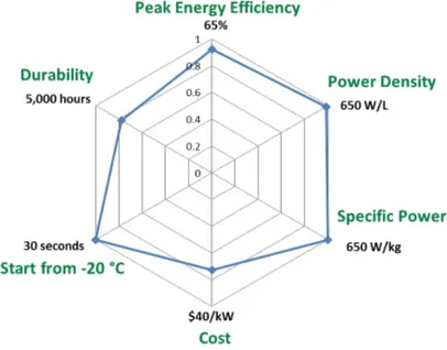
Fig. 1.2.: Fuel cells 2020 targets versus 2015 status (blue). The current status is indicated as a fraction of the targets
Of particular interest is the automotive application, with a focus on light-duty vehi-cles. 2020 targets of the research and development program of the U.S. Department
of Energy (DoE) are schematized by Figure 1.2 [12].
The system cost target is 40 $ kW-1, which is believed to be the point where fuel cell vehicles would be competitive on a life-cycle cost basis with incumbent and future competing technologies. Cost status is for a modeled system when manufactured at a volume of 500,000 units per year. A significant fraction of the cost of a PEM fuel cell comes from the Precious Group Metal (PGM) catalysts that are currently used on the anode and especially on the cathode for the electrochemical reactions. The durability goal of 5,000 hours is equivalent to approximately 150,000 miles of driving. The durability of catalysts can be compromised by platinum sintering and dissolution, especially under conditions of load-cycling and high electrode potentials.
Carbon support corrosion is another challenge at high electrode potentials and can worsen under load cycling. Membrane durability is affected instead by both humidity variations, which cause mechanical stresses from swelling and shrinking, and chemical degradation, which can be accelerated by products coming from the bipolar plates (which are also a good part of the stack cost) and other components. Cost, efficiency, and packaging of components for air, thermal, and water man-agement are also barriers to the commercialization of fuel cells in transportation applications. Air management is an obstacle because today’s compressor technologies are not optimized for automotive fuel cell applications. The low working tempera-tures create a small differential between the operating and ambient temperatempera-tures necessitating therefore large heat exchangers and humidifiers. These components increase the cost and complexity of the system and use some of the power that is produced, reducing the overall efficiency. Additional efforts would be needed for the integration of components into a complete automotive system that meets durability requirements in real-world conditions, since the projected cost status is based on an analysis of state-of-the-art components that have been developed and demonstrated only at laboratory scale.
In this context, the efforts of the research community are going towards a reduction of the costs by means of the employment of alternative cathode catalysts free of precious materials.
1.3 State of the art of the PGM-Free PEMFC
The state of the art of the PGM-Free PEMFCs is constantly being revised, several research groups have reported in the recent years significant progress in synthesis of highly active and durable catalysts. At the heart of improving non-precious electrodes lies the mystery of the atomic scale structure of the active sites. Due to the pyrolysis of precursors in the catalytic materials synthesis, a wide variety of structures are formed and understanding which component is responsible for ORR activity is still debated. The following paragraphs are thus intended to offer an updated view of the cathode structure, highlighting the features that has to be met in order to have an activity and a durability that would make the PGM-Free PEMFCs competitive with platinum based cells. On the other side, the utilization of Earth-abundant materials triggers degradation mechanisms not yet faced by traditional PEMFCs: those have been looked for in literature and consequently summarized.
1.3.1 Catalyst structure
The challenge for an innovative electrode morphology consists in linking the structure to the function: ORR activity depends on the active sites density (SD) within the
material and the turnover frequency of the sites (TOF). This is made explicit by the following relationship [30]:
i[A g−1] = F [A s mol−1] · T OF [electrons site−1s−1] · SD[mol g−1] (1.5)
where i is the gravimetric current density. Ideally, a material would have a high
SD of high TOF sites, so that many neighboring sites are easily interconnected and
reachable by electrons and protons, while keeping a high number of electrochemical conversions per second that the single catalytic site executes. However, exposure to electrochemical environments, which generally present an acidic and oxidative atmosphere, may lead to corrosive attacks or poisonings of active sites leading to a loss of activity. As such, active sites should be resistant to these phenomena, in order to successfully function under the requested operating conditions for long periods. It is thus necessary to relate ORR with the morphology of the catalyst, taking into account the probability of a certain variation of the structures to happen and the stability they may have relative to other structures [19].
One rapidly developing class of PGM-Free CCL are nanomaterials based on transition Metal-Carbon-Nitrogen (M-N-C) network, where nitrogen helps attach the transi-tion metals to the underlying carbon support creating the ORR active sites [21]. Transition metals have been preferred to pure ones by observing a much smaller current density of the latter compared to Pt/C catalysts. Transition metal macrocyclic compounds are rather interesting as they provide various pathways for reducing oxygen, as described later in the section.
Carbon support works as a conductive support, which acts as a bridge between catalyst particles and establishes a continuous electronic pathway, while being chem-ically stable in acidic media. Active sites structures can be broken down into sites containing transition metals (metal bearing) and those that do not (metal free). By means of X-ray Photoelectron Spectroscopy (XPS), it has been documented that materials synthesized with metal precursors lead to significantly more active ORR catalysts [42] but it is possible that either the metal itself is a central part of the active site or acts to template formation of specific ORR active C-N structures. This distinction is made more complicated due to trace amounts of transition metals in many "metal free" materials [39]. The structure of the active sites is elusive for two reasons. First, the non-crystallographic ordering of the metal atoms requires the use of specific spectroscopic techniques; second, the simultaneous presence of
ORR active sites along with other metal based phases prevents the recording of the
spectroscopic fingerprint of active sites [48]. Evaluation of the Electrochemically
Active Surface Area (ECSA) is hence hardly manageable.
Density-Functional-Theory (DFT) based simulations have predicted the thermody-namic stability of TM-Nx(x = 2, 4) sites embedded in monolayer graphene modeled as the carbon support of PGM-Free catalysts; and the ORR pathway to be dependent on the level of TM-Nx coordination chemistry in the catalyst [47]. The unique
experimental identification of the reaction pathway, especially how many sites are involved in ORR is challenging. For example, an observed net 4 e-cathodic reaction (as seen in Equation 1.2) does not necessarily require a single site. The peroxide reaction intermediate can desorb from the first site and interact with another site that promotes the reduction of peroxide to the final product as seen in the following equations:
O2+ 2H++ 2e−→ H2O2 (1.6)
H2O2+ 2H++ 2e−→ 2H2O (1.7)
This possibility may especially occur in thicker electrodes where the probability of the desorbed intermediate to encounter a second site is comparatively high and ORR would be identified as a 4 e- process rather than a dual site 2 x 2 e-process. It is remarkable that, intrinsically, PGM-Free CCLs are on average ten-times thicker than Pt/C based catalysts (∼ 100µm vs ∼ 10µm) due to their low activity. Increasing the electrode thickness increases the proton and oxygen transport resistance, as well as making the cathode more susceptible to liquid water flooding. Therefore, understanding the relationship between catalyst architecture and performance is crucial for optimizing this thick component. According to the operating condition of the cell, it is observed that the ORR is far from being homogeneously distributed within the catalyst layer: it can be focused either near the membrane or at the interface with the Gas Diffusion Layer (GDL). This depends on the status of the ionic/electronic pathways, which can be affected by several factors, ranging from the age of the Membrane Electrode Assembly (MEA), the compression level and Nafion hydration [2].
The present work focuses on iron-based catalysts due to the nature of the tested samples. It has been proposed that most of the Fe-N-C catalytic sites consist of an iron cation coordinated by four pyridinic functionalities attached to the edges of two graphitic sheets [7]. DFT computations [23] show that the formation of graphitic in-plane Fe–N4sites in a carbon matrix is energetically favorable over the formation of Fe–N2 sites: ∆EF e−N4 = 1.83 eV vs ∆EF e−N2 = 4.39 eV, where the lowest formation energy indicates the highest relative stability. O2is chemisorbed on Fe–N4and Fe–N2sites, indicating that both sites initialize ORR, but Fe–N4sites are predicted to be prime candidate sites for ORR due to their higher stability and working electrode potential compared to Fe–N2sites.
The method involving the preparation of such electrodes includes sputtering and pyrolisis. An optimal heat treatment temperature is required as the ligands become denatured at high temperature, whereas catalyst formation does not take place at low temperatures. Moreover, this process helps in stabilization of transition metal macrocyclic complexes, as they lack of stability in acidic environment. During the pyrolisis at temperatures higher than 800◦C, the carbon support is partly gasified, resulting in a mass loss dependent on the duration of the treatment. The disordered
domains of the carbon support are preferentially gasified [7]. As a result, micropores (where the catalytic sites are hosted) are created in the carbon black particles. To a certain mass loss corresponds a certain activity, which has to be seeked through the CCL preparation method. The technology underlying the catalysts employed in this experimental work comes from the University of New Mexico: the so-called
Sacrificial Support Method (SSM) synthesis, by means of high temperature pyrolysis
in inert atmosphere and following etching of the sacrificial support template, pro-duces material with multiple surface defects within a carbonaceous network and an internal network of connected pores with tunable size distribution [38]. In order to meet automobile specifications, SSM has been optimized to: increase the number of defects and hence the dispersion of active sites in graphene nano-sheets, ensure integration of Nafion in the Fe-N-C catalyst, and improve water management in MEA. The pore structure is formed by two mechanisms: the removal of the silica support and the decomposition of organic molecules. Porosity and pore size distribution can be controlled by varying the silica to organic precursor ratio and/or by type of silica. The use of the SSM for the synthesis of the catalysts requires precursors that are: (1) carbon rich (preferring a disordered carbon content) - the amount of carbon atoms in the molecule of the N-C precursor should be high enough to form a porous, open-frame and microporous matrix as mentioned above, (2) nitrogen rich - as synthesis is performed in an inert atmosphere, all the nitrogen-containing moieties must be formed from nitrogen contained in the precursor itself and (3) thermally stable - volatile N-C precursors cannot be utilized [37] since the formation of active sites starts at temperatures higher than 700◦C. The choice is not trivial: NH3-pyrolized catalysts exhibit a much higher activity than Ar-pyrolized ones, thanks to the formation of nitrogen groups having a higher basicity boosting the intrinsic
ORR activity of Fe-N4-C12 moieties through chemical or electronic effects; but on the other hands they are much less durable, mostly due to a protonation and anion-binding effect of the same highly-basic surface N-groups [25].
Within the MEA there is a complex interplay between catalyst and ionomer af-fecting its overall performance [27]. The latter is made of the same Nafion as the polymeric membrane and provides for the transportation of ions to active sites and serves as a media to remove water from them. The effect of ionomer-to-catalyst ratio on the performance has to be understood and optimized. While the kinetic performance improves with higher Nafion content, likely due to better ionic transport and conductivity that create a greater number of interfaces with catalyst particles, the mass transport is hindered due to excess ionomer or water blocking the pores. Diffusion of produced water away from the active site is hampered, inducing flooding especially at higher current densities. One of the possible explanations for this loss in the performance is the excess Nafion separating the catalyst particles, breaking the electronic pathway and losing electronic conductivity. Examples of different ionomer content can be observed in Figure 1.3 [27], where the intensity of color
shows the local density of the material.
One way of compensating performance losses due to excess Nafion is to add
conduc-(a)35 wt% Naf (b)50 wt% Naf (c)60 wt% Naf
Fig. 1.3.: 3D volume renderings of PGM-Free CCLs
tive material, such as carbon [37]. Ideal carbon additive should improve conductivity and should not change the composition of the electrocatalysts by introducing chem-ical groups that may compromise its stability. Introduction of amorphous carbon and surface oxides may increase hydrophilicity, cause flooding and increase carbon corrosion hindering activity. Introduction of excess of graphitic carbon may on the other hand enhance hydrophobicity and worsen water transport properties. A trade-off must be thus reached according to each specific case.
1.3.2 Degradation mechanisms
Major advances in the ORR activity and power density of PGM-Free PEMFCs have been reported, the next scientific steps include an improved understanding of the degradation mechanisms. The necessity to integrate Fe-Nx-Cymoieties at the edge of or within the graphene sheets made the catalyst structure intrinsically more prone to degradation when subjected to high electric potential than Pt/C based cells. Using the data set available in literature, it becomes clear that there are two distinct time frames involved in stability (where stability is defined as performance loss following constant voltage/constant current experiments [3]) loss during MEA testing: a rapid - exponential - loss in the first 15 hours, and a more gradual but persistent loss during testing. Due to the rapid nature and magnitude of the initial worsening, its study is of critical importance.
Concerning durability, defined as performance loss following voltage cycling [3], the catalyst might be severely deteriorated by start-stop cycling (1.0-1.5 V) since the most of the catalyst is carbon: during the procedure surface oxides causing carbon corrosion are formed; they generate a passive film on the catalyst surface lowering the performances. Complete oxidation of carbon is also possible, which results in a
permanent loss of the material from the electrode [17].
Certainly the majority of work in the literature has focused on stability, with only limited studies on voltage cycling durability. This is likely due to the fact that only recently have PGM-Free PEMFCs demonstrated sufficient performance to warrant durability/voltage cycling experiments. On the other hand, the stability of the catalyst is inevitably tested during routine performance measurements, and thus significantly more data has been obtained for this mode of degradation. Accordingly, the present work is intended to deepen the nature of the stability degradation mechanisms. Four particular phenomena have been identified as the possible main reasons of this cell behavior: leaching of the non-precious metal catalyst, attack by H2O2(and/or free radicals),protonation of the active site or protonation of a N species neighboring the active site followed by anion adsorption, and micropore flooding. The first two mechanisms are linked to the loss of active sites, coming from their irreversible oxidation; while the other two are associated with deactivation, so change in chemical nature of, or inaccessibility of reactants to, the active sites. The next paragraphs are dedicated to an attentive description of each one of them.
Iron demetallation Fe-rich Fe-N-C catalysts comprising a significant amount of
inactive Fe particles are often characterized by a highly graphitic structure, since such Fe-based structures catalyze graphitization during pyrolysis [13]. The advantages of highly graphitic catalysts such as high resistance to chemical or electrochemical oxidation, and promotion for the formation or activation of other active species, like specific surface N groups, may not be fully exploited if they concomitantly release massive amounts of inactive Fe in PEMFCs. In recent studies [9], using an operando spectroscopic analysis, it has been demonstrated that demetallation of Fe-N-C catalysts initiates only below 0.7-0.8 VRHE but predominantly originates from the ORR-inactive Fe species, as schematized in Figure 1.4 [9], where inactive Fe particles exposed to the electrolyte are leached out during electrochemical operation after operando reduction from ferric to ferrous species.
Even though Fe leaching from ORR-inactive Fe species results intrinsically in no significant ORR activity decay, the released Fe ions may however still cause serious problems inside the MEA, such as the partial exchange of protons in the ionomer or the production of highly reactive radicals upon reactions with H2O2, whose consequences are discussed in the next paragraph. Therefore, the complete removal of leachable inactive Fe species before MEA fabrication might be pivotal for the successful introduction of Fe-N-C catalysts in commercial PEMFC systems.
Generally, an acid-washing step is applied after the synthesis of Fe-N-C catalysts and before electrochemical testing, in order to eliminate the inactive Fe species that are not completely surrounded by a carbon layer. This is a straightforward but fairly effective method, as previously confirmed by reduced bulk Fe contents in the catalysts following the acid washing [10]. Nevertheless, the acid washing has been proved
Fig. 1.4.: Polymorphic Fe-N-C catalyst including inactive Fe particles and active Fe moieties
[9] not to be able to fully dissolve the inactive Fe species exposed to the electrolyte. Any Fe particle that survives from the acid washing has therefore been assumed to be acid-stable, a property that has been assigned to the presence of a relatively high surface potential (∼ 0.9 VRHE) continuous graphitic layer surrounding such particles. Once the potential decreases, the experimentally observed Fe demetallation below 0.7 VRHE strongly suggests that Fe ions are released in the electrolyte in the form of ferrous ions as a consequence of the reduction of insoluble Fe species with higher oxidation state: i.e. ferric species. To minimize the operando Fe demetallation, a
(a)Synthetic approach (b)Post synthetic approach
Fig. 1.5.: Fe demetallation minimization strategies
synthetic strategy for the preparation of the catalysts free from inactive Fe particles has been successfully applied (Figure 1.5a [9]). Alternatively, it has been also demonstrated that ex-situ electrochemical Cyclic Voltammetry (CV), chemical control of OCV using SnCl2in an HCl solution, and their combination are highly effective to remove, after synthesis, inactive Fe species from the surface of the electrode without concurring loss of catalytic activity (Figure 1.5b [9]).
In conclusion, while Fe leaching is potentially important for prolonged fuel cell operation, short durability tests have showed that operando Fe demetallation is not a primary degradation mechanism for Fe-N-C catalysts during 5-50 h of operation [9].
Hydrogen peroxide/Radical oxygen species formation The oxygen reduction
reac-tion happening at the fuel cell cathode can develop according to two different pathways. One is a 4 e-pathway in which O
2is reduced to 2H2O; the other is a 2 e-reduction of O2to the intermediate H2O2, which can be further oxidized on the
same site, or on another one, or can proceed in oxidative attacks against the active sites. The 4 e-ORR is thus always the desired pathway.
While the percentage of H2O2produced during ORR is often not much higher on
Fe-N-C than on Pt/C catalysts [43] [20], the residence time of H2O2in the electrode may be longer with Fe-N-C catalysts due to their extremely poor activity for the electro-reduction of H2O2to H2O [8] and poor activity for the chemical dispropor-tionation of H2O2. Chemical disproportionation of H2O2 is about two orders of magnitude faster at high pH for such catalysts [41], highlighting the possibility to recycle H2O2at high pH but impossibility to do so at low pH. In contrast, platinum is an excellent catalyst for both the 4 e-reduction and the 2 e-reduction of H2O2to H2O [22]. The important difference between the durability of Pt/C and Fe-N-C cata-lysts in PEMFC may thus stem from their different reactivity toward H2O2. Moreover, chemical disproportionation of H2O2on Fe-N-C catalysts via Fenton chemistry might produce a significant amount of Radical Oxygen Species (ROS) [16].
In order to understand the role of H2O2in the degradation of Fe-N-C based cathodes during PEMFC steady state operation, recent studies [15] have synthesized this type of catalyst and contacted it with various amounts of H2O2corresponding to ratios of moles H2O2per mass of catalyst ranging over circa two orders of magnitudes. Electrochemical activity of the catalysts toward the ORR has been determined using the Rotating Disc Electrode (RDE) technique. From polarization tests, it has been evinced that activity at 0.8 V vs SHE gradually decreases with increasing amounts of H2O2used during the treatment, while the diffusion-limited current density is practically unmodified. This suggests that the ORR mechanism is unchanged while the number of Fe-Nx-Cyactive sites on the surface gradually decreases. The general trend of worsening activity with increased amount of H2O2used in the treatment is however more complex at low peroxide amounts.
The same tests have been carried out for different transition metal based catalysts such as Co-N-C and Cr-N-C: the Tafel slopes appear to be constant with H2O2 treat-ment, except for pristine Fe-N-C for which the Tafel slope is slightly higher than that for treated samples. It follows that ORR activity decay after H2O2treatment strongly depends on the nature of the metal in Me-N-C catalysts, which in turn suggests that the oxidizing species degrading the catalysts is not H2O2 but rather the ROS generated via a Fenton reaction between transition metal atoms and H2O2. This is supported by the lower fluoride concentration and lower degradation measured for Co-N-C than for Fe-N-C after peroxide treatment.
Absorption Near Edge Structure (XANES) spectra of the Fe-based series show that
the coordination chemistry of the Fe atoms remaining in the samples after H2O2 treatment is identical to the one before treatment, while the metal content decreases and ORR activity super-proportionally worsens. The bulk-averaging nature of the detection leads to maintain the normalized XANES and EXAFS spectra unchanged even after a complete removal of top surface sites if similar Fe-Nx-Cymoieties are present both on the top surface and in the bulk of pristine Fe-N-C,. Hence, identical spectra before and after H2O2treatment suggest that only a fraction of the Fe-Nx-Cy moieties existing in pristine Fe-N-C are located on the top surface and so contributing to ORR activity. Alternatively, if a major fraction of moieties is located on the top surface initially, the results suggest a drastic reduction of the turnover frequency for
ORR of the remaining Fe-Nx-Cymoieties. In this second hypothesis, the fact that no modification of the spectra is observed, means that the oxidation mostly occurs on the N-doped carbon matrix.
Through XPS, a dramatic increase of total oxygen content after H2O2 treatment is made explicit. This is correlated with a large decrease in ORR activity. Surface oxidation of carbon thus seems to be the main degradation route during reaction with H2O2.
From a comparison between ex situ and operando degradation, the chemical attack of Fe-N-C by H2O2and ROS seems to be the main degradation mechanism in steady-state operation. To mitigate this main degradation mechanism, four strategies may be adopted: 1) synthesis of catalysts that minimizes percentage of H2O2 during oxygen reduction, 2) synthesis of catalysts that do not form ROS in the presence of H2O2, 3) addition of radical scavengers.
Protonation and Anion-binding The activity of Fe-N-C catalysts prepared through
pyrolysis in NH3 is mostly imparted by acid-resistant FeN4 sites whose turnover frequency for the O2reduction can be regulated by fine chemical changes of the catalyst surface.
Specific N-groups on the catalyst surface (and not involved in Fe coordination) protonate in acidic medium and bind anions, resulting in activity decay. The time scale for anion binding, and therefore for activity decay, greatly depends on the anion pervasiveness in the electrolyte: slow in a polymer electrolyte and fast in a liquid electrolyte. This has been demonstrated by investigating the effects of acid-washing on Fe-N-C catalysts [18]. It has been revealed that about half of the activity decay can be recovered ex situ either chemically or thermally at 300◦C in argon, a temperature at which no new active sites can be formed. Possibly, an increase in ORR turnover frequency of catalytic sites that were already present in the acid-washed catalyst takes place. This recovery coincides with the removal of anions that bound on the surface during the acid washing. Anion binding during acid washing implies the presence of positively charged groups on the catalyst surface.
Direct anion binding onto Fe ions can be discarded since no coordination change of Fe ions is detected by Mössbauer spectroscopy. Hence, the positively charged sites necessary to explain anion retention upon acid washing and rinsing could result from the protonation of surface functionalities having a basic character. Likely, these functionalities on the catalyst surface may be N functionalities. While the experimental results demonstrate that protonation of basic N-groups along with anion binding is marked by a decreased turnover frequency of FeN4sites for the ORR, the chemical state of the basic N-groups corresponding to the initial high turnover frequency of FeN4sites appears to be protonated but not anion bound.
The protonation of basic N-groups on the cathode catalyst surface may also occur as soon as the PEMFC generates current. Protons originating from the anode’s
HOR could protonate basic N-groups at the cathode, instead of participating in
the ORR. In a PEMFC cathode, the amount of protons fixed on specific N-groups is significant, especially if these N-groups are located in micropores, and could play an important role as a relay for the protons migrating from the Nafion ionomer toward the FeN4 centers found in the micropores. Consequently, electrons from the anode would accumulate at the cathode catalyst surface to compensate for the NH+-groups formed at the catalyst-electrolyte interface. Anion binding is delayed in PEMFC due to restricted mobility of the sulfonate groups of the membrane. Two activity enhancement effects related to the protonation of neighboring N-groups and that may be negated by subsequent anion binding are: modified electron density of the catalyst surface surrounding FeN4moieties, and increased proton access to FeN4 centers during the ORR.
In conclusion, combining high activity and durability will require optimizing the catalyst/electrolyte interface to prevent anion binding.
Micropore flooding Catalyst layer flooding is a well-known phenomenon that can
occur at high relative humidity/current densities and leads to mass transport losses. In traditional Pt/C PEMFC, the flooding is not specific of micropores, but extends to the entire hierarchy of pore sizes and performance can be recovered by changing operating conditions. This is contrary to the proposed mechanism of micropore flooding in PGM-Free PEMFCs, where the performance loss is considered irreversible [45].
Recent studies [11] have aimed at quantifying the impact of this phenomenon to cell performance stability. The initial situation of the micropore (d < 2 nm) is schematized by Figure 1.6 [11], where micropores are initially partially wet, but then completely filled when current is generated in the CCL. Ionomer is assumed not to be able to penetrate into the micropores, since Nafion micelles range in size from 1–5 nm [36]. The effect of micropore flooding can be evaluated by means of in situ polarization and CV.