SCUOLA DI INGEGNERIA E ARCHITETTURA
Dipartimento di Informatica-Scienza e Ingegneria (DISI)
INGEGNERIA INFORMATICA LM
TESI DI LAUREA
in
Reti di Calcolatori M
Integrating Wireless Sensor Networks and Internet-of-Things: a CoAP-based approach
CANDIDATO RELATORE:
Alessandro Aloisi Chiar.mo Prof. Antonio Corradi
CORRELATORE Dott.Ing.Stefan Forsström Dott.Ing. Luca Foschini
Anno Accademico 2013/2014
ment of pervasive applications which will enable access sensor data from remote locations in an Internet-of-Things (IoT) scenario. A scenario in which objects, animals or people are provided with sen-sors and the ability to automatically transfer data over the Internet is called IoT. Many smart sensing nodes that cooperate to sense the environment may form a Wireless Sensor Network (WSN), provid-ing sensprovid-ing services to an ever growprovid-ing application space. The the-sis focuses on enabling the communication between WSNs and IoT applications. In order to achieve this goal, the first step has been to investigate the concept of the IoT and then to understand how this scenario could be used to interconnect multiple WSNs in order to develop context-aware applications which could handle sensor data coming from this type of network. The architecture of WSNs was then analyzed followed by a survey about the operating systems and communication standards supported by these network. Finally, some IoT software platforms have been studied. The second step was to design and implement a communication stack which enabled WSNs to communicate with an IoT platform. The Constrained Ap-plication Protocol (CoAP) has been used as apAp-plication protocol for the communication with the WSNs. CoAP includes the HTTP func-tionalities which have been redesigned considering the low process-ing power and energy consumption constraints of small embedded devices, such as the WSNs. The solution has been developed in Java programming language and extended the sensor and actuator layer of the Sensible Things platform. The third step of this thesis has been to investigate in which real world applications the developed solution could have been used. Next a proof of concept application has been implemented in order to simulate a simple fire detection system, where multiple WSNs collaborate to send their temperature data to a control center. The last step was to evaluate the whole sys-tem, specifically the responsiveness and the overhead introduced by the developed communication stack. The results showed that the so-lution introduced just a little overhead to the platform and also that the value of the response time depends on the type of request sent to the WSN. However, the performances of the system could be im-proved further and suggested future work involves some policies to manage multiple CoAP transactions at the same time. Also the
chal-munication between the platform and sensor nodes, requires further work.
Acknowledgements
Firstly I would like to express my sincere gratitude to my super-visor Stefan Forsström for his patient guidance and his capacity to answer my numerous questions. Without his help and our nu-merous meetings, I could not have achieved the results that I had. Secondly, I would like to thank my examiner, Professor Ting Ting Zhang for her interest and helpful comments. Finally I would also like to thank my Italian exchange coordinator, Prof. Antonio Corradi and both University of Bologna and Mid Sweden University for giving me the chance to prepare this the-sis as an exchange student. It was a valuable experience for me and it helped greatly in improving my professional and social skills. Lastly, I would like to thank my family and my friends for their love and all the support given me during this period as an exchange student.
Table of Contents
Abstract...1
Acknowledgements...3
Acronyms Table...6
1 Introduction...1
1.1 Background and problem motivation...1
1.2 High-level problem statement...1
1.3 Concrete and verifiable goals...2
1.4 Scope...3 1.5 Outline...3 1.6 Contributions...4 2 Theory...5 2.1 Internet-of-Things...5 2.1.1 Context awareness...8 2.1.2 Ubiquitous computing...9 2.2 WSNs overview...9 2.2.1 WSN motes...12 2.3 WSNs' Operating Systems...14 2.3.1 TinyOS...14 2.3.2 Contiki...17
2.3.3 Tiny Os and Contiki evaluation...19
2.4 WSNs communication standards...20
2.4.1 IEEE 802.15.4...21
2.4.2 ZigBee...22
2.4.3 6LoWPAN...24
2.4.4 REST and CoAP...26
2.5 Related work...29 2.5.1 SensibleThings...29 2.5.2 ETSI M2M...32 2.5.3 SENSEWEB...33 3 Methodology...36 4 Implementation...38 4.1 SensibleThings platform...40
4.2 CoAP packet structure...41
4.3 CoapSensorActuator...44
4.4 CoapSensorGateway...49
5 Results...51
5.1 Response time...51
5.1.1 CoapSensorActuator response time...51
5.1.2 CoapSensorGateway response time...56
5.3 Scalability...61
5.4 Proof of concept application...64
5.4.1 Potential real-world scenario...64
5.4.2 Implementation and results...65
5.5 A battery-saving algorithm...67 6 Conclusion...71 6.1 Discussion...72 6.1.1 Ethical issues...74 6.2 Future work...75 References...77
Appendix A: CoapBlip installation guide...81
Acronyms Table
6LoWPAN: IPv6 over Low power Wireless Personal Area Net-works
AODV: Ad-hoc On Demand Distance Vector Routing
ASCII: American Standard Code for Information Interchange CoAP: Constrained Application Protocol
FFD: Full Function Device IoT: Internet of Things
ISM: Industrial, Scientific and Medical Radio Bands LAN: Local Area Network
LLN: Low Power and Lossy Network M2M: Machine to Machine
MAC: Media Access Control
NFC: Near Field Communications PAN: Personal Area Network
PPP: Point to Point Protocol
REST: Representational State Transfer RFD: Reduced Function Device
RFID: Radio Frequency Identification TCP: Transmission Control Protocol TLV: Type Length Format
UDP: User Datagram Protocol URI: Universal Resource Identifier
WSAN: Wireless Sensor and Actuator Network. WSN: Wireless Sensor Network
1
Introduction
This report is a Master's thesis in Computer Science Engineer-ing and it has been prepared in collaboration with Mid Sweden University in Sundsvall, Sweden. I am an exchange student from the University of Bologna (Italy) and I worked on this the-sis within the Erasmus Exchange Program. This thethe-sis deals with the challenging question of how to interconnect WSNs over the Internet and describes a solution that has been devel-oped within this thesis work.
1.1
Background and problem motivation
Historically, humankind has seen the emergence of different kinds of global data fields. The planet itself has always gener-ated an enormous amount of data, as human systems and physi-cal objects did too, but until recent years we were unable to capture it. We now can because we are able to embed sensors in all sort of things and to use them to retrieve data, in a so called IoT scenario. This kind of network can then be used by applica-tions that utilize information from sensors attached to different things in order to display context-aware behavior. However, since not all sensors may be directly connected to a device, they could be gathered in local networks such as the WSNs, which nowadays are the most used technology in this field. WSNs are composed of a large number of radio equipped sensor devices that autonomously form a network, through which sensors are capable of sensing, processing and communicating with each other. These networks can operate as standalone networks or be connected to other networks, but for many applications they do not work efficiently in full isolation. Therefore, one of the big-gest challenges for the IoT developers is to find resources on how to interconnect several WSNs over the Internet.
1.2
High-level problem statement
WSNs rely on the collaborative efforts of many small wireless sensor nodes and on their ability to form networks which can be
used to gather sensor information. Most sensor networks are usually deployed over a wide geographical area and their appli-cations aim at monitoring or detecting phenomena. For such applications, WSNs cannot operate efficiently in complete iso-lation because there should be a way for a remote user to gain access to the data produced by the network. By connecting these networks to an existing network infrastructure, remote ac-cess to the sensor data can be achieved. Since the Internet has the most widespread network infrastructure in the world, it is logical to look at some efficient methods for interconnecting WSNs over the Internet; in order to make an IoT. Many IoT software platforms have already been developed in order to en-able remote access to sensor data, but just a small quantity of these platforms deal with WSNs. Thus, a communication stack is required for implementation in order to enable communica-tion between IoT applicacommunica-tions and WSNs. Another big chal-lenge is the high heterogeneity between WSNs, since these net-works often are intended to run specialized communication pro-tocols. As a consequence of this scenario, it is usually impossi-ble to directly connect WSNs to the Internet. Therefore, there is also the need to implement a second stack, which is able to ex-port sensor data from these particular networks to other devices connected to the Internet. Therefore, this thesis will attempt to solve the following problem:
Enabling communication between IoT and WSNs, irregard-less of their network connection and then to utilize the sen-sor information available in WSNs for context aware appli-cations.
1.3
Concrete and verifiable goals
In order to solve the problem of this project, the following goals have to be accomplished:
1. Find three different solutions of connecting WSNs to an IoT.
2. Determine the most common operating systems used in WSNs.
3. Investigate which communication protocols these operat-ing systems support.
4. Implement a communication stack which enables com-munication between WSNs and IoT platforms.
5. Evaluate the performance and responsiveness of the im-plemented solution.
6. Find possible real world applications for the implemented solution in order to put together several WSNs, defining policies for system federation and coordination.
1.4
Scope
This project is focused on creating a communication stack be-tween IoT applications and wireless sensors and actuator net-works and then to create a proof of concept application in order to evaluate it. However, since there are many different operat-ing systems and communication protocols for WSNs, in this thesis I will focus on how to enable communication only with networks which use the most common ones. The management of the physical layer below these systems and security issues are out of scope for this project.
1.5
Outline
The second chapter will present the general idea of IoT and context awareness including the specific devices and protocols which have been developed in order to spread its diffusion. Next, some of the most popular IoT platforms are presented. The third chapter is about the methodology we used for the project. In this section all the goals that have been presented in this thesis are listed. The fourth chapter explains the approach that has been used in the project's implementation. In chapter five the tests made and their results are reported. Finally, the sixth chapter presents the conclusions and then discusses future work needed for this project.
1.6
Contributions
The SensibleThings platform and its source code was contrib-uted by and is property of Mid Sweden University. My thesis work has contributed by adding functionalities to the existing framework in order to enable communication between IoT ap-plications and WSNs. The developed communication stack is independent of the platform itself, therefore it is possible to eas-ily export it to any kind of implementation of the latter.
2
Theory
A first important step is to categorize the state of art based on current research literature. The following sections present the background theory and related work for this thesis. The first section provides a short introduction about the IoT concept and also about context awareness and ubiquitous computing. The second section gives an overview of the WSN technology and then a list of the most common motes. In the third section, two of the most used WSN Operating System are presented and a comparison between them has been made. The fourth section provides an overview of the communication standards used in WSNs. Finally, in the fifth section, three IoT platforms are pre-sented.
2.1
Internet-of-Things
The Internet-of-Things is a novel paradigm that is rapidly spreading across the scenario of modern wireless telecommuni-cations. This concept is based on is the pervasive presence around us of a variety of things or objects which, through unique addressing schemes, are able to interact and cooperate with each other in order to reach common goals. As the name suggests, the purpose of this architecture is to interconnect all kinds of objects over the Internet. It is considered a normal evo-lution of the Internet, which at the beginning was meant just to interconnect computers but now is developing into a world wide network which will be able to interconnect all kinds of devices; as represented in Figure 2.1.
However, IoT is a very broad vision, so the IoT research is still in progress. Therefore, there are many definitions of IoT within the research community but there are no standard definitions for IoT as of yet. The term ‘IoT’ was originally introduced by Kevin Ashton [2] in a presentation in 1999. He noted that “The IoT has the potential to change the world, just as the Internet did. Maybe even more so”.
Figure 2.1: Evolution of the Internet [1].
The very first vision of IoT was presented by the Auto-ID Labs [3], a world-wide network of academic research laboratories in the field of networked RFID and emerging sensing technolo-gies. The group perceived things as very simple items: Radio-Frequency IDentification (RFID) tags having a unique identifier called Electronic Product Code. Their purpose was to realize a global system for object visibility (i.e. the traceability of an ob-ject and the awareness of its status).
However, according to the authors of [4], RFID still stands at the forefront of the technologies driving the vision just because of its maturity, low cost, and strong support from the business community. The group believes that a wide range of device, network, and service technologies will eventually build up the IoT. Near Field Communications (NFC) and Wireless Sensor and Actuator Networks (WSAN) together with RFID are recog-nized as ‘‘the atomic components that will link the real world with the digital world”. According to this heterogeneity, the fol-lowing definitions are essential to understand the IoT:
Definition by [5]: “The IoT allows people and things to be
connected Anytime, Anyplace, with Anything and Anyone, ideally using Any path/network and Any service.”
Figure 2.2: Representation of the first definition of IoT. Definition by [6]:“The semantic origin of the expression
is composed by two words and concepts: Internet and Thing, where Internet can be defined as the world-wide network of interconnected computer networks, based on a standard communication protocol, the Internet suite (TCP/IP), while Thing is an object not precisely identifi-able. Therefore, semantically, IoT means a world-wide network of interconnected objects uniquely addressable, based on standard communication protocols.”
Many relevant institutions have stressed the concept that the road to full IoT deployment has to start from the augmentation in the Things’ intelligence. This is why a concept that emerged in parallel with IoT is the concept of Smart Items, as a refine-ment of the general “Things” definition. Smart items are de-fined as:
objects that can be tracked through space and time through-out their lifetime and that will be sustainable, enhanceable, and uniquely identifiable”[7]. “These are a sort of sensors not only equipped with usual wireless communication, memory, and elaboration capabilities, but also with new po-tentials. Autonomous and proactive behavior, context
awareness, collaborative communications and elaboration are just some required capabilities [8].
The IoT infrastructure allows combinations of different types of smart items, using different but interoperable communication protocols and realizes a dynamic heterogeneous network that can be deployed also in inaccessible, or remote spaces (oil platforms, mines, forests, tunnels, pipes, etc.) or in cases of emergencies or hazardous situations (earthquakes, fire, floods, radiation areas, etc.). Giving these objects the possibility to communicate with each other and to elaborate the information retrieved from the surroundings implies having different areas where a wide range of applications can be deployed. These can be grouped into the following domains: healthcare, personal and social, smart environment (such as at home or in the of-fice), futuristic applications, transportation and logistics; as rep-resented in Figure 2.3.
Figure 2.3: IoT application areas [8].
2.1.1 Context awareness
Context awareness plays an important role in the IoT to enable services customization according to the immediate situation with minimal human intervention. Acquiring, analyzing, and
in-terpreting relevant context information regarding the user will be a key ingredient to create a whole new range of smart appli-cations. The concept of context is commonly understood as the situation or surroundings of an entity. The main definition of context has been given by Dey and Abowd [9]:”Context is any
information that can be used to characterize the situation of an entity. An entity is a person, place, or object that is considered relevant to the interaction between a user and an application, including the user and applications themselves.”. Therefore,
context awareness is the result gained from utilizing context information, such as the ability to adapt behavior depending on the current situation of the users in context-aware applications. Dey and Abowd [9] gave this definition of context aware-ness:”A system is context-aware if it uses context to provide
rel-evant information and/or services to the user, where relevancy depends on the users task.”
2.1.2 Ubiquitous computing
The focus on context-aware computing evolved from desktop applications, web applications, mobile computing, ubiquitous computing to the IoT over the last decade. However, context-aware computing became more popular with the introduction of the term ‘ubiquitous computing’ by Mark Weiser [10], in his pa-per “The Computer for the 21st Century in 1991”. He described
a new era in which computer devices will be embedded in ev-eryday objects, invisible at work in the environment around us; in which intelligent, intuitive interfaces will make computer de-vices simple to use and in which communication networks will connect these devices together to facilitate anywhere, anytime, always-on communication. Ubiquitous computing then, “is the
growing trend towards embedding microprocessors in everyday objects and refers to how they might communicate and process information, creating a world in which things can interact dynamically”.
2.2
WSNs overview
WSNs became one of the most interesting and researched areas in the field of electronics in the last decade. WSNs are
com-posed of a large number of radio equipped sensor devices that autonomously form a network, through which sensor nodes are capable of sensing, processing and communicating among each other. The sensor nodes are usually scattered in a sensor field as shown in Figure 2.4. Each of these sensor nodes has the capa-bility to collect data and route data back to the sink and the end users. Data are routed back to the end user by a multi-hop in-frastructureless architecture through the sink, which may com-municate with the end user via the Internet or any type of wire-less network (like WiFi, mesh networks, cellular systems, WiMAX, etc.), or without any of these networks where the sink can be directly connected to the end users [11]. There may be multiple sinks and multiple end users in the architecture shown in Figure 2.4.
Figure 2.4: WSN architecture [11].
Typical tasks for sensor nodes are: obtaining environmental data, storing, processing and transferring obtained data, receiv-ing data from other nodes, usreceiv-ing and forwardreceiv-ing received data. However, not every node in a sensor network has to perform all of these tasks. The sensor nodes, which are intended to be phys-ically small and inexpensive, are equipped with one or more sensors for sensing operations, a short range radio transceiver in order to enable communication with other nodes, a small micro controller for computation, and a power supply in the form of a battery; as represented in Figure 2.5.
Figure 2.5: General sensor node structure. The main characteristics and challenges of WSNs are:
Dynamic topology: in many applications it is assumed that the
topology of the network is stationary. However, in reality it is not, because WSN topology can change frequently. The topol-ogy of the WSNs can vary from a simple star network to a tree network or even to an advanced multi-hop wireless mesh net-work.
Limited data rate and short distance: the sensor nodes
elec-tromagnetic range covers short distances (from one to several tens of meters). This determines the necessity of application multi-hop topology in WSN.
Different traffic intensity: the highest traffic density in WSN
takes place around the central sensor nodes (that is the sink), because it collects all data coming from other nodes located in its vicinity. Quite the opposite, very little traffic takes place around sensor nodes which directly collect data and in the other direction, from sink to these nodes.
Energy constraints: the constraint most often associated with
WSNs design is that sensor nodes operate with limited energy budgets. Typically, they are powered through batteries, which must be either replaced or recharged when depleted.
Self management: since many WSNs are required to operate in
remote areas and harsh environments, without infrastructure and the possibility for maintenance or repair, sensor nodes must be able to self-configure and adapt to failures.
WSNs may consist of many different types of sensors including seismic, magnetic, thermal, visual, infrared, acoustic and radar, which are able to monitor a wide variety of ambient conditions that include: temperature, humidity, pressure, speed, direction, movement, light, soil makeup, noise levels, the presence or ab-sence of certain kinds of objects, and mechanical stress levels on attached objects [11]. As a result, a wide range of applica-tions are possible. However, in order to extend the applicability of these architectures and provide useful information anytime and anywhere, their integration with the Internet is very impor-tant. It is for this reason that during recent years the IoT re-search community has focused on WSNs as the upcoming tech-nology for the IoT.
2.2.1 WSN motes
WSNs nodes are called “motes” and currently they range in size from disc shaped boards having diameters less than 1cm to en-closed systems with typical dimensions less than 5cm square. The term “mote” was coined by researchers in the Berkeley NEST to refer to these sensor nodes [13]. In Figure 2.6 a list of the most common motes is reported. The values within this ta-ble show that all the motes have approximately the same size but the lightest one is SHIMMER, which is also one of the most expensive. Regarding memory and CPU power all the motes are almost identical except for the Sun SPOT which is currently the most powerful but the most costly.
Width x Length x Height (cm) Weight (g) (with Battery) Cost (per node) Processor Memory RAM/FLASH/ EEPROM TelosB 3.2x6.6x0.7 63.05 139 $ 4-8 MHz 10 KB/48 KB/1 MB Crossbow Mica2 3.2x5.7x0.6 63.82 99 $ 8 MHz 4 KB/128 KB/512 KB SHIMME R 2x4.4x1.3 10.36 276 $ 4-8 MHz 10 KB/48 KB/none Crossbow IRIS 3.2x5.7x0.6 69.40 115 $ 8 MHz 8 KB/640 KB/4 KB Sun SPOT 6.4x3.8x2.5 58.08 750 $ 180 MHz 512 KB/4 MB/none
Figure 2.6: WSNs motes characteristics [13].
Each of these WSNs motes is equipped with a different set of sensors:
TelosB: it has a set of on-board sensors such as humidity,
tem-perature and light intensity. In addition to the on-board sensors, the Tmote Sky provides access to 6 ADC inputs, a UART and I2C bus and several general purpose ports.
Mica2: it is not equipped with on-board sensors. However,
Crossbow offers an extensive set of sensor boards that connect directly to the Mica mote, and are capable of measuring light, temperature, relative humidity, barometric pressure, accelera-tion/seismic activity, acoustics, magnetic fields and GPS posi-tion.
Shimmer: it has been designed for mobile health sensing
appli-cations. It incorporates a 3 axis accelerometer and allows con-nection of other sensors through its expansion board.
Iris: like the other mote from the Crossbow technology (Mica2
mote), it is not equipped with on-board sensors but it can be ex-tended with the same sensor boards provided for the Mica2 mote.
Sun SPOT: it offers expansion boards with tri-axial
ac-celerometer, temperature sensor and light sensors. Moreover, custom made sensors can be connected via five analogue inputs and five general purpose digital ports.
2.3
WSNs' Operating Systems
An operating system (OS) in a WSN is a thin software layer that logically resides between the node’s hardware and the ap-plication and provides basic programming abstractions to appli-cation developers. Its main task is to enable appliappli-cations to in-teract with hardware resources, to schedule and prioritize tasks, and to arbitrate between contending applications and services that try to seize resources. Other features of a WSNs OS are: memory and file management, power management, networking, providing programming environments. The choice of a particu-lar operating system depends on several factors such as: data types, scheduling, stacks, system calls, handling interrupts, multithreading and memory allocation [12]. OS for WSNs nodes are typically less complex than general purpose operating systems. They more strongly resemble embedded systems, for two reasons. First, WSNs are typically deployed with a particu-lar application in mind, rather than as a general platform. Sec-ond, a need for low costs and low power leads most wireless sensor nodes to have low power microcontrollers ensuring that mechanisms such as virtual memory are either unnecessary or too expensive to implement.
2.3.1 TinyOS
TinyOS is the most widely used runtime environment in WSNs and its compact architecture makes it suitable for supporting many applications. TinyOS has a component-based program-ming model, codified by the NesC language, a dialect of C and it is alsobased on an event driven programming model instead of multithreading. That means that when an external event oc-curs, such as an incoming data packet or a sensor reading, TinyOS signals the appropriate event handler to handle the event.
The architecture consists of a scheduler and a set of compo-nents each of which encapsulate a specific set of services, spec-ified by interfaces. An application connects components using a wiring specification that is independent of component imple-mentations. This wiring specification defines the complete set of components that the application uses. Components have three computational abstractions: commands, events and tasks.
Commands and events are mechanisms for inter-component
communication, while tasks are used to express intra-nent concurrency. A command is typically a request to a compo-nent to perform some service, such as initiating a sensor read-ing, while an event signals the completion of that service. Rather than performing a computation immediately, commands and event handlers may post a task, a function executed by the TinyOS scheduler at a later time. The standard TinyOS task scheduler uses a non-preemptive FIFO scheduling policy [14]. TinyOS abstracts all hardware resources as components and it provides a large number of components to application devel-opers, including abstractions for sensors, single-hop network-ing, ad hoc routnetwork-ing, power management, timers, and non volatile storage. A developer can then compose an application by writing components and wiring them to TinyOS components that provide implementations of the required services [14]. A component has two classes of interfaces: those it provides and those it uses. These interfaces define how the component directly interacts with other components. An interface generally models some service (e.g., sending a message) and is specified by an interface type. Interfaces contain both commands and
events and they are bidirectional which means that the
com-mands have to be implemented by the interface's provider whereas the events have to be implemented by the interface's user. The provided interfaces are intended to represent the func-tionality that the component provides to its user in its specifi-cation; the used interfaces represent the functionality the com-ponent needs to perform its job in its implementation.
NesC has two types of components: modules and
configura-tions. Modules provide code for defining Tiny OS components. Configurations are used to wire other components together,
connecting interfaces used by components to interfaces pro-vided by others. They allow multiple components to be aggre-gated together into a single “supercomponent” that exposes a single set of interfaces.
Figure 2.7 shows a simplified form of the TimerM component, a part of the TinyOS timer service, that provides the StdControl and Timer interfaces and uses a Clock interface.
Figure 2.7: Specification and graphical depiction of the TimerM component [14].
Figure 2.8 illustrates the TinyOS timer service, which is a con-figuration (TimerC) that wires the timer module (TimerM) to the hardware clock component (HWClock).
2.3.2 Contiki
Contiki is a lightweight operating system with support for dy-namic loading and replacement of individual programs and ser-vices. Contiki is built around an event driven kernel but pro-vides optional preemptive multithreading that can be applied to individual processes. Contiki is implemented in the C language and has been ported to a number of microcontroller architec-tures.
A running Contiki system consists of the kernel, libraries, the program loader, and a set of processes. A process may be either an application program or a service. A service implements func-tionalities used by more than one application process. All pro-cesses, both application programs and services, can be dynami-cally replaced at run time.
Communication between processes always goes through the kernel. The kernel does not provide a hardware abstraction layer, but lets device drivers and applications communicate di-rectly with the hardware. A process is defined by an event han-dler function and an optional poll hanhan-dler function; interprocess
communication is done by posting events [15].
A Contiki system is partitioned into two parts: the core and the loaded programs as shown in Figure 2.9. The core is made up of the Contiki kernel, the program loader, the most commonly used parts of the language run time and support libraries, and a communication stack with device drivers for the communica-tion hardware. This part of the operating system cannot be mod-ified dynamically.
Figure 2.9: Contiki system partitioning[15].
The partitioning is made at compile time and is specific to the deployment in which Contiki is used.
The kernel is the central element of the OS. Its basic assign-ment is to dispatch events and to periodically call polling han-dlers. Subsequently, a program execution in Contiki is triggered by either events that are dispatched by the kernel or through the polling mechanism. Event handlers process an event to com-pletion, unless they are preempted by interrupts or other mech-anisms, such as thread preemption in a multithreading scenario. The kernel supports synchronous and asynchronous events. Synchronous events are dispatched to the target process as soon as possible and control is returned to the posting process once the event is processed to the end. Asynchronous events, on the other hand, are dispatched at a convenient time. In addition to these events, the kernel provides a polling mechanism, in which the status of hardware components is sampled periodically [12]. One of the interesting features of the Contiki OS is its support of dynamic loading and reconfiguration of services. This is achieved by defining services, service interfaces, service stubs, and a service layer. Services are to Contiki what modules are to TinyOS, that is a process that implements functionality that can be used by other processes. A Contiki service consists of a
ser-vice interface and its implementation, which is also called a
process. The service interface consists of a version number and the list of functions with pointers to the functions that
imple-ment the interface. A service stub enables an application pro-gram to dynamically communicate with a service through its
service interface. A service layer is similar to a lookup service
or a registry service. Active services register by providing the description of their service interface and ID and version num-ber. This way, the service layer keeps track of all active ser-vices. Figure 2.10 illustrates how application programs interact with Contiki services [12].
Figure 2.10: Contiki service interaction architecture [12]. When a service is called, the service interface stub queries the service layer and obtains a pointer to the service interface. Upon obtaining a service whose interface description as well as version number matches with the service stub, the interface stub calls the implementation of the requested function.
2.3.3 Tiny Os and Contiki evaluation
Ranking the strength of an operating system, like all ranking assignments, is a difficult assignment. However, in WSNs, there are several contexts pertaining to development, deployment, runtime performance, and code evolution. In view of these as-pects, TinyOS is compact in size and efficient in its use of re-sources, since the cost of managing separate entities (operation system and application) is related to a single assignment of managing a single file. But replacement or reprogramming cost is high.
Contiki provides a flexible support for dynamic reprogramming and hence is well suited to applications which require intensive updating and upgrading processes; but this does not come with-out any costs.
Figure 2.11 and 2.12 provide summaries of the functional and nonfunctional aspects of both the OSs.
Figure 2.11: Comparision of functional aspects of the OS [12].
Figure 2.12: Comparision of non-functional aspects of the OS [12].
2.4
WSNs communication standards
In order to achieve interoperability between manufacturer components, a number of standards have been established in the WSN field. These standards can be mapped to the ISO-OSI lay-ers. However, some standards cover only the bottom layers, others cover the full stack. No single standard has been estab-lished as the market winner. The most common standards used
in WSN are: WiFi, Bluetooth, IEEE 802.15.4, ZigBee, 6LoW-PAN. However, WiFi and Bluetooth are losing ground within the WSNs research community since they were not developed for low power devices such as WSNs nodes. On the other hand, IEEE 802.15.4 was created just for these kinds of devices and is thus becoming the most important communication standard for WSNs. Moreover, the ZigBee and 6LoWPAN standards have been developed in order to extend the features of IEEE 802.15.4.
2.4.1 IEEE 802.15.4
The key requirements for Low Rata Personal Area Networks (as the WSNs) are low complexity, very low power consumption and low cost. The IEEE 802.15.4 standard considers these re-quirements and provides a framework for the lowest two layers of the OSI mode. The standard defines two types of devices: a Full Function Device (FFD) and a Reduced Function Device (RFD). The FFD is capable of all network functionalities and can operate in three different modes: it can operate as a PAN coordinator, a coordinator or it can serve simply as a device. An RFD device is low on resources and memory capacity and is ca-pable only of very simple applications such as sensing light or temperature [16]. There are two different topologies in which the PAN can operate: star or peer to peer, as represented in Fig-ure 2.13. In the star topology communication can only take place between the devices and the PAN coordinator, which has to be a FFD. The PAN coordinator is responsible for inaugurat-ing or terminatinaugurat-ing communications in the network and is often mains powered. In the peer to peer topology all FFD devices in the network can communicate with each other while the RFD devices can only communicate with the PAN coordinator [16]. The physical layer is responsible for the transmission and re-ception of data. It defines the radio bands to be used and type of spreading and modulation techniques. The standard provide three different operational frequencies: 16 channels in the 2.4 GHz band, 10 channels in the 915 MHz band and 1 channel in the 868 MHz band.
Figure 2.13 IEEE 802.15.4 network topology [16].
The MAC layer which appears just above the physical layer in the OSI model, is responsible for managing beacon transmis-sion, access to channel and association/disassociation to the net-work.
The IEEE 802.15.4 standard defines four basic frame types which are beacon, used by a coordinator to transmit beacons, a
data frame, used for all transfers of data, an acknowledgment frame, used for confirming successful frame reception and a MAC command frame, used for handling all MAC peer entity
control transfers.
2.4.2 ZigBee
ZigBee is a specification for a suite of high level communica-tion protocols used to create personal area networks; built for small, low power digital radios based on the IEEE 802.15.4 standard. ZigBee is used in applications that require a low data rate, long battery life, and secure networking. This standard has a defined rate of 250 kbit/s, best suited for periodic or intermit-tent data or a single signal transmission from a sensor or input device. The transmission distances range from 10 to 100 meters line of sight, depending on power output and environmental characteristics. The technology defined by the ZigBee specifi-cation is intended to be simpler and less expensive than other WPANs, such as Bluetooth or Wi-Fi.
The ZigBee standard defines a stack shown in Figure 2.14 which has a layered structure with four distinct layers, the
phys-ical layer, the MAC layer, the network layer and the application layer. The two bottom layers are defined by the IEEE 802.15.4 standard. The network layer is the bottom layer defined by the ZigBee standard which provides network configuration, ma-nipulation, and message routing. The routing protocol used by the network layer is the Ad-hoc On-Demand Distance Vector Routing Protocol (AODV). In order to find the destination de-vice, it broadcasts out a route request to all of its neighbors. The neighbors then broadcast the request to their neighbors, until the destination is reached. Once the destination is reached, it sends its route reply via unicast transmission following the low-est cost path back to the source. Once the source receives the reply, it will update its routing table for the destination address with the next hop in the path and the path cost. An application layer then provides the intended function of the device [17].
Figure 2.14: ZigBee stack architecture.
ZigBee operates in the industrial, scientific and medical (ISM) radio bands: 868 MHz in Europe, 915 MHz in the USA and Australia and 2.4 GHz in most jurisdictions worldwide. Data transmission rates vary from 20 kilobits/second in the 868 MHz frequency band to 250 kilobits/second in the 2.4 GHz frequency band. The ZigBee network layer natively supports both star and tree typical networks, and generic mesh networks; as reported in Figure 2.15. Every network must have one coordinator
de-vice, tasked with its creation, the control of its parameters and basic maintenance. Within star networks, the coordinator must be the central node. Both trees and meshes allow the use of Zig-Bee routers to extend communication at the network level [18].
Figure 2.15 ZigBee network topologies.
2.4.3 6LoWPAN
6LoWPAN is an acronym of IPv6 over Low power Wireless Personal Area Networks (WPAN). 6LoWPAN is the name of a working group in the Internet area of the Internet Engineering Task Force (IETF). The 6LoWPAN concept originated from the idea that “the Internet Protocol (IP) could and should be applied even to the smallest devices" and that low power devices with limited processing capabilities should be able to participate in the IoT [19]. 6LoWPAN enables the use of IPv6 in Low Power and Lossy Networks (LLNs), such as those based on the IEEE 802.15.4 standard. Given the limited packet size and other con-straints of this kind of devices, they cannot use the standard IPv6 directly. Therefore, an adaptation layer to perform header compression, fragmentation and address auto configuration is needed to use IPv6. The 6LoWPAN group thereby has encapsu-lation and header compression mechanisms that allow IPv6 packets to be sent to and received from over IEEE 802.15.4 based networks.
The 6LoWPAN architecture is made up of low-power wireless area networks (LoWPANs), which are connected to other IP networks through edge routers, as is shown in Figure 2.16. The edge router plays an important role as it routes traffic in and out of the LoWPAN, while handling 6LoWPAN compression and NeighborDiscovery for the LoWPAN [19].
Each LoWPAN node is identified by a unique IPv6 address, and is capable of sending and receiving IPv6 packets. Typically LoWPAN nodes support ICMPv6 traffic and use the User Data-gram Protocol (UDP) as a transport protocol. The whole 6LoW-PAN protocol stack is shown in Figure 2.17.
Figure 2.17 6LoWPAN protocol stack.
2.4.4 REST and CoAP
One of the major benefits of IP based networking in LLNs is to enable the use of standard web service architectures without us-ing application gateways. As a consequence, smart objects will not only be integrated with the Internet but also with the web. This integration allows smart object applications to be built on top of Representational State Transfer (REST) architectures and it is defined as the Web of Things (WoT) [20].
In a REST architecture a resource is an abstraction controlled by the server and identified by a Universal Resource Identifier (URI). The resources are accessed and manipulated by an appli-cation protocol based on client/server request/responses. REST is not tied to a particular application protocol, however, the vast majority of REST architectures currently use Hypertext Transfer Protocol (HTTP). HTTP manipulates resources by means of its methods GET, POST, PUT, DELETE [20].
REST architectures allow IoT applications to be developed on top of web services. However, the standard HTTP protocol can-not be used in LLNs since this protocol is relatively expensive for them, both in implementation code space and network re-source usage. Therefore, the Constrained RESTful environ-ments (CoRE) working group has defined a REST-based web transfer protocol called Constrained Application Protocol (CoAP). CoAP includes the HTTP functionalities which have been redesigned considering the low processing power and en-ergy consumption constraints of small embedded devices [20]. CoAP is based on a REST architecture in which resources are server controlled abstractions made available by an application
process and identified by Universal Resource Identifiers (URIs) and they can be manipulated by means of the same methods as the ones used by HTTP.
The first significant difference between HTTP and CoAP is the transport layer. HTTP relies on the Transmission Control Proto-col (TCP). TCP’ flow control mechanism is not appropriate for LLNs and its overhead is considered too high. Therefore CoAP has been built on top of the User Datagram Protocol (UDP), which has significantly lower overhead. As represented in Fig-ure 2.18, CoAP is organized in two layers. The transaction layer handles the single message exchange between end points, which can be of four types: Confirmable (it requires an knowledgment), Non-confirmable (it does not need to be ac-knowledged), Acknowledgment (it acknowledges a Con-firmable message) and Reset (it indicates that a ConCon-firmable message has been received but context is missing to be pro-cessed). It also provides support for multicast and congestion control.
Figure 2.18 CoAP protocol stack [20].
The Request/Response layer is responsible for the transmission of requests and responses for the resource manipulation and transmission. A REST request is piggybacked on a Confirmable or Non-confirmable message, while a REST response is piggy-backed on the related Acknowledgment message. Figure 2.19 shows an example of a typical REST request-response transac-tion.
Figure 2.19 CoAP request-response example, using a con-firmable message.
The dual layer approach allows CoAP to provide reliability mechanisms even without the use of TCP as transport protocol. In fact, a Confirmable message is retransmitted using a default timeout and exponential back off between retransmissions, until the recipient sends the Acknowledgement message. In addition, it enables asynchronous communication, because when a CoAP server receives a request which is not able to handle immedi-ately, it first acknowledges the reception of the message and sends back the response in an off-line fashion [20].
One of the major design goals of CoAP has been to keep the message overhead as small as possible and limit the use of frag-mentation. CoAP uses a short fixed length compact binary header of 4 bytes followed by compact binary options. A typical request has a total header of about 10-20 bytes.
Since a resource on a CoAP server likely changes over time, the protocol allows a client to constantly observe the resources. In a GET request, a client can indicate its interest in further updates from a resource by specifying the “Observe” option. If the server accepts this option, whenever the state of the resource changes it notifies each client having an observation ship with the resource. The duration of the observation relation-ship is negotiated during the registration procedure.
Although CoAP is a work in progress, various open source im-plementations are already available. The two most known oper-ating systems for WSNs, Contiki and Tiny OS, have already re-leased CoAP implementation libraries, named Erbium and CoapBlib respectively.
2.5
Related work
Applications that utilize information from sensors attached to different things in order to provide more personalized, automa-tized, or even intelligent behavior are commonly referred to as IoT applications [8]. The prediction is that these kinds of appli-cations will be able to interact with an IoT, a worldwide net-work of interconnected everyday objects, and thereby be able to display context-aware behavior [21]. There is also an interest-ing relationship between the IoT and big data, since all of the connected things will produce and consume large amounts of data. In order to enable a widespread proliferation of IoT ser-vices there must be a common platform for dissemination of sensor and actuator information on a global scale. However, there is a large number of practical difficulties that must be solved to achieve this goal. The main requirements that an IoT platform should satisfy are the following:
Scalable: logarithmic or better scaling of communication load
in end points;
No central point of failure: fully distributed platform;
Bidirectional: enabling communication between
sensors/actua-tors and the IoT applications in both ways;
Fast: capable of signaling in real time between end points; Lightweight: able to run on devices with limited resources; Seamless: capable of handling heterogeneous infrastructures
and different end user devices;
Stable: all queries into the platform should return an answer; Extensible: capable of adding new features and modules
with-out complete redistribution.
2.5.1 SensibleThings
The SensibleThings platform is an open source architecture for enabling IoT based applications, developed by Mid Sweden
University. An overview of the platform and its components is presented in Figure 2.20. It shows how the platform is distrib-uted over a number of entities connected to the Internet. The Figure shows how an application which is running a client of the SensibleThings platform (SensibleThinghs instance) com-municates with other entities running the platform. A client can acquire sensor and actuator information of the other partici-pants. Furthermore, the platform can act as both a producer and consumer of sensor and actuator information at the same time, enabling bidirectional exchange of context information [22].
Figure 2.20: Overview on the function of the SensibleThings platform.
The SensibleThing platform is a realization and implementation of the MediaSense architecture explained in [22]. The code is based on a fork of the MediaSense platform, but with signifi-cant improvement. The focus has been on the open source as-pect and maintaining the commercialization possibilities of ap-plications that are utilizing the platform. The platform is orga-nized in several levels, as represented in Figure 2.21.
Figure 2.21: SensibleThings platform architecture.
Interface Layer: the public interface through which
applica-tions interact with the SensibleThings platform, using its API's.
Add in Layer: enables developers to add optional functionality
and optimization algorithms to the platform, which can be loaded and unloaded in runtime when needed.
Dissemination Layer: it enables dissemination of information
between all entities that participate in the system and are con-nected to the platform. Therefore, it enables registration of sen-sors in the platform, resolving the location of a sensor in order to find it, and the communication to retrieve the actual sensor values.
Networking Layer: it manages connection of different entities
over current Internet Protocol (IP) based infrastructure.
Sensor and Actuator Layer: it enables different sensors and
actuators to connect into the platform into two different ways. If they are accessible from the application code, they can be nected directly. Otherwise, the sensors and actuators can con-nect through the sensor and actuator abstraction, which enables connectivity either directly to WSNs or via more powerful gate-ways.
2.5.2 ETSI M2M
The ETSI Machine to Machine (M2M) technical committee was created in January 2009 at the request of many telecom op-erators to create a standard system-level architecture for mass scale M2M applications. The ETSI M2M architecture is re-source centric and adopts the RESTful style. It aims at integrat-ing all of the existintegrat-ing standard or proprietary automation proto-cols into a common architecture. The ETSI M2M system archi-tecture, represented in Figure 2.22, separates the M2M device domain and the network and applications domain.
Figure 2.22 ETSI M2M architecture [23].
M2M Device: this kind of device can connect to the M2M
net-work domain directly or via M2M gateways acting as a netnet-work proxy. A M2M Device is a device capable of replying to request for data contained within those devices or capable of transmit-ting data autonomously.
M2M Gateway: a gateway module runs a M2M application
which offers M2M capabilities and act as a bridge between M2M devices and the M2M Access Network. Devices without M2M capabilities built-in can go through M2M gateway to in-terconnect and interwork with the M2M access network. M2M gateways can be cascaded or operate in parallel mode.
M2M Area Network: a wired or wireless access network
pro-vides connectivity and transport of M2M data/messages be-tween M2M devices, M2M gateways and M2M servers. Some M2M area network technologies include: PWLAN, ZWave, Zigbee, Bluetooth.
M2M Access Network: it manages the communication
be-tween the M2M Gateways and M2M Applications. This layer is also responsible for defining the transport protocol used for net-work communication, such as IP transport netnet-works.
Core network layer: it provides service and network control
functions, network to network interconnect and roaming sup-port. This is the central part of the M2M communication net-work that provides various services to service providers con-nected via the access network such as WiMAX, DSL, WLAN.
M2M service capabilities layer: this is an abstraction layer of
the M2M software where common functionalities are imple-mented to serve the M2M application. It provides a set of APIs to expose the M2M service capabilities closest to the applica-tion using them.
M2M Application: this is a software running in the
middle-ware layer designed to perform specific business processes over the M2M Core network [23].
2.5.3 SENSEWEB
SenseWeb is a IoT platform developed by Microsoft, through which IoT applications can initiate and access sensor data streams from shared sensors across the entire Internet. The SenseWeb infrastructure helps ensure optimal sensor selection for each application and efficient sharing of sensor streams among multiple applications. The SenseWeb layer architecture is shown in Figure 2.23.
Figure 2.23: SenseWeb architecture [24].
Coordinator layer: is the central point of access into the
sys-tem for all applications and sensor contributors. The functions of the coordinator are internally divided between two compo-nents: the tasking module and senseDB. The tasking module ac-cepts the application's sensing queries and tries to satisfy these from available sensing resources considering their capabilities. The senseDB manages the overlap among multiple application needs. Specifically, when multiple applications need data from overlapping space time windows, senseDB attempts to mini-mize the load on the sensors or the respective sensor gateways by combining the requests for common data and using a cache for recently accessed data. SenseDB is also responsible for in-dexing the sensor characteristics and other shared resources in the system to enable applications to discover what is available for their use.
Sensor gateways: its main task is to hide the complexity
re-garding the heterogeneity of communications interfaces used by sensor nodes. The gateway might also implement sharing poli-cies defined by the contributor of the sensors which are using it. For instance, the gateway might maintain all raw data in its lo-cal database, possibly for lolo-cal applications the sensor owner runs, but only make certain nonprivate sensitive parts of the
data or data at lower sampling rates available to the rest of SenseWeb.
Mobile proxy: is a special gateway built for mobile sensors,
which makes the mobility of sensing devices transparent to the applications providing location-based access to sensor readings. Applications simply express their sensing needs and the mobile proxy returns data from any devices that can satisfy those needs.
Data transformer: a transformer converts data semantics
through processing. Data transformers can also fuse data and provide data visualization services. Transformers are indexed at the coordinator and applications might discover and use them as needed [24].
3
Methodology
In order to reach the goals described in Chapter 1.3, this project will be divided into three different phases: a study phase, an im-plementation phase and an evaluation phase. During the first phase a survey about different possibilities of connecting WSN to an IoT will be made; then the most common operating sys-tems and communication protocols used in WSN will be ana-lyzed. After these surveys, a solution for the problem statement explained in chapter 1.2 will be designed and then imple-mented. In the last phase the performance of the developed so-lution will be evaluated and finally a proof of concept applica-tion will be created. During the whole work process, I will have weekly meetings with the Professor in order to show my own progress through PowerPoint presentations. To achieve all the goals the following methods are to be used:
To achieve the first goal, on finding three different solutions of connecting WSNs to an IoT scenario, documents will be col-lected regarding existing software platforms which enable the communication between WSN and IoT applications. This will will be done by searching articles and papers on research data-bases.
To achieve the second goal, on understanding the most common OS used in WSN, the most common operating systems for WSNs will be assessed, by searching the Internet and find out what other people have used.
To achieve the third goal, on investigating which communica-tion protocols these OS support, documentacommunica-tion about these OS will be scrutinized and some simulations will be executed using the supported communication protocol, in order to learn how to use it.
To achieve the fourth goal, on implementing a communication stack which enables communication between WSNs and IoT
applications, the documentation of the platform will be ana-lyzed and some simulations will be run in order to discover its features. This platform will be extended by implementing a communication stack which connects WSNs with IoT applica-tions.
To achieve the fifth goal, on evaluating the performances and responsiveness of my implemented solution, tests will be exe-cuted to measure the response time, the scalability and the over-head introduced by this communication stack.
To achieve the sixth goal, on finding possible real-world appli-cations for the implemented solution, various scenarios will be investigated in order to understand which would be the best ap-plication for the communication stack that has been developed. Finally, a proof of concept application will be developed in or-der to simulate the chosen application, implementing some poli-cies to enable the collaboration between multiple WSNs.
After having achieved all the goals, the entire thesis work process will be evaluated by investigating other possible ap-proaches. A survey will be then performed in order to under-stand if I would have had different results using different sys-tems, such as a different OS and communication protocol for the WSN. Finally, possible future work related to my thesis will be proposed.
4
Implementation
In this chapter the implementation of the CoAP communication stack is described. As presented in Figure 4.1 the CoAP stack extends the SensibleThings platform and it is formed by two main classes: CoapSensorActuator and CoapSensorGateway. The first one allows the communication between the platform and a WSN which supports the CoAP protocol. The second one realizes a gateway between the CoapSensorActuator class and sensors which do not support the CoAP protocol. In this chapter the architecture of the WSN which has been utilized in this the-sis is explained. Next, the structure of CoAP packets and the extended layers of the SensibleThings platform are described.
Figure 4.1: CoAP communication stack architecture.
The architecture of the WSN used in this work consists of one mote connected to a computer via a USB cable, which acts as a sink, and one or more motes that communicate with the sink through the IEEE 802.15.4 medium, which are the actual sensor nodes. The motes that have been used in this thesis are TelosB motes running Tiny OS as operating system. Figure 4.2 shows an example of a WSN.
Figure 4.2: TelosB motes WSN.
In order to use the CoAP protocol on the motes, the CoAPBlib library has been installed on the sensor nodes. Moreover, to en-able the communication between the motes and the Linux ma-chine the PPPRouter application needs to be installed on the sink mote. This application is IPv6 based and basically re-ceives/forwards packets on a specified IEEE 802.15.4 channel and forwards/receive the packets to the computer using the Point to Point Protocol.
In appendix A some guidelines on how to install the CoapBlip library and the PPPRouter application are reported.
Each TelosB mote is equipped with multiple sensors which are identified by specific URI's, as represented in the following ta-ble: Sensor URI Led \l Temperature \st Humidity \sh Voltage \sv Temperature + Humidity + Voltage \r
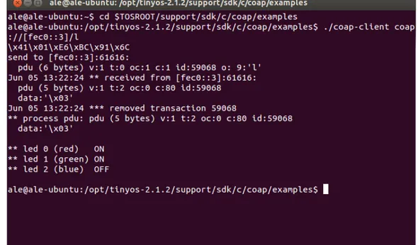
In order to test the system, within the CoapBlip library an ex-ample client application is provided (at /support/sdk/c/coap/examples). With this application, it is
possi-ble to send CoAP requests to the motes from the Linux Termi-nal. For example, the request for getting the leds' status would be:”./coap-client coap://[fec0::3]/l” [25]. In Figure 4.3 an output for this request is represented.
Figure 4.3: CoAP GET request example.
4.1
SensibleThings platform
The CoAP communication stack extends the Sensor and Actua-tor layer of the SensibleThings platform, which has already been described in paragraph 2.5.1. This platform enables multi-ple nodes to communicate and to exchange data over the Inter-net. This feature then has been used to connect multiple remote WSNs together and to build applications for managing the re-trieved data from various nodes.
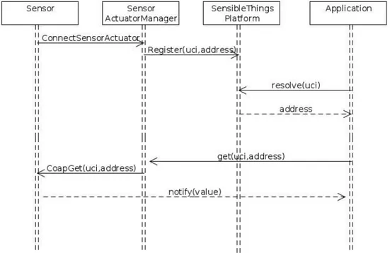
A component called SensorActuatorManager has been used in order to bind the CoAP stack with the SensibleThings platform. This component is included in the Sensor and Actuator layer and his main task is to manage the requests between the plat-form and this layer. It implements six methods:
• connectSensorActuator(): it is for connecting any
the sensor/actuator will be registered and available inside the platform.
• disconnectSensorActuator() and disconnectAllSenso-rActuators(): are called for disconnecting a specific
sen-sor and all the sensen-sors from the platform, respectively. • HandleGetEvent() and HandleSetEvent(): this method is
called from the platform, to forward a getEvent/setEvent to the sensors.
In Figure 4.4 the sequence of methods called within a GET re-quest between two remote nodes is shown.
Figure 4.4: GET request.
4.2
CoAP packet structure
A CoAP packet is formed by a 4 bytes binary header followed by an option field and a payload. The length of the message payload is implied by the datagram packet length. The structure of a CoAP packet is shown in Figure 4.5.
Figure 4.5: CoAP packet format. The fields within the packet header are:
Ver: Version, 2 bit unsigned integer. This value indicates the
version of CoAP protocol. To set this field correctly for the CoAPBlib library, 1 has to be set as its value. Other values are reserved for future versions.
T: Transaction type field, 2 bit unsigned integer. This field
indi-cates if this message is Confirmable (0), Non-confirmable (1), Acknowledgment (2) or Reset (3).
OC: Option count field, 4 bit unsigned integer. This field
indi-cates how many option headers follow the base headers. If set to 0 the payload (if any) immediately follows the base header.
Code: 8 bit unsigned integer. It indicates the Method or the
Re-sponse Code of a message. The method codes are reported in the following table:
The CoAPBlip library only allows get and put methods, how-ever. The values 40-225 are used for Response Codes. The CoAP stack developed in this thesis only uses the values 80 (HTTP code: 200 OK) and 160 (HTTP code: 400 Bad request).
Transaction ID: 16 bit unsigned integer. This value identifies
each CoAP transaction since this is a unique ID assigned by the source. The response message for each request must contain the
same transaction ID as the request message. This value must also be changed for each new request except when retransmit-ting a request.
CoAP messages may also include one or more header options in Type Length Format (TLV) and they have to appear in order of option type. The option types used in the CoAP stack were: URI path (for specifying the sensor URI within a sensor node, Type number: 9),Token (for sending the data payload in a PUT request, Type number: 11) and Content Type (which indicates the Internet media type of the token, Type number: 1). A delta encoding is used between each option header, with the Type identifier for each Option calculated as the sum of its Option Delta field and the Type identifier of the preceding Option in the message, if any, or zero otherwise. Each option header also includes a Length field, as represented in Figure 4.6.
Figure 4.6: Option field format.
Option delta: 4 bit unsigned integer. This field defines the
dif-ference between the option Type of this option and the previous one (or zero for the first option). In other words, the Type iden-tifier is calculated by simply summing the Option delta fields of this one and previous options.
Length: 4 bit unsigned integer. This field specifies the length of
the option payload.
Figure 4.7 shows a basic request sequence. A client makes a Confirmable GET request for the resource/temperature to the server with a Transaction ID of 1234. The request includes one URI-Path Option (delta 0 + 9 = 9) "temperature" of Len = 11. The corresponding Acknowledgment is of Code 200 OK and in-cludes a Payload of "22.3 C". The Transaction ID is 1234, thus the transaction is successfully completed. The response Con-tent type of 0 (text/plain) is assumed as there is no ConCon-tent type Option [26].
Figure 4.7: CoAP get transaction example.
4.3
CoapSensorActuator
CoapSensorActuator is responsible for the communication be-tween the platform and the sink of a WSN, through the CoAP protocol. Its main task is to create CoAP packets, send them to a mote and parse the response message.
It extends the SensorActuator abstract class and implements its two methods getValue() and setValue(), as shown in Figure 4.8. The constructor gets the IP address of the mote and the sensor UCI. At the end of the IP address the URI of the sensor also needs to be specified by the user.
Figure 4.8: CoapSensorActuator UML scheme.
getValue(): this method is called by the SensibleThings
plat-form every time a CoAP GET request has to be sent to a mote. It is a synchronized method because only one thread at a time can send a GET request to a mote. According to the CoAP pro-tocol standard, getValue creates a CoAP packet using the
cre-ateCoapGetMessage() method. Then it uses a DatagramSocket
to send the packet to the mote at the specific IP address set by the user. However, the number of the port cannot be chosen by the user, since CoAPBlip on TelosB motes always uses the de-fault port 61616 to receive the requests. If the request has been sent correctly, a response CoAP packet is received on the same socket. To parse the received packet, in order to extract the value of the sensor reading, the method readResult() is called. Since a response message can never be received from the mote, a timer of 4 seconds is set during the creation of the Datagram-Socket. If after that period of time the response has not been received, the lock on the SensorActuator object is released and a new GET request can be sent.
createCoapGetMessage(): this method builds a CoAP GET
message, according to what has been explained in paragraph 4.3.
![Figure 2.2: Representation of the first definition of IoT. Definition by [6]:“The semantic origin of the expression is composed by two words and concepts: Internet and Thing, where Internet can be defined as the world-wide network of interconnected compute](https://thumb-eu.123doks.com/thumbv2/123dokorg/7453094.101176/15.892.279.624.177.484/representation-definition-definition-expression-concepts-internet-internet-interconnected.webp)
![Figure 2.3: IoT application areas [8].](https://thumb-eu.123doks.com/thumbv2/123dokorg/7453094.101176/16.892.172.727.621.954/figure-iot-application-areas.webp)

![Figure 2.7: Specification and graphical depiction of the TimerM component [14].](https://thumb-eu.123doks.com/thumbv2/123dokorg/7453094.101176/24.892.234.666.816.1048/figure-specification-graphical-depiction-timerm-component.webp)
![Figure 2.11: Comparision of functional aspects of the OS [12].](https://thumb-eu.123doks.com/thumbv2/123dokorg/7453094.101176/28.892.206.686.627.880/figure-comparision-functional-aspects-os.webp)

![Figure 2.23: SenseWeb architecture [24].](https://thumb-eu.123doks.com/thumbv2/123dokorg/7453094.101176/42.892.259.646.171.517/figure-senseweb-architecture.webp)