Assessing Silicon Carbide ceramics and composites for energy-related
applications
Claudio Mingazzini, ENEA, Faenza (Ra), Italy [email protected] Matteo Scafè, ENEA, Faenza (Ra) Italy [email protected]
Antonio Rinaldi, ENEA, Casaccia, Rome, Italy [email protected]
Cedric Sauder, DEN-Service de Recherches Métallurgiques Appliquées, CEA, Université Paris-Saclay, F-91191, Gif-sur-Yvette, France [email protected]
Karsten Klemens Hansen, LiqTech Intern., Industriparken 22C DK-2750 Ballerup, Denmark [email protected]
James Braun, DEN-Service de Recherches Métallurgiques Appliquées, CEA, Université Paris-Saclay, F-91191, Gif-sur-Yvette, France [email protected]
Martin Steinbrueck, KIT, Karlsruhe Institute of Techn. Eggenstein-Leopoldshafen, Germany [email protected]
Abstract— Silicon carbide ceramics are really appreciated in energy applications, especially when extreme environments are involved. Their reliability and thermomechanical performances beyond 1000°C are higher than that of superalloys, therefore they may significantly contribute to the reduction of Critical Raw Materials use, which is a crucial point for sustainability issues. The examples discussed in the present paper are taken from European projects, in the field of nuclear energy (IV gen fission nuclear reactors) and renewable energy production (Concentrated Solar Power) and demonstrate a common approach based on optimizing and assessing the ceramic materials, considering current international standards, but also prenormative research and accelerated ageing tests in expected working environments. In this way, together with a simultaneous process implementation for the production of components in the size and geometry required for the applications, high target TRL (5-7) can be demonstrated, creating the
competencies, the methods and the results needed for subsequent industrialisation.
Keywords—Silicon carbide; SiCf/SiC composites; helium Gas- cooled Fast Reactor (GFR); silicon carbide; Concentrated Solar Power (CSP); Chemical Vapour Deposition (CVD); Chemical Vapour Infiltration (CVI) I. INTRODUCTION
Within FP7 MatISSE project (www.fp7-matisse.eu), SiCf/SiC composites were studied for fuel cladding, to be applied to generation IV GFR fission nuclear reactors. During the project (ended in November 2017), ceramic SiCf/SiC clad sections and hybrid ones (SiCf/SiC with a Ta liner, patents US2014153688A1 and FR20110057042 20110801) were
fabricated and assessed in relevant working conditions (ordinary operation T below 1000°C; impure helium flow rate at 90m/s; required gas tightness up to 8MPa; accidental condition up to 2200°C). Fabrication of nuclear grade SiCf/SiC clad sections was up to CEA applying their proprietary technologies. A thin tantalum liner (100 µm) ensures the cladding leak-tightness (necessary target for clads, to contain fission gases). Filament winding or braiding along with Chemical Vapour Infiltration (CVI) are employed for producing a first SiCf/SiC tube, which is (in the case of hybrid design) rectified to fit a metallic external liner, before
manufacturing another SiCf/SiC layer (up to 1 mm total thickness). Characterisation included: non-destructive ultrasonic testing of all samples produced; mechanical, leak- tightness and thermal properties evaluation of sandwich clads, stress-strain characterisation under bi-axial loading; leak- tightness characterization of SiCf/SiC sandwich up to 1000°C and 19MPa; thermal conductivity evaluations up to 1000°C; assessments of SiCf/SiC compatibility with impure He coolant (900-1600°C, 0.1 MPa performed at KIT) and corrosion kinetics studies (900°C, 7 MPa and 90 m/s impure He flow performed in CVR (Cz), exploiting a specifically developed high temperature helium loop, employing microtomography before and after the ageing tests). The research was partly funded by the Euratom FP7/2007-2013, grant agreement No. 604862 (MatISSE project), and in the framework of the EERA- JPNM. This 4-year project ended at the end of October 2017.
Within 4-years H2020 NEXTOWER project (www.h2020- nextower.eu) porous SiC is being studied for the production of ceramic solar receivers, to produce hot air, for efficient (electrical and thermal) power generation. Expected working temperature is up to 1000°C, with frequent thermal shocks. Materials requirements are linked to suitable mechanical and thermomechanical properties, high thermal
conductivity, high absorption of the solar spectrum and low emissivity. Accelerated ageing is studied using a solar furnace, and ceramic receivers fabrication will allow (by the end of 2020) TRL7 demonstration of the technology. The ceramic receivers will be obtained by joining a SiC honeycomb tiles with SiC cups, by gas sintering at temperature higher than 2500°C. This all-SiC solution avoids any possible thermal expansion mismatch, and is the most promising for maintenance-free operation up to 20 years. NEXTOWER project exploits the technologies already applied for the production of SiC membranes for water and air filtration (Diesel particulate filters). Low emissivity treatments (coatings and micropatterning) and Chemical Vapor Infiltration on porous SiC are also being studied, at low TRL, to increase efficiency (thermal conductivity and surface optical abpsortion and emission properties).
The present paper will discuss a selection of experimental methods and results, in order to show the assessment approach on SiC based solutions. SiC materials still represent the best thermomechanical ones for extreme environments, being comparatively cheap, widely applicable and sustainable, both from the economic and environmental point of view. SiC Fibers are currently still too expensive for most applications except nuclear ones, however their production process is currently being scaled up for aeronautical
applications, so production costs limitations might be overcome in the near future.
II. SIC/SIC COMPOSITES FOR GFR FUEL CLADDIND A. Partnership and Matisse project activities outline
Results discussed into the present paper are taken from tasks 3.1 to 3.3 of Matisse WP3, the workpackage devoted to ceramic composites for nuclear fission applications, which involves the partner specified in column 1 of table 1, with a brief task description in column 2. Besides CEA, KIT and ENEA, WP3 activity on GFR involved University of Oxford (Uk), University of Manchester (Uk), CVRez (Czech Republic), Politecnico of Turin (Italy) and PSI (Switzerland).
Task 3.1: SiCf/SiC clad sections for the characterization and qualification were produced by CEA with maximum length 190 mm and different external surface finish, applying CEA proprietary technologies. These clads are based on a 2D texture of 3 successive layers, 1 layer of filament winding on which 2 layers of 2D braiding are added. Pyrocarbon coating is infiltrated through the texture by CVI (prior to SiC
infiltration) with the objective of 30-50nm thickness. SiC infiltration is made by CVI in 2 steps. 3 different levels of external surface roughness were produced (Fig. 1): level 1 (Ra about 50 µm, no grinding), level 2 (Ra about 10 µm) and level 3 (Ra about 1-3 µm). Pre-damaged samples were generated by interrupted mechanical tensile tests at 0.1%, 0.3% and 0.5% longitudinal strain. Since SiCf/SiC composites are not gastight upon their linear elastic domain, CEA patented a new concept [1] to reach gas-tightness of the SiCf/SiC cladding up to ultimate failure of the material. It is based on the insertion of a thin (0.1 mm) tantalum metallic liner between two layer of SiCf/SiC. Mechanical resistance of cladding is based on the SiCf/SiC parts. The role of the metallic liner is only to guarantee the gas-tightness of cladding up to the rupture. Quality inspection via non-destructive testing (NDT) had been performed on almost all clads, before the characterization activities, to provide the samples with a report about their defect/flaw characteristics. After a preliminary study to compare NDT approaches, ultrasonic scanning and X-ray tomography were chosen. Ultrasonic scanning may evidence not only macroscopic defects (delamination, large voids) but also to microscopic features quickly and easily.
Task 3.2: the innovative SiC sandwich concept is illustrated in Fig. 3. The mechanical typical behaviour comprises a reduced initial domain of elasticity, followed by a curved region resulting from matrix cracking and associated fiber debonding and then a slight curvature preceding ultimate failure at strains in the 0.8-1.1% range, depending the roughness level. On SiCf/SiC sandwich type, after failure of the SiC tubular structures, the tantalum liner still keeps its integrity, thanks to the weak link with SiC. Predamaging allows path for the diffusion of Oxygen up to PyC interphase which is less resistant than SiC in oxidizing
atmosphere, so it is a way of accelerating the ageing. However the experimental tests demonstrated that even in this condition, no mechanical degradation occurs upon ageing. Bi-axial loading tests were
performed to derive micromechanically-based modelling, in association with tomography and Digital Volume Correlation. Feasibility evaluation of using in situ high resolution X-ray tomography during mechanical tests has also been performed (Oxford & Manchester Universities). Leak tightness
characterization of SiCf/SiC sandwich type was tested up to 1000°C, using a new device developed in CEA, giving really good results.
Regarding thermal conductivity up to 1000°C, PSI developed an apparatus (based on the Anter method) suitable for testing SiCf/SiC (normal and sandwich type) clad sections. CEA focused on the development of another system, based on a flash method, that has been implemented to estimate the apparent radial thermal diffusivity. The transverse thermal conductivity of the latest generation of SiCf/SiC composites is confirmed between 25 and 35 W.m-1.K-1. However, thermal diffusivity decreases with the progressive damage of the composites due to the matrix micro-cracking network growth and to the fiber/matrix debonding.
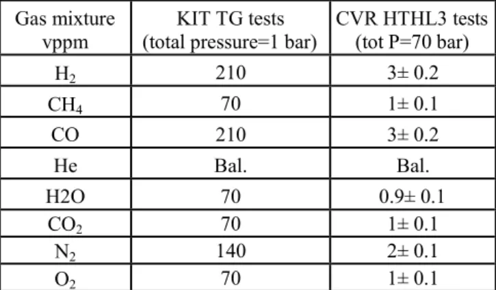
Tasks 3.3 was about the assessments of SiCf/SiC and sandwich clad compatibility with expected working environment, which (in GFR applications) is represented by nearly pure high pressure, high temperature and high flowing rate helium. Although it may not appear a challenging environment for SiC, SiC durability at high T is higher at high oxidants levels than at lower ones, due to active oxidation phenomena. NNL identified the most suitable coolant reference chemistry (table 2, [3]), which was the target for all the ageing tests (by KIT and CVR), by keeping fixed the partial pressures of the active species (in term of volume part per million, vppm).
Table 1. Matisse WP3 partnership and brief outline Participants Task descriptions
• Task 3.1:CEA,
ENEA
SiCf/SiC tubes fabrication (normal and sandwich type), quality
assessments and supply
• Task 3.2:PSI,
CEA,POLITO,
UOXF, UNIMAN
Mechanical, leak tightness and thermal properties of SiCf/SiC clads (normal and sandwich type) and microstructure correlations
• Task 3.3:KIT,
NNL,CVR,
POLITO
Assessments of SiCf/SiC clads (normal and sandwich type) into the expected working environment
Fig. 1. SiCf/SiC three levels of surface roughness.
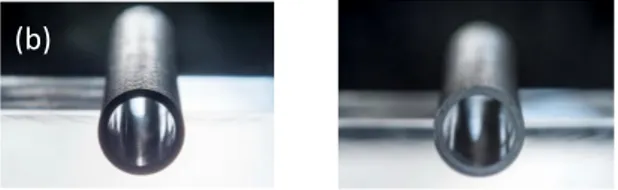
Fig. 2. Photographs of SiCf/SiC clad sections: normal (a) and sandwich type (b). External diameter 10mm.
Fig. 3. SiC/SiC sandwich patented gastight cladding for GFR
Strain (%) 0 50 100 150 200 250 300 0 0,2 0,4 0,6 0,8 1 SiC/SiC composite Ta layer Stress (MPa) Deformation (%) Gastight range of classical SiC/SiC Elastic limit (σ E~80MPa - εE~0.04%) Usual nominal working
limit of fuel cladding
Gastight range covered by the sandwich patented solution
(a) Level 1 (b) Level 2 (c) Level 3
KIT studied corrosion kinetics of SiCf/SiC in this reference chemistry by thermo-gravimetric analysis at atmospheric pressure, between 900 °C and 1600 °C, reproducing the same partial pressures expected at the working pressure (70 atm). SiC protective passive oxidation was observed up to 1200°C. Starting from 1300°C active oxidation, i.e. with mass loss due to the volatilization of SiC, took place. Sandwich type SiCf/SiC clad samples were also tested, but measures were negatively affected by tantalum oxidation at non-protected edge regions of the samples. CVD protection proved unable to protect these regions. Ageing experiments in expected working parameters took place in CVR using High Temperature Furnace (HTF, working at 760, 900°C; duration 1000h, 0.5MPa) and, during the second half of 2017, High Temperature Loop (HTHL-3, working at 900°C, 7MPa, He flow, 90m/s). Although HTHL3 realization required much more time than expected and experiments could only be limited to seven clad sections 60 mm length, the results are encouraging, meaning that in none case ageing produced detectable microstructural changes or
mechanical degradation. In High Temperature Helium Loop (HTHL3), the simultaneous effect of all expected parameters (90m/s He flow, 7 MPa, 900°C, were successfully tested for 500h), except for the oxygen amount, which couldn’t be set at a value below 24vppm (instead of 1 vppm, which would had fit expected reference chemistry).
III. TENSILE TESTS ON SICF/SIC CLAD SECTIONS
Room temperature tensile tests were performed employing an Instron 4204 device (equipped with a 25kN load cell). Uniaxial tension tests were performed at room temperature on 60mm length samples at a constant rate (50 µm/min). Composite ends are affixed within metallic supports using a structural glue. The supports were gripped into the testing machine. Composites longitudinal deformations were measured using an Instron 2620-603 extensometer (range ±1mm) with a 25mm gauge length. Diametral deformations were measured using an MTS 634.19f20 extensometer (range ±1mm). Acoustic emission was recorded during the tests. Signals were analyzed by the number of counts for a 50 dB preset amplitude threshold. The fracture surface of the specimens was examined after the tests using the optical microscopy and Scanning Electron Microscopy (SEM). Figure 4 illustrates the tensile test equipment and mounting of tubular SiCf/SiC (without diametral extensometer). At least 6 tensile tests were made for each type of SiCf/SiC clad section (normal and sandwich type) and surface roughness. The typical stress–strain curves on SiC/SiC normal type are shown in Fig. 5, and reflect the conventional composite behaviour that has been previously observed on SiCf/SiC composites reinforced by Hi-Nicalon S fibers [3]. They are markedly nonlinear, coupled with the following typical features: (a) an initial domain of elasticity (no acoustic emission signal); (b) a curved region resulting from matrix cracking and associated fiber debonding; (c) a slight curvature preceding the maximum force, indicating fiber breaks, and ultimate failure at strains in the 0.8-1.1% range depending the roughness level of sample. This ultimate tensile strain is higher than the strain to failure of HNS fibers. This is the consequence of the filament winding and braiding angle (45°). The onset of matrix cracking was identified by the first acoustic emission signals, at ~ 0.04% longitudinal strain. Upon this value, no saturation of Acoustic Emission (AE) signal is observed until ultimate failure. Matrix cracks spacing were measure after several interrupted mechanical tensile tests for different level of strain (0.3%, 0.5%, 0.7% and after failure) by optical microscopy of polished longitudinal sections. The mechanical characteristics extracted from tensile tests are summarised in Table III. Elastic domain (delimited by σl and associated to an elongation of about 0.04%) is similar whatever the surface roughness level of SiCf/SiC samples. Young modulus seems to be a little higher for smooth samples (level 3) but the difference remains low. The main difference between as manufactured (level 1) and level 2 and 3 roughness samples is the lower values of strength and strain to failure for smoother samples (level 2 and 3). The dispersion is also greater for level 2 and 3 samples. This is probably due to a small degradation of the 3rd layer of the texture (2D braiding) during external grinding process. Nevertheless, this reduction is small (~10%).
Table 2. HE IMPURITY REFERENCE CHEMISTRY RELEVANT TO GFR
Gas mixture
vppm (total pressure=1 bar)KIT TG tests CVR HTHL3 tests (tot P=70 bar)
H2 210 3± 0.2 CH4 70 1± 0.1 CO 210 3± 0.2 He Bal. Bal. H2O 70 0.9± 0.1 CO2 70 1± 0.1 N2 140 2± 0.1 O2 70 1± 0.1
Fig. 4. Typical mounting for a tubular tensile test on SiC/SiC
Fig. 5. Typical tensile stress–strain curves obtained for SiCf/SiC clad sections with different surface roughness.
0,0 0,2 0,4 0,6 0,8 1,0 1,2 0 50 100 150 200 250 300 -0,20 0,00 0,20 0,40 0,60 0,80 1,00 1,20
Ac
ou
st
ic
Em
iss
io
n (
No
rm
al
ize
d s
ig
na
l)
St
re
ss
(M
Pa
)
Strain (%) SiCL1 longitudinal SiCL2 Longitudinal SiCL3 longitudinal SiCL1 diametral SiCL2 diametral SiCL3 diametral SiCL1 AE SiCL2 AE SiCL3 AEThe typical stress–strain curves on SiC/SiC sandwich type are shown in Fig. 6. Failure of the clads is not complete at the maximum reached stress, and beyond this value (Fig. 7) the tantalum liner still supports the mechanical stress. This demonstrates the interest of this sandwich concept that keep the tantalum integrity even after the failure of SiCf/SiC structure. This is only possible thanks the high ductility of tantalum and the weak link between SiCf/SiC and tantalum.
IV. PRESSURIZATION TESTS ON SIC/SIC CLAD SECTIONS
SiCf/SiC sandwich clads has to guarantee gas tightness up for continuous operation at 1000°C and 8 MPa pressure. Test were performed up to 19MPa exploiting a CEA developed testing facility shown in figure 8. A Ta gas pipe was welded on the Ta liner, allowing the introduction of helium inside the CMC tube, while simultaneous heating into a furnace. Tests demonstrated that the sandwich concept is valuable to
withstand high gas pressure and temperature, since no rupture was observed in the effective length of the sandwich clad sections, although leakages took places at the junction, due to the difficulties of welding tantalum pipes with a factor ten difference in thickness.
V. SIC/SIC CHEMICAL COMPATIBILITY EVALUATIONS
KIT tests showed that SiCf/SiC clads are compatible with impurity reference chemistry and no active oxidation (the phenomenon that may consume SiC by producing volatile SiO species) occurs up to, at least 1200°C, which is fair beyond expected working conditions [4].
VI. EXTRUDED POROUS SIC FOR CSP CERAMIC RECEIVERS
Besides high durability in harsh environments, SiC has another unique property which makes it a unique material for energy application, that is its absorption of solar spectrum. Ceramic solar receivers are the basis of newest generation CSP (Concentrated Solar Power) systems, that it was demonstrated can convert into usable energy a much higher portion of solar energy than photovoltaic systems. Project H2020
“Nextower” was developed as a crosscutting application of nuclear technologies, applied to renewable energy production. From the nuclear field it were taken two concepts: (1) the use of liquid lead as a heat storage/transport fluid, to go beyond melted salts limitations and (2) the use of optimised SiC materials for Ceramic Solar Receivers to produce hot air at T beyond 900°C. In this article we will discuss briefly about SiC optimisation. The main requirements of materials for CSP (see figure 9) are (a) high durability and, in particular, tolerance to oxidant environments at 1000°C and to fast and frequent thermal shocks; (b) high thermal conductivity, combined with high absorption of the solar spectrum and low emissivity: (c)
technologies to produce complex shapes at low prices. Although SiC/SiC could meet all technical
performance targets, it is certainly not cheap. Best quality SiC fiber costs around 10 € per gram, a price per weight that is around € per gram when we are considering a SiC/SiC CVI densified component. That is not the kind of production costs that can be tolerated for a Ceramic Solar Receiver. Monolithic SiC could also work as a material (meeting both requirement a and b), although it is still too expensive produce complex shape geometries. The only type of SiC which seemed promising to be studied for CSP is porous SiC, that is currently produced at low price by extrusion dewaxing and gas sintering of “SiC compounds” (that is the combinations of SiC powders and polymers). Since porosity reduces Young’s module according to the lever rule, the thermal shock resistance is increase to a level that makes the component tolerant to thermal gradients up to 70°/cm and thermal shock of beyond 500°C in a few seconds. In figure 10 it is shown a scheme of a solar ceramic receiver works also showing the expected working parameters and how hot air is produced by irradiation. The state of the art of high temperature CSP (after SOLAIR FP7 project) uses a ceramic tile less than 200x200x20 mm, in the form of a honeycomb or an engineered rapid prototyped grid, joined to a ceramic cup. These components are distributed in an array and connected to a collector system for the hot air. These first generation receivers generally “failed” too early to make the
TABLE3RESULTS (AND STD DEV) OF TENSILE TESTS ON SIC/SIC SiC/SiC clad type Young’s mod (GPa) Strength
(MPa) Failure strain (%)
σl
(MPa) SiCL1 279 (±7) 289 (±1) 1.12 (±0.04) 92 (±6)
SICL2 273(±11) 264(±29) 0.95 (±0.13) 97 (±6)
SiCL3 300 (±14) 265 (±8) 0.95 ±0.03) 98 (±2)
Fig. 6. Typical tensile stress–strain curves for SiCf/SiC sandwich clad sections up to maximum reached stress.
Fig. 7. Typical tensile stress–strain curves obtained for a sandwich clad section (beyond the maximum stress value).
TABLE 4.RESULTS OF TENSILE TESTS ON SIC/SIC SANDWICH TYPE
Sandwich
clad type Young’s mod (GPa) Strength (MPa) Failure strain (%)
σl (MPa) SiCL1 286 (±21) 247 (±7) 0.84 (±0.05) 100 (±7) SICL2 311(±22) 221 (±5) 0.75 (±0.06) 124 (±12) SiCL3 316 (±16) 243 (±3) 0.80 (±0.03) 138 (±29) 0,0 0,2 0,4 0,6 0,8 1,0 1,2 0 50 100 150 200 250 300 -0,20 0,00 0,20 0,40 0,60 0,80 1,00 1,20 A co us ti c Em iss io n (N or m al iz ed si gn al ) St re ss (M Pa ) Strain (%) SandL1 longitudinal SandL2 Longitudinal SandL3 longitudinal SandL1 diametral SandL2 diametral SandL3 diametral SandL1 AE SandL2 AE SandL3 AE 0,0 0,2 0,4 0,6 0,8 1,0 0 50 100 150 200 250 300 -0,2 0,0 0,2 0,4 0,6 0,8 1,0 A co us ti c Em is si on (n or m al iz ed s ig na l) St re ss (M Pa ) Strain (%) Longitudinal strain Diametral strain Acoustic emission
Fig.8. High T and P SiC/SiC clad section permeation device.
Fig.9. Schematic representation of a high T CSP system.
Fig.10. Schematic representation of ceramic solar receiver.
RE
CIC
UL
AT
ING
FL
UX
AMBIENT AIR HOT AIR SOLAR FLUXsystem interesting for industrialisation, but improved quality and highly standardised SiC materials may certainly contribute substantially to overcome these limitations. In order to optimise thermal shock
resistance, gas phase sintering made recently quite significantly improvements, both to the bulk properties and the quality of SiC-SiC joining, which may be achieved at 2200°C using exclusively pure SiC. After almost 18 months of optimisation, the more promising microstructure of porous SiC is that shown in figure 11, which is a 43 volume% open porosity. Although this microstucture ensures a apparently satisfying thermal shock resistance (although thermal cycle ageing in solar furnace are still ongoing) the open porosity makes it difficult to apply low emissivity treatments (which in Nextower proposal will be studied by developing sol-gel and surface micropatterning). So another contribution to CSP from the nuclear technology came from the CVD/CVI process, which is certainly quite time consuming and expensive when aims at densification, but can represent an affordable step of production process when oriented to simply seal a SiC surface, before surface treatments to optimise emissivity and thermal diffusivity, which have fundamental role in determining CSP efficiency.
VII. POROUS SIC THERMOMECHANICAL QUALIFICATION
Porous SiC was produced by LiqTech Intl. (Denmark), partner of project Nextower, applying their
proprietary pure-SiC gas-phase sintering technology. Parameters were optimised in order to optimise high T strength at 1000°C. 4-Point Bending Test were performed at room temperature (23.5 °C) by using MTS electro-hydraulic testing machine (outer span 40 mm, inner span 20 mm, displacement rate = 0.6 mm/min). On the same samples, Young’s modulus was also determined by Impulse Excitation Method by using Grindosonic MK5 measurement system. Results on the optimised material (referred as “LiqStd” from now on, being a SiC solution quite similar to the one that LiqTech produce for Diesel Particulate filters) are summarised in table V. Regarding the effect of temperature on LiqStd SiC MOR values, fig. 11 shows the evolution of the typical stress strain curve upon temperature increase. Another test which was made was a preliminary thermal ageing consisting in ten thermal shocks, from 1000°C to room temperature, which resulted not to decrease significantly the strength and Young’s modulus. The mean MOR and Young’s modulus values at the considered temperatures and the data scatter of these measurements are shown in figure 13 and 14. These measurements will be repeated after thermal ageing in solar furnace, exactly simulating the expected working environments, both on the material produced as a slab (50x50x5 mm) and, later in the project, on SiC components.
VIII. CONCLUSION
Material optimisation associated with qualification according to international standards and ageing tests in simulated working environments associated with modelling and iterative optimisation appears the proper way to exploit advanced materials and make them an enabling technology to demonstrate, at TRL up to 7, to improve efficiency and safety of energy production, both in the energy field.
IX. REFERENCES
[1] Maxime Zabiego, Cédric SAUDER, Christophe Lorrette, Philippe Guedeney “Multilayer tube in ceramic matrix composite material. resulting nuclear fuel cladding and associated manufacturing processes”. US2014153688 (A1).
[2] C. Sauder, “Chapter 22 - CERAMIC MATRIX COMPOSITES: NUCLEAR APPLICATIONS”, Wiley 2015, pp.609-649.
[3] K. Fitzgerald und D. Shepherd, “Review of SiCf/SiC corrosion, erosion and erosion-corrosion in high temperature helium relevant to GFR conditions”, Journal of Nuclear Materials, 498, September 2017. [4] V.Angelici Avincola, K. Fitsgerald, D. Sheperd, M Steinbruck, “High-temperature tests of silicon carbide composite cladding under GFR conditions”, Energy Procedia, 127 (2017) 320-328.
Fig.11. Microstructure of 43% vol open porous SiC.
Fig.13. Effect of Temperature on MOR of “LiqStd” SiC.
Fig.14. Effect of Temperature on Young’s modules of “LiqStd” SiC.
This work was partly funded by MatISSe Collaborative Project “Materials' Innovations for Safe and Sustainable Nuclear” (European Commission Seventh Framework Programme Grant 604862, FP7-Fission-2013), and project NEXTOWER (European Commission H2020, Grant 721045)