Kinematic performance enhancement of
wheelchair-mounted robotic arm by adding a linear drive
Alberto BorboniMechanical and Industrial Engineering
Department Universita degli Studi
di Brescia Brescia, Italy [email protected] Marco Maddalena School of Mechanical Engineering University of Birmingham Birmingham, UK [email protected] Alireza Rastegarpanah School of Mechanical Engineering University of Birmingham Birmingham, UK [email protected]. ac.uk Mozafar Saadat School of Mechanical Engineering University of Birmingham Birmingham, UK [email protected] Francesco Aggogeri Mechanical and Industrial Engineering Department Universita degli Studi
di Brescia Brescia, Italy francesco.aggogeri@u
nibs.it
Abstract —Wheelchair-Mounted Robotic Arms have been used to help impaired people to reach objects and perform essential activities in an autonomous way. Different available models are presented in this paper and a simple design is proposed to improve the kinematic performances of the integrated system in order to allow the user to increase its capability of interaction with home environment. To this end, a linear drive has been added to the Raptor model in order to move along the wheelchair. The benefit of the proposed development has been proved with a kinematic performance assessment procedure, which has analyzed critical points in the 3D space, providing 26% increase in performance with respect to the existing solution.
Keywords— disability; wheelchair; manipulator; kinematics; robotic arm;
I. INTRODUCTION
Modern society is facing the issue of progressive population aging, so huge number of people with various disabilities rely on external help in order to do their basic daily activities.
In recent years, many research groups have focused on robotic applications for elderly and disabled people care, with the aim of improving life quality and to give the possibility of carrying out several tasks autonomously [1-5]. In particular, people with severe walking capability would require an integration between a manipulator arm and an electric wheelchair in order to interact with the environment and to grasp objects. Both commercially available products and those offered by research centers offer several models of manipulators integrated with wheelchair and provided with user interface. In section II different existing solutions are presented and compared according to a number of key features.
The aim of this paper is to increase the workspace of a robot by adding a linear actuator along wheelchair side of a pre-existing configuration, presented in [6]. Two different
manipulators were added to a wheelchair and the kinematic performance of both manipulators was compared in some application-oriented situations, defined as Activities of Daily Living (ADL). In this paper, Raptor manipulator [6] has been chosen among the existing robots and its kinematics are analyzed in section III. Furthermore, a proposed configuration enhancement is addressed. Sections IV presents the kinematic analysis of the manipulators. In Section V, variations between two different manipulators are investigated based on ADL activities. In section VI, the results of this comparison are presented.
A. Commercially Available Manipulators
During the past twenty years several manipulators have been brought to the market, adapting their features to final users’ needs and proving their benefit in performing the required tasks.
Raptor is a manipulator arm for wheelchair applications traded by Phybotics since 2008 [6]. It has 4 Degrees of Freedom (DoF) which is equipped with two fingers for grasping applications, being built with polymeric material with a weight of 8 kg. Raptor can be controlled by a joystick/keyboard or with a Sip and Puff technology (SNP) which allows the user to handle the manipulator by blowing and inhaling air through a tube. Pittsburgh University have had different studies on spine-injured patients, wherethe effectiveness of the manipulator was proved in a range of activities such as pouring water in a glass or grasping various objects [7].
Another company called Exact Dynamics started to develop a manipulator in the ‘90s. The aim was to build a device to be placed on a wheelchair and to be controlled by patients with upper limb disability [8, 9]. Manus is a 6DoF robot with a gripper as an end-effector. The Manus project led to the last model named iARM [9], a 6DoF robot with a weight of 9 kg which used the same battery as the wheelchair. It is able to
reach objects within a distance of 90cm with a roughly spherical workspace which can lift a load of 1.5 kg. This model can be controlled by a keyboard, joystick or even a single button.
Jaco is another 6DoF manipulator made by Canadian company Kinova and has been traded since 2009 [10]. This product intended to be used by patients with upper limb disabilities, usually due to muscular dystrophy, amyotrophic lateral sclerosis, spine injuries, multiple sclerosis or other neurological disorders. The main advantages of the robot are: its light weight property (5 kg), ease of use, good grasping capabilities due to three-fingered hand, and software programmability. The main drawback is its high price; moreover the user needs a minimum level of comprehension and a sufficient visual capability in order to exploit all Jaco functions.
B. Prototypes Proposed by Different Research Groups
Beside industrial products, various prototypes of wheelchair-mounted robotic arms have been presented by research groups around the world.
Korea Advanced Institute of Science and Technology (KAIST) designed two 6DoF manipulators, KARES I [11] and KARES II [7]. KARES I can be manually controlled by a keyboard or voice, while the successor KARES II can be driven by a vision system, a sensor glove, or through processing electromyographic (EMG) signals. The main objective of this model is allowing the user to carry out four tasks autonomously; grasping and drinking from a cup, grasping a pen from the floor, turning on and off a wall switch.
A 7DoF manipulator, FRIEND II has been developed in 2007 by the Automation Institute of University of Bremen [13]. FRIEND I, the previous version of Friend II, has a Brain-Computer Interface that is able to read signals through encephalography, so the user would be able to perform actions without using hands [13].
A robot model called WMRA I, followed by WMRA II, has been developed by University of South Florida [14]. WMRA II is a 9DOF Robot that can be controlled by different interfaces.
An assistive robot called Weston has been developed by the
(A)
(B)
(C)
FIGURE I-(A)3DMODEL OF RAPTOR,(B) THE WHEELCHAIR-MOUNTED
SYSTEM WITH REFERENCE FRAMES [6],(C) THE CAD MODEL OF PROPOSED
SYSTEM WITH ADDITIONAL WHEELCHAIR SIDE-MOUNTED LINEAR DRIVE
Bath institute of medical engineering [15]. It was designed in order to maximize the manipulation span on the horizontal plane using a SCARA robot. The robot has five motors on its upper arm; a motor for vertical regulation and a motor for the gripper which is controlled by a joystick and a visual human-machine interface. Due to its configuration, Weston has larger size than other wheelchair-mounted robots, but it has a larger workspace with capability of getting closer to tables and desks, thanks to its rear-side mounting position [15].
Another wheelchair-mounted robot called Asimov has been designed by Lund University, Sweden [16]. It has 8 degrees of freedom developed exploiting a modular structure; it is actuated by motors positioned on single modules and manually controlled by a joystick. The choice of modular solution has allowed placing the robot either in front, on the side, or in the back of the wheelchair.
C. Brief Models Comparison
Various control interfaces have been utilized in different models, however joystick is provided in most cases as a basic input device. All mentioned commercial robots were powered with 24V, so that they may be powered directly by the wheelchair battery, without adding any extra weight. There is an inverse proportional relationship between the price and weight of the system; the price increases as weight decreases.
Jaco and iARM have roughly the same sphere workspace with 90cm radius. Both have payload capability of 1.5 kg, which allows to lift small objects.
In all cases, the workspace of the robot is determined by the robot base location once the wheelchair brakes. This phenomenon led to the selection of the front side of the wheelchair as the robot base location in order to reach objects far from the wheelchair. It further gave the user the capability of observing the effect of the commands to the rebot. Hence the whole robot movement takes place in front of the user. However, this choice is not always successful; as it would make it impossible for the user to get close enough to tables and desks. This problem could be resolved if the manipulator slided along the wheelchair side.
II. KINEMATICS ANALYSIS OF THE MANIPULATOR In order to increase the reachability of the robot, a linear drive was added to the aforementioned Raptor model (Figure I-A) to move the manipulator along the wheelchair. The 4 DoF allows the manipulator to reach and grasp objects using a gripper.
The workspace of the manipulator will be increased by adding an extra degree of freedom (Figure I-C), although it increases the cost of the system. Adding a side mounted linear drive would not affect wheelchair’s agility, which is an advantage of the system.
Figure I-B illustrates the reference systems on the links of Raptor. The corresponding Denavit-Hartenberg Parameters for Raptor have been addressed in [6]. In this study, , and have been defined as revolute joints angles around , and axes. The fourth degree of freedom has been assumed to be zero ( = 0),as we are interested in evaluating the workspace in Cartesian coordinate system.
The following matrix describes the homogeneous transformation from the reference system located on the wheelchair (user reference system, with axes , and ) and the one located on the end-effector (gripper reference system, with axes , and ):
=
0 0 0 1
(1) The position of the end-effector has been illustrated by the
following equation: =
46.7 − 46.7 − 16 − 68.6
−46.7 − 34.2
46.7 + 46.7 − 41 + 68.6 (2) Equation 2 describes the end-effector position with respect to the wheelchair reference system and matrix describes the rotation of axes , and with respect to axes , and . (Note: abbreviations = and = have been used.)
Joint velocity (q) and end-effector Cartesian velocity (v) are defined by Equation 3:
= 1 2 3
, = (3)
Equation 4 describes the Jacobian matrix J, such that v = : ( ) = 1 2 3 1 2 3 1 2 3 (4)
And decoupled Jacobian matrix has been presented in equations 5, 6 and 7: = −46.7 − 46.7 − 68.6 0 46.7 − 46.7 − 68.6 (5) = 46.7 46.7 46.7 (6) = −46.7 − 46.7 46.7 −46.7 + 46.7 (7)
The Jacobian matrix is used in the kinematic performance assessment. In the configuration with additional linear actuator (Figure I-C), the located base coordinate reference on the wheelchair can be displaced along the axis, in order to achieve a better performance.
III. MANUPULABILITY ANALYSIS
The criterion for evaluating the kinematic performance of the manipulator arm configuration was the manipulability ellipsoid volume as defined by Yoshikawa [17]. Manipulability has been defined as the possibility to achieve the maximum end-effector velocity with respect to the absolute values of the joints velocities, which is presented by equation 8:
‖ ‖2 = = ( ) ( ) (8) If ‖q‖ = 1, then the achievable values of v belong to an ellipsoid; the length of main axes are equal to the square roots of eigenvalues of the matrix J J [17]. In order to evaluate the manipulability, the volume of the ellipsoid was considered, which is proportional to the product of the square roots of the eigenvalues of matrix J J. From basic linear algebra it is deduced that such product is equal to the square root of the determinant of the same matrix:
( ) = det ( ) ( ) = |det ( ( ))| (9) Therefore, given an end-effector position, the joint variables ( ) were computed by inverse kinematics, then the manipulability value was obtained simply as the absolute value of the determinant of the Jacobian matrix calculated at .
The performance factor has been calculated based on selected 3-D space points which are related to typical situations that the user can run into. In order to evaluate the robot capability to reach objects located at different heights with respect to the floor, the space was analyzed in horizontal planes (x-y) setting the value for z with respect to the floor as follows:
• Small objects on the floor: 5cm (-73.9 cm) • Larger light objects on the floor: 23 cm (-55.9 cm) • Height of electric socket: 46 cm (-32.9 cm) • Low coffee table: 66 cm (-12.9 cm)
• Height of standard table and door knob: 79 cm (0.1 cm) • Kitchen counter top: 97 cm (18.1 cm)
• Wall-mounted light switch: 127 cm (48.1 cm) • Low shelf above kitchen counter top 142 cm (63.1 cm) The values in parenthesis are the z-axis height with respect to the user coordinate system whose origin is located at 78.9 cm above the floor. Manipulability Index was evaluated for various space points according to different hypothetical object positions around the wheelchair. In the next section, the manipulability index have been calculated for the points located at x = 70cm (in front of the wheelchair) as an example.
The final performance index is the normalized manipulability (n) which is the ratio of manipulability value at the point over the maximum manipulability value throughout all the workspace; such index value is between 0 and 1 (in percentage from 0% to 100%).
In order to achieve a better visualization for the normalized manipulability index of the point’s grids, the following expressions have been used in [6] and are shown in Figure II:
81 - 100% Excellent 61 - 80% Very Good 41 - 60% Good 21 - 40% Limited 01 - 20% Very Limited > 1% Undetermined
FIGURE II. REPRESENTATION OF THE MANIPULABILITY MEASURE [6]
IV. ANALYSIS OF DIFFERENT CONFIGURATIONS OF RAPTOR
A. Raptor without Linear Drive
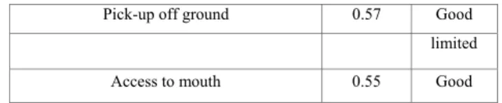
In Table I, the effectiveness of fixed Raptor has been shown. For any ADL, the average normalized manipulability index of all possible wheelchair orientations that could achieve the task and qualitative evaluation have been presented in studies [6, 18, 19].
TABLE I. QUALITATIVE SUMMARY OF RAPTOR EFFECTIVENESS
Pick-up off ground 0.57 Good
Coffee table 0.55 Good
Door knob 0.59 Good
Kitchen countertop 0.54 Good
Light switch 0.35 Limited
Low kitchen shelf 0.05 Very
Pick-up off ground 0.57 Good
limited
Access to mouth 0.55 Good
The normalized manipulability index was generally good, except for access to low kitchen shelf. The manipulator capability to reach such position is very limited. The score was not satisfying for the Light switch.
B. Raptor with Linear Drive
Manipulability index has been assessed with additional linear actuator configuration. The linear actuator was located on wheelchair side, allowing Raptor base to slide 20.32 cm back and forth along X axis. It was used in order to enlarge the workspace and to allow the user to get closer to tables or desks.
The span [-20.32 20.32] is divided into 1000 points, and then the manipulability index G was computed taking the highest value among the obtained points as origin of the user reference system (Figure I-B).
FIGURE III. MANIPULABILITY INDEX ON Y-Z PLANE X =70 CM
Table II illustrates the comparison of manipulability index between two configurations in the y-z plane at x = 70 cm. For end-effector position (x, y, z) the following data are reported:
• n shows the normalized manipulability index in fixed robot configuration;
• θ , θ , θ represent the joint angles (in radians) corresponding to max manipulability index in additional linear actuator configuration;
• G represents the manipulability index in additional linear actuator configuration;
• n represents the normalized manipulability index in additional linear actuator configuration;
• h represents the Raptor`s base displacement along X axis where max manipulability index was achieved with additional linear actuator configuration.
Figure III reports the manipulability index evaluation at the points located on the same vertical plane in both configurations. If the new configuration made an improvement on a point, such point has been represented using color, otherwise it has been represented using gray.
TABLEII. MANIPULABILITY INDEX COMPARISON AT X =70 CM.
OFF-WORKSPACE (OW) ILLUSTRATE THE POINT WHICH DOESN`T BELONG TO RAPTOR WORKSPACE FOR ANY POSITION ALONG THE LINEAR DRIVE.
x y z n G n h 70 0 -73.9 0.46 6211 0.68 18.78 70 -35 -73.9 0.93 9121 1.00 10.55 70 -60 -73.9 0.7 7640 0.84 15.01 70 0 -55.9 0.58 6211 0.68 12.25 70 -35 -55.9 0.98 9121 1.00 4.73 70 -60 -55.9 0.79 7640 0.84 8.84 70 0 -32.9 0.6 6211 0.68 10.60 70 -35 -32.9 0.99 9121 1.00 3.19 70 -60 -32.9 0.8 7640 0.84 7.22 70 0 -12.9 0.53 6211 0.84 15.07 70 -35 -12.9 0.97 9121 1.00 7.26 70 -60 -12.9 0.76 7640 0.84 11.51 70 0 -1 0.4 6208 0.68 20.32 70 -35 -1 0.9 9121 1.00 12.75 70 -60 -1 0.66 7640 0.84 17.31 70 0 18.1 0 5417 0.59 20.32 70 -35 18.1 0.66 9029 0.99 20.32 70 -60 18.1 0.35 7261 0.80 20.32 70 0 48.1 0 OW OW OW 70 -35 48.1 0.24 3466 0.38 20.32 70 -60 48.1 0 OW OW OW 70 0 63.1 0 OW OW OW 70 -35 63.1 0 OW OW OW 70 -60 63.1 0 OW OW OW
TABLEIII. OVERALL COMPARISON BETWEEN THE TWO
CONFIGURATIONS Fixed robot configuration: Shifting robot configuration: Number of points analyzed: 131 131 Null manipulability points: 26 13 Analysis on 105 non-null manipulability points: Average: 0.58 0.74
Standard deviation: 0.26 0.20
Variance: 0.07 0.17 Analysis on 13 new non-null manipulability points:
Average: * 0.28
Standard deviation: * 0.17
Variance: * 0.03 * Cannot be reached
C. Summary of Comparison between the Two Configurations
A total of 131 3D-space points have been analyzed around the wheelchair. For all the points, the normalized manipulability index has been computed for both fixed robot configuration and sliding robot configuration.
Table III highlights the enhancement achieved by adding the linear actuator; 13 new points were reachable by the
manipulator in such configuration. The manipulability index has been raised from 0.58 to 0.74 (+26.46 %) in 105 analyzed points.
The global average manipulability assessment has changed from “Good” (41%-60%) to “Very Good” (61%-80%). This is due to the possibility of adapting the manipulator base position, which permits to reach some space points with different angles that yield different manipulability index. This manipulability index was raised by optimizing the base position along the linear drive.
Moreover, 26 points have manipulability index equal to zero in the configuration without linear drive; this means that the manipulator was not able to reach such points. By adding the linear drive the total amount of null manipulability points was reduced to 13, with a reduction equal to 50% with respect to the previous configuration. This shows that objects located in some space points that were previously not reachable can nowbe grabbed by the user.
V. DESIGN SOLUTION
The proposed solution (Figure IV) is realized with a linear guide mechanically and electrically interfaced both with the wheelchair and the manipulator.
FIGURE IV.DESIGN SOLUTION
The linear guide is realized with a ball screw mounted on a threaded shaft and moved by a stepper motor. The adoption of a stepper motor seems adequate because: the rotation speed is not excessive also without an additive gear unit; the shaft can easily receive little rotation inputs in both directions and can be stopped in sufficiently determined positions; the cost of this motor is not excessive compared with other components with similar performances. The adopted stepper motor is endowed with a 10000 step/rev encoder implementing a closed loop position control scheme. This solution seems more appropriate then, i.e., a closed loop DC motor because it must hold a position for a long time period and the DC motor can reduce its lifespan in this type of applications.
VI. CONCLUSIONS AND FUTURE DEVELOPMENTS
By positioning the manipulator base in the back of the track, along the wheelchair side, the user will be able to approach tables or other horizontal planes in a way to reduce the distance between the wheelchair and the objects located on
such planes, and if necessary, to grab and manipulate the objects.
In order to design a linear drive, a number of key aspects need to be taken into consideration. The linear movement can be transmitted through a ball screw actuated by a stepper motor. The stepper motor is the most suitable solution since it has a good torque even without using a gearbox; it has good precision and can be stopped in a desire position. Moreover, it is less expensive than other kinds of motors, while it is controlled in an open loop system.
REFERENCES
[1] A. Borboni, R. Faglia, M. Mor, “Compliant device for hand
rehabilitation of stroke patient”, ASME 2014 12th Biennial Conference on Engineering Systems Design and Analysis, ESDA 2014, July 2014. [2] G. Taveggia, J. H. Villafañe, F. Vavassori, C. Lecchi, A. Borboni, S.
Negrini, “Multimodal treatment of distal sensorimotor polyneuropathy in diabetic patients: A randomized clinical trial”, Journal of Manipulative and Physiological Therapeutics, 37 (4), pp. 242-252, 2014. [3] H. Rakhodaei, M. Saadat, A. Rastegarpanah, C.Z. Abdullah, “Path
planning of the hybrid parallel robot for ankle rehabilitation”, Robotica, 34 (1), pp. 173-184, 2016.
[4] A. Borboni, F. Aggogeri, R. Faglia, “Fast kinematic model of a seven-bar linkage with a single compliant link”, ASME 2014 12th Biennial Conference on Engineering Systems Design and Analysis, ESDA 2014, July 2014.
[5] C. Amici C., A. Borboni, R. Faglia, D. Fausti, P.L. Magnani, “A parallel compliant meso-manipulator for finger rehabilitation treatments: Kinematic and dynamic analysis”, IEEE/RSJ International Conference on Intelligent Robots and Systems, IROS 2008, art. no. 4651029, pp. 735-740, September 2008.
[6] R. Alqasemi, E. McCaffrey, K.Edwards and R. Dubey, “Analysis, Evaluation and Development of Wheelchair-Mounted Robotic Arms”, Proceedings of the 9th IEEE International Conference on Rehabilitation Robotics, July 2005.
[7] E. Chaves, A. Koontz, S. Garber, R. Cooper, and A. Williams, “Clinical Evaluation of a Wheelchair Mounted Robotic Arm’’, RESNA 26th International Annual Conference, June 2003.
[8] IamRobot Website
[9] G. N. Ranky and S. Adamovich. "Analysis of a commercial EEG device for the control of a robot arm." Bioengineering Conference, Proceedings of the 2010 IEEE 36th Annual Northeast.
[10] V. Maheu et al. "Evaluation of the JACO robotic arm: Clinico-economic study for powered wheelchair users with upper-extremity disabilities." Rehabilitation Robotics (ICORR), 2011 IEEE International Conference on, 2011.
[11] W.-K. Song, H.-Y. Lee, J.-S. Kim, Y.-S. Yoon, “KARES: intelligent rehabilitation robotic system for the disabled and the elderly”, Proceedings of the 20th Annual International Conference of the IEEE,
1998.
[12] Z. Bien, D.-J. Kim, M.-J. Chung, D.-S. Kwon, “Development of a Wheelchair-vbased rehabilitation robotic system (KARES II) with various human-robot interaction interfaces for the disabled”, IEEE/ASME International Conference on Advanced Intelligent Mechatronics, 2003
[13] I. Volosyak, O. Ivlev, A. Graser, “Rehabilitation robot FRIEND II – the general concept and current implementation”, 9th International
Conference on Rehabilitation Robotics, 2005.
[14] R. Alqasemi, R. Dubey, “Maximizing Manipulation Capabilities for people with Disabilities Using a 9-DoF Wheelchair-Mounted Robotic Arm System”, IEEE 10th International Conference on Rehabilitation Robotics, 2007.
[15] M. Hillman, K. Hagan, S. Hagan, J. Jepson and R. Orpwood. The Weston wheelchair mounted assistive robot - the design story. Robotica, 20, pp 125-132, 2002
[16] M. Fridenfalk, L. Ulf, and B. Gunnar, "Virtual prototyping and experience of modular robotics design based on user involvement.", Proceedings of the 5th European Conference for the Advancement of Assistive Technology, 1999.
[17] T. Yoshikawa, “Manipulability of robotic mechanisms”, International Journal of Robotics Research 4, no.2, 3-9, 1985.
[18] E. J. McCaffrey, "Kinematic analysis and evaluation of wheelchair mounted robotic arms.", 2003.
[19] K. D. Edwards, “Design, construction and testing of a wheelchair-mounted robotic arm”. Diss. University of South Florida, 2005.