Journal of Sustainable Development of Energy, Water and Environment Systems
http://www.sdewes.org/jsdewes
Year 2020, Volume 8, Issue 1, pp 71-87
71
Journal of Sustainable Development of Energy, Water and Environment Systems
http://www.sdewes.org/jsdewes
Mitigating Carbon Dioxide Impact of Industrial Steam Methane
Reformers by Acid Gas to Syngas Technology: Technical and
Environmental Feasibility
Andrea Bassani1, Daniele Previtali2, Carlo Pirola3, Giula Bozzano4,
Simone Colombo5, Flavio Manenti*6
1Department of Chemistry, Materials and Chemical Engineering “Giulio Natta”, Polytechnic University of Milan, Piazza Leonardo da Vinci 32, 20133 Milan, Italy
e-mail: [email protected]
2Department of Chemistry, Materials and Chemical Engineering “Giulio Natta”, Polytechnic University of Milan, Piazza Leonardo da Vinci 32, 20133 Milan, Italy
e-mail: [email protected]
3Department of Chemistry, The University of Milan, Via Golgi 19, 20133 Milan, Italy e-mail: [email protected]
4Department of Chemistry, Materials and Chemical Engineering “Giulio Natta”, Polytechnic University of Milan, Piazza Leonardo da Vinci 32, 20133 Milan, Italy
e-mail: [email protected]
5Department of Chemistry, Materials and Chemical Engineering “Giulio Natta”, Polytechnic University of Milan, Piazza Leonardo da Vinci 32, 20133 Milan, Italy
e-mail: [email protected]
6Department of Chemistry, Materials and Chemical Engineering “Giulio Natta”, Polytechnic University of Milan, Piazza Leonardo da Vinci 32, 20133 Milan, Italy
e-mail: [email protected]
Cite as: Bassani, A., Previtali, D., Pirola, C., Bozzano, G., Colombo, S., Manenti, F., Mitigating Carbon Dioxide Impact of Industrial Steam Methane Reformers by Acid Gas to Syngas Technology: Technical and Environmental
Feasibility, J. sustain. dev. energy water environ. syst., 8(1), pp 71-87, 2020, DOI: https://doi.org/10.13044/j.sdewes.d7.0258
ABSTRACT
The aim of this work is to evaluate the potential application of a new sustainable technology, called Acid Gas to Syngas, on steam reforming process in order to reduce the carbon dioxide emissions. Indeed, steam reforming has high emissions of carbon dioxide, at almost 7 kg of carbon dioxide per 1 kg of hydrogen produced. The key idea of the new technology is to convert carbon dioxide and hydrogen sulfide coming from natural gas desulfurization into additional hydrogen. Coupling different software, i.e. Aspen HYSYS and MATLAB, a complete plant model, able to manage the recycle of unconverted acid gases, has been developed. The importance of introduced innovations is highlighted and a comparison between the old process and the new one with Acid Gas to Syngas technology is built up. With Acid Gas to Syngas technology the natural gas consumption and carbon dioxide emissions can be reduced up to 3%.
KEYWORDS
Natural gas, Acid Gas to Syngas, Low emissions, Syngas, Steam reforming.
Mitigating Carbon Dioxide Impact of Industrial ... Volume 8, Issue 1, pp 71-87
INTRODUCTION
The global use of natural gas is growing rapidly in the last decade, in particular in the developing country like China [1]. This is primarily attributed to the environmental advantages it enjoys over other fossil fuels such as oil and coal [2]. For this reason, there is worldwide drive towards increasing the utilization of natural gas and towards the related study in order to minimize energy consumption and emissions and increase the profit [3]. One of the most important chemical processes that use natural gas as feedstock is steam reforming. This is a commonly used and mature technology for industrial hydrogen production [4]. According to a life cycle assessment of global hydrogen production provided by Dufour et al. [5], about 75% of world’s total hydrogen is produced by Steam Methane Reforming (SMR).
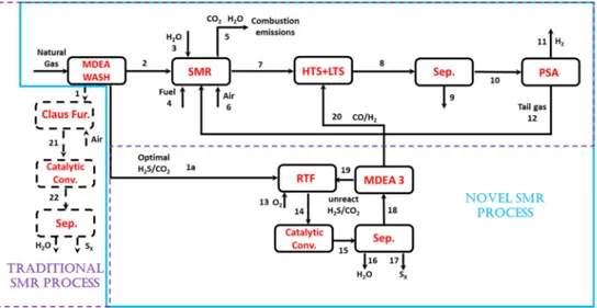
A typical SMR system consists of these main sequential units: desulfurizer, with the related Sulfur Recovery Unit (SRU), reformer, shift reactors and separation units (Figure 1). In Figure 2, a more detailed scheme of reforming furnace and shift reactor is reported.
Figure 1. Process diagram of conventional SMR process for hydrogen production
Figure 2. Typical flowsheet of steam methane process [6]
In the desulfurizer, sulfur is removed from natural gas to avoid the production of sulfur oxides (SOx) and the successive contamination of catalysts in the reformer [7]. As a consequence, desulfurizer produces sulfidic acid (H2S) as a by-product, that is usually converted into sulfur and water into the Claus process [8]. The latter is the most diffused, well-known and deeply studied process that allows to recover, at the same time, sulfur and thermal energy from acid gases [9]. Nowadays, many different configurations of this process are implemented (e.g SuperClaus or EuroClaus) [10] and a comparative analysis in commercial operation has been reported by Eow et al. [11]. In any case, the Claus process is commonly divided into two stages, thermal and catalytic as reported in Figure 3 and is based on the following global reaction:
Mitigating Carbon Dioxide Impact of Industrial ... Volume 8, Issue 1, pp 71-87
Figure 3. A schematic diagram of Claus process incorporating furnace (thermal) and catalytic stages [12]
In the reformer, a syngas containing hydrogen (H2) and carbon monoxide (CO) is produced by the reaction between hydrocarbons and steam. Then, there are two shift reactors that operate at different temperatures, both of which convert CO produced in the reformer into carbon dioxide (CO2) and H2 [13]. The initial High Temperature Shift (HTS) reactor takes advantage of the high reaction rates, but is thermodynamically limited, which results in a not complete conversion of carbon monoxide that is finalized in the following Low Temperature Shift (LTS) reactor. The main reactions involved in a SMR process are:
C H nH O nCO 2n 1 H (2)
CO H O H CO (3)
The net overall reaction is endothermic and the required heat could be supplied to the reformer in a different way. One possibility is to use an Autothermic Reforming reactor (ATR) with a standard one-step steam methane reforming [14]. It was reported that ATR at low Steam to Carbon (S/C) ratio should be the preferred technology for large scale plants since it maximizes the single line capacity and minimizes the investment [15]. However, it was also reported that the cost of the Air Separation Unit (ASU) offsets the savings made by using a cheaper reformer [16]. Thus in this work, it has been preferred to simulate the behavior of a standard SMR producing syngas with a high hydrogen excess and using the purge gas from the recycle loop as reforming furnace fuel [17]. Moreover, the excess of hydrogen in the reactor feed stream, gives a recycle stream with a higher Lower Heating Value (LHV). Some typical reformer operating conditions are listed as a temperature of 700-1,000 °C, a pressure of 15-50 bar and an S/C ratio between 2 and 5 [14]. The produced syngas is cooled before entering the shift reactor to remove the heat of the exothermic shift reaction [eq. (2)]. The gas stream exiting the shift reactors consists of H2, CO, CO2, H2O and the remaining methane (CH4). After separation and removal of the water using a condenser, the dry shifted stream enters or a downstream process (e.g. methanol production [18] and Fisher Tropsch synthesis [19]) or a hydrogen purification unit from which the final product H2 exits. There are two main technologies for hydrogen purification: Pressure Swing Adsorption (PSA) and membrane separation [20]. Due to the complicated nature of purification process, all separation and purification units are assumed in this study to be simple separation steps. After purification of H2 stream, the remaining tail gas leaves the PSA unit at near atmospheric pressure and with a high concentration of CO2. This tail gas is sent to furnace as a secondary feed stream in order to decrease the fuel consumption. The traditional process layout is summarized in Figure 1.
Mitigating Carbon Dioxide Impact of Industrial ... Volume 8, Issue 1, pp 71-87
As a consequence, SMR process plant emits about 7 kg of CO2 per 1 kg of H2 produced, which was equivalent to 220 Mt CO2 globally [21]. Carbon Capture and Storage (CCS) technology could be a way for decreasing these emissions [22]. However, carbon capture again consumes a lot of energy [23]. Basing on a recent idea [24], another attractive way to reduce the CO2 emissions is the conversion into valuable products (i.e. syngas) by means of reaction with H2S, that is another emission of this process as already mentioned. The global oxy-reduction reaction takes place in the Regenerative Thermal Reactor (RTR):
2H S +CO = H + CO + S + H O (4)
The Acid Gas to Syngas (AG2STM) technology exploits the hydrogen content of H2S as reducing agent for CO2 [25] and, at the same time, allows to use energy sources currently still unexploited because of their relevant sulfur content. Crude oils, natural gases, and different coals with high sulfur contents are promising candidates for this technology [26]. Moreover, AG2STM allows to substitute a mandatory process for the conversion of H2S (i.e. Claus process) that is not economically self-sustainable. In fact, the product with the highest economical value of the Claus process is not sulfur, but medium pressure steam produced in the Wasted Heat Boiler (WHB), that is energy recovery heat exchanger allows to recover heat coming from the effluent gaseous stream of Claus furnace. On the other hand, with AG2STM process, there is the production of both sulfur and medium pressure steam, but also the production of an additional amount of hydrogen that is an economically appealing product. It is important to underline the fact that this novel process was proved only at laboratory scale [27] and simulation level [28]. El-Melih et al. [27], showed that a suitable combination between H2S and CO2 at fixed temperature like 1,400 K allow to reach conversion of H2S and CO2 equal to 30% and 15% respectively. The target of this study is to evaluate the potential application of AG2STM technology on SMR. For this reason, a basic comparison between the old and the new process will be done both in terms of industrial feasibility, highlighting some critical parameters (e.g. furnace temperature or hydrogen sulfide conversion), and in terms of emissions reduction (i.e. LCA). Indeed, nowadays, processes are usually optimized in order to maximize industrial performance like productivity or to minimize economic values like payback time [29]. However, also the environmental impact is an important factor and it’s not easy to evaluate. The most complete approach to evaluate the environmental impact of a process or a product is the Life-Cycle Assessment or LCA analysis [30]. In this kind of study, the environmental impact is estimated considering all the stages of the process’s life, from the raw material extraction to the plant disposal [31]. Impacts of any material, fuel, process or emission are assessed. This analysis is very useful to compare two different processes or to identify in which stage one process is more polluting. Different kind of methods are available to assess the environmental impact, the most used and easy to understand are the carbon footprint and the water footprint [32], while others, like ReCiPe method [33], are complex to interpret but more complete. In this work, the carbon footprint of the process has been considered using as impact category the Global Warming Potential (GWP) according to International Panel in Climate Change (IPCC) [34].
PROCESS AND SIMULATION TOOLS
In this paragraph, the overall layout of the novel SMR process is discussed and then each part is analyzed with a description of models and tools. The commercial process simulation software Aspen HYSYS is used for this simulation excluding the regenerative thermal reactor and the furnace for AG2STM and Claus process respectively. Aspen HYSYS is a comprehensive process modeling system used by many oil and gas producers, refineries, and engineering companies around the world to optimize process
Mitigating Carbon Dioxide Impact of Industrial ... Volume 8, Issue 1, pp 71-87
design and operations [35]. Indeed, this software includes the material and heat balances of the most diffused unit operations like flashes, heat exchangers and distillation columns. The Peng-Robinson-Styjek-Vera (PRSV) equation of state is used for the entire process except for the amine wash section, where the amine package included in Aspen HYSYS is adopted [36]. PRSV assures a good description of non ideal systems by both enhancing pure compound vapor pressure prediction and employing proper mixing rules [15]. Figure 4 shows a simplified block flow diagram comparing the traditional SRU process with the novel one.
Figure 4. Block flow diagram of traditional and novel SMR processes
Amine wash units
The natural gas, as mentioned in the introduction paragraph, must be purified form acid gases (H2S and CO2). For this work, it is decided to use the methyl diethanolamine (MDEA) for its industrial application and its specific selectivity to hydrogen sulfide [37], which allows to control the ratio between H2S and CO2 that is crucial for AG2STM process. Moreover, the novel process presents an additional amine-washing unit, included in the AG2STM section. This sweetening aims to separate the extra syngas produced in the RTR from the unreacted acid gases that are recycled to the AG2STM process. The amine washing section is simulated entirely through HYSYS software, thanks to a template already existing in the commercial package. The configuration of an amine treatment unit is composed of a single absorption column, one regeneration column and all related equipment, such as pumps, heat exchangers and filters, as reported in Figure 5.
Mitigating Carbon Dioxide Impact of Industrial ... Volume 8, Issue 1, pp 71-87
Steam Methane Reforming Units (SMRU)
The model developed for this investigation is mainly based on the flow diagram provided by Soltani et al. [21]. The process is simulated using Aspen HYSYS that allows to analyse the case study under different operating conditions. Several assumptions are made by Soltani et al. [21] for the design and the analysis of the reforming process. Here are reported the most significant for this work:
• The hydrogen separation in the purifier (PSA) removes 90% of the hydrogen; • The product H2 stream is 100% pure with no other contaminants;
• The furnace is a Gibbs reactor (the presence of CO, H2, CO2 makes a stoichiometric reactor model complicated and inadequately accurate);
• The reformer reactor and the two shift reactors are equilibrium reactor that includes the reactions eq. (2) and eq. (3).
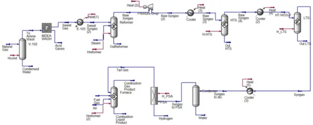
The thermodynamic integrity of the simplified model is assured by setting appropriate reactor temperatures and flow stream temperatures. The developed Aspen HYSYS flowsheet is shown in Figure 6 and the pressures, temperatures and pressure drops are presented in Table 1. For further information see the work of Soltani et al. [21].
Figure 6. Schematic Aspen HYSYS model of SMR
Table 1. Operating parameters considered for modeling SMR process [12]
Flow stream Temperature [°C] Pressure [bar]
Steam feed 200.0 30.0
Natural gas feed 38.0 30.0
Reformed gas 815.0 19.5
Cooled gas to HTS 350.0 19.0
Cooled gas to LTS 204.0 18.0
Shifted gas to purification 213.0 17.0
Dry syngas 38.0 16.6
Pure H2 38.0 1.60
PSA tail gas 38.0 1.00
Furnace fuel 25.0 1.00
Air inlet to furnace 25.0 1.00
Device Outlet temperature [°C] Pressure drop [bar]
Reformer 815 1.72
HTS 428.0 1.03
LTS 213.0 1.03
Mitigating Carbon Dioxide Impact of Industrial ... Volume 8, Issue 1, pp 71-87
Claus process (Traditional Steam Methane Reforming process)
As already mentioned in the introduction, Claus process can be divided into two main sections: thermal and catalytic. The latter is simulated using conversion reactor in Aspen HYSYS. The main reactions involved in the catalytic section are the reduction of H2S reacting with sulfur dioxide (SO2) [i.e. Claus reaction, eq. (5)] and the hydrolysis of carbonyl sulfide (COS) [eq. (6)] and carbon disulfide (CS2) [eq. (7)]:
2H S + SO =
3
xS + 2H O (5)
COS + H O = H S + CO (6)
CS + 2H O = 2H S + CO (7)
The typical conversion of the hydrolysis reaction is about 75% on alumina catalyst and of about 97% for Claus reaction [38]. On the other hand, the thermal section was simulated using a detailed kinetic scheme using DSMOKE software [9]. The detailed kinetic scheme selected is made up of three different subsets of reactions that describe the kinetics of carbon [39], sulfur [40] and nitrogen [41]. DSMOKE has a simple interface for reactors network construction and there is also a sensitivity analysis tool that can be very useful to investigate which reactions have an important contribution to the simulation results. This computational tool uses standard material and energy balances of Continuous Stirred-Tank Reactor (CSTR) and Plug Flow Reactor (PFR) reactors and in particular:
• PFR reactor material and energy balance:
= = 1, … , NC ! "#$ (8) %& '= (−Δ+ , +-. /1 ('0 . /− ') ! "#$ (9)
• CSTR reactor material and energy balance:
− 2 = ! "#$ = 1, … , NC (10) (−Δ+ , =1 ! 2(+3 − +456) #$ +6-8 ('. / . /− ') ! "#$ (11)
This code is integrated within Aspen HYSYS with the use of MATLAB. This allows to include a detailed kinetic scheme, within non-ideal reactor models and in turn into commercial environments for the simulation of chemical plants. According to the work of Manenti et al. [9], the Claus furnace and waste heat boiler can be simulated by means of several kinds of reactors in series (see Figure 7). This simplified configuration (computational fluid-dynamics is not considered) is also useful for on-line purposes since it allows to perform simulations with small computational effort. According to the fast ignition of H2S with respect to the other species, an equilibrium reactor is adopted to
Mitigating Carbon Dioxide Impact of Industrial ... Volume 8, Issue 1, pp 71-87
simulate the first portion of the thermal reactor furnace. Next, two plug-flow reactors are adopted to simulate the remaining portion of the thermal reaction furnace and the waste heat boiler.
Figure 7. Claus thermal furnace: simulation with ideal reactor series
Acid Gas to Syngas technology (Novel Steam Methane Reforming process)
The core of the novel SMR process is the RTR, which has a different configuration compared with the typical Claus furnace [10] (see Figure 8). RTR allows to reach the aim of this process that is to recover as much as possible hydrogen from the H2S. The key idea is to feed an optimal ratio of H2S and CO2 and to preheat the inlet acid gas before the combustion. In this way, H2S pyrolysis produces hydrogen selectively H2. Therefore, it is convenient to feed the acid gases to the RTR at high temperatures (e.g. 700 °C) in order to reduce the oxygen flow rate required to reach the furnace temperatures (1,100-1,350 °C). In this way, the oxygen stream is much lower than the typical oxygen provided to the Claus processes and the H2S potential for pyrolysis is completely exploited. As in the traditional Claus process, the released heat is recovered generating medium-pressure steam in a WHB. The latter and recycle pre-heating equipment could be considered a portion of the RTR, because they play a key role in the regenerative process. Actually, the RTR is similar to the Claus thermal furnace, but redesigned from the constructive point of view (Figure 8). For these reasons, the RTR could be simulated as:
• Furnace (a): Adiabatic plug flow reactor using DSMOKE with detailed kinetic; • WHB (b): Non-isothermal plug flow reactor using DSMOKE with detailed kinetic; • Economizer (c): Heat exchanger in Aspen HYSYS.
Figure 8. RTR configuration: furnace (a); WHB (b) and economizer (c)
The catalytic reactor configuration is the typical one of the Claus process, and so it is simulated using a conversion reactor in Aspen HYSYS (see the previous paragraph).
Mitigating Carbon Dioxide Impact of Industrial ... Volume 8, Issue 1, pp 71-87
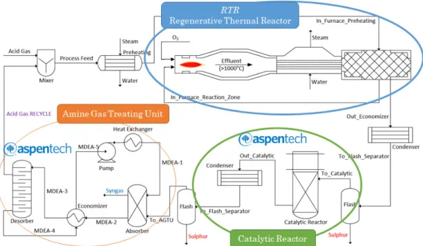
Figure 9 reports the process flow diagram of the AG2STM technology and summarizes the simulation tools used for each unit. It is important to notice that this configuration take advantage by unreacted acid gases recycle.
Figure 9. Process flow diagram of AG2STM technology
RESULTS AND DISCUSSION
The evaluation of the potentiality of the AG2STM technology application on SMR process is related to the natural gas feedstock and in particular to the quantity of H2S present. In general, the H2S composition in an industrial SMR changes from 0% to about 6% [42]. In this work, in order to prove the validity of the novel process, a natural gas with 5.38% mol of H2S was chosen [37]. Indeed, this novel process exploits its potentiality with high H2S content which leads to a higher syngas recovery and allows the use of raw material with high sulfur content that nowadays are unused. In any case, this process could work also for less content of H2S. The feed composition is reported in Table 2.
Table 2. Natural gas compositions and quantities [37]
Component Mole [%]
Hydrogen sulfide (H2S) 5.38
Carbon dioxide (CO2) 4.48
Nitrogen (N2) 0.11 Methane (CH4) 63.35 Ethane (C2H6) 13.90 Propane (C3H8) 6.03 Iso-Butane (i-C4H10) 1.36 Normal-Butane (n-C4H10) 2.44 Iso-Pentane (i-C5H12) 1.03 Normal-Pentane (n-C5H12) 0.73 Hexane (C6H14) 1.19 Water (H2O) 0.00 Total 100.00
Mitigating Carbon Dioxide Impact of Industrial ... Volume 8, Issue 1, pp 71-87
According to the stream numbers of Figure 4, the simulation results both of the traditional SMR process and of the novel one using the AG2STM technology are reported in the next paragraphs. In both simulation cases, S/C for the steam reforming reactor is equal to 3. Moreover, the additional fuel gas that entering the reformer is mainly composed by methane (80% mol), CO2 (7% mol) and light hydrocarbons (13% mol).
Traditional Steam Methane Reforming process
Table 3 and Table 4 reports the results of Aspen HYSYS simulation of the traditional SMR process. The simulation results completely agree with the ones prosed by Soltani
et al. [21]. Indeed, the kg of CO2 emitted per kg of H2 produced is equal to 7.25 instead of
the 6.3 obtained by Soltani without considering the combustion furnace emissions. Again, the same ratio is equal to 14.37 instead of the 12.3 proposed by Soltani with considering the combustion furnace emissions. Finally, the additional fuel consumption is equal to 62.36 ton/h and the sulfur produced is 8.80 ton/h with a sulfur recovery yield equal to 94.80%.
Table 3. Simulation results traditional SMR process: stream compositions (mol fractions)
Traditional SMR process
Stream n° [kg/h] CO CO2 H2 CH4 H2S H2O CnH(2n+1) N2 Natural gas 1.369E5 Composition in Table 2
1 1.442E4 0.00 0.19 0.00 0.00 0.71 0.05 0.04 0.00 2 1.229E5 0.00 0.03 0.00 0.68 0.00 0.00 0.29 0.00 5 2.085E6 0.00 0.15 0.00 0.00 0.00 0.17 0.00 0.68 7 5.289E5 0.08 0.07 0.42 0.06 0.00 0.37 0.00 0.00 8 5.289E5 0.00 0.14 0.49 0.06 0.00 0.31 0.00 0.00 11 3.421E4 0.00 0.00 1.00 0.00 0.00 0.00 0.00 0.00 12 2.839E4 0.00 0.58 0.19 0.22 0.00 0.01 0.00 0.00
Table 4. Simulation results traditional SMR process (Claus section): stream compositions (mol fractions)
Traditional SMR process (Claus section)
Stream n° [kg/h] CO CO2 H2 H2S SO2 COS CS2 S2 N2 H2O 21 4.302E4 0.02 0.07 0.01 0.04 0.02 0.01 0.00 0.07 0.55 0.22 22 4.088E4 0.02 0.08 0.01 0.00 0.00 0.00 0.00 0.08 0.56 0.25
Novel Steam Methane Reforming production
As already mentioned, the novel SMR process is designed using as target the same hydrogen production of the traditional process. Table 5 and Table 6 show the results of the simulation of the novel SMR process.
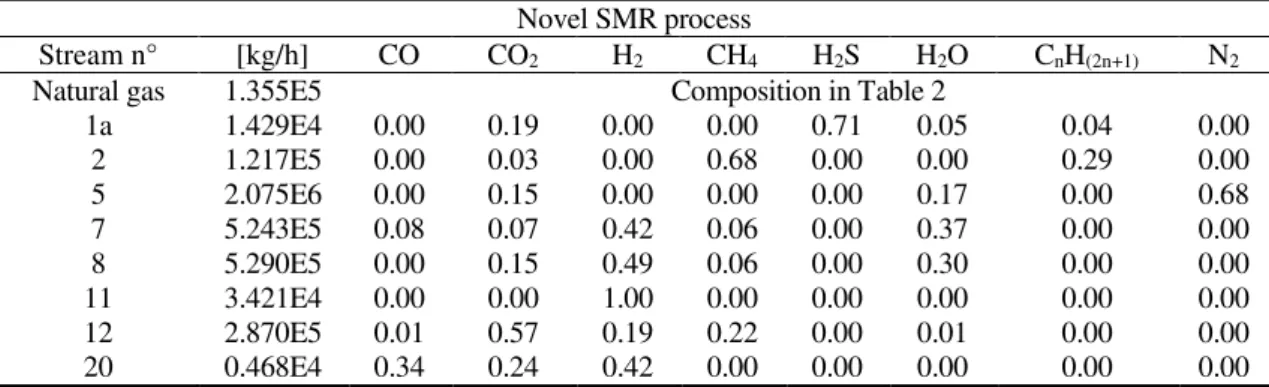
Table 5. Simulation results novel SMR process: stream compositions (mol fractions)
Novel SMR process
Stream n° [kg/h] CO CO2 H2 CH4 H2S H2O CnH(2n+1) N2 Natural gas 1.355E5 Composition in Table 2
1a 1.429E4 0.00 0.19 0.00 0.00 0.71 0.05 0.04 0.00 2 1.217E5 0.00 0.03 0.00 0.68 0.00 0.00 0.29 0.00 5 2.075E6 0.00 0.15 0.00 0.00 0.00 0.17 0.00 0.68 7 5.243E5 0.08 0.07 0.42 0.06 0.00 0.37 0.00 0.00 8 5.290E5 0.00 0.15 0.49 0.06 0.00 0.30 0.00 0.00 11 3.421E4 0.00 0.00 1.00 0.00 0.00 0.00 0.00 0.00 12 2.870E5 0.01 0.57 0.19 0.22 0.00 0.01 0.00 0.00 20 0.468E4 0.34 0.24 0.42 0.00 0.00 0.00 0.00 0.00
Mitigating Carbon Dioxide Impact of Industrial ... Volume 8, Issue 1, pp 71-87
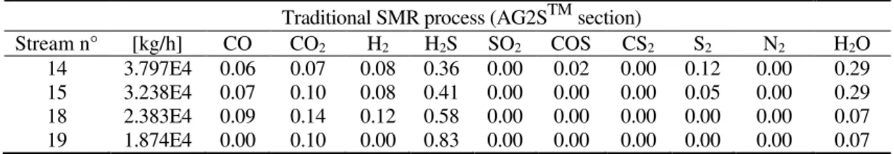
Table 6. Simulation results novel SMR process (AG2STM section): stream compositions
(mol fractions)
Traditional SMR process (AG2STM section)
Stream n° [kg/h] CO CO2 H2 H2S SO2 COS CS2 S2 N2 H2O 14 3.797E4 0.06 0.07 0.08 0.36 0.00 0.02 0.00 0.12 0.00 0.29 15 3.238E4 0.07 0.10 0.08 0.41 0.00 0.00 0.00 0.05 0.00 0.29 18 2.383E4 0.09 0.14 0.12 0.58 0.00 0.00 0.00 0.00 0.00 0.07 19 1.874E4 0.00 0.10 0.00 0.83 0.00 0.00 0.00 0.00 0.00 0.07
The first thing to notice in these results is the fact that the mass flow rate of the natural gas is less than in the traditional case of about 1.06%. This leads anyway to the same hydrogen production. This is due to the AG2S™ technology that allows not only to convert a certain amount of CO2 but also to produce an additional amount of syngas (see stream n° 20). The regenerative thermal furnace works at atmospheric pressure with an inlet oxygen mass flow rate equal to 4,550 kg/h. The temperature reached in the furnace is equal to 1,250 °C. WHB is designed to quench the thermal reactor effluent so as to prevent any possible recombination effect, which has been proven to be significant during relatively slow cooling [43]. Moreover, the extra syngas leads to an additional amount of tail gases that directly reduce the necessary quantity of fuel gas. Indeed, the total amount of fuel gas that is used in this case is reduced of about 0.63%. As a consequence, the overall CO2 emissions are reduced to about 0.84% and in particular of 4.13 ton/h of CO2. The outlet H2S and SO2 are equal to zero. The complete conversion of H2S is reached, as in the traditional Claus process, with an extra production of syngas.
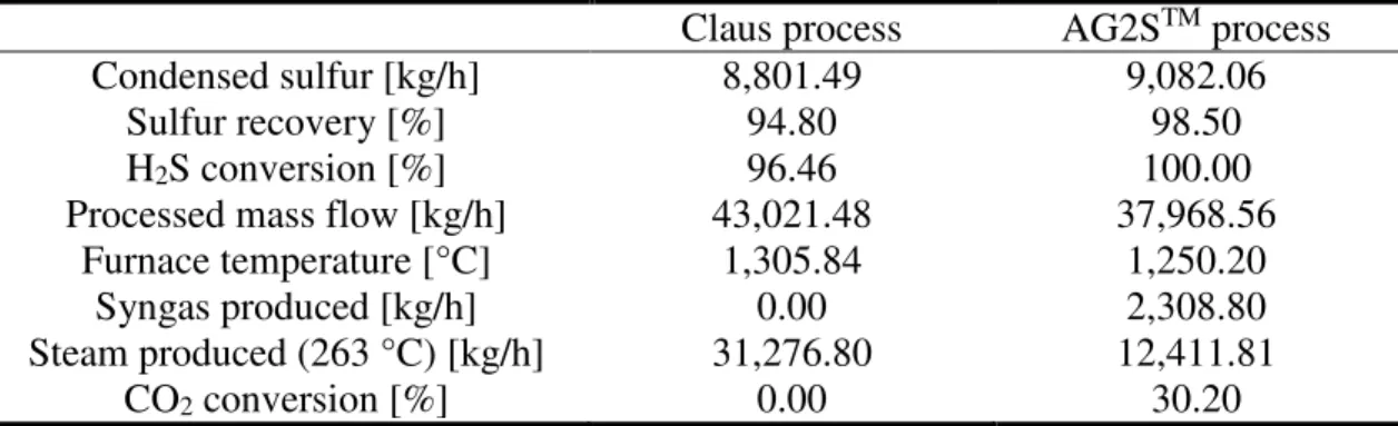
Technical feasibility revamping of Acid Gas to Syngas process
The target of this section is to propose and demonstrate the sustainability and the industrial revamp feasibility of AG2STM technology. A comparison between Claus and AG2STM process is shown, choosing some critical parameters (e.g. furnace temperature or hydrogen sulfide conversion). The importance of introduced innovations is highlighted, both at technical and environmental level and the obtained results are analyzed through a comparison from a technical point of view of the standard Claus process and the AG2STM revamped one. At first sight, looking at Table 7, it is evident that both sulfur recovery efficiency, defined as the percentage of the sulfur in the feed that is condensed, and H2S conversion is higher in the case of the revamped process. This is due to the fact that the unreacted H2S is almost all recycled to the AG2STM process. Usually, chemical plants with one or more recycles, whose purpose is to increase products’ yield, work with higher mass flow rates. Therefore, it is expected to observe a significant difference in Table 7 but processed mass flow rates are similar for both processes. Indeed, the standard Claus plant, a once-through process, works with a huge amount of nitrogen, introduced in the furnace with the air flow instead of the AG2STM process that works with oxygen stream, but manipulates a higher acid gas flow rate with respect to the standard plant, due to the recycling. One of the disadvantages of the novel solution is the introduction, in the furnace, of pure oxygen that makes an air separation plant upstream necessary. However, this cost item is very well balanced with the need, for a standard system, to increase the equipment volumes in order to treat the same acid gas amount of the revamped process. Therefore, the real and most important innovations of the revamped Claus process with respect to the old one, from a technological point of view, are the production of syngas and the reuse of a polluting emission, i.e. CO2, to produce valuable products. This synthetic gas can be sold, bringing an immediate economic advantage or can be added to the syngas stream generated, for example, by an upstream gasification plant (to increase the amount of syngas produced starting from the same coal
Mitigating Carbon Dioxide Impact of Industrial ... Volume 8, Issue 1, pp 71-87
feed). Moreover, syngas can be also used in a downstream section of the plant, assigned to the production of methanol or to Fischer Tropsch Synthesis (FTS).
Table 7. Comparisons between Claus and AG2STM process in terms of some key parameters
Claus process AG2STM process
Condensed sulfur [kg/h] 8,801.49 9,082.06
Sulfur recovery [%] 94.80 98.50
H2S conversion [%] 96.46 100.00
Processed mass flow [kg/h] 43,021.48 37,968.56
Furnace temperature [°C] 1,305.84 1,250.20
Syngas produced [kg/h] 0.00 2,308.80
Steam produced (263 °C) [kg/h] 31,276.80 12,411.81
CO2 conversion [%] 0.00 30.20
Finally, it is important to underline the fact that AG2STM process is similar to the Claus process in terms of unit operations involved. Indeed, AG2STM presents a furnace, a WHB and a catalytic reactor and also the amine wash could be related to mandatory tail gas treatment unit for the Claus process [44]. The only novel unit is the gas-gas heat exchanger that is used for heat recovery with the consequent acid gas pre-heating. Moreover, as already mentioned, AG2STM process treats about the same amount of acid gases flow rate compared to the Claus process. So, from the point of view of energy consumption, the novel process seems to have the same energy usage of the old one. The only section with higher energy consumption, which needs further study, is the washing section because the mass flow rate of acid gas recycle is higher compared to the stream related to the tail gas treatment unit of the Claus process. For these reasons, AG2STM process seems to be economically attractive due to the extra hydrogen production opposed to the investment cost of the novel heat exchanger and the operative cost of the amine wash unit.
Environmental impact comparison (Life-Cycle Assessment)
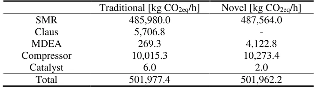
Finally, in this work, a first basic environmental impact evaluation was performed. The AG2STM technology, as already mentioned, was design to use the same units of Claus process. In this way two different achievements can be reached, minimizing the revamping costs and avoid energy and material consumption to produce the new plant and dispose the old one. The RTR has the same dimensions and materials of the traditional Claus furnace and WHB. There are only two differences between AG2STM and Claus process. The first uses one catalytic reactor instead of three but it requires a new ammine treatment unit to separate the produced syngas (hydrogen and carbon monoxide) from unreacted acid gases (see Figure 6). The rest of the plant is the same and for this reason the impact of the two plants is considered equivalent. The carbon footprint of the two processes was evaluated considering the carbon emissions, the heat demand and the electrical energy use. In particular, the emissions due to SMR furnace, MDEA regenerator, compressors and catalyst use were evaluated. According to IPCC GWP 100 years 2013, the carbon footprint considered for electrical energy, heat production and catalyst production are, respectively, 433 g CO2eq/kWhe, 204 g CO2eq/kWht and 1.47 g CO2eq/gcatalyst [45]. As reported in Table 8, the total carbon emissions are 501,977.4 kg/h for traditional process and 501,962.2 kg/h with AG2STM technology. Differently from what mentioned before, CO2 emissions are the same.
Considering not only the CO2 produced during the main process, but also the emissions due to the utilities, the appealing of the new technology seems to decrease. This is due to the presence of a second amine treatment unit, which requires a larger
Mitigating Carbon Dioxide Impact of Industrial ... Volume 8, Issue 1, pp 71-87
quantity of heat that balance the CO2 consumed in the AG2S™ stage. However, this drawback could be overlooked if the regeneration heat is provided by steam that could be generated directly in the process itself. In this case, the CO2 emissions could be reduced up to 0.77%. The carbon footprint of both processes is mainly due to emissions of steam reforming furnace and only in minor part (about 4%) by other process stages like MDEA, compressors and catalyst. Environmental impact could be further reduced changing the use of syngas. If the latter will be used to produce chemicals, the carbon footprint of the new process could decrease by about 3%. A more detailed LCA analysis could be useful to optimize the AG2STM process not only by an economic point of view but also by an environmental one.
Table 8. Carbon footprint comparison between traditional and new technology Traditional [kg CO2eq/h] Novel [kg CO2eq/h]
SMR 485,980.0 487,564.0 Claus 5,706.8 - MDEA 269.3 4,122.8 Compressor 10,015.3 10,273.4 Catalyst 6.0 2.0 Total 501,977.4 501,962.2 CONCLUSION
The paper presented a novel effective and environmentally friendly solution for industrial steam reforming process that allows to decrease the consumption of the natural gas sources reaching the same production of hydrogen. The basic idea is to apply a novel technology, AG2STM, that allows to reduce the emissions of H2S and CO2 and, at the same time, to exploit the oxidizing capacity of CO2 with H2S to ease the recovery of syngas. Coupling two different software, i.e. Aspen HYSYS and MATLAB, in order to include a detailed kinetic scheme, the traditional and the novel steam reforming process were simulated and compared in terms of some key parameters. The most important results are the decrease of CO2 emissions (about 0.84%), primary feedstock (about 1.06%) and additional fuel to the steam reforming reactor (about 0.63%). Furthermore, is demonstrated that a natural gas charge with a high sulfur content mean a higher reduction of CO2 emissions. It is worth considering that the application of such a technology is not yet optimized in terms of feedstock and operating conditions. For these reasons, given the innovative nature of the process, this technology requires more detailed analysis (e.g. unit dimension and design, energy consumption, optimized operating conditions), before it could be used on a real industrial plant, but this highlight that the novel process is very interesting and economically appealing. Finally, a first study of the environmental impact of the processes was done. Carbon emissions depend mainly by SMR furnace. AG2STM technology, coupled with SMR process, could be used to reduce the CO2 emissions up to 0.77%. The value could be increased to about 3% if the syngas produced is converted to chemicals instead of hydrogen through Water Gas Shift (WGS) process. For sure, LCA analysis should be improved considering also equipment.
NOMENCLATURE
cp mixture specific heat at constant pressure [kcal/kgK]
D reactor diameter [m]
Hi mass enthalpy of the i species [kcal/kg] (ADD)
Rj reaction rate of the j reaction [kmol/m3s]
Mitigating Carbon Dioxide Impact of Industrial ... Volume 8, Issue 1, pp 71-87
T temperature of the system [K]
Text external reactor temperature [K]
Uext overall heat exchange coefficient [kW/m2/K]
V reactor volume [m3]
Wi molecular weight of i species [kg/kmol]
Greek letters
τ contact time [s]
υij stoichiometric coefficient of i species in the j reaction [-]
ωi mass fraction of i species [-]
2
mass fraction of i species at initial condition [-]
ΔHj heat generated from the j reaction [kcal/kg]
Abbreviations
AG2S Acid Gas To Syngas
ASU Air Separation Unit
ATR Auto-Thermal Reforming Reactor
GWP Global Warming Potential
HTS High Temperature Shift Reactor
IPCC International Panel in Climate Change
LCA Life Cycle Assessment
LHV Lower Heating Value
LTS Low Temperature Shift Reactor
MDEA Metal Di-Ethanol Amine
NC Number of Components
NR Number of Reactions
PRSV Peng-Robinson-Styjek-Vera
PSA Pressure Swing Adsorption
RTR Regenerative Thermal Reactor
SMR Steam Methane Reforming
SRU Sulfur Recovery Unit
WGS Water Gas Shift
WHB Waste Heat Boiler
REFERENCES
1. Wang, T. and Lin, B., Chinaʼs Natural Gas Consumption and Subsidies—From a
Sector Perspective, Energy Policy, Vol. 65, pp 541-551, 2014,
https://doi.org/10.1016/j.enpol.2013.10.065
2. Bassani, A., Bozzano, G., Pirola, C., Frau, C., Pettinau, A., Maggio, E., Ranzi, E. and Manenti, F., Sulfur Rich Coal Gasification and Low Impact Methanol Production,
Journal of Sustainable Development of Energy, Water and Environment Systems,
Vol. 6, No. 1, pp 210-226, 2018, https://doi.org/10.13044/j.sdewes.d5.0188
3. Howarth, R. W., Santoro, R. and Ingraffea, A., Methane and the Greenhouse-gas Footprint of Natural Gas from Shale Formations, Climatic Change, Vol. 106, No. 4, pp 679, 2011, https://doi.org/10.1007/s10584-011-0061-5
4. Xu, J., Yeung, C. M., Ni, J., Meunier, F., Acerbi, N., Fowles, M. and Tsang, S. C., Methane Steam Reforming for Hydrogen Production using Low Water-ratios Without Carbon Formation Over Ceria Coated Ni Catalysts, Applied Catalysis A:
General, Vol. 345, No. 2, pp 119-127, 2008,
https://doi.org/10.1016/j.apcata.2008.02.044
5. Dufour, J., Serrano, D., Galvez, J., Moreno, J. and Garcia, C., Life Cycle Assessment of Processes for Hydrogen Production. Environmental Feasibility and Reduction of
Mitigating Carbon Dioxide Impact of Industrial ... Volume 8, Issue 1, pp 71-87
Greenhouse Gases Emissions, International Journal of Hydrogen Energy, Vol. 34, No. 3, pp 1370-1376, 2009, https://doi.org/10.1016/j.ijhydene.2008.11.053
6. Kumar, A., Baldea, M. and Edgar, T. F., A Physics-based Model for Industrial Steam-methane Reformer Optimization with Non-uniform Temperature Field,
Computers & Chemical Engineering, Vol. 105, pp 224-236, 2017,
https://doi.org/10.1016/j.compchemeng.2017.01.002
7. Israelson, G., Results of Testing Various Natural Gas Desulfurization Adsorbents,
Journal of Materials Engineering and Performance, Vol. 13, No. 3, pp 282-286,
2004, https://doi.org/10.1361/10599490419199
8. Manenti, F., Papasidero, D., Bozzano, G., Pierucci, S., Ranzi, E. and Buzzi-Ferraris, G., Total Plant Integrated Optimization of Sulfur Recovery and Steam Generation for Claus Processes Using Detailed Kinetic Schemes, Computer Aided Chemical
Engineering, pp 811-816, 2013, https://doi.org/10.1016/B978-0-444-63234-0.50136-6
9. Manenti, F., Papasidero, D., Frassoldati, A., Bozzano, G., Pierucci, S. and Ranzi, E., Multi-Scale Modeling of Claus Thermal Furnace and Waste Heat Boiler Using Detailed Kinetics, Computers & Chemical Engineering, Vol. 59, pp 219-225, 2013, https://doi.org/10.1016/j.compchemeng.2013.05.028
10. Gupta, A., Ibrahim, S. and Al Shoaibi, A., Advances in Sulfur Chemistry for Treatment of Acid Gases, Progress in Energy and Combustion Science, Vol. 54, pp 65-92, 2016, https://doi.org/10.1016/j.pecs.2015.11.001
11. Eow, J. S., Recovery of Sulfur from Sour Acid Gas: A Review of the Technology,
Environmental Progress & Sustainable Energy, Vol. 21, No. 3, pp 143-162, 2002,
https://doi.org/10.1002/ep.670210312
12. Ibrahim, S., Al Shoaibi, A. and Gupta, A., Role of Btx on Sulfur Recovery Chemistry in Thermal Stage Claus Reactors, Conference Paper, Brimstone Middle East Sulfur Symposium, Abu Dhabi, UAE, 2015.
13. Xu, J. and Froment, G. F., Methane Steam Reforming, Methanation and Water ‒ Gas Shift: I. Intrinsic Kinetics, Aiche Journal, Vol. 35, No. 1, pp 88-96, 1989, https://doi.org/10.1002/aic.690350109
14. Dybkjær, I., Tubular Reforming and Autothermal Reforming of Natural Gas—An Overview of Available Processes, Fuel Processing Technology, Vol. 42, No. 2-3, pp 85-107, 1995, https://doi.org/10.1016/0378-3820(94)00099-F
15. Pellegrini, L. A., Soave, G., Gamba, S. and Langè, S., Economic Analysis of a Combined Energy-Methanol Production Plant, Applied Energy, Vol. 88, No. 12, pp 4891-4897, 2011, https://doi.org/10.1016/j.apenergy.2011.06.028
16. Lange, J.-P., Methanol Synthesis: A Short Review of Technology Improvements,
Catalysis Today, Vol. 64, No. 1-2, pp 3-8, 2001,
https://doi.org/10.1016/S0920-5861(00)00503-4
17. Bhat, S. A. and Sadhukhan, J., Process Intensification Aspects for Steam Methane Reforming: An Overview, Aiche Journal, Vol. 55, No. 2, pp 408-422, 2009, https://doi.org/10.1002/aic.11687
18. Bozzano, G. and Manenti, F., Efficient Methanol Synthesis: Perspectives, Technologies and Optimization Strategies, Progress in Energy and Combustion
Science, Vol. 56, pp 71-105, 2016, https://doi.org/10.1016/j.pecs.2016.06.001
19. Comazzi, A., Pirola, C., Longhi, M., Bianchi, C. L. and Suslick, K. S., Fe-Based Heterogeneous Catalysts for the Fischer-Tropsch Reaction: Sonochemical Synthesis and Bench-Scale Experimental Tests, Ultrasonics Sonochemistry, Vol. 34, pp 774-780, 2017, https://doi.org/10.1016/j.ultsonch.2016.07.012
20. Simpson, A. P. and Lutz, A. E., Exergy Analysis of Hydrogen Production via Steam Methane Reforming, International Journal of Hydrogen Energy, Vol. 32, No. 18, pp 4811-4820, 2007, https://doi.org/10.1016/j.ijhydene.2007.08.025
21. Soltani, R., Rosen, M. and Dincer, I., Assessment of CO2 Capture Options from Various Points in Steam Methane Reforming For Hydrogen Production, International
Mitigating Carbon Dioxide Impact of Industrial ... Volume 8, Issue 1, pp 71-87
Journal of Hydrogen Energy, Vol. 39, No. 35, pp 20266-20275, 2014,
https://doi.org/10.1016/j.ijhydene.2014.09.161
22. Li, B., Duan, Y., Luebke, D. and Morreale, B., Advances in CO2 Capture Technology: A Patent Review, Applied Energy, Vol. 102, pp 1439-1447, 2013, https://doi.org/10.1016/j.apenergy.2012.09.009
23. Pettinau, A., Ferrara, F. and Amorino, C., Combustion vs. Gasification for a
Demonstration ccs (Carbon Capture and Storage) Project in Italy:
A Techno-Economic Analysis, Energy, Vol. 50, pp 160-169, 2013, https://doi.org/10.1016/j.energy.2012.12.012
24. Bassani, A., Pirola, C., Maggio, E., Pettinau, A., Frau, C., Bozzano, G., Pierucci, S., Ranzi, E. and Manenti, F., Acid Gas to Syngas (AG2S™) Technology Applied to Solid Fuel Gasification: Cutting H2S and CO2 Emissions by Improving Syngas
Production, Applied Energy, Vol. 184, pp 1284-1291, 2016,
https://doi.org/10.1016/j.apenergy.2016.06.040
25. Manenti, F., CO2 as Feedstock: A New Pathway to Syngas, Computer Aided
Chemical Engineering, Vol. 37, pp 1049-1054, 2015,
https://doi.org/10.1016/B978-0-444-63577-8.50020-6
26. Frau, C., Ferrara, F., Orsini, A. and Pettinau, A., Characterization of Several Kinds of Coal and Biomass for Pyrolysis and Gasification, Fuel, Vol. 152, pp 138-145, 2015, https://doi.org/10.1016/j.fuel.2014.09.054
27. El-Melih, A., Ibrahim, S., Gupta, A. and Al Shoaibi, A., Experimental Examination of Syngas Recovery from Acid Gases, Applied Energy, Vol. 164, pp 64-68, 2016, https://doi.org/10.1016/j.apenergy.2015.11.025
28. Bassani, A., Manenti, F., Ranzi, E., Lima, N. and Zuniga Linan, L., Novel Coal Gasification Process: Improvement of Syngas Yield and Reduction of Emissions,
Chemical Engineering Transactions, Vol. 43, pp 1483-1488, 2015,
https://doi.org/10.3303/CET1543248
29. Manenti, F., Papasidero, D., Bozzano, G. and Ranzi, E., Model-Based Optimization of Sulfur Recovery Units, Computers & Chemical Engineering, Vol. 66, pp 244-251, 2014, https://doi.org/10.1016/j.compchemeng.2014.01.019
30. Galli, F., Pirola, C., Previtali, D., Manenti, F. and Bianchi, C. L., Eco Design LCA of an Innovative Lab Scale Plant for the Production of Oxygen-Enriched Air. Comparison Between Economic and Environmental Assessment, Journal of Cleaner
Production, Vol. 171, pp 147-152, 2018, https://doi.org/10.1016/j.jclepro.2017.09.268
31. Wolf, M.-A., Chomkhamsri, K., Brandao, M., Pant, R., Ardente, F., Pennington, D. W., Manfredi, S., De Camillis, C. and Goralczyk, M., ILCD Handbook, General Guide for Life Cycle Assessment ‒ Detailed Guidance, 2010.
32. Galli, A., Wiedmann, T., Ercin, E., Knoblauch, D., Ewing, B. and Giljum, S., Integrating Ecological, Carbon and Water Footprint Into a “Footprint Family” of Indicators: Definition and Role in Tracking Human Pressure on the Planet,
Ecological Indicators, Vol. 16, pp 100-112, 2012,
https://doi.org/10.1016/j.ecolind.2011.06.017
33. Goedkoop, M., Heijungs, R., Huijbregts, M., De Schryver, A., Struijs, J. and Van Zelm, R., Recipe 2008: A Life Cycle Impact Assessment Method Which Comprises Harmonised Category Indicators at the Midpoint and the Endpoint Level, 2009. 34. Bhandari, M., The Role of International Organization in Addressing the Climate
Change Issues and Creation of Intergovernmental Panel on Climate Change (IPCC),
Adv. Agr. Environ. Sci., Vol. 1, No. 1, pp 00005, 2018,
https://doi.org/10.30881/aaeoa.00005
35. Lam, H. L., Klemeš, J. J., Kravanja, Z. and Varbanov, P. S., Software Tools Overview: Process Integration, Modelling and Optimisation for Energy Saving and Pollution Reduction, Asia ‒ Pacific Journal of Chemical Engineering, Vol. 6, No. 5, pp 696-712, 2011, https://doi.org/10.1002/apj.469
Mitigating Carbon Dioxide Impact of Industrial ... Volume 8, Issue 1, pp 71-87
36. Al-Lagtah, N. M., Al-Habsi, S. and Onaizi, S. A., Optimization and Performance Improvement of Lekhwair Natural Gas Sweetening Plant Using Aspen HYSYS,
Journal of Natural Gas Science and Engineering, Vol. 26, pp 367-381, 2015,
https://doi.org/10.1016/j.jngse.2015.06.030
37. Abdulrahman, R. and Sebastine, I., Natural Gas Sweetening Process Simulation and Optimization: A Case Study of Khurmala Field in Iraqi Kurdistan Region, Journal of
Natural Gas Science and Engineering, Vol. 14, pp 116-120, 2013,
https://doi.org/10.1016/j.jngse.2013.06.005
38. Rhodes, C., Riddel, S. A., West, J., Williams, B. P. and Hutchings, G. J., The Low-Temperature Hydrolysis of Carbonyl Sulfide and Carbon Disulfide: A Review, Catalysis Today, Vol. 59, No. 3-4, pp 443-464, 2000, https://doi.org/10.1016/S0920-5861(00)00309-6
39. Ranzi, E., Frassoldati, A., Grana, R., Cuoci, A., Faravelli, T., Kelley, A. and Law, C., Hierarchical and Comparative Kinetic Modeling of Laminar Flame Speeds of Hydrocarbon and Oxygenated Fuels, Progress in Energy and Combustion Science, Vol. 38, No. 4, pp 468-501, 2012, https://doi.org/10.1016/j.pecs.2012.03.004
40. Manenti, F., Papasidero, D. and Ranzi, E., Revised Kinetic Scheme for Thermal Furnace of Sulfur Recovery Units, Chemical Engineering Transactions, Vol. 32, pp 1285-1290, 2013, https://doi.org/10.3303/ACOS1311023
41. Frassoldati, A., Faravelli, T. and Ranzi, E., Kinetic Modeling of the Interactions Between NO and Hydrocarbons at High Temperature, Combustion and Flame, Vol. 135, No. 1-2, pp 97-112, 2003, https://doi.org/10.1016/S0010-2180(03)00152-4 42. Kopyscinski, J., Schildhauer, T. J. and Biollaz, S. M., Production of Synthetic Natural
Gas (SNG) from Coal and Dry Biomass – A Technology Review from 1950 to 2009,
Fuel, Vol. 89, No. 8, pp 1763-1783, 2010, https://doi.org/10.1016/j.fuel.2010.01.027 43. Manenti, G., Papasidero, D., Manenti, F., Bozzano, G. and Pierucci, S., Design of
SRU Thermal Reactor and Waste Heat Boiler Considering Recombination Reactions,
Procedia Engineering, Vol. 42, pp 376-383, 2012,
https://doi.org/10.1016/j.proeng.2012.07.429
44. Al Wahedi, Y., Torres, A. I., Al Hashimi, S., Dowling, N. I., Daoutidis, P. and Tsapatsis, M., Economic Assessment of Temperature Swing Adsorption Systems as Claus Tail Gas Clean Up Units, Chemical Engineering Science, Vol. 126, pp 186-195, 2015, https://doi.org/10.1016/j.ces.2014.12.015
45. Paterson, M., Global Warming and Global Politics, Routledge, Abingdon, UK, 2013, https://doi.org/10.4324/9780203437711
Paper submitted: 09.05.2018 Paper revised: 19.12.2018 Paper accepted: 10.01.2019
![Figure 2. Typical flowsheet of steam methane process [6]](https://thumb-eu.123doks.com/thumbv2/123dokorg/8319583.131965/2.892.184.683.621.842/figure-typical-flowsheet-steam-methane-process.webp)
![Figure 3. A schematic diagram of Claus process incorporating furnace (thermal) and catalytic stages [12]](https://thumb-eu.123doks.com/thumbv2/123dokorg/8319583.131965/3.892.255.681.73.293/figure-schematic-diagram-process-incorporating-furnace-thermal-catalytic.webp)