Solving Performance Issues in Anonymization
Overlays with a L3 approach
C. Kiraly
∗, G. Bianchi
+, R. Lo Cigno
∗,
∗Universit`a degli Studi di Trento, Dipartimento di Ingegneria e Scienza
dell’Informazione
+Universit`a degli studi di Roma - Tor Vergata, Dipartimento di Ingegneria
Elettronica
Technical Report DISI-08-041, Ver. 1.1
Solving Performance Issues in Anonymization
Overlays with a L3 approach
C. Kiraly
∗, G. Bianchi
+, R. Lo Cigno
∗,
∗Universit`a degli Studi di Trento, Dipartimento di Ingegneria e Scienza dell’Informazione +Universit`a degli studi di Roma - Tor Vergata, Dipartimento di Ingegneria Elettronica
September 17, 2008
Abstract
Anonymization (Mix) networks are based on the delivery of messages through a sequence of overlay hops devised to avoid end-to-end linkage of the information, thus protecting users’ identities (when needed) and privacy. Most Mix networks are based on hops built either on TLS or directly built by proprietary protocols. In the first part of this paper we analyze the method-ology chosen so far to build Mix networks and Tor in particular and show, through experiments supported by a theoretical explanation, that overlays based on congestion-controlled transport level tunnels may incur in devas-tating performance degradation. The second part of the paper is devoted to the discussion of anonymous networks based on layer-3 standard solutions, like IPsec and NATs, and to the description of a Linux-based implementation that is scalable, performing and fulfills all anonymity requirements.
1
Introduction
Anonymization, also called “Mix”, networks have been proposed almost three decades ago by David Chaum [1]. They originate by the recognition that the end-point addresses involved in a communication (e.g., IP addresses or application-layer source/destination information such as email addresses) may reveal private information, such as who is connecting with (or sending a message to) whom, which site a user is visiting, and so on.
Encryption alone, such as that provided by the ordinary IPsec or TLS secu-rity protocols, cannot prevent disclosure of end-point addresses. These are in fact strictly necessary to route data inside the network and, unlike data payload, they cannot be encrypted. Mix networks achieve address protection by properly combining encryption with routing. The idea of first-generation Mixes [1] was to deliver whole messages, such as emails, using a store-and-forward approach, rely on source-routing, and use public key encryption to protect the routing informa-tion added to every message, so that every intermediate node could only know the address of the previous and next node in the overlay.
It was soon understood that such a pure store-and-forward approach could not support low latency or real-time communication. Starting from the mid of the nineties [2], a number of new Mix network designs flourished. Specific designs, such as Tor [3], Freedom [4], Tarzan [5], Crowds [6], Herbivore [7], etc., signif-icantly differ each other in terms of key functionalities (route setup/selection, node discovery, centralized/distributed/hierarchical operation, protection/anonymization mechanisms, data delivery approaches, . . . ), but all work as applications over transport protocols. In the majority of the cases, we can roughly visualize them as overlays which provide effective and low latency data delivery mechanisms, for instance employing virtual circuit switching-like techniques over paths setup through a carefully crafted signaling approach devised to preserve anonymity. Among the proposed approaches, Tor [3] is by far the one that has achieved the most significant deployment (almost two thousand overlay nodes and several hun-dred thousand users), and for this reason we use Tor as example.
An enormous amount of literature has discussed all facets of the security, pri-vacy and anonymity issues emerging in either general Mix networking scenarios and in the particularly important practical case of Tor. However, only a limited amount of work has provided insights on Tor / Mix networks from a performance point of view. And even in such cases, performance issues have been mostly tack-led from the point of view of their impact on anonymity [8, 9]. Performance may be perhaps considered to be a marginal issue when compared to anonymity, the only reason why Mix networks exist; and Mix network users may be willing to trade-off performance for anonymity (indeed, they are accepting to exploit sig-nificantly longer and sub-optimal network paths). Nevertheless, we believe that performance issues should be tackled for two reasons, one general and one more specific.
First, we believe that an anonymization overlay whose performance degrada-tion remains at reasonable levels attracts more users. If the download time of a web page over an anonymous overlay is only slightly greater than its direct
download, even users not strictly concerned with anonymity may decide to rely on such networks. This would turn out to be a great advantage also in terms of level of anonymity provided: it is a commonly accepted principle that anonymity increases with the number of users.
Second, in several Mix designs, including Tor, the overlay is formed through TSL tunnels. As such, they enforce TCP’s congestion control on a per-hop basis. When also the information delivery on top of the overlay is further controlled by some form of congestion control (either TCP or a simplified congestion control protocol, as in Tor’s case), as shown in Sect. 2, the two different control loops may negatively interact, and reduce (possibly to a significant extent) performance1. We
remark that such a performance impairment would not be the consequence of a benefit in terms of level of anonymity or privacy provided, but it is a mere con-sequence of a technical implementation decision (congestion controlled tunnels used as overlay hops).
The specific contributions of this paper are the following:
• We show, with both experimental assessment and simplified analytical
con-siderations, the possibly severe side consequences of a double congestion control loop. This is addressed for both the TCP over TCP case, as well for the specific Tor’s case;
• Having concluded that, for performance reasons, anonymization overlays
should rely on non congestion controlled hops (e.g., DTLS or IPsec tun-nels), we propose a novel IPsec-based anonymization overlay approach. We experimentally show that our approach does not exhibits the shortcomings discussed above.
• Finally, our approach is designed with ease of deployment in mind,
includ-ing the possibility to deploy it over standard IP routers. We indeed believe that using standard-based approaches may foster anonymous networking as a future core networking service. To this purpose, i) our approach relies on the widely deployed IPsec standard; ii) it provides anonymization and fast data delivery through a smart usage of network address translation, and iii)
1Indeed this is somewhat expected by networking experts, but perhaps less straightforward for
the anonymity research community. Despite this, the problem described in this paper may apply also to layer 4/7 Virtual Private Networks, when they use TLS or SSH as tunneling technology. Quite surprisingly, to the best of our knowledge, the side performance issues that such a TCP over TCP scenario originate have never been extensively tackled in the literature.
it can be extended to support dynamic setup of overlay paths (through a Tor-like telescope approach) with no need for a proprietary signaling protocol, but using IPsec’s IKEv2 for this purpose.
2
Performance Shortcomings of TCP-based
Over-lays
First we discuss, through experimental results, the performance shortcomings of TCP over TCP tunnels. Then we show how Tor exhibits comparable shortcomings even if it does not directly use TCP as overlay congestion control mechanism. An explanation based on simplified analytical considerations is provided next.
2.1
The case of TCP over TCP-tunnels
TLS or SSH connections supporting tunneled traffic are common in many applica-tions. OpenVPN [10] is one of the most popular examples, but many other exam-ples exists, including commercial products like ‘NeoAccel SSL VPN-Plus’TM [11] where it is declared that performance problems of conventional TLS-VPNs are re-lated to slow and inefficient processing in user space.
N
1N
2Figure 1: The simplest possible TCP over TCP tunneling scenario: M TCP con-nections share a TLS tunnel.
In order to verify that performance degradation of TCP over TCP is not related to inefficiencies, but to the inherent algorithmic interaction of multiple nested control loops, we ran the trivial experiment depicted in Fig. 1: one TCP tunnel between nodes N1 and N2 supports M TCP connections. The tunnel is not even
encrypted to ensure that processing is not a bottleneck and it is built using the standard Tun-Tap interface. N1 and N2are Linux-based routers without any other
application, and we forced the N1–N2connection through a network emulator that
restricts capacity to 10 Mbit/s and introduces controllable random losses. Neither processing nor information passing within N1 and N2 introduce any measurable
0 200 400 600 800 1000 1200 1400 1600 1800 0 2 4 6 8 10 L7 rtt [ms] packetloss [%] TCP in IP TCP in TCP 1 streams 2 streams 5 streams 0 1 2 3 4 5 6 7 8 9 10 0 2 4 6 8 10 goodput [mbps] packetloss [%] TCP in IP TCP in TCP 1 streams 2 streams 5 streams
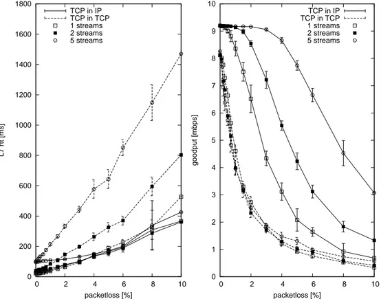
Figure 2: Performance of TCP over TCP-tunnels, application level delay (left plot) and throughput (right plot) versus loss rate on a 10 Mbit/s bottleneck com-pared with the performance of non-tunneled TCP connections traversing the same bottleneck.
Fig. 2 reports the application level throughput (goodput) and delay measured in six scenarios. Three of these, marked with dashed lines, refer to cases where TCP-tunneling is used. Different point styles indicate the number (one, two, or five) of concurrent TCP connections running through the same TCP-tunnel. In the remaining three cases, marked with solid lines, the same number of TCP con-nections share the same bottleneck, but without the tunnel. The Thrulay [12] measurement tool was used to generate traffic and to measure values. Reported goodput values are aggregates of all streams. Since Tor breaks the end-to-end TCP loop, we measure application level round trip time (RTT) instead of the usual TCP RTT throughout the paper, in order to allow comparison with Tor. Each experi-ment was run 10 times, averages and standard deviations are plotted.
Lines referring to a single connection provide a reference case that allows measuring the intrinsic overhead of the when losses are set to zero. All other measured points clearly show that, while multiplexing TCP flows on a lossy bot-tleneck allows for a better and better exploitation of the resources as the number of TCP flows increases (as taught in any book), if there is a TCP tunnel on top of the bottleneck, then, as the number of connections sharing tunnel and bottle-neck increase, the throughput is not improved, while the delay increases steadily. Sect. 2.3.1 presents the (simple) theoretical reason for this behavior.
2.2
Tor case
Tor overlay architecture is more complex than a simple tunneling. Appendix A presents a short primer on Tor, but we refer the interested reader to the Tor web-site and specific literature. First of all, its internal control mechanisms forbids to have any topology with less than three Tor hops2. Then, the ingress OP
termi-nates incoming TCP connections, building a shared, per destination-OR connec-tion which is flow-controlled with a fixed size window protocol whose window size Wf is expressed in Tor cells. These streams are transported to the
destina-tion on a chain of TLS tunnels that implements the Tor ‘telescope’. Fig. 3 depicts the simplest possible Tor topology. We set up this topology in our lab network with similar conditions to the TCP over TCP experiment. The lossy 10 Mbit/s bottleneck is between OR1 and OR2.
Fig. 4 reports goodput and application layer delay for Tor (with different val-ues of the flow control window size Wf) compared with the performance of the 2Indeed, two is the minimum number of hops needed to ensure anonymity, but Tor is devised
OP OR1 OR2 OR3
Figure 3: Minimal Tor overlay: 3 hops with one exit OR.
0 2000 4000 6000 8000 10000 12000 14000 16000 18000 0 2 4 6 8 10 L7 rtt [ms] packetloss [%] Tor, window=200 Tor, window=1000 (default) Tor, window=5000 IPpriv 1 streams 3 streams 5 streams 0 1 2 3 4 5 6 7 8 9 0 2 4 6 8 10 goodput [mbps] packetloss [%] Tor, window=200 Tor, window=1000 (default) Tor, window=5000 IPpriv 1 streams 3 streams 5 streams
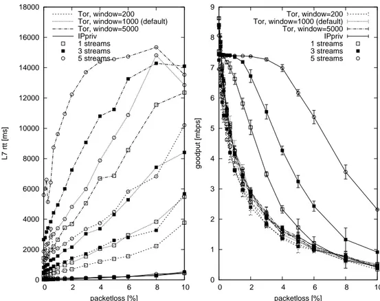
Figure 4: Performance of TCP connections in the simplest possible Tor network: application level delay (left plot) and throughput (right plot) versus loss rate on a 10 Mbit/s bottleneck, compared with the solution we propose (named IPpriv).
anonymous network architecture we are proposing in this paper in the same cir-cumstances. First of all, observe that Tor throughput is comparable with the throughput of TCP over TCP connections, while the performance of our approach is comparable with no tunneling at all. For all Wf values the Tor ‘ack
trig-ger’, i.e., the relative value of buffer filling at which the destination OR sends
a RELAY SENDME cell back to the ingress OP is set to 1/10. This has a small
influence on the goodput.
The really striking feature is however the delay (left hand side plot), which grows with both Wf and the number of tunneled connections and is, in any case,
too large to support any kind of interactive or transactional service, not to speak about real-time ones.
2.3
A simple theoretical explanation
2.3.1 TCP over TCP-tunnels
Consider the simple tunneling scenario of Fig. 1. Let τi(t) be the round trip time
of connection i crossing the tunnel, and τT(t) < τi(t); ∀i, t be the round trip time
of the tunnel itself.
Consider a generic congestion control function based on the transmitter evalu-ation of the loss probability. Without loss of generality we can consider an AIMD (Additive Increase Multiplicative Decrease) function. The same arguments dis-cussed here can be applied to AIAD (Additive Increase Additive Decrease) or any other regulation technique. Such a congestion control strategy can be expressed in terms of the following differential equation:
dR(t)
dt = αt − βR(t − τ (t))Pl(t − τ (t)) (1)
where R(·) is the connection throughput and Pl(·) is a generic loss probability
function. α and β < 1 are the additive increase and multiplicative decrease
con-stants respectively3.
We consider tunneling M layer-4 (congestion controlled) connections within the single layer-4 (congestion controlled) tunnel between N1 and N2. The
dy-namic behavior of the queue QN1 at the ingress of the tunnel at node N1 is then
3Recall that throughput R(t) and transmission window size W (t) are related by R(t) = W(t) τ(t)
the following: QN1 = max ( 0, Z t " M X i=1 Ri(t) − RT(t) #) (2) where RT(·) is the tunnel throughput and Ri(·) is the throughput of connection i.
We can now prove the following:
Lemma 1 Tunneling M congestion controlled connections into a single
conges-tion controlled tunnel, if M > 1 then the queuing delay in QN1 is unbounded
unless Pl(t) ≡ 0; ∀t.
Let first analyze the case Pl(t) ≡ 0; ∀t. In this case it is straightforward that Rmax
T ≥
PM
i=1Rmaxi guarantees that QN1 is empty since the capacity of the tunnel
is larger than the sum of all throughputs carried within it. This case might be of little practical interest, at least for large M s, but shows that without losses a transport layer tunnel can be configured to work steadily.
In presence of losses4, each lost packet will lead to a throughput reduction of a factor β for the tunnel, in addition to a period of time devoted to the recovery of the lost packet when the tunnel throughput is zero. This time lapse depends on the specific protocol, for TCP it is normally τ(t). The transmission windows of the
tunneled connections, which is the offered load to the tunnel, will normally not change at all, because the tunnel window is large and the packet is recovered with a fast retransmit in one τ(t), which is necessarily smaller than any retransmission
timeout of the tunneled connections and fast retransmits cannot be triggered. Therefore, each packet loss implies an excess traffic being offered to the tunnel and accumulating in QN1.
Let’s now analyze the evolution between losses, i.e., during a time lapse T be-tween two consecutive losses. Since the increase is linear with parameter α, it fol-lows immediately that the additional traffic offered to the tunnel is PM
i=1 αT
ET[τi(t)]
while the throughput increase of the tunnel is αT
ET[τ (t)], i.e. roughly M times
smaller, where ET[·] is the average over the time lapse T .
Since the entire life of the system is a sequence of losses and loss free periods and both events leads to an excess of traffic being offered to the tunnel, QN1 grows
without limit.
4We are not interested here in the stochastic characteristics of the loss process, nor it is
Lemma1 neatly explains the observations in Fig. 2. The left hand plot show that, independently from the loss rate, the average delay experienced at the ap-plication level grows with the number of tunneled connections, while the same number of connection on the same bottleneck do not experience a similar delay growth.
One can argue that the size of QN1 is finite, so that when the buffer fills
addi-tional losses will slow down the tunneled connections, finally leading to a stable scenario. While this observation is partially correct, it is clearly undesirable that a single loss due to real congestion in the network is transformed into multiple losses at the transport and application layer. Additionally, we can observe that, unless the size of QN1 is really small, then it will dominate τi,∀i.
In practice, to avoid the phenomenon just described, the congestion control algorithm of the tunnel should be tailored to the number of tunneled connections
M trying to guaranteeing that αT ≥ PM
i=1αi and βT ≤ E[βMi], which is not only
difficult to realize, but will also affect the overall stability and fairness of the network.
Specializing this analysis for the actual behavior of TCP, using for instance the window evolution models developed in [13, 14] does not add any insight in the problem.
2.3.2 Tor-like overlays
Consider the Tor networks described in Fig. 3. We focus on the case where a net-work level bottleneck leads to losses on the tunnel between OR1 and OR2. Once
again the origin of losses and the stochastic characteristics of Pl(t) are irrelevant
for our problem.
In Tor each TLS tunnel between ORs is terminated in the receiver OR and an unlimited5
buffer of Tor cells QOR in available. Additionally, Tor maintains an edge-to-edge window-based flow control. The size of this buffer is normally set to 1000 cells, i.e., 512 kBytes, but can be changed at installation time. Given the use of reliable overlay links (TLS) flow control is enforced with the use of non-tagged tokens: OR3sends messages which are transmission tokens, but never
acknowledge the reception of specific cells. Assume that OR3does not experience
any bottleneck in sending packets outside the Tor network, so that it can generate
5The buffer is only limited by the memory reserved for the Tor process, which is, in standard
instances of Tor, only limited by the RAM and virtual memory available, which is to our purposes practically unlimited
tokens arbitrarily fast. This assumption simplifies the description and does not change the nature of the phenomenon we are analyzing.
Let M ≥ 1 be the number of streams or flows, and (1) be the congestion
control of TLS tunnels6; we now analyze the different cases that might occur as
a function of M and Pl, although the overall behavior is fundamentally the one
of an overloaded store-and-forward system, where the delay is dominated by the dimension of the buffer in front of the bottleneck of the system.
M = 1; Pl(t) ≡ 0; ∀t: This is the simplest case, and we only have two
possible behaviors, based on the relative throughput of the OR1–OR2 tunnel (call
it RT) and the OP1–OR1 tunnel R1. If RT > R1 then the buffer QOR1 is drained
faster than it is filled, OR3 can send tokens to OP1 faster than OP1 can send cells
and no queue builds in QOR1. Otherwise if RT < R1, QOR1 will fill up until
OP1stops sending more data than it is drained, and this happens only when it runs
out of tokens. As a result the delay incurred by information in crossing the Tor network will be Dtor = Wf
RT + δ where δincludes all other delays packets incur in
the Tor network.
M > 1; Pl(t) ≡ 0; ∀t: Following the same reasoning as before we can
con-clude that in this case we have a negligible delay only if RT >PMi=1Ri, otherwise
the delay will jump to Dtor = M Wf
RT + δ. If instead of the trivial network depicted
in Fig. 3 we have a more realistic and complex meshed network, then the analysis becomes cumbersome and the result might depend on specific routing and mixing; however, in any case, each Tor tunnel will be in one of the two possible conditions defined above, and the delay of the information crossing the Tor network will be either negligible or jump to Dtor > M Wf
RT .
Pl(t) 6= 0: Indeed, since TLS tunnels are terminated in ORs and buffering
in QORj is done at the application level, the presence of losses does not change
the problem significantly, since the dominating effect is the average throughput obtained by tunnels and losses simply decrease the throughput further.
Concluding, the delay in Tor networks is due to the use of a store-and-forward technique at the application level, and its amount is strictly related to the dimen-sion of the edge-to-edge flow control window. Reducing this window below a certain (fairly larger) threshold, is however not feasible, since the throughput will be affected.
6Once more, using actual TCP behavior instead of the more general behavior described by (1)
2.4
Analysis insights
The analysis above, both for Tor and for TCP-over-TCP tunneling is simple to the point of being trivial, but explain very well the observed performance impair-ments.
Indeed, we observed and explained two different phenomena: one related to nesting of TCP-like closed loop congestion control mechanisms, and the other one related to the use of a store-and-forward technique with large buffers and loose flow control. Both phenomenon are not new to science, being it well known in the theoretic control community that nested control loops may lead to instability and in the networking community that store and forward techniques with large buffers induce long delays.
These performance issues appear to be inherent to the use of transport-level tunneling, and not related to tuning or implementation problems. Both problems can be easily solved using tunneling at the network level and not at the transport level. In the following we present a solution for anonymous networking based on IPsec, preserving Tor-like anonymous properties yet solving the performance impairments.
3
NAT-based forwarding for anonymous overlays
We propose to improve the data forwarding in anonymous overlays7 taking into
account the following three key challenges:
• No impact on native end-to-end congestion control. We believe (and in this
we found full support in the recent paper [15]) that anonymous networking should not be overloaded with cross-layer functionalities, but should sim-ply provide support for anonymous packet delivery. It should seamlessly support, without affecting or breaking them, the native transport-layer op-eration of supported connections.
7It is not a goal of this paper to describe a new complete architecture for anonymous
network-ing. Indeed, this is composed by several components, such as overlay management through direc-tory servers, routing path selection and anonymous path setup signaling, anonymity mechanisms such as packet batching and traffic covert, etc. Our goal is here restricted to describe a solution for performance effective data forwarding. We believe that it is easier (although not nearly trivial) to adapt already existing anonymous networking frameworks to forward the information data as here proposed, rather than redesign from scratch a new architecture on top of such a functionality.
• IP layer operation. As a networking functionality, an anonymous network
should directly operate on IP packets. As such, it should seamlessly support any traffic carried on top of IP packets.
• standard-based operation. We believe that any new networking paradigm
should build, if technically possible, on already existing and widely de-ployed standards.
For the sake of clarity the next subsections we assume that: i) paths are pre-established, and ii) tunneled packets are not encrypted. The solutions needed overcame these assumptions are presented in Sect. 4.
3.1
NAT as anonymity mechanism
The Network Address Translation functionality (and specifically the standard state-ful NAPT [16]) is an effective and performance-efficient anonymization mecha-nism for what concerns the source address information.
Originally, the need for IP Address translation arises when a local network uses private IP addresses which are not valid over the Internet. The need for Address and Port translation (NAPT) further arises when the number of avail-able public IP addresses is lower than the number of private IP addresses. Stan-dard NAPT supports most of the IP based protocols. To provide the ability to route return packets to the proper source, NAPT keeps a binding from the tuple
<private address, private TCP/UDP port> to the tuple <assigned address,
as-signed TCP/UDP port>. This binding is determined when the outgoing session is initiated.
NAT may as well translate public IP addresses. In doing this, it can be con-sidered as a widely deployed technique for achieving IP layer anonymity. In fact, without having access to the binding information, there is no way, for a public Internet Server, not only to discern which specific IP address is associated to a received NAT-ted request, but also to understand whether the request is originally NAT-ted or not.
IP layer anonymity is not sufficient to guarantee privacy, and the user identity may be disclosed from higher layer information. This is a well known issue which affects any anonymous networking approach. Specific filtering solutions, such as Privoxy [17] for HTTP, have been designed to remove private information from application layer requests.
3.2
NAT as a “label-switching” mechanism
NAT can also be considered as a form of label-switching applied to the return path. This statement, which might perhaps seem questionable at a first look, is indeed self-evident if we analyze what happens to the return packets. In terms of routing, these return packets undergo three subsequent steps. First, packets are delivered from the server to the NAT device. In this step, the final destination is that of the NAT device. Second, NAT provides what can be considered to all extents a label switching functionality: it switches traffic arriving from an inbound “IP pipe”, namely the server-NAT pipe, to an outbound pipe, namely the NAT-source pipe. This is accomplished by changing the “label” used in the server-NAT pipe (namely, the destination IP and TCP/UDP port address) into a new label that identifies the NAT-source pipe (namely the source IP and port addresses). Third, IP packets whose destination IP/port addresses have been properly changed are IP-routed towards the source.
Although obvious to most (or all) readers, we remark that this operation does not break the end-to-end scope of the transport protocol. Even if the sockets are identified by a different tuple at the two ends, all transport layer functionalities (including congestion and flow control) remains implemented on an end-to-end basis.
3.3
Anonymous routing through NAT extensions
The considerations separately provided in the previous two Subsections can be integrated to achieve, at least in principle, anonymous routing. We say “in princi-ple”, as in practice the level of protection provided by the approach described in what follows is not nearly close to prevent from attacks against anonymity as well as denial of service attacks, and a more elaborate solution, as presented in Section 4 is needed.
Using NAPT translation extended also to destination IP/port addresses (i.e., DNAT), packets originated by a source node S with source port PS, may be
anonymously delivered to a destination node D with destination PD through a
pre-established overlay path (say three overlay routers: an “entry” router A, an “intermediate” router B and an “exit” router C) as follows:
1. packets are sent from S to A to an anonymous delivery service running over a dedicated port PANON. Router A retrieves from a pre-established NAPT table, an entry configured for S in terms of i) IP address of the next overlay router, B, and ii) source port LAto be used as label;
2. when the packet originated from node A with port LA arrives to node B
under port PANON, the router looks up the binding associated to the pair
< A, LA >, retrieving node C and the source port value LB to be used as
label, and accordingly NATs and delivers the packet;
3. finally, node C will find that the binding associated to the pair < B, LB >
is the destination node D and the destination port PD;
4. return packets are then routed back to the source as in the case of ordinary NAPT. Note that while the NAPT bindings for the forward path must be pre-configured, this is not necessary for the reverse path.
We finally remark that, as discussed for the case of the single NAT case, also in the case of a chain of NATs the end-to-end scope of the transport protocol is not broken, and as such this approach does not suffer of the performance drawbacks discusses in Section 2.
3.4
Shortcomings
The approach described so far is highly efficient and based on standard network-ing mechanisms (the NAPT operation described before can be supported over legacy routers), and helps understanding the basic principles of the framework we promote; however it suffers several shortcomings.
First, the level of protection is insufficient and even basic attacks would break anonymity. An external observer could in fact trivially confront the payload of the packets entering and exiting a node, and when they do match, reconstruct the binding rule enforced by the node, and hence the path. Similarly, colluding overlay routers could do the same: for instance if the entry node (which knows the real source address) and the exit node (which knows the real destination ad-dress) compare the delivered packets and find matching payloads, the association between source and destination addresses would be reconstructed.
Second, the proposed NAT-based approach suffers of scalability problems. Es-pecially in the backbone links, the number of available source ports to be used as labels might be insufficient to carry the possibly large number of flows to be mul-tiplexed.
Third, the usage of a known port PANONis subject to denial of service attacks, as well as many other attacks (e.g., injection of spoofed IP packets, etc).
S A entry node B C exit node Overlay tunnel Onion encapsulation D
Figure 5: Nodes of a circuit-based anonymous routing overlay connected by over-lay tunnels. The onion encapsulated tunnels (telescope) of one circuit are shown. aware of), but would also need to be specifically designed for setting up labels consistently across the path, in addition to signaling the next hop information at each router.
4
IPsec forwarding in anonymous overlays
Anonymity is impossible to achieve without proper encryption. Not only packets entering and exiting an overlay router should be at least8protected through distinct
per-overlay-hop encryption, to protect them from analysis carried out by external observers, but encryption should also protect the contents of the packets from inspection (and related deriving attacks) by overlay routers.
In the proposed framework, for reasons that will be clarified in what follows, these needs are separately accomplished by i) encrypted tunnels deployed between pairs of overlay nodes, and ii) re-encryption mechanisms applied by each node over every forwarded packet. Note that this design inherits the same ideas of anonymous overlays such as Tor, Tarzan or Freedom; the difference resides in the architectural placement of tunnels and encryption. In both cases, our design approach is to reuse existing standards, specifically IPsec, and hence achieve an
8Encryption, albeit being an essential component of any anonymous routing mechanism, is not
sufficient to defend against all forms of statistical analysis attacks. State of the art Mix networking solutions, such as packet reshaping, batching, traffic marking and so on, can be integrated in our framework without requiring a re-think of the whole system operation. As such, these issues are out of the scopes of the present paper.
operation that can be supported over ordinary routers. As sketched in Fig. 4, this is accomplished by i) deploying long-term overlay point-to-point IPsec tunnels between pairs of overlay routers, and ii) inside these tunnels, build short/medium-term IPsec “telescopes”, namely a series of nested IPsec encapsulations, devised to carry the data delivered by a single client.
Throughout the following subsections, we assume the reader to be familiar with both the IPsec architecture [18] as well as the related family of standards, and especially ESP [19] and IKEv2 [20].
4.1
IPsec telescopes
Let S be a source node, and A, B, C three subsequent overlay routers along the path. We define an IPsec telescope as a sequence of nested IPsec ESP tunnels constructed as follows.
• S establishes a first IPsec ESP tunnel with A;
• Using this tunnel as first hop, S establishes a second IPsec tunnel with B.
This implies that this second ESP encapsulation is delivered as encrypted payload in the first tunnel; once the end of the first tunnel is reached, the IPsec ESP packet is delivered toward node B. The fundamental property of such tunnel is that it uses A as the source address for the IP header of the ESP packet.
• Similarly, a third IPsec ESP tunnel is created between the source S and the
last overlay node C. The IP source used is in this case is that of B, and the path used to reach node C is through the previously created tunnels.
As illustrated in Fig. 4, this operation implements an onion of IPsec ESP encap-sulations. On the link connecting S to A, an IPsec ESP packet will deliver, as encrypted payload, a second IPsec ESP packet. This will be extracted when the first packet exits the tunnel from S to A: at this stage the next destination B ap-pears, and the original source node address is not disclosed because this second IPsec ESP packet is constructed with A as its source IP address. And so on until the final IP packet is de-wrapped and delivered to the end destination starting from
C (and having set C as the origin address).
This operation allows the deployment of a fully standard transformation of the packet at each node. Actually, rather than re-encryption, an IPsec ESP wrap is removed at every hop (and the corresponding decryption is performed), and hence
the new packet payload will be different. This is perhaps a costly operation in terms of resulting overhead. Every extra hop requires to add a level of tunneling, hence an extra 20 bytes IP header plus, in general, 24 extra bytes of ESP header, which may be reduced to 12 by using only ESP encryption without authentication. However it accomplishes, in a fully standard way, the task of transforming the packet at each overlay router.
In terms of anonymous data forwarding, this operation is completely identical to the previously described NAT-based approach for the forward path. Indeed, at every step it appears that both the source and the destination IP addresses changed. However, this NAT-like change of IP source address is not actually performed by a NAT function inside the node, but it is prepared beforehand by the source node. As such, there is no need to pre-establish NAT tables at each node. The required state information is instead encoded in the IPsec databases, which can be established dynamically using IKE signaling.
NAPT is still needed in the forward path at the exit node, but no pre-established state is required. The exit node should make the <source port, destination port, destination address> 3-tuple unique by changing the source port in case several anonymous clients try to communicate with the same server using the same source and destination port numbers.
In the forward path routing is based on IP addresses embedded in internal IP headers, and therefore it is straightforward. Support routing in the backward path and deliver return packets from the destination D to the source node requires some extra tricks. We propose to rely on a somewhat creative extension of stateful NAT-ting. The key idea is the following.
In the backward path, the overlay node should recognize the incoming packet as belonging to a given telescope, and encapsulate it in the next telescope accord-ingly. “Entry” (A) and “intermediate” (B) overlay routers can easily identify the telescope based on the unique SPI (Security Parameters Index) of the outermost encryption of the incoming packet9.
E.g., in the case of B, the packet coming from C will already be encrypted in the third tunnel, and its SPI is unique for the given telescope. Based on the SPI, using an appropriately configured security policy, B selects the next telescope layer and encapsulates accordingly.
The case of the “exit” node (C) is more complex. Here the incoming packet is a response from an ordinary server, therefore it is not ESP encrypted and not
9Uniqueness of the SPI is guaranteed among the SPIs used between C and B, by enforcing it
identified by any SPI10.
The connection is identified by the stateful NAT, but then it should be encap-sulated in the corresponding telescope. The key problem is creating the binding between the NAT connection state information and the IPsec SA. We discuss two possible solutions:
• extension to stateful NAT: in this case the reverse NAT process directly
triggers the IPsec encryption. This integration between the NAT module and the SPD is possible in some routers through packet marking, but it is not standard. Therefore we present a second option that resolves the binding problem through standard means.
• binding through private IP address: In this case C assigns a private IP
ad-dress SC to S during telescope setup. The address should be unique only
among the addresses assigned by C. Such an assignment is supported by IKEv2. While constructing the packet, S uses this address as source address in the innermost (end-to-end) IP header. SC creates the necessary binding
as follows: in the forward path, the NAT applied in C replaces SC by the
public address of C, while in the reverse path it restores SC. Being unique,
an SP can be bound to SC by placing it as the source address in its
selec-tor (actually, this binding is automatically created in assigning the address during IKE negotiation).
4.2
Overlay tunnels
Long-term overlay tunnels protect against external attackers by multiplexing all the telescopes that have a section between the given two overlay nodes in one encrypted tunnel. Without this, the SPI value of the outermost layer of every telescope is seen by an observer, which allows the differentiation of individual streams and leads to easy matching or statistical traffic analysis attacks.
The disadvantage of overlay tunnels is the extra overhead added, as well as an extra decryption and encryption operation in each overlay hop. Furthermore, if TCP based tunnels are used like in the case of Tor, it leads to the performance degradation demonstrated in 2.3.1. By using IPsec overlay tunnels, the presented system is free of this latter performance bottleneck.
A positive side-effect of IPsec overlay tunnels is that they ensure delivery of packets from one overlay node to another, independent of the source and
des-tination IP addresses of the internal IP header. In fact, between A and B, the packet should travel with A as source address. Without overlay tunnels, this can be achieved either by filling the source IP address with A address already in S, or by NAT-ting the packet in A after decapsulation from the S–A telescope tunnel. Both of these solutions have shortcomings: the former breaches the principle of generating IP headers only with own IP address as source, the latter introduces NAT traversal problems during IKE tunnel setup [21].
If instead overlay tunnels are used, the IP header of the overlay tunnel (the external IP header) contains A as source, while the source addresses inside the overlay tunnel can be chosen freely. This allows the use of the same private ad-dress assignment we have introduced for the exit node also for intermediate and entry nodes: Every intermediate node can be an exit node as well, which makes it possible an incremental IKE-based telescope setup.
4.3
A proposal for IKE-based telescope setup
Although our current implementation is restricted to data path operation, we briefly discuss how standard IKEv2 can be used to set-up the telescopes incrementally.
Designing a proprietary signaling protocol, as it was done in Tor (and to the best of our knowledge all other anonymity systems) is clearly possible. Indeed, Tor’s signaling can easily be adapted to our case with small modifications, namely changing the role of circuit identifiers to that of private IP addresses. The chal-lenge we face however is different, we would like to design the signaling needed for telescope setup using standard IKEv2 message primitives. The introduction of such a signaling would mean that IKEv2 compliant routers can take on the role of ORs not just on the data plane, but also on the signaling plane, without even the need for an external entity handling signaling.
In what follows, we discuss incremental telescope setup using standard IKEv2 for the complete case, when overlay tunnels are employed and private IP addresses are assigned in each overlay node.
The use of IKEv2 presents the following challenges:
S.1 negotiation messages should not use S as their source address, instead these must be anonymized by the existing part of the telescope.
S.2 IKEv2 communicates the address of the negotiating parties as part of the Traffic Secector during negotiation. We should make sure that the address is not communicated.
S.3 we should make sure that no other identifiers of S are communicated during the negotiat.
S.4 IKEv2 can automatically figure-out if a NAT device is in the path and en-force UDP encapsulation according to the NAT-T specification. We would like to avoid the use of UDP encapsulation.
S.5 The state generated during negotiation should enforce backward path rout-ing.
To resolve S.1, negotiation is done incrementally. Establishing the first tunnel between S and A is trivial. Here the use of S does not present any problem, the first OR must know this address for proper routing. During the negotiation, an internal unique private IP address SA is assigned to S by A using the standard
Configuration Payload (CP) option.
While negotiating the IPsec tunnel between S and B, S sends out IKE packets using the source address (SA) assigned to him by A. It also uses SAin the Traffic
Selector (TS) payload, thus avoiding S.2. Moreover, S should also remain anony-mous during key negotiation, therefore it uses one side authentication as defined in [22]. This also resolves S.3.
Packets used during the negotiation with B are first destined (in their outer IP headers) to A. After decapsulation in A, however, the remaining part of the packet is destined to B. Therefore it is encapsulated automatically in the A-B overlay tunnel. This also means that no source NAT-ting is needed in A, the packet can keep its source address of SA. With this, we avoid the problem of S.4
Finally, we should ensure that backward path routing of packets from B is cor-rectly done in A. This should hold both for packets sent during IKEv2 negotiation between S and B, as well as for later data packets. Backward path routing in A is based on the unique SAbeing the destination address. Since SAis assigned
us-ing the Configuration Payload mechanism, the required bindus-ing is automatically created.
B also assigns a unique private IP address (SB), and the process continues
incrementally till the required telescope length is reached.
5
Performance
We have implemented the data plane of the architecture we presented in the previ-ous sections, called IPpriv, over the 2.6 Linux kernel. We should emphasize that
no modifications to the kernel code were necessary, the architecture uses exist-ing IPsec functions to achieve anonymous routexist-ing. The implementation merely configures the routing and IPsec behaviour through standard APIs in a way that anonymous routing is achieved.
The performances reported in Sect. 2 refer to this implementation. Provided an IKEv2 signaling framework, the system can also make use of standard commercial routers.
To evaluate the performance of IPpriv, we have conducted three types of mea-surememts:
• first, in order to get a detailed picture on how different architectural choices
influence data path performance, we have measured performance using well known througput and latency measuremt tools in a controlled environment. For this, we have constructed an isoloated testbed in our laboratory with configurable network characteristics;
• second, to get a more precise picture of how IPpriv performs in real
en-vironemts, we were measuring application level performance, namely (in-spired by the most frequently used service) web page download times. Mea-surements were conducted both in the local testbed by connecting its exit node to the Internet, as well as in a testbed forming a real overlay over the Internet;
• finally, we have also performed measuremnts to verify the stability and
5.1
Synthetic performance benchmarks
The performance comparision presented in Fig. 4 plots alone justifies our work, however, some deeper inspection is useful.
Fig. 6 reports experiments with Tor and IPpriv as the bottleneck bandwidth changes from 0 to 10 Mbit/s with a random loss rate of 3%. Similar experiments with other loss rates yields coherent results. In the goodput (lower) plot, we report Tor only with a window size of 1000 in order not to clutter up the figure, since all other Tor veriants had equal goodput.
IPpriv goodput exploits all the resources (lower plot) as soon as a few con-nections are multiplexed on the IPsec tunnels; only where there are just one or two connections then the loss rate diminishes the exploitation of resources. It can clearly be seen that even in the case of one stream, IPpriv largely outperforms Tor in these conditions, as soon as the available bandwidth grows over 2 Mbit/s. Tor, independently from the flow control window Wf, is not able to achieve high
resource utilization.
Besides, and most important, in the case of IPpriv, the application level delay (upper plot, measured on 1024 bytes chunks) becomes negligible as soon as the bandwidth available is sufficient, and remains negligible even if many connections are multiplexed together. Tor introduces a delay that, although it diminuishes with the reduction of the flow control window, is always above one second. Moreover, as soon as the number of connections increases the delay jumps to several seconds.
0 2000 4000 6000 8000 10000 12000 14000 16000 18000 20000 0 2 4 6 8 10 L7 rtt [ms] bottleneck bandwidth [mbps] Tor, window= 200 Tor, window=1000 (default) Tor, window=5000 IPpriv 1 streams 5 streams 0 1 2 3 4 5 6 7 8 0 2 4 6 8 10 goodput [mbps] bottleneck bandwidth [mbps] Tor, window=1000 (default)
IPpriv 1 streams 5 streams
Figure 6: Performance of Tor and IPpriv as a function of the bottleneck capacity with 3% loss rate: application level delay (upper plot) and throughput (lower plot) for 1 and 5 tunneled connections.
Web server www.cnn.com UniRoma2
ORInternet,2
UniTrento
Client ORlocal,1 ORlocal,2 ORlocal,3
ORInternet,3 UniBute ORInternet,1 Web Server (local copy) direct co nnection to CNN Inte rnet test bed local testbed to local copy
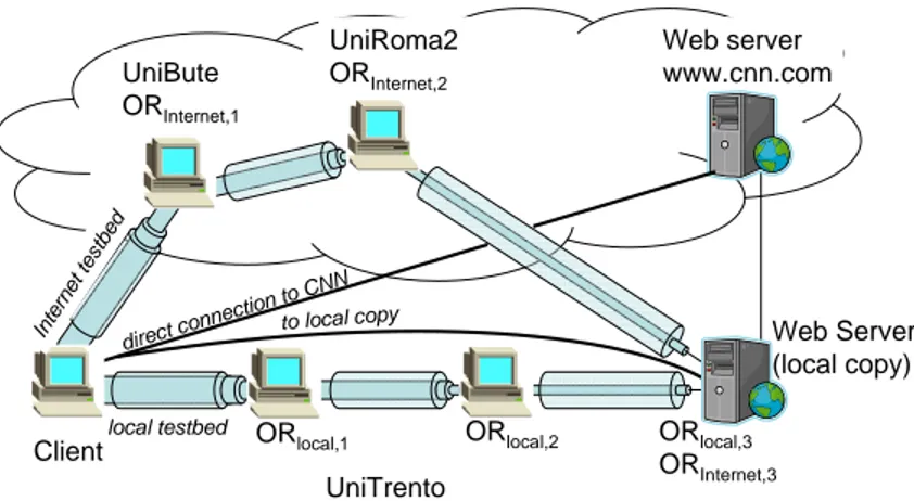
Figure 7: Testbed configuration and experiment setup
5.2
Web page download performance
Fig. 7 describes the measurement setup. We compare the performance of Tor and our IPsec-based anonymous networking solution. Protecting privacy and enforc-ing anonymous networkenforc-ing implies performance degradation. To evaluate this “cost”, we choose two measures: web page download time and traffic overhead, the first one being the price a user has to pay for anonymity, while the second measuring the cost for the network to support it. As an example we have selected the download of the main page of CNN with Firefox, but other web-pages, the use of other protocols (e.g., ftp or POP/smtp for e-mail), or the use of different browsers do not change the scenario, yielding similar results.
Our goal is to verify if the IPsec based solution can perform better than Tor, a service which has already about 200.000 users despite its performance bot-tlenecks, which are normally described as a price which must be paid to have anonymity. We have configured IPsec tunnels with the same cyphers as used in Tor (AES-CBC 128-bit encryption and SHA-1 data authentication) in order to guarantee a fair comparison between the systems and be sure that differences are not due to the different efficiency of the encryption algorithm.
To better understand the impact of the overlay networking and the anonymiza-tion ‘price’ we have used two sets of overlay nodes for our tests: a circuit of three nodes in our lab (local testbed); and a circuit of three nodes in different Euro-pean universities (Internet testbed). In both circuits, the exit node was the same router in our University, therefore the last unencrypted part of the path to CNN was always the same. In both circuits we had Tor as well as IPsec-based
0 100 200 300 400 500 600 700 800 900 traffic [kilobytes]
local copy of CNN main page www.cnn.com direct connection
IPsec, local testbed Tor, local testbed IPsec, Internet testbed Tor, Internet testbed
Figure 8: Traffic received to complete the web page download
mous routing installed11, thus having five different cases, including the direct, non anonymous download.
Additionally, to evaluate the performance also in an “ideal” scenario, where the Internet does not interfere with the download speed, and there is no need for an exit node, we have prepared a local copy of the CNN main page on our own server, having five more cases marked with local copy. Notice that the on-line CNN page is dynamic and changes continuously, while the local copy was always the same (indeed, it turned out to be a page slightly larger than the average), so that on-line and local results are not directly comparable.
The direct connection results refer in both scenarios to non anonymous down-load of the same information, thus representing the baseline performance of the service. All downloads were repeated 10 times averaging the results; error bars refer to ± the standard deviation.
Fig. 8 shows the total amount of traffic generated in each scenario. Privacy protection with onion routing induces significant overhead in bytes: around50%
for both solutions. The price of privacy protection is relatively high, but not ex-cessive, and it can be applied selectively on sensitive traffic. From the network perspective, further overhead is induced by routing packets over multiple overlay links instead of using shortest path routing. As we already discussed, this is a shortcoming of all current anonymous networking solutions.
11To achieve comparable results, our private Tor network was not connected to the global Tor
0 5 10 15 20 25 30 35 40
download time [sec]
local copy of CNN main page www.cnn.com direct connection
IPsec, local testbed Tor, local testbed IPsec, Internet testbed Tor, Internet testbed
Figure 9: CNN web page download time
Figure 9 shows average download times for all cases. With no bottlenecks (local testbed - local copy), layer 3 operation is clearly much faster than Tor. There is almost no delay that can be ascribed to IPsec-based OR operation, in contrast to Tor where the average download time increases threefold (from 1 s to 3 s). Tor’s performance degradation is rooted in architectural choices and the use of TLS tunneling in each overlay hop, and it is not due to bad implementation. The Internet testbed obviously increases RTT and thus download time, since packets are routed around Europe to distribute trust to different countries. Here Tor’s disadvantage grows significantly (24 s vs. 6 s with IPsec, again threefold), having a page download time clearly noticeable by the user and thus annoying.
Looking at downloads directly from CNN through the local testbed (right side of figure 9), our IPsec based solution increases the download time compared to direct download by roughly 50%. Surprisingly, Tor over the local testbed is slower (14 s) than IPsec over the Internet testbed (10 s), indicating that the performance bottlenecks are to be sought for in Tor itself and not in the Internet. Finally, the performance of Tor with the Internet testbed makes it almost unusable with interactive services.
5.3
Scalability and stability
In order to be able to perform CPU load measurements and to avoid bandwidth bottlenecks between the overlay routers, we were using four identical 2.6GHz Pentium4 machines with 512 Mb of RAM, connected by a full-duplex gigabit LAN.
First, we analyze goodput and CPU load characteristics in this controlled test environment. When nodes were running at full speed, we have measured 44 Mbits/s with IPsec when the client was sending data and 47 Mbits/s when it was receiving data. With Tor, achievable bandwidth was 24 and 16 Mbits/s respec-tively. In all cases the the client was the weakest link in the chain, having the highest CPU usage among the nodes.
In order to measure the CPU load of every node as a function of goodput, we needed a trick: we lowered the CPU freqency of the node under test to 650 Mhz, this way it became the weakest in the circuit. Figure 5.3 shows the CPU utilization of each node as a function of the application level traffic (obviously achieved goodput is lower due to the CPU slowdown). We have used the Linux traffic control framework with a token bucket to limit bandwidth, the thrulay tool to generate symmetric bi-directional traffic and sysstat to measure CPU utilization.
The resource usage of the client and of OR3 is different from other nodes for several reasons: they serve as traffic end points, they perform different number of encryption/decryption operations and they should also handle end-to-end SHA1 authentication.
Figure 5.3 shows significant performance improvements over Tor, however we should not overestimate the importance of these measurements. Even if huge dif-ferences can certainly be seen for the current implementations, part of this might easily be due to factors we can’t control in the test environment, e.g. differences in the underlying crypto implementation.
Rather, we would like to emphasize differences due to system architecture design. In the case of IPsec, all of the measured CPU utilization was in kernel space. In the case of Tor, most of the CPU time was spent in user space (around 90% user space, 10% kernel space) which might explain some of the performance differences: Tor involves much more copying, context switching and buffer man-agement, which all takes precious CPU time.
In our system, kernel space operation is possible since the data path is handled entirely at the IP level, in contrast to the application level processing applied by Tor. This allows for new deployment models, as we have discussed earlier. It should be emphasized that no changes are needed to the kernel, any operating
0 2 4 6 8 10 12 14 16 18 20 0 10 20 30 40 50 60 70 80 90 100 goodput [megabits/s] CPU utilization [%] IPsec Client Tor Client IPsec OR2 Tor OR2 IPsec OR3 Tor OR3
Figure 10: CPU utilization as a function of goodput. Client, intermediate node and exit node are studied. (Entry node showed identical performance to an inter-mediate node, therefore it is omitted from the figure )
system (or router in general) that supports IPsec tunnels can be configured to work as an overlay router.
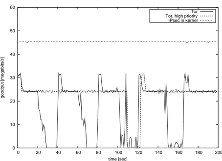
Kernel space operation also ensures that the data path of an overlay router is not affected by user space processes. Figure 5 shows data path performance when OR2 is busy running other applications (we use the stress program to load the overlay router).
Stress was running from the 20th second of the connection in OR2, putting high load on the CPU for 20 seconds. The cycle continued with 20 seconds periods of no load and 20 seconds of different types of load: I/O, memory subsystem and finally load on the HDD (in each case, stress was configured to create 20 processes). Routing performance is highly affected in the case of Tor, while it stays stable for the IPsec based solution. This is of course achieved at the price of slower application execution, which should not be a problem in the case of a router.
To deepen our measurement, we were also running Tor with increased priority (renice -20). As shown on Figure 5, load on the memory subsystem still affects Tor routing performance heavily. Same results were achieved with other prioritization
0 10 20 30 40 50 60 0 20 40 60 80 100 120 140 160 180 200 goodput [megabits/s] time [sec] Tor Tor, high priority IPsec in kernel
Figure 11: Routing performance under heavy load, showing benefits of kernel vs. user space operation
6
Conclusions
Anonymous networks, as well as VPNs, for the protection of users’ privacy are already standard pieces of the global Internet. Available solutions for anonymiza-tion and many VPN too, are however plagued by unacceptable performance degra-dation.
In this work we have shown that performance impairments are neither intrinsi-cally related to anonymization, nor due simply to poor implementation, but instead they are rooted in the architectural choice of building overlays on top of transport layer, flow and congestion controlled tunnels.
Given the above observation, we have proposed an entirely new architecture for anonymization based on the extension of standard IP-layer tools and protocols. This architecture ensures the same level of anonymity guaranteed by state-of-the-art solution like Tor and at the same time contains performance degradation (in terms of application level throughput and delays) to a small fraction of the perfor-mance obtained by direct, non anonymized flows.
Experiments run on a Linux-based implementation of the proposed architec-ture shows that in standard operating conditions the user-perceiver performance of our systems hardly distinguishable form a standard network, while the penalty paid by Tor and similar systems, just for the choice of using TLS tunnels, makes it impossible to use real-time and also interactive applications on anonymous net-works, hampering the diffusion of these systems.
References
[1] David Chaum. Untraceable electronic mail, return addresses, and digital pseudonyms. Communications of the ACM, 4(2), February 1981.
[2] David M. Goldschlag, Michael G. Reed, and Paul F. Syverson. Hiding Rout-ing Information. In R. Anderson, editor, ProceedRout-ings of Information HidRout-ing: First International Workshop, pages 137–150. Springer-Verlag, LNCS 1174, May 1996.
[3] Roger Dingledine, Nick Mathewson, and Paul Syverson. Tor: The second-generation onion router. In Proceedings of the 13th USENIX Security Sym-posium, August 2004.
[4] Philippe Boucher, Adam Shostack, and Ian Goldberg. Freedom systems 2.0 architecture. White paper, Zero Knowledge Systems, Inc., December 2000. [5] Michael J. Freedman and Robert Morris. Tarzan: A peer-to-peer
anonymiz-ing network layer. In Proceedanonymiz-ings of the 9th ACM Conference on Com-puter and Communications Security (CCS 2002), Washington, DC, Novem-ber 2002.
[6] Michael Reiter and Aviel Rubin. Crowds: Anonymity for web transactions. ACM Transactions on Information and System Security, 1(1), June 1998. [7] Sharad Goel, Mark Robson, Milo Polte, and Emin Gun Sirer. Herbivore: A
Scalable and Efficient Protocol for Anonymous Communication. Technical Report 2003-1890, Cornell University, Ithaca, NY, February 2003.
[8] Steven J. Murdoch and George Danezis. Low-cost traffic analysis of Tor. In Proceedings of the 2005 IEEE Symposium on Security and Privacy. IEEE CS, May 2005.
[9] Kevin Bauer, Damon McCoy, Dirk Grunwald, Tadayoshi Kohno, and Dou-glas Sicker. Low-resource routing attacks against tor. In Proceedings of the Workshop on Privacy in the Electronic Society (WPES 2007), Washington, DC, USA, October 2007.
[10] Openvpn. http://openvpn.net/.
[11] N. Williams and M. Richardson. The Future of Virtual Private Networks. White paper, NeoAccel, 2006.
[12] Thrulay: THRUput and deLAY network capacity tester.
http://shlang.com/thrulay/.
[13] Vishal Misra. A fluid-based analysis of a network of aqm routers supporting tcp flows with an application to red. In Proc. SIGCOMM 2000, 2000. [14] Chris Hollot, Vishal Misra, Don Towsley, and Wei bo Gong. A control
theoretic analysis of red. In In Proceedings of IEEE Infocom, pages 1510– 1519, 2001.
[16] P. Srisuresh and K. Egevang. Traditional IP Network Address Translator (Traditional NAT). RFC 3022 (Informational), January 2001.
[17] Privoxy. http://www.privoxy.org/.
[18] S. Kent and K. Seo. Security Architecture for the Internet Protocol. RFC 4301 (Proposed Standard), December 2005.
[19] S. Kent. IP Encapsulating Security Payload (ESP). RFC 4303 (Proposed Standard), December 2005.
[20] C. Kaufman. Internet Key Exchange (IKEv2) Protocol. RFC 4306 (Proposed Standard), December 2005.
[21] B. Aboba and W. Dixon. IPsec-Network Address Translation (NAT) Com-patibility Requirements. RFC 3715 (Informational), March 2004.
[22] N. Williams and M. Richardson. Better-Than-Nothing-Security: An Unau-thenticated Mode of IPsec. Internet-Draft draft-ietf-btns-core-07, Internet Engineering Task Force, August 2008. Work in progress.