Universit`a degli Studi di Pisa
FACOLT`A DI INGEGNERIA
Corso di Laurea Specialistica in Ingegneria Informatica
Tesi di Laurea Specialistica
Design and development of a nesC to C language translator
for the Erika real-time kernel
Candidato:
Luca Santocono Relatori:Prof. Paolo Ancilotti
Prof. Giuseppe Lipari Prof. Giuseppe Anastasi
Abstract
The nesC programming language is an extension to the C language designed and developed specifically for TinyOS, an operating system for wireless sen-sor networks. For that reason it tries to reflect TinyOS’s event driven and component based architectural model by offering constructs and statements that can be directly mapped to TinyOS components or primitives. Conse-quently, the existing nesC compiler, which is actually more a translator then a compiler, since the transformation to a low level language is done by the underlying C compiler, is tailored for a use with TinyOS.
This work tries to decouple nesC from TinyOS with the design and re-alization of a translator which has a double purpose. On the one hand it translates nesC to C and on the other hand it substitutes TinyOS constructs and primitives with Erika ones. Therefore, apart from being a language translator, the resulting software of this work can be seen as an operating system translator as well.
Erika is a wireless sensor network operating system that adds cutting edge real time scheduling algorithms to an OSEK/VDX compliant kernel. The OSEK/VDX standard guarantees to an operating system hardware, ap-plication and network independence. To facilitate the porting of new and existing applications to the Erika operating system the present language and operating system translator has been realized from scratch with the help of the JavaCC parser generator which generates appropriate Java classes from a nesC language grammar specification.
v For my father, his infinite patience, his answers that he always had for any question.
Contents
1 Introduction 1
1.1 Problem Definition . . . 1
1.2 State of the art . . . 2
1.2.1 nesC TinyOS . . . 2
1.2.2 nesC Eclipse plug-ins . . . 3
1.2.3 MeshC . . . 3
1.2.4 nCUnit . . . 3
1.3 Innovations introduced by this thesis . . . 3
1.4 Terminology . . . 4 1.5 Thesis structure . . . 5 2 TinyOS 7 2.1 Design . . . 7 2.2 Hardware Abstraction . . . 8 2.3 Scheduler . . . 9 2.4 Memory model . . . 10 2.5 Components . . . 11 2.5.1 Commands . . . 12 2.5.2 Events . . . 12 2.5.3 Tasks . . . 13 3 Erika 15 3.1 OSEK/VDX compliant design . . . 16
3.2 Architecture . . . 18
3.3 Scheduler . . . 19
3.4 Memory model . . . 19
3.5 RT-Druid . . . 20
3.6 nesC to OIL translations . . . 22
3.6.1 task . . . 22
3.6.2 Timer.fired . . . 22 vii
viii CONTENTS
4 The nesC language and its C translation 25
4.1 Component specification . . . 25
4.2 Modules and Interfaces . . . 28
4.2.1 Split phase operations . . . 28
4.2.2 nesC Keywords and their translation . . . 29
4.3 Configurations and Wiring . . . 34
4.3.1 Implicit Wiring . . . 37
4.3.2 Parameterized Wiring . . . 38
5 General compiler design 41 5.1 Front end . . . 41
5.2 Back end . . . 43
5.3 JavaCC - a parser generator . . . 44
5.4 JJtree - a parse tree generator . . . 44
6 Architecture 47 6.1 Introduction . . . 47
6.2 Software Requirements specification . . . 47
6.2.1 Users of the software . . . 47
6.2.2 Use cases . . . 48
6.2.3 Requirements definition . . . 49
6.2.4 System requirements specification . . . 49
6.3 System Design . . . 51
6.3.1 Activities . . . 51
6.3.2 Realization of a nesC to C translator . . . 52
6.3.3 Realization of a nesC library for Erika . . . 59
6.3.4 Version control . . . 60
6.3.5 Testing software . . . 60
6.3.6 Selecting a cross compiler for target platforms . . . 61
6.4 Software design . . . 61
6.4.1 nesC to C translator design . . . 61
6.4.2 Realization of a nesC library for Erika . . . 65
6.5 Implementation details . . . 66
6.5.1 The front end . . . 67
6.5.2 The parser . . . 67
6.5.3 The C and OIL code generators . . . 67
6.5.4 The symbol table . . . 67
6.5.5 XML parsers . . . 68
6.5.6 The nesC entity Objects . . . 68
CONTENTS ix
7 Installation and Using 75
7.1 Software Requirements . . . 75
7.2 Installation . . . 76
7.2.1 Installation of nesC-Erika . . . 76
7.3 Using - Sample compilation on an AVR target . . . 77
8 Experiments 85 8.1 Target Hardware . . . 85
8.1.1 STK500 development board . . . 85
8.1.2 STK501 development board . . . 87
8.1.3 ATmega128 AVR microcontroller . . . 88
8.2 In-System Programmer . . . 89
8.3 Cross compiler . . . 90
8.4 nesC-TinyOS vs nesC-Erika . . . 90
9 Future work 97 9.1 Erika nesC library . . . 97
9.2 Going away from nesC-TinyOS . . . 97
List of Figures
2.1 Blink component graph . . . 8
2.2 Simplified architecture of a TinyOS application . . . 9
2.3 A scheduling example . . . 10
2.4 A frame of a TinyOS component . . . 11
2.5 Division of the components based on its functionality . . . 12
3.1 Example development process for applications . . . 17
3.2 Architecture of the Erika OS . . . 19
3.3 HAL monostack . . . 20
3.4 HAL multistack . . . 20
3.5 RT-Druid file generation from an OIL file . . . 21
5.1 A typical compiler architecture . . . 42
5.2 File generation process of JavaCC . . . 45
5.3 Class hierarchy representing the parse tree . . . 46
6.1 Gantt chart of the different activities . . . 52
6.2 Translation process . . . 53
6.3 Front end system design . . . 55
6.4 Parser system design . . . 56
6.5 Error checker system design . . . 58
6.6 C code generator system design . . . 59
6.7 OIL code generator system design . . . 60
6.8 Compilation process . . . 62
6.9 Front end software design . . . 63
6.10 C code generator software design . . . 65
6.11 OIL code generator software design . . . 66
6.12 The visitors class hierarchy . . . 68
6.13 Symbol table class diagram . . . 69
6.14 The SAX handler hierarchy . . . 69
6.15 The NESCentity class hierarchy . . . 70 xi
xii LIST OF FIGURES
7.1 Cygwin shell . . . 77
7.2 Entering the directory of the downloaded package . . . 78
7.3 Extracting the archive . . . 79
7.4 The nesC-Erika installation directory tree . . . 80
7.5 The application Makefile . . . 81
7.6 Entering the nesC-Erika installation directory . . . 81
7.7 The ncc Perl script . . . 82
7.8 Compiling the sample application . . . 82
7.9 Message after successful compilation . . . 83
7.10 Files generated by the translator . . . 83
7.11 The avr.hex file located in the nesc erika/Demo/BlinkTask/Debug directory. . . 84
7.12 Using the script sample uisp script.sh . . . 84
8.1 The STK500 board . . . 86
List of Tables
8.1 Files generated by nesC-Erika for Blink . . . 91 8.2 Files generated by nesC-TinyOS for Blink . . . 91 8.3 nesC-TinyOS vs. nesC-Erika intermediate files for Blink . . . 92 8.4 nesC-TinyOS vs. nesC-Erika executables for Blink . . . 92 8.5 Files generated by nesC-Erika for BlinkTask . . . 92 8.6 Files generated by nesC-TinyOS for BlinkTask . . . 93 8.7 nesC-TinyOS vs. nesC-Erika intermediate files for BlinkTask . 93 8.8 nesC-TinyOS vs. nesC-Erika executables for BlinkTask . . . . 94 8.9 Files generated by nesC-Erika for CntToLeds . . . 94 8.10 Files generated by nesC-TinyOS for CntToLeds . . . 94 8.11 nesC-TinyOS vs. nesC-Erika intermediate files for CntToLeds 94 8.12 nesC-TinyOS vs. nesC-Erika executables for CntToLeds . . . . 95 8.13 Files generated by nesC-Erika for GlowLeds . . . 95 8.14 Files generated by nesC-TinyOS for GlowLeds . . . 95 8.15 nesC-TinyOS vs. nesC-Erika intermediate files for GlowLeds . 95 8.16 nesC-TinyOS vs. nesC-Erika executables for GlowLeds . . . . 96
Chapter 1
Introduction
The aim of the present thesis is to realize an automized tool able to translate applications written in the nesC language for the TinyOS operating system to applications written in C for the Erika operating system. In the first instance in this chapter the problem is introduced. After that, the context in which the software can be used is described and then the innovations brought by this thesis are analyzed. Finally, the structure of this document is presented.
1.1
Problem Definition
TinyOS is one of the most used operating systems for wireless sensor net-works. Hence, there are a lot of applications available written for it using the nesC programming language. Having a tool that automatically translates them to the C language ready to be used with the Erika operating system, is a great opportunity for both the operating system by increasing the number of possible target users and for the programmer of the application who has an easy way to transform it to a real time application. To achieve this goal a so called translator needs to be realized. It is mostly quite the same tool as a compiler, the main difference is in the output language. A translator, also called language converter, transforms a high level programming language to another high level programming language, whereas a compiler converts a language to a low level programming language, such as assembly or machine language, ready to be executed on a target microprocessor or microcontroller. In this case the translation happens between the nesC and C programming languages, both of them are high level languages not ready to be executed on a target microprocessor.
The tool presented in this thesis is a little bit different, because it is not only a language converter, but an operating system translator as well.
2 CHAPTER 1. INTRODUCTION Accordingly, it has to integrate in one software tool the two different aspects of translating a programming language and an operating system to another one. In this context, translating the operating system to another one means to realize an automatic substitution of the system calls of the first operating system to the system calls of the second one. In this case, the two operating systems in question are TinyOS and Erika.
Two main difficulties arise in doing the translation of one operating sys-tem to another one. The first problem is caused by the lack of equivalent system calls between the two operating systems. Another difficulty is that the set of target boards and target microcontrollers are different in the two operating systems. Consequently, there is sometimes also the need to trans-late some target platform specific statements, like for example some asm statements 1. Besides trying to identify those problems, this document
at-tempts to give suggestions on how to solve them and the realized software represents a prototype of how the automized translation can be done.
1.2
State of the art
At the time of writing this document there are a few projects, besides the classic nesC compiler [NES] developed for TinyOS that are trying to real-ize a compiler for the nesC programming language. In this section a brief description of this projects is given.
1.2.1
nesC TinyOS
This is the first nesC compiler, it was developed with the definition of the nesC language. New versions with bugfixes and even new constructs are released on a regular basis. The current newest version is nesC v1.3, released on August, 6th 2008. The previous major version nesC v1.2 introduced a lot of new constructs compared with the nesC v1.1 series. Particularly, the whole TinyOS operating system was completely rewritten with nesC v1.2 leading to the release of TinyOS 2.
Because it is maintained by the inventors of the nesC language, this is for sure the compiler that should be the reference for all other attempts of writing a new nesC compiler from scratch.
1.3. INNOVATIONS INTRODUCED BY THIS THESIS 3
1.2.2
nesC Eclipse plug-ins
There are quite a few nesC plug-ins for Eclipse, like for example YETI 2 [YET], TinyDT [TDT] and TinyosIDE [TID], some of them working for nesC v1.1 and others for nesC v1.2.
Actually, these are neither real translators nor real compilers, because they are actually only parsing the source code for syntax highlighting and other similar purposes leaving the code generation to the nesC compiler.
Another interesting project is Cadena [CAD] that implements a complete high level modelling environment integrated into Eclipse that permits to develop applications by drawing block diagrams. It permits to generate nesC code from those diagrams and to import nesC code to produce such diagrams. Therefore there is a nesC parser integrated, but it parses nesC code and produces block diagrams as output and not C code.
So it can be seen that the aim of those project is different that the purpose of the project described in this document.
1.2.3
MeshC
MeshC [MES] is an interrupted project that was aiming not only to produce a nesC compiler that is independent from the operating system, but that is out-and-out an extension to the nesC language defining in fact a new language, which is backwards compatible with nesC v1.1.
1.2.4
nCUnit
nCUnit [NCU] is a unit testing framework for nesC. nCUnit uses a pre-compiler that inserts calls to the test case functions, which are tagged with the ”@test()” attribute. By modifying a constant in the compiled code, one of the test functions is selected for each simulation run. In addition, by running its own processor between the nesC and the avr-gcc compilers, it modifies the declaration of functions that are monitored using the ”assertCalls” assertion. The aim of this project is again different, since it consists in unit tests for code that can be used to execute other code bodies outside the application in question.
1.3
Innovations introduced by this thesis
Compared with the projects shown in section 1.2, the present project has quite a different purpose. On the one side it tries to clone the behaviour
4 CHAPTER 1. INTRODUCTION of the original nesC-TinyOS compiler introduced in section 1.2.1 by imple-menting a nesC parser and C code generator, on the other side it extends this functionality by adding also an operating system translator to it. This means that it is not enough to produce C code as output, but also to sub-stitute some TinyOS specific functions with Erika specific ones. Using Erika specific constructs means that, besides generating C code it is also needed to produce OIL [OSE] code. Consequently, besides the normal use, this project can serve also as a starting point for the development of new nesC compilers, maybe for other operating systems, because the source code is quite com-prehensible compared with the nesC-TinyOS source code, which is written extending the gcc compiler collection [GNU].
1.4
Terminology
For a better understanding of this document some explanations about the used terminology are necessary. The following list explains the meaning of some terms that can lead to confusion.
Compiler, translator Compiler and translator are almost the same thing and sometimes both terms are used for the same entity in this docu-ment. Even in the literature the difference between them is not that clear. The most accepted definition to distinguish them is that a com-piler transforms a high level language to assembly or machine language ready to be executed on a target CPU, whereas a translator converts a high level language to another high level language. Nevertheless, there can be found some Assembly translators that translates an assembly language in another one and with the above definition they would nei-ther be counted as translators nor as compilers, since they are trans-lating a low level language to another low level language ready to be executed on a target CPU 2.
Erika installation directory This is the absolute path to the nesC-Erika software once installed on a system. Section 7.2.1 explains in detail how to install the software.
nesC-TinyOS, original nesC compiler This is the classic nesC compiler [NES] developed when the nesC language was introduced.
2The definition that I personally prefer is the following:
A compiler compiles a higher level language to a lower level one. A translator translates a language to another one of the same level.
1.5. THESIS STRUCTURE 5 nesC-Erika This is the translator developed during this project.
main C file This refers to the C file generated by the nesC-Erika transla-tor that contains the main function and almost all the other function definitions.
1.5
Thesis structure
The document introduces firstly the two operating systems on which the work is based on, by trying to emphasize the differences between their orga-nization. Consequently, chapter 2 begins with a description of the TinyOS operating system by explaining the design philosophy, the available hardware abstraction, the scheduler and the memory model. Similarly, chapter 3 de-scribes the same aspects for the Erika operating system with a final section (3.6), where some translations from nesC to OIL are shown. Chapter 4 tries to outline the most important concepts in the nesC language and shows in addition their translation to the C language. After that, chapter 5 sum-marizes the main aspects of compiler design theory, introduces JavaCC, the chosen parser generator and JJtree the chosen parse tree generator. After-wards, chapter 6 describes in detail the various development phases of the project by analyzing in the first instance the software requirements specifica-tion, then the system level design, the software design, some implementation details and finally the testing methodology. Chapter 7 describes a method for the installation of the nesC-Erika software and shows an example usage on an AVR target microcontroller. Chapter 8 compares the realized nesC-Erika compiler with the original nesC-TinyOS compiler by reporting the different memory sizes and line numbers of the generated files. Last but not least, chapter 9 gives some suggestion and ideas on how to continue the work on the software.
Chapter 2
TinyOS
TinyOS is an event driven component based open source operating system for wireless sensor networks. Since v1.x it is written using the nesC language, which was specifically designed for it. The latest version of TinyOS is v2.x. Many components has been written in a new way and are renamed passing from 1.x to 2.x. In particular the 2.x version uses some constructs that are available only in the newer nesC v1.2.x language, while the 1.x version of TinyOS uses a pure nesC v1.1.x syntax. Since in literature normally a description of TinyOS in conjunction with an explanation of the nesC language is found, this chapter focuses more on the description of TinyOS as an operating system itself trying to decouple it from the explanation of the nesC language, which is explained in chapter 4.
2.1
Design
A TinyOS application can be represented by a graph of components and a scheduler. The scheduling model consists of two levels: tasks and events. A component consists of a frame 1 for storage purposes, tasks for making the
concurrency possible and events2 that can be divided in commands and
han-dlers. Figure 2.1 shows the components graph of the Blink demo application as example.
1see section 2.4 for more details about the meaning of frame 2not to be confused with the nesC keyword.
8 CHAPTER 2. TINYOS
Figure 2.1: Blink component graph
2.2
Hardware Abstraction
Hardware abstractions in TinyOS 2.0 generally follow a three level abstrac-tion hierarchy, called the HAA (Hardware Abstracabstrac-tion Architecture).
At the bottom of the HAA the HPL (Hardware Presentation Layer) can be found. The HPL is a thin software layer on top of the raw hardware, presenting hardware such as IO pins or registers as nesC interfaces. The HPL generally has no state besides the hardware itself. This means that it has no variables. HPL components usually have the prefix Hpl, followed by the name of the chip. For example, if a chip is called CC1000, the HPL components of the chip begin with HplCC1000.
The middle of the HAA is the HAL (Hardware Abstraction Layer). The HAL builds on top of the HPL and provides higher-level abstractions that are easier to use than the HPL, but still provide the full functionality of the underlying hardware. The HAL components usually have a prefix of the chip name. For example, the HAL components of the CC1000 begin with CC1000.
The top of the HAA is the HIL (Hardware Independent Layer). The HIL builds on top of the HAL and provides abstractions that are hardware independent. This generalization means that the HIL usually does not pro-vide all of the functionality that the HAL can. HIL components have no naming prefix, as they represent abstractions that applications can use and safely compile on multiple platforms. For example, the HIL component of the CC1000 on the mica2 is ActiveMessageC, representing a full active message communication layer. Some components may not have an implementation on the HIL level and therefore their implementation on a lower level (HAL or HPL) needs to be used.
The resulting architecture of an application written for TinyOS can be seen in figure 2.2. In the picture the three hardware abstraction layers are summarized in one stripe to simplify the representation.
2.3. SCHEDULER 9
Figure 2.2: Simplified architecture of a TinyOS application
2.3
Scheduler
Both the TinyOS 1.x and the TinyOS 2.x scheduler have a non-preemptive FIFO policy. However, tasks in 2.x operate slightly differently than in 1.x. In TinyOS 1.x, there is a shared task queue for all tasks, and a component can post a task multiple times. If the task queue is full, the post operation fails. Experience with networking stacks showed this to be problematic, as the task might signal completion of a split-phase operation (see 4.2.1): if the post fails, the component above might block forever, waiting for the completion event.
In TinyOS 2.x, every task has its own reserved slot in the task queue, and a task can only be posted once. A post fails if and only if the task has already been posted. If a component needs to post a task multiple times, it can set an internal state variable so that when the task executes, it reposts itself.
This slight change in semantics greatly simplifies a lot of component code. Rather than test to see if a task is posted already before posting it, a compo-nent can just post the task. Compocompo-nents do not have to try to recover from failed posts and retry.
Figure 2.3 shows an example, where hardware interrupts are raising events. Those events can preempt a task, if one is running and they can call some commands. Commands might post tasks that means that they are putting
10 CHAPTER 2. TINYOS tasks in the ready queue.
Figure 2.3: A scheduling example
Applications can also replace the scheduler, if they wish. This allows programmers to try new scheduling policies, such as priority- or deadline-based. It is important to maintain non-preemptiveness, however, or the scheduler will break all nesC’s static concurrency analysis.
Finally it is to note that the scheduler puts the processor, but not the peripherals to sleep, if the active task queue is empty.
2.4
Memory model
In TinyOS there is no difference between kernel and user space. In addition it has a static memory allocation. This means that no heap is available and therefore C’s malloc cannot be used. Moreover, TinyOS has no virtual memory so a single linear physical address space is available for the allocation of the memory assigned to each component. Every component has an own frame of size 4K in a shared global stack. The frame is allocated to the application at compile time. Global variables are available on a per-frame basis. A frame has three parts: a stack that contains local variables declared within a method, a global part for storing the global variables of a component not declared in any method and a free part, if the frame is not full. Figure 2.4 gives an idea of this structure.
2.5. COMPONENTS 11
Figure 2.4: A frame of a TinyOS component
2.5
Components
The whole TinyOS operating system is divided into components. Figure 2.5 shows an example application that is divided in components that have different functionalities. The arrows that are pointing to the top direction are presenting events schematically , while the arrows that are pointing to the bottom are representing commands. The various components are grouped into categories responsible for the implementation of different functionalities. Components use and provide interfaces, commands and events3.
Compo-nents can be viewed as finished state machines, in that command and event handlers transition a component from one state to another. This leads to low overhead and non-blocking state transitions.
There are different types of components that can be classified by the abstraction layer to which they belong or by the functionality that they implement.
• Hardware abstraction components for controlling i.e.: – Leds
– Clock
– UART (Universal Asynchronous Receiver Transmitter) • Synthetic hardware components able to:
12 CHAPTER 2. TINYOS
Figure 2.5: Division of the components based on its functionality
– simulate hardware behavior
– enhance the state machine behaviour • High-level software components, that:
– perform control, routing and all data transformations
2.5.1
Commands
Commands consist in non-blocking requests made generally to lower level components. They provide the caller with feedback by returning status, implementing that way a kind of callback. In addition commands may post tasks or call other commands, but they are not permitted to signal events.
2.5.2
Events
Events signal upward to notify that an action has occurred. It is a non-blocking signal. Lowest-level events are triggered by hardware interrupts,
2.5. COMPONENTS 13 timer events, or counter events. Events can signal other events, post tasks and even call commands.
2.5.3
Tasks
Tasks are responsible for doing the primary computation work. They are atomic and cannot be preempted by other tasks. Only interrupt handlers, like certain events, can interrupt tasks. A single stack that is assigned to the current running task is available to store the needed informations. Tasks are able to call commands, signal events, and schedule other tasks within a component.
Chapter 3
Erika
Erika Enterprise is a multi-processor, real-time operating system kernel, which is available for several platforms ranging from Atmel’s AVR5 to the dsPIC (R) DSC microcontrollers family.
Erika Enterprise offers the availability of real-time schedulers and resource managers allowing a fully multithreaded environment, while guaranteeing predictable real-time performance and retaining the programming model of conventional single processor architectures.
The advanced features provided by Erika Enterprise are:
• Support for four conformance classes to match different application requirements;
• Support for preemptive and non-preemptive multitasking; • Support for fixed priority scheduling;
• Support for stack sharing techniques, and one-shot task model to reduce the overall stack usage;
• Support for shared resources;
• Support for periodic activations using alarms; • Support for centralized Error Handling;
• Support for hook functions before and after each context switch; The Erika Enterprise kernel has been developed with the idea of providing the minimal set of primitives which can be used to implement a multithread-ing environment. The Erika Enterprise APIs are implemented as a reduced
16 CHAPTER 3. ERIKA set of OSEK/VDX APIs, providing support for thread activation, mutual exclusion, alarms, and counting semaphores.
The OSEK/VDX consortium provides the OIL language (OSEK Imple-mentation Language) as a standard configuration language, which is used for the static definition of the RTOS objects which are instantiated and used by the application. Erika Enterprise fully supports the OIL language for the configuration of real-time applications.
Erika Enterprise is natively supported by RT-Druid, a tool suite for the automatic configuration and deployment of embedded applications which enables to easily exploit multi processor architectures and achieve the desired performance without modifying the application source code.
3.1
OSEK/VDX compliant design
OSEK/VDX is a joint project of the automotive industry that aims to the definition of an industry standard for an open ended architecture for dis-tributed control units in vehicles. The objective of the standard is to de-scribe an environment which supports efficient utilization of resources for automotive control unit application software. This standard can be viewed as a set of API for real-time operating system (OSEK) integrated on a net-work management system (VDX) that together describes the characteristics of a distributed environment that can be used for developing automotive applications.
The typical applications that have to be implemented have tight real-time constraints and a high criticality, like for example, a power-train application. Moreover, these applications have to be made in a huge number of units, therefore there is a need to reduce the memory footprint to a minimum, en-hancing as possible the OS performance. Figure 3.1 shows a development cycle of an application. This cycle can change slightly on the different imple-mentations of the operating system, in Erika for example there is no OSEK builder, so the OIL file is edited by hands. In Erika the system generator’s work is done by RT-Druid.
Here are the main characteristics of an OSEK/VDX compliant operating system:
• Scalability
The operating system is intended for use on a wide range of control units. To support a wide range of systems the standard defines four conformance classes that tightly specifies the main features of an OS. Note that memory protection is not supported at all.
3.1. OSEK/VDX COMPLIANT DESIGN 17
Figure 3.1: Example development process for applications
• Portability of software
The standard specifies an ISO/ANSI-C interface between the applica-tion and the operating system that is identical in all the implementa-tions of the OS. The aim of this interface is to give the ability to transfer an application software from one electronic control unit (ECU) to an-other ECU without bigger changes inside the application.
• Configurability
Another prerequisite needed to adapt the OS to a wide range of hard-ware is a high degree of modularity and configurability. This config-urability is reflected by the toolchain proposed by the OSEK standard, where some configuration tools help the designer in tuning the system services and the system footprint. Moreover, a language called OIL (OSEK Implementation Language) is proposed to help the definition of a standardized configuration information.
• Statically allocated OS.
All the OS objects and features are statically allocated. This fact allow to simplify all the OS: the number of application tasks, resources and
18 CHAPTER 3. ERIKA services requested are defined at compile time. Note that this approach ease the implementation of an OS capable of running on ROM, and furthermore it is completely different from a dynamic approach followed in other OS standards like for example POSIX.
• Support for time triggered architectures
The OSEK Standard provides the specification of OSEKTime OS, a time triggered OS that can be fully integrated in the OSEK/VDX framework.
After this brief introduction regarding the OSEK/VDX standard the fol-lowing sections explain the organization of the Erika operating system.
3.2
Architecture
Erika has a three level architecture as depicted in figure 3.2 At the top the application layer can be found consisting in the code written by the programmer.
In the middle the kernel layer is located, which consists in a set of modules that are responsible for the task and real time management. The offered functions can be divided in:
• Queue handling • Scheduling
• Application programming interface (API)
At the bottom of the hierarchy, the HAL (hardware abstraction layer) is present, which is further divided in the following components:
• MCU layer (microcontroller unit layer) • CPU layer (central processing unit layer) • Board layer
3.3. SCHEDULER 19
Figure 3.2: Architecture of the Erika OS
3.3
Scheduler
Two types of schedulers are included in the kernel: fixed priority (FP) and earliest deadline first(EDF).
Fixed priority scheduling, allows users to set fixed priorities on a each task of the application. In the default configuration, the highest priority task always gets the CPU as soon as it is runnable, even if other system tasks are in execution in that moment. In this case the task that is being executed is preempted and the task with the highest priority is executed.
Earliest deadline first scheduling in contrast is a dynamic scheduling al-gorithm. It places tasks in a priority queue. Whenever a scheduling event occurs (task finishes, new task released, etc.), the queue will be searched for the process closest to its deadline. This process will then be the next one to be executed.
3.4
Memory model
Two different memory model paradigms are available in Erika for the orga-nization of an application.
With the first one, called HAL monostack and represented in figure 3.3, tasks and services routines are sharing the same stack.
With the second one, called HAL multistack and shown in figure 3.4, each task and each service routine has its on reserved stack.
20 CHAPTER 3. ERIKA
Figure 3.3: HAL monostack
Figure 3.4: HAL multistack
3.5
RT-Druid
RT-Druid is an open and extensible environment, based on XML and open standards (Java) allowing generation of portable OSEK C code from OIL definitions to create applications that run in real-time in a variety of envi-ronments, including ARM7, PPC, ST10 and the Altera Nios II Softcore.
Generated code can run on any OSEK-compliant system, but the RT-Druid framework is optimized for running in conjunction with the Erika Enterprise kernel. Because of its generic framework, RT-Druid gives an ex-tensible modeling and analysis platform for modeling any hardware and soft-ware, providing compatibility with most of the model-based methodologies for functional design.
Giving an OIL configuration file as input, the RT-Druid tool creates a directory which contains the generated files presented schematically in figure 3.5.
3.5. RT-DRUID 21
Figure 3.5: RT-Druid file generation from an OIL file
compile the application source code. The makefile structure may depend on the final target architecture.
The other generated files are: • eecfg.h
This file contains the declarations of all the RTOS symbols (tasks, resources, alarms, events, and so on) that are visible from the given CPU. The objects visible from a CPU are the objects allocated on it, plus the objects on other CPUs that may be referred by the code running on the CPU itself.
• eecfg.c
This file contains the configuration data structures of the Erika Enter-prise kernel, providing information on the OIL file local objects options. • cpu.mk
This file contains the rules used to compile the source code allocated to the CPU.
• subdir.mk
This file contains the list of the files that must be compiled and linked in order to generate the executable to be run on the CPU. The files depend on the partitioning configuration defined in the OIL file.
22 CHAPTER 3. ERIKA
3.6
nesC to OIL translations
Some nesC constructs need a translation in OIL rather then in C to per-mit a better integration with Erika and its philosophy. In particular at the time of writing this document two nesC constructs are translated into OIL constructs: the task keyword and the Timer.fired event that is signaled by a timer interrupt. Its translation is described below.
3.6.1
task
A nesC declaration like task void t a s k A ( ) {
// some i n s t r u c t i o n s }
leads to the generation of entries in three files. The generated entry in the main C file can be seen in section 4.2.2.
The
TASK t a s k A ( ) ;
entry is generated in the handler.c file. Finally, the entry
TASK A{ PRIORITY = 1 ; ACTIVATION = 4 ; STACK = SHARED; SCHEDULE = FULL ; } ;
is generated in the OIL configuration file of the application. The various options are for now statically inserted like above. In the future it may be possible to change the values, but for doing so some extensions to the nesC language are needed.
3.6.2
Timer.fired
Each use of this TinyOS system call results in three generated entries one in the main C file, one in the handler.c file and the final one in the OIL configuration file.
3.6. NESC TO OIL TRANSLATIONS 23 event r e s u l t t Timer . f i r e d ( )
{
// some i n s t r u c t i o n s }
leads to the following translation in the main C file. r e s u l t t T i m e r f i r e d ( )
{
// some i n s t r u c t i o n s }
Furthermore, it leads to the following translation in the OIL configuration file.
HANDLER = HANDLER T1 OVERFLW { FUNCTION = ” i r q f t y p e 1 ” ; TYPE = 2 ;
} ;
The irq f type1 routine is executed, when an overflow occurs on timer 1. Finally, the irq f type1 routine needs to be defined and therefore the following entry in the handler.c file is generated.
void i r q f t y p e 1 ( void ) {
B l i n k T a s k M T i m e r f i r e d ( ) ; }
BlinkTaskM Timer fired() is a function that is defined in the TinyOS application that is going to be translated. Normally, it calls another function that is the actual interrupt handler.
Chapter 4
The nesC language and its C
translation
In this chapter an overview of the nesC language is given. In particular it focuses on how to translate the various nesC constructs into the C language. Since there is no code generation support for nesC v1.2.x constructs, only nesC v1.1.x constructs are described.
For a more theoretical and formal nesC language reference [GLCB03] and [GLCB05] can be seen. For a practical introduction on how to code in nesC [Lev06] is very useful.
Firstly, it is to note that the nesC language can be divided into two main entities: components and interfaces. A component is either a module or a configuration, whereas an interface is some kind of bidirectional entity that makes it possible to connect a component with another one.
4.1
Component specification
A component’s specification is the set of interfaces that it provides and uses. Each provided or used interface has a name and an interface type. The inter-face type matches the name of the interinter-face used in its definition. Component specifications can also contain bare commands and events. These are not con-tained in any interface. In addition typedefs and tagged type declarations, like enums, can be included in a component’s specification as well.
Three specific nesC keywords are used to specify the component’s speci-fication, provides, uses and as. The last of these can be omitted. The typical syntax for writing a component specification is as follows.
uses interface-type asopt instance-name
26 CHAPTER 4. THE NESC LANGUAGE AND ITS C TRANSLATION
or
provides interface-type asopt instance-nameopt,
where interface-type is the name used in the interface definition and instance-name is an arbitrary identifier.
provides The provides keyword is used to declare the provided interfaces or bare commands. If it declares an interface, all commands that are present in that interface need to be defined, otherwise a compile-time error is thrown. Events contained in the provided interface can be signaled.
uses The uses keyword is used to declare the used interfaces or bare events. If it declares an interface, all events that are present in that interface need to be defined, otherwise a compile-timer error is thrown. Com-mands contained in the used interface can be called.
as The as keyword is used to rename the interfaces used in the component, allowing for example, to declare the same interface as used and as provided in the same component. If the as keyword is omitted, the interface-type and the instance-name are the same, and these are the same as the name used in the interface definition.
For instance, the following is a valid component specification. // F i l e A. nc module A { uses i n t e r f a c e X; } implementation { . . . } //End o f f i l e A. nc // F i l e B . nc
4.1. COMPONENT SPECIFICATION 27 module B { provides i n t e r f a c e X as Y; } implementation { . . . } //End o f F i l e B . nc // F i l e X. nc i n t e r f a c e X { command i n t c ( ) ; event i n t e ( ) ; . . . } //End o f f i l e X. nc
Since the module A is using the interface X, it has to implement the event e(), otherwise a compile time error occurs. Same thing for B regarding the command c() contained in interface X.
// F i l e A. nc . . . implementation { event i n t X. e ( ) { . . . return 1 ; } } //End o f f i l e A // F i l e B . nc . . . implementation { command i n t Y. c ( ) { . . .
28 CHAPTER 4. THE NESC LANGUAGE AND ITS C TRANSLATION return 1 ;
} }
//End o f f i l e B
It is to note that B uses Y.c() as identifier for the command, because in the component specification the interface was “renamed” using the as keyword.
4.2
Modules and Interfaces
Modules embody the program logic of an application in terms of function and task definitions, exactly the same way as contained in a C file. In con-trast interfaces contain the declarations of functions that can be defined by modules. Interfaces can either be used or provided by modules (4.1), giving that way some kind of constraints on how modules can define functions, on how they can be wired together (4.3) and allowing so for example to define the concept of split phase operations as described in 4.2.1.
In addition in this section all nesC v1.1.x specific constructs and key-words, that can be found in modules and interfaces are explained. For C ones it is referred to [KR78] and for nesC v1.2 ones [GLCB05] can be seen.
4.2.1
Split phase operations
An important concept in the TinyOS operating system and consequently in the nesC language are split phase operations. A split phase operation is a some kind of “third way” of handling operations, besides synchroneous or asynchronous operations. It emulates very well the hardware behaviour, which is seldom blocking. Split phase means that completion of a request is a callback. An important characteristic of split-phase interfaces is that they are bidirectional: there is a downcall to start the operation, and an upcall that signifies the operation is complete. For example, to acquire a sensor reading with an analog-to-digital converter (ADC), the software writes to a few configuration registers to start a sample. When the ADC sample completes, the hardware issues an interrupt, and the software reads the value out of a data register. In nesC, downcalls are generally commands, while upcalls are events. An interface specifies both sides of this relationship.
4.2. MODULES AND INTERFACES 29
4.2.2
nesC Keywords and their translation
In this section the various nesC v1.1 keywords are described with its transla-tion in the C language. There are some nesC keywords that have a meaning only for the nesC compiler and therefore they don’t have a C translation. async The async storage class specifier must be added on commands and
events, which can safely be executed by interrupt handlers, but this does not necessary mean that the defined function must be an interrupt handler.
For example the following is a valid use. i n t e r f a c e Leds {
async command r e s u l t t redOn ( ) ; async command r e s u l t t r e d O f f ( ) ; }
In this case the commands redOn() and redOff() can be used in an interrupt handlers, for example a timer interrupt handler.
post The post keyword followed by a task, puts the task in the ready state and at some point the scheduler can decide to execute it.
For example, the code . . .
post TaskA ; . . .
is translated in nesC-Erika by,
PostTask ( TaskA ) ;
The PostTask function is defined in the ee tinyos.c file located in the header subdirectory of the Erika installation directory 1. It is to note
that the function, which is shown below, is not an Erika primitive. i n t PostTask ( void ( ∗ t a s k ) ( ) ) {
A c t i v a t e T a s k ( t a s k ) ; return 1 ;
}
30 CHAPTER 4. THE NESC LANGUAGE AND ITS C TRANSLATION This function was introduced because the nesC-Erika primitive Acti-vateTask at the time of writing this document doesn’t return any value, whereas the correspondent nesC-TinyOS primitive returns one of two possible values and can therefore be used for example as a condition in an if statement.
call The call keyword followed by a command is used to make a command call. Basically, this is exactly the same as a C function call, a command being nothing else than a particular kind of function. Nevertheless this keyword was introduced to allow the signaling of an error, if instead an event is called. An example usage of this keyword can be seen below.
. . .
c a l l aCommand ( ) ; . . .
There is no translation in the C language for it, since this keyword has a meaning only for the nesC compiler.
task The task storage class specifier is added to a function definition to inform the compiler that the following is a task definition and not a simple function.
A typical use of this keyword is shown below. . . .
task void aTask ( ) {
// some i n s t r u c t i o n s }
. . .
The correspondent nesC-Erika translation is listed below. . . .
TASK aTask ( ) {
// some i n s t r u c t i o n s }
. . .
TASK is a macro defined in the Erika kernel.
signal The signal keyword followed by an event is used to make an event call. Basically, this is exactly the same as a C function call, an event being nothing else than a particular kind of function. Nevertheless this keyword was introduced to allow the signaling of an error, if instead a command is signaled.
4.2. MODULES AND INTERFACES 31 . . .
s i g n a l anEvent ( ) ; . . .
There is no translation in the C language for it, since signal has a meaning for the nesC compiler only.
atomic The atomic keyword guarantees that the statement is executed with-out being interrupted by another computation occurred simultaneously. The simplest way to do this is by disabling the interrupts.
A sample usage of this keyword can be the following. void f ( ) { b o o l a v a i l a b l e ; atomic { a v a i l a b l e = ! busy ; busy = TRUE; } i f ( a v a i l a b l e ) d o s o m e t h i n g ; atomic busy = FALSE ; }
To note is that it can be used either in conjunction with curly brackets or without. In any case the translation looks like in the following. void f ( ) { b o o l a v a i l a b l e ; E E h a l d i s a b l e I R Q ( ) ; { a v a i l a b l e = ! busy ; busy = TRUE; } EE ha l en abl eIR Q ( ) ; i f ( a v a i l a b l e ) d o s o m e t h i n g ; E E h a l d i s a b l e I R Q ( ) ; { busy = FALSE ; }
32 CHAPTER 4. THE NESC LANGUAGE AND ITS C TRANSLATION EE ha l en abl eIR Q ( ) ;
}
EE hal disableIRQ and EE hal enableIRQ are two architecture inde-pendent Erika primitives used to disabling and enabling the interrupts respectively.
command The command storage class specifier indicates that the function is part of a component’s specification, either directly as a bare com-mand, or within one of the component’s interfaces. If a command or his interface is provided by a module, the module has to define it. The in-stance parameters of a command are distinct from its regular function parameters.
Below a declaration of a bare command outside an interface is shown. module A {
provides command void h ( ) ; }
. . .
In addition the command keyword can be used in an interface declara-tion.
i n t e r f a c e Z {
command void i ( ) ; }
Finally, the command keyword is used when the function is actually been defined. . . . implementation { command void j ( ) { // some s t a t e m e n t s } }
The translation to C takes place by simply omitting the keyword, like below.
. . .
void j ( ) ; . . .
4.2. MODULES AND INTERFACES 33 event The event storage class specifier indicates that the function is part of a component’s specification, either directly as a bare event, or within one of the component’s interfaces. If an event’s interface is used by a module, the module has to define it. Contrary, a module has to implement a bare event, if it is provided by a module. The instance parameters of an event are distinct from its regular function parameters. Below a declaration of a bare command outside an interface is shown. module A {
provides event void h ( ) ; }
. . .
In this case A must implement the event h. If h would have been an event declared inside an interface and A had been provided this interface, then A doesn’t have to implement h, but the component connected to A has to do it instead.
As command, the event keyword can be used in an interface declaration. i n t e r f a c e Z {
event void i ( ) ; }
Finally, the event keyword is used when the function is actually been defined. . . . implementation { event void j ( ) { // some s t a t e m e n t s } }
default A module can specify a default implementation for a used command or event. A compile-time error occurs if a default implementation is supplied for a provided command or event. Default implementations are executed when the command or event is not connected to any com-mand or event implementation. A default comcom-mand or event is defined by prefixing a command or event implementation with the default dec-laration specifier, as it can be seen below.
34 CHAPTER 4. THE NESC LANGUAGE AND ITS C TRANSLATION . . . implementation { . . . d ef au lt command void c ( ) { // some s t a t e m e n t s } . . . }
Since this has only a sense for the nesC compiler, there is no translation for the C language.
nx struct and nx union External structures and unions are declared like C structures and unions, but using the nx struct and nx union key-words. An external structure can only contain external types as ele-ments. Currently, external structures and unions cannot contain bit-fields.
These two keywords are translated into C by defining them simply as preprocessor macros as shown below.
#d e f i n e nx struct s tr u c t #d e f i n e nx union union
norace A mechanism that is detecting data races is implemented in nesC, but it is possible that data races that cannot occur in practice, e.g., if all accesses are protected by guards on some other variable, are reported. To avoid redundant messages in this case, the programmer can annotate a variable υ with the norace storage class specifier to eliminate all data race warnings for υ. The norace keyword should be used with caution. Since there is no data race detection mechanism in the C language, this keyword is not translated into C.
4.3
Configurations and Wiring
While the modules’ implementation consists in allocating state and imple-menting executable logic, the configurations’ implementation consists in the declaration of component elements, declarations, and connections.
A component element specifies the components that are use to build the configuration, a declaration can declare a typedef or tagged type (other C declarations are compile-time errors, like in 4.1) and a connection specifies a wiring statement.
4.3. CONFIGURATIONS AND WIRING 35 Wiring in nesC means to connect one component to another one, allowing so one module to call functions defined in another one. One such statement can connect two different sets of specification elements:
• The configuration’s specification elements specified in the configura-tion’s component specification part (see 4.1). These are called external specification elements.
• The specification elements specified in the configuration’s implemen-tation part before the wiring. These are called internal specification elements.
There are three wiring statements in nesC:
• endpoint1 = endpoint2: Any connection involving an external
speci-fication element. These effectively makes two specispeci-fication elements equivalent. Let S1 be the specification element of endpoint1 and S2
that of endpoint2. One of the following two conditions must hold or a
compile-time error occurs:
– S1 is internal, S2 is external (or vice-versa) and S1 and S2 are both
provided or both used,
– S1and S2are both external and one is provided and the other used.
This type of connection is also called “Pass Through Wiring”. • endpoint1 → endpoint2 (link wires): A connection between two internal
specification elements. Link wires always connect a used specification element specified by endpoint1 to a provided one specified by endpoint2.
If these two conditions do not hold a compile-time error occurs. • endpoint1 ← endpoint2 is equivalent to endpoint1 → endpoint2.
To conclude this section some wiring examples are presented. configuration A { } implementation { components M, O; M.X −> O.X; }
36 CHAPTER 4. THE NESC LANGUAGE AND ITS C TRANSLATION In this case, X is an interface defined somewhere. M and O are two modules, where M provides interface X and O uses it. This means that M has to implement the commands contained in X and O has to implement X’s events.
Another wiring example, where the = connection operator is used, is shown below. // F i l e A. nc configuration A { } implementation { components M, N; M.X −> N.X; } //End o f f i l e A. nc // F i l e N. nc configuration N { provides i n t e r f a c e X; } implementation { components O; X = O.X; } //End o f F i l e N. nc
The = connection operator causes N.X to be renamed in O.X
The third example shows a passthroug wiring, where two external speci-fication elements are connected with the = operator.
// F i l e A. nc configuration A { } implementation { components M, N, O; M.X −> N. Z ; N.W −> O.X; } //End o f f i l e A. nc
4.3. CONFIGURATIONS AND WIRING 37 // F i l e N. nc configuration N { provides i n t e r f a c e X as Z ; uses i n t e r f a c e X as W; } implementation { Z = W; } //End o f F i l e N. nc
Surprisingly, all three wiring statements have exactly the same C transla-tion that consists basically in a so called intermediate functransla-tion for each event and command contained in X, as it can be seen below.
// an i m p l e m e n t a t i o n l i k e t h e // f o l l o w i n g f o r e a c h // e v e n t c o n t a i n e d i n X O.X. e ( ) { M.X. e ( ) ; } // an i m p l e m e n t a t i o n l i k e t h e // f o l l o w i n g f o r e a c h //command c o n t a i n e d i n X M.X. c ( ) { O.X. c ( ) ; }
4.3.1
Implicit Wiring
Typically a wiring statement consists in wiring a used interface used in a module to a provided interface provided in an other module with the following syntax.
X.A −> Y. B,
where A and B are two instance-names of the same interface-type, let it be for example type Z, where interface of type Z is used in module X and provided in module Y. The instance-name has not necessary to be the same.
38 CHAPTER 4. THE NESC LANGUAGE AND ITS C TRANSLATION It is possible to use a statement called implicit wiring or implicit connec-tion by omitting the interface in one of the two sides of the connecconnec-tion, for example in the right side, obtaining the following syntax,
X.A −> Y,
if exactly one specification element B is found in Y such that X.A −> Y. B,
forms a valid connection. Again, this means that the two instance-names A and B must be of the same interface-type Z and in addition there cannot be more than one used or provided interface of type Z in module Y.
4.3.2
Parameterized Wiring
Sometimes, a component wants to provide many instances of an interface. To simplify this purpose parameterized interfaces were introduced. An interface declaration without instance-parameters (e.g., interface X as Y) declares a single interface to this component. A declaration with instance-parameters (e.g., interface A[uint8 t id]) declares a parameterized interface, correspond-ing to multiple interfaces to this component, one for each distinct tuple of parameter values. In the same way interface A as S[uint8 t id1, uint8 t id2] declares 256 * 256 interfaces of type A. The types of the parameters must be integral types, enums are not allowed at this time.
An example of how to use a parameterized interface is shown below. module A { provides i n t e r f a c e X[ i n t i d , char d ] ; } implementation { command i n t X. c [ i n t i d , char d ] ( ) { // some s t a t e m e n t s } }
X is a normal interface2 with commands and events declared in it. Each
command is defined like in the example with the same parameters in square brackets as in the specification element part of the component. This leads to the following C translation.
2Parameterized interfaces should not be confused with typed interfaces, which are a
4.3. CONFIGURATIONS AND WIRING 39 i n t X. c ( u i n t 8 t i d , unsigned char d ) {
// some s t a t e m e n t s }
As it can be seen, the parameters become simple function parameters in the C language.
Chapter 5
General compiler design
Translators take an input language and apply transformation rules in order to generate corresponding output in another language. Compiler differ from translator only in the output language they generate. While translator gen-erally output some kind of high-level language, compiler output assembly language or straight machine code 1.
The construction of a compiler can be divided in three different
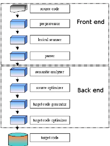
phases 2: front end, middle end and back end. The middle-end phase is not used anymore nowadays. A typical compiler architecture is shown in figure 5.1.
This chapter describes these phases and introduces a tool, JavaCC, used for the construction of some parts of the translator.
5.1
Front end
The front end takes an input and analyzes the source code to build an internal representation of the program, called the intermediate representation. It also manages the symbol table, if it is present, a data structure mapping each symbol in the source code to associated information such as location, type and scope.
This is done over several phases, which includes the following: 1. Line reconstruction
Languages which allow arbitrary spaces within identifiers require a phase before parsing, which converts the input character sequence to a
1see also section 1.4 for a detailed compiler and translator definition
2There are also one-pass compiler that have only one phase, but are not described here
42 CHAPTER 5. GENERAL COMPILER DESIGN
Figure 5.1: A typical compiler architecture
canonical form ready for the parser. This phase is not necessary in the present project, because nesC doesn’t allow such keywords.
2. Lexical analysis
This phase breaks the source code text into small pieces called tokens. Each token is a single atomic unit of the language, for instance a key-word, identifier or symbol name. The token syntax is typically a regular language, so a finite state automaton constructed from a regular ex-pression can be used to recognize it. This phase is also called lexing or scanning, and the software doing lexical analysis is called a lexical analyzer, lexer or scanner.
5.2. BACK END 43 Some languages, like C, require a preprocessing phase which supports macro substitution and conditional compilation. Typically, the prepro-cessing phase occurs before syntactic or semantic analysis.
4. Syntax analysis
This phase involves parsing the token sequence to identify the syntactic structure of the program. This phase typically builds a parse tree, which replaces the linear sequence of tokens with a tree structure built according to the rules of a formal grammar which define the language’s syntax. The parse tree is often analyzed, augmented, and transformed by later phases in the compiler.
5. Semantic analysis
During this phase the compiler adds semantic information to the parse tree and builds the symbol table. This phase performs semantic checks such as type checking (checking for type errors), or object binding (as-sociating variable and function references with their definitions), or definite assignment (requiring all local variables to be initialized before use), rejecting incorrect programs or issuing warnings. Semantic anal-ysis usually requires a complete parse tree, meaning that this phase logically follows the parsing phase, and logically precedes the code gen-eration phase, though it is often possible to fold multiple phases into one pass over the code in a compiler implementation.
5.2
Back end
The back end takes the intermediate representation and generates the final output of the translator or compiler. This is also done over several phases.
1. Analysis
This phase consists in the gathering of program information from the intermediate representation derived from the input. Typical analyses are data flow analysis to build use-define chains, dependence analysis, alias analysis, pointer analysis and escape analysis. Accurate analysis is the basis for any compiler optimization. The call graph and control flow graph are usually also built during the analysis phase.
44 CHAPTER 5. GENERAL COMPILER DESIGN The intermediate language representation is transformed into function-ally equivalent but faster or smaller3 forms. Popular optimizations are
inline expansion, dead code elimination, constant propagation, loop transformation, register allocation or even automatic parallelization. To speed up the development process this phase is not used in the present project and can maybe added in a later version of the transla-tor.
3. Code generation
The transformed intermediate language is translated into the output language.
5.3
JavaCC - a parser generator
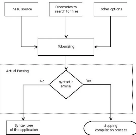
To realize the front end of the parser apart from the semantic analysis, the JavaCC ([JCCa]) parser generator has been used in the present project, which creates a top down parser (recursive descending)4.
In JavaCC the lexical specification in form of regular expressions and the grammar rules, called also grammar productions, are written down in the same file. Another important feature of JavaCC is the use of EBNF (Ex-tended Backus Naur Form), which enriches the BNF (Backus Naur Form) with regular expressions. JavaCC produces LL(1)5 parsers by default, but is
not limited to k=1 so k>1 is possible at any choice position. This functional-ity is achieved with syntactic and semantic lookahead6. A JavaCC-generated
parser can thus be LL(k) at the points where it is needed allowing so to parse all LL class of grammars.
Once all the grammar rules and lexical specification are written in a jj file, this file can be compiled by JavaCC and the Java classes that implement the compiler are generated as it can be seen in figure 5.2
5.4
JJtree - a parse tree generator
In the present project JJtree is used for building the parse tree in conjunction with the visitor design pattern. In this case the grammar written in a jjt file is used by JJtree to generate a jj file containing the grammar with generated
3in the sense that they need less memory
4see [ASU86] for the meanings of recursive descending and top down vs bottom up
parser
5see [ASU86] for more details
5.4. JJTREE - A PARSE TREE GENERATOR 45
Figure 5.2: File generation process of JavaCC
semantic actions for building the parse tree. In addition the visitor interface is generated allowing the separation of the structure and algorithm classes.
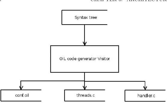
The implementation of the compiler resides only in the visitor classes. Therefore the semantic classes are compact and only contain the required visitor code and the compiler is not spread over dozens of semantic classes. Each semantic class is implemented by a Java class, which represents a node of the parse tree. Consequently, JJtree creates a class hierarchy which im-plements the Node interface. Part of the class hierarchy generated by JJtree for the present project can be seen in figure 5.3, where two classes, AST-Expression and ASTNesCFile, are represented. If a new node needs to be represented in the parse tree the corresponding Java class is automatically derived from SimpleNode.
Different types of concrete visitors can be implemented from the generated visitor interface, like for example a visitor responsible for the code generation. This is a flexible solution, because the actual semantics are done in separate visitor files, what gives a clear and scalable design.
JJTree generates semantic classes for all non terminals in a given gram-mar, which automatically get instantiated within the semantic actions. The following options written in the jjt file generate a parse tree in conjunction with the visitor pattern.
o p t i o n s {
MULTI = true ; VISITOR = true ; }
46 CHAPTER 5. GENERAL COMPILER DESIGN
Chapter 6
Architecture
6.1
Introduction
6.2
Software Requirements specification
6.2.1
Users of the software
In the following the type of users that are most likely going to use the software is listed.
1. Porter
Programmer that wants to port an existing TinyOS application to the Erika operating system.
2. Coder
Programmer that codes a nesC application for the Erika operating sys-tem from scratch.
3. Maintainer
Programmer that extends the nesC-Erika source code and fixes possible bugs.
4. Installer
User that installs the nesC-Erika software on a PC. 5. Tester
User that tests the correctness of the nesC-Erika software. 47
48 CHAPTER 6. ARCHITECTURE
6.2.2
Use cases
In this section a brief summary of the use cases is presented. 1. Porter
The Porter compiles an existing TinyOS application for Erika by sim-ply doing copy paste of the existing code. The porter should be able to do some manual changes on the generated files to optimize the ap-plication. He should get a final executable ready to be copied on the target platform.
2. Coder
The coder should be able to code a new application for the Erika op-erating system using the nesC language. He should obtain a final exe-cutable for his desired target platform ready to be copied on the target platform.
3. Maintainer
The maintainer needs documented source code to understand the code that has been previously written. It is advisable that the maintainer finds comments in the source code and that he writes comment in the new source code that it is been produced. The maintainer should be able to log software changes that he is going to do and to view previously changes done in the source code.
4. Installer
The installer should be able to install nesC-Erika on a PC by simply executing an installation script. Installation instructions and software requirements should be available for the installation.
5. Tester
NesC source codes samples, which tests some specific language con-structions should be available for a testing of new added nesC-Erika source code. In addition TinyOS demo applications should be avail-able to make final validation tests.
6.2. SOFTWARE REQUIREMENTS SPECIFICATION 49
6.2.3
Requirements definition
Based on the different use cases the following user requirements are defined. 1. Translation of a nesC-TinyOS application to a C application for Erika. 2. Extension of the nesC language to support Erika specific constructs. 3. Logging of software changes
4. Testing the correctness of existing and future source code.
6.2.4
System requirements specification
In this section functional and non functional system requirements are speci-fied. Functional system requirements are those requirements that the system has to offer to satisfy the needs of the different types of users. Non functional are those requirements that the system has to meet to work correctly. Functional system requirements specification
1. Translation of a nesC-TinyOS application to a C application for Erika. 1.1 The user should be able to specify the source files as command
line input.
1.2 A C file needs to be generated.
1.2.1 The C file must be compilable by the target compiler, which generates the final executable.
1.3 An OIL file needs to be generated.
1.3.1 The OIL file must be compilable by RT-Druid, an Erika spe-cific tool.
1.4 The output files should be generated in a human readable way to permit manual manipulation.
1.5 Any programming error should be reported in a human readable way.
1.5.1 The line number of the error should be signaled 1.5.2 The column number of the error should be signaled.
2. Extension of the nesC language to support Erika specific constructs. 2.1 A nesC API for Erika should be offered to permit coding of Erika