Network Address Translation
(NAT)
The process of Network Address Translation (NAT, also known as network masquerading) is the re-writing of the source and/or destination addresses of IP packets as they pass through a router or firewall.
NAT first became popular as a way to deal with the IPv4 address shortage and to avoid all the difficulty of reserving IP addresses. It has become a standard feature in routers for home and small-office Internet connections, where the price of extra IP addresses would often outweigh the benefits.
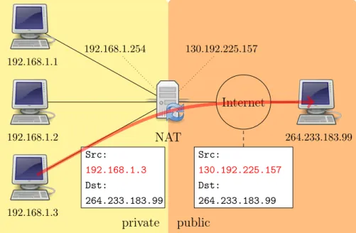
Another employment of NAT is NAT – Protocol Translation (NAT-PT, RFC 2766[86]), which allows IPv6-only hosts and applications to commu-nicate with IPv4-only ones, residing at the boundary between an IPv6 and IPv4 network and making packet conversion from one protocol to the other. The most common configuration of NAT should be more properly called Port Address Translation (PAT ), and allows a single IP address to be used for many internal hosts. In such configuration 4.1, a local network uses one of the designated “private” IP address subnets1, and a router on that network has a private address in that address space. The router is also connected to the Internet with a single public address. As traffic passes from the local network to the Internet, the source address in each packet is translated on the
fly from the private addresses to the public address. The router tracks basic data about each active connection (particularly the destination address and port). When a reply returns to the router, it uses the connection tracking data it stored during the outbound phase to determine where on the internal network to forward the reply; the TCP or UDP client port numbers are used to demultiplex the packets in the case of PAT, or IP address and port number when multiple public addresses are available, on packet return. To a system on the Internet, the router itself appears to be the source/destination for this traffic. private public Internet 130.192.225.157 192.168.1.254 Src: 192.168.1.3 Dst: 264.233.183.99 Src: 130.192.225.157 Dst: 264.233.183.99 NAT 192.168.1.1 192.168.1.2 192.168.1.3 264.233.183.99
Figure 4.1: Typical network configuration of NAT
Hosts behind a NAT-enabled router do not have true end-to-end con-nectivity and cannot participate in some Internet protocols. Services that require the initiation of TCP connections from the outside network, or state-less protocols such as those using UDP, can be disrupted.
In addition to the convenience and low cost of NAT, the lack of full bidirectional connectivity can be regarded in some situations as a feature rather than a limitation. To the extent that NAT depends on a machine on the local network to initiate any connection to hosts on the other side of the
router, it prevents malicious activity initiated by outside hosts from reaching those local hosts.
It has been argued that the wide adoption of IPv6 would make NAT useless, as it is a method of handling the shortage of IPv4 address space. However, this argument either ignores the natural firewall provided by NAT. Some higher-layer protocols (such as FTP and SIP) send network layer address information inside application payloads. However, those addressed may be invalidated by the NAT changing the addresses in the IP header.
There are a few ways that are being used to circumvent this problem:
• Application Level Gateways (ALG): software module running on a NAT firewall device which updates any payload data made invalid by address translation. ALGs obviously need to understand the higher-layer pro-tocol that they need to fix, and so each propro-tocol with this problem requires a separate ALG;
• NAT cooperation: there are some protocols like Universal Plug and Play (UPnP, [87]) or Bonjour (NAT-PMP, [22]) which require cooperation of the NAT device with the applications; these protocols will not be considered in this work;
• application only techniques: the high level protocol must be designed with NAT traversal in mind; the application uses methods like UNi-lateral Self-Address Fixing (UNSAF, RFC 3424[26]), STUN 4.4 and ICE 4.6; this methodology does not make any assumption on the NAT device, however it does not work reliably across poorly-behaved legacy NATs; these techniques will be considered in this work, as it is the only one that allows to put the intelligence for NAT traversal only in the application without modification of intermediate nodes;
• relaying: in this case a public node is acting as a forwarder of the traffic from one node to the other; this is a fall-back case, when other techniques have failed.
4.1
NAT Behavior
Unfortunately, TCP/IP was not designed for the presence of NAT device. They were introduced recently by different router producers separately. For this reason, there is no specification on NAT behavior, and NAT from differ-ent vendors are differdiffer-ent one form each other in the way they handle network packets.
During to the troubles that were causing to Internet applications, in par-ticular to SIP, the IETF BEHAVE Working Group wrote RFC 4787[1] that analyzed NAT behavior and defined some requirements a “well-behaved” NAT should respect.
In tis section we will classify the NAT behaviors are are interested for this work, following the terminology of RFC 4787.
4.1.1
Mapping
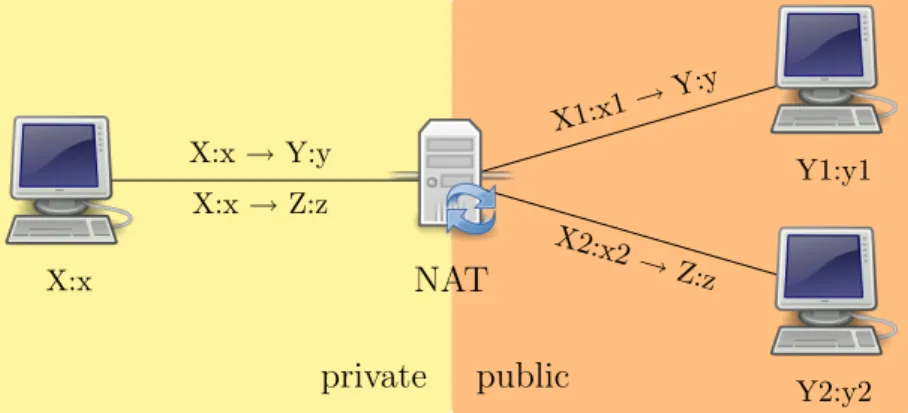
When an internal endpoint opens an outgoing session through a NAT, the NAT assigns the session an external IP address and port number so that sub-sequent response packets from the external endpoint can be received by the NAT, translated, and forwarded to the internal endpoint. This is a mapping between an internal IP address and port IP:port and external IP:port tuple. It is important to distinguish the behavior of the NAT when there are multiple simultaneous sessions established to different external endpoints (see figure 4.2).
The NAT mapping can be:
• Endpoint-Independent Mapping: The NAT reuses the port mapping for subsequent packets sent from the same internal IP address and port (X:x) to any external IP address and port. Specifically, X1’:x1’ equals X2’:x2’ for all values of Y2:y2.
• Address-Dependent Mapping: The NAT reuses the port mapping for subsequent packets sent from the same internal IP address and port (X:x) to the same external IP address, regardless of the external port. Specifically, X1’:x1’ equals X2’:x2’ if and only if, Y2 equals Y1.
private public X:x → Y:y X:x → Z:z X1:x1→ Y:y X2:x2 → Z:z X:x Y1:y1 Y2:y2 NAT
Figure 4.2: NAT address and port mapping
• Address and Port-Dependent Mapping: The NAT reuses the port map-ping for subsequent packets sent from the same internal IP address and port (X:x) to the same external IP address and port while the map-ping is still active. Specifically, X1’:x1’ equals X2’:x2’ if and only if, Y2:y2 equals Y1:y1.
It is important for the mapping to be endpoint-independent, otherwise NAT traversal possibilities would be severely limited, as will be showed later.
4.1.2
Filtering
When an internal endpoint opens an outgoing session through a NAT, the NAT assigns a filtering rule for the mapping between an internal IP:port (X:x ) and external IP:port (Z:z ) tuple. The filtering behavior can be classi-fied in these three categories:
• Endpoint-Independent Filtering: The NAT forwards any packets des-tined to X:x, regardless of the external IP address and port source (Y:y). In other words, sending packets from the internal side of the NAT to any external IP address is sufficient to allow any packets back to the internal endpoint (figure 4.3).
• Address-Dependent Filtering: The NAT will filter out packets from Z:z destined for the internal endpoint X:x if X:x has not sent packets to
private public X:x Y:y Z:z NAT X’:x’ 1 2
Figure 4.3: NAT endpoint-independent filtering
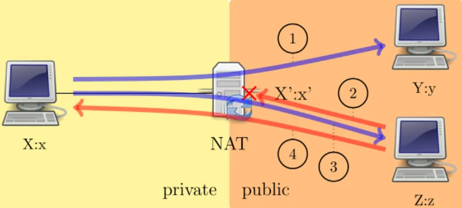
Z:any previously (independently of the port used by Z). In other words, for receiving packets from a specific external endpoint, it is necessary for the internal endpoint to send packets first to that specific external endpoint’s IP address 4.4. private public X:x Y:y Z:z NAT X’:x’ 1 2 3 4
Figure 4.4: NAT address-dependent filtering
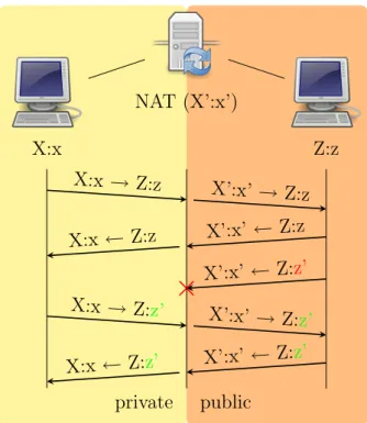
• Address and Port-Dependent Filtering: This is similar to the previous behavior, except that the external port is also relevant. The NAT will filter out packets from Z:z destined for the internal endpoint X:x if X:x has not sent packets to Z:z previously. In other words, for receiving packets from a specific external endpoint, it is necessary for the internal endpoint to send packets first to that external endpoint’s IP address and port 4.5.
private public X:x NAT (X’:x’) Z:z X:x → Z:z X’:x’ → Z:z X’:x’ ← Z:z X:x ← Z:z X’:x’ ← Z:z’ X:x → Z:z’ X’:x’ → Z: z’ X’:x’ ← Z:z’ X:x ← Z:z’
Figure 4.5: NAT address and port dependent filtering
The endpoint-independent filtering is clearly the most favorable to NAT traversal. However, it is possible that network administrators prefer having a NAT with filtering policies for security reasons. In this case, it is impor-tant (and also recommended by RFC 4787[1]) that NAT have only address dependent filtering and not port and address dependent, because the last one would make NAT traversal more difficult.
4.1.3
Hairpinning support
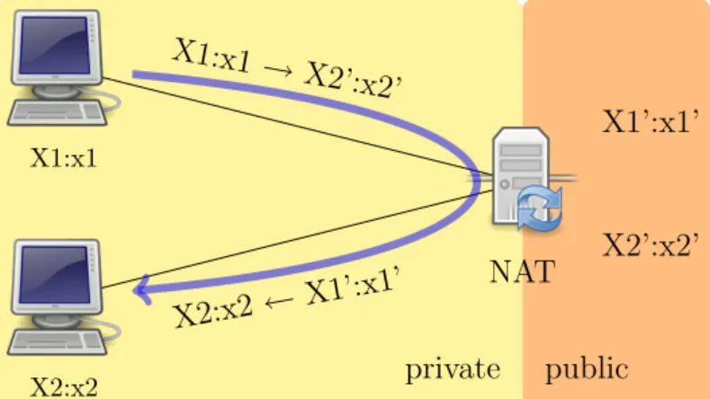
Let X1 and X2 be two hosts behind the same NAT, and let X10 : x10 and X20 : x20 respectively their mapped addressed on the NAT public side. It X1 sends traffic to X20 : x20, it arrives to the NAT. If the NAT forwards this traffic to X2 : x2, it is said to be doing hairpinning (see figure 4.6).
Hairpinning allows two endpoints on the internal side of the NAT to communicate even if they only use each other’s external IP addresses and ports.
private public X1:x1 X2:x2 NAT X1’:x1’ X2’:x2’ X1:x1 → X2’:x2’ X2:x2 ← X1’:x 1’
Figure 4.6: NAT external hairpinning
Note that typically X10 is the same as X20, i.e. the NAT has only one public IP address.
Furthermore, the NAT may present the hairpinned packet with either an internal (X1 : x1) or an external (X10 : x10) source IP address and port. Therefore, the hairpinning NAT behavior can be either External source IP address and port or Internal source IP address and port (like in figure 4.6. The first one may cause problems by confusing implementations that expect an external IP address and port.
4.1.4
Other NAT behaviors
Many NAT include an ALG, which may modify the data that in traversing it. However this operation are out of the control of the application and may interfere with normal operations.
Moreover, it has to be noted that NAT behavior is not always the same, but it can change in an unpredictable way. For example, some NATs have been reported to have endpoint independent filtering only if it can preserve the port number associated with the private IP when mapping it to a public address. In other words, if X : x is a masqueraded host, sends a packet to a public IP address, the NAT will behave with:
• address-dependent filtering if it port X0 : x is already occupied.
For this reason, RFC 4787 discourage discovering the NAT behavior, as it can be different from one connection to the other opened by the same application.
4.1.5
Legacy NAT classification
Other than the classification of NAT behavior reported in the previous sec-tion, there is another division of NAT typed in four classes, introduced by the first STUN RFC (3489[73]):
• Full cone: all requests from the same internal IP address and port are mapped to the same external IP address and port. In this case any external host can send a packet to the internal host, by sending a packet to the mapped external address.
• Restricted cone: it is like a full cone but an external host, with IP address X, can send a packet to the internal one only if the internal host had previously sent a packet to the IP address X.
• Port restricted cone: it is like a restricted cone but the restriction includes port numbers. Therefore an external host can send a packet, with source IP address X on port x, to the internal host only if the internal host had previously sent a packet to IP address X and port x. • Symmetric: all requests from the same internal IP address and port, to a specific destination IP address and port, are mapped to the same external IP address and port. If the same host sends a packet with the same source address and port, but to a different destination, a different mapping is used.
This second classification, does not capture all the possible behaviors considered by BEHAVE specifications, anyway it is simpler and suitable for out purposes. For this reason it will be used in the rest of this work.
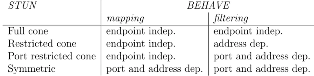
Table 4.1 shows the correspondence between STUN classification and BEHAVE classification.
STUN BEHAVE
mapping filtering
Full cone endpoint indep. endpoint indep.
Restricted cone endpoint indep. address dep.
Port restricted cone endpoint indep. port and address dep. Symmetric port and address dep. port and address dep.
Table 4.1: Mapping between STUN and BEHAVE classification
4.2
NAT Traversal
In this section NAT traversal techniques [80] will be examined, which can be performed at the application level by the endpoints involved in the commu-nication.
All these techniques involve the UNilateral Self-Address Fixing (UNSAF, RFC 3424[26]) method. UNSAF are processes whereby some originating endpoint attempts to determine or fix the address (and port) by which it is known to another endpoint — e.g. to be able to use address data in the protocol exchange, or to advertise a public address from which it will receive connections.
We will present possible scenarios for NAT traversal under the following assumptions:
1. client A needs to open a connection with client B; it has address Y : y;
2. client B is behind a NAT and has private address X : x;
3. both client A and B are connected with a rendez-vous server S, which has public address Z : z, with which they run some kind of protocol.
4.2.1
Relaying
Relaying is the method which is most likely to work, even thought it is the most expensive. In fact A sends all the packets for B to S, which, in turn, forwards them to B (see figure 4.7).
This method has the advantage that it will always work, independently of the address realm of A (public or private) as long as both clients have
public private Client B X:x Client A Y:y Rendez-vous Z:z NAT Figure 4.7: Relaying
connectivity to the server and with any kind of NAT along the path.
The obvious disadvantages of relaying are that it consumes the server’s processing power and network bandwidth, and communication latency be-tween the peering clients is likely to be increased even if the server is well-connected.
4.2.2
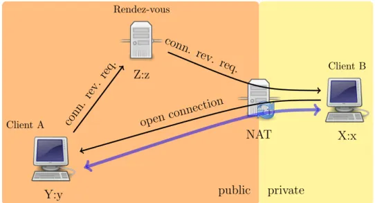
Connection reversal
This techniques is applicable only if client A has a public address. When A wants to open a connection to B, it asks the rendez-vous server to deliver a reverse connection request to B, which, in turn, open the actual data connection towards A (see figure 4.8).
4.2.3
UDP hole punching
UDP hole punching in a procedure that allows two endpoints to establish direct connectivity with each other, even when both communicating hosts lie behind NAT devices. It “punches holes” in the NAT or firewall with the help of a rendez-vous server, but, after the connection has been established, that server is no longer needed (figure 4.9).
public private Client B X:x Client A Y:y Rendez-vous Z:z NAT conn. rev. req. conn. rev. req. open connection
Figure 4.8: Connection reversal
Traditional UDP hole punching requires both NAT not to be symmetric (i.e. to have an endpoint-independent mapping), but poses no requirements on the filtering, which can also be port and address dependent. Anyway, in paragraph 4.2.4 a mechanism for doing UDP hole punching between a Symmetric NAT and a Full or Restricted Cone NAT will be described.
This technique has been used primarily with UDP applications, but not as reliably with TCP applications. See paragraph 4.2.5 for a description of TCP hole punching.
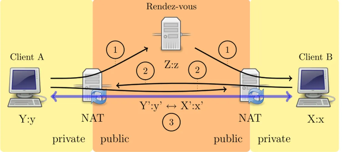
Client behind two different NATs
If client A wanted to establish a UDP session with client B and sent UDP packets to B’s mapped address (X0 : x0), they would be dropped by NAT A (unless it were a Full Cone).
Therefore client A could ask the rendez-vous server to send a message (number 1 in figure 4.9) to client B and tell him to send UDP packets (n. 2) to client A’s mapped address (Y0 : y0). This messages would enable NAT B to accept packets from A’s mapped address destined to client A. At the same time, client A would start sending UDP packets (n. 3) to B’s public address (X0 : x0), enabling NAT A to accept packets from X0 : x0 for client A.
public private private public Client B X:x Client A Y:y Rendez-vous Z:z NAT NAT Y’:y’ ↔ X’:x’ 1 1 2 2 3
Figure 4.9: UDP hole punching
At this point client A and B can communicate with a direct session using their mapped public addresses, i.e. Y0 : y0 and X0 : x0 respectively. The help of the rendez-vous server is then no longer needed.
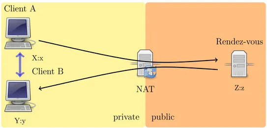
Client behind the same NAT
If client A and B are both behind the same NAT (figure 4.10), the UDP hole punching mechanism will work the same way, provided that the NAT supports hairpinning. In fact, they will be addressing each other using their public mapped addresses, both belonging to the same NAT.
Even if hairpin translation is supported by the NAT, the translation and forwarding step is obviously unnecessary in this situation, and is likely to add latency to the dialog between A and B as well as burdening the NAT.
The solution to this problem is to have A and B communicating with each other using their private addresses 4.11. When they learn the counterpart address through the rendez-vous server, they also advertise their private IP address. Before starting the UDP hole punching procedures, they try send some UDP packets using those private addresses to check if they can reach each other without passing through the NAT. It is important that these packets be authenticated in some way, however, since in the case of different NATs it is possible for A’s messages directed at B’s private address to reach
private public X:x Client A Y:y Client B NAT Z:z Rendez-vous X:x → Y’:y’ Y:y ← X’:x’
Figure 4.10: UDP hole punching when clients are behind the same NAT
some other, unrelated node on A’s private network, or vice versa.
private public X:x Client A Y:y Client B NAT Z:z Rendez-vous
Figure 4.11: Direct connection when clients are behind the same NAT
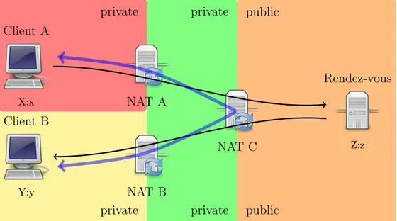
Client behind multiple levels of NAT
There are some network configurations where optimal connectivity cannot be obtained and, moreover, hairpinning support is required in order to achieve a direct connection. For example, like in figure 4.12, client A and B are behind two levels of NAT, and share the topmost NAT device (NAT C).
private public private public private private X:x Client A Y:y Client B NAT A NAT B NAT C Z:z Rendez-vous
Figure 4.12: UDP hole punching when clients are behind multiple levels of NAT
In this case, neither client A, client B nor the rendez-vous server have knowledge of the intermediate private LAN, so they can not discover the addresses mapped on NAT A and B. Moreover local addresses of client A and B do not work, because they are in different subnet. Therefore the best connection that can actually be achieved is through hairpinning on NAT C. If it does not support hairpinning, fall-back to relaying must be used.
4.2.4
UDP hole punching with Symmetric NAT
As anticipated, it is also possible to extend the traditional UDP hole punching to the case in which one endpoint is behind Symmetric NAT and the other is behind a Full or Restricted Cone.
Suppose that Client B is behind a Symmetric NAT (NAT B). The pro-cedure start as the standard one. The endpoints get to know the correspon-dent mapped address through the rendez-vous server and start sending UDP packets to those addresses. The difference comes in the fact that NAT B will change client B’s mapped address for packets destined to A. For the procedure to succeed, NAT A must accept these packets from NAT B,
ei-ther because it is a Full Cone or because it is an Address Restricted but has already send some messages to the public IP of NAT B (e.g. when trying to contact Client B using its mapped address learned from the rendez-vous server). Then, from those packets, client A will learn client B’s new public mapped address.
4.2.5
TCP hole punching
Hole punching is also possible with TCP, even though it is more complicated and less likely too succeed (around 60% of success rate, according to [28]). This technique is briefly described here for sake of completeness, but will not be considered in the rest of this work.
Most TCP sessions start with one endpoint sending a SYN packet, to which the other party responds with a SYN-ACK packet. It is permissible, however, for two endpoints to start a TCP session by simultaneously sending each other SYN packets, to which each party subsequently responds with a separate ACK. This procedure is known as Simultaneous TCP Open tech-nique and may be found in the original TCP specification [57]). However, Simultaneous TCP Open is not implemented correctly on many systems, including NAT devices.
TCP hole punching exploit this TCP feature: both clients start sending TCP SYN packets at the same time to the public mapped address of the other host. When a NAT receives such a SYN packet, will normally drop or reject it with a RST packet. However, it if it has just send a packet with the same addresses but on the opposite direction, it will consider the connection active and accept it.
4.2.6
NAT keep-alive
When an outgoing packet traverses a NAT device creating a new outgoing session, the NAT generates some rules in order to allow packets in the oppo-site direction to reach the masqueraded node.
As UDP is connectionless, these rules are automatically deleted after some time of inactivity along that connection. They are also deleted in case
of TCP because it is possible that node disconnect from the network without properly closing the TCP connection.
For this reason it is necessary that the NAT binding is periodically re-freshed, is packets are sent along the connection. In case of UDP, the ap-plication must take care of sending so called keep-alive messages. In case of TCP, the protocol itself provides a keep-alive function; the application must only make sure it is enabled.
Moreover, it has to be noted that some NAT refresh the binding only for outgoing packets, in order to prevent an external node to keep sending messages and keep the binding open against the will of the private node.
4.3
NAT Traversal with SIP
SIP is the protocol from IETF which has been suffering most troubles because of NAT. SIP procedures has been extended ad different levels in order to improve functionality in case of connections through NAT.
4.3.1
Symmetric Response Routing
The SIP protocol can be used over connectionless sessions like UDP. In this case UASs send responses to the address and port specified in the Via header, which was recorded in the request message (see 2.6).
However, if the request traversed a NAT before reaching the current node, the port recorded in the Via header does not match the source port of the UDP packet, which has been rewritten by the NAT. Only the NAT IP address would have been recorded in the received parameter of the Via header.
For this reason the response would be sent to the wrong port of the NAT device and thus dropped.
In order to overcome this limitation, Symmetric Response Routing was described in RFC 3581[71], which defines a new parameter of the Via header, called rport.
The rport parameter is similar to the received one but the rport con-tains a port number while the received concon-tains an IP address. Note that
rport parameter has to be generated with no value by the client because it is used to indicate to the sever that this extension is supported and requested for that transaction.
When a server (UAS or proxy) compliant with this specification receives a request, it examines the topmost Via header and, if it finds a blank rport parameter, it must fill up the parameter with the source port of the request message.
Vice versa, when it must forward a response, if it finds an rport value in the topmost Via header of the message, it sends the response to that port, instead of to the port specified in the legacy part of the header.
The purpose of this procedure allows a masqueraded client to correctly receive responses to requests. However it can also be used by the UA to be able to receive new requests. In fact, a UA behind a NAT can:
1. send the initial REGISTER specifying the rport parameter;
2. learn its mapped address from the received and rport parameters and issue a new REGISTER, specifying the new address in the Contact header;
3. periodically send a message (like an OPTION request to the SIP server in order to keep the NAT binding alive.
This techniques, however has some drawbacks:
• the masqueraded UA can receive requests only from the server to which it sent the REGISTER message (unless it is behind a Full Cone NAT), thus the registrar must be co-located with the proxy server (or, more generally, messages for the registrar must pass through the proxy);
• the usage of OPTIONS messages for NAT keep-alive require some net-work overhead and processing in endpoints, which is not strictly nec-essary just for NAT keep-alive; this method is deprecated by the SIP community, however it is actually used by some SIP VoIP providers.
4.3.2
SIP Outbound
The latest solution proposed by IETF to the limitation introduced by the deployment of NATs and firewalls is provided by SIP Outbound [42].
When a UA sends a REGISTER request using this specification it creates a flow (i.e. a bidirectional stream of datagram over UDP or a TCP channel) towards the outbound proxy, which can reuse this flows later for forwarding requests to that UA.
Flows are identified by two new parameter of the Contact header: the req-id and the instance-id. The former represents a registration ID (unique for simultaneous registrations) and the latter is a URN (Uniform Resource Name) that uniquely identifies that instance of a UA.
An additional draft [65] specify procedures for outbound proxies discovery and procedure for recovery in case of failure of the outbound proxy during mid-dialog transactions.
However these procedures are still under specification and untested and tends to be quite complicated. Moreover SIP Outbound requires the out-bound proxy to put a Record-Route header in all dialog-creating requests, thus definitely excluding the possibility to create direct connections between peers.
4.4
STUN
STUN (Session Traversal Utilities for NAT, [67]) is a lightweight request/re-sponse protocol that provides a wide set of functions to deal with NATs, allowing to an application:
• learn the addresses and port allocated by the NAT; • maintain open the NAT bindings (binding keep-alive);
• perform a connectivity check with other STUN-aware entities.
STUN works with many existing NATs, and does not require any special behavior from them. Its functions should help overcoming many of the lim-itations introduced by NATs like the block of the majority of the existing
IP applications such as P2P, multimedia and game programs. Besides these functionalities provide a solution for poor scalability and reliability caused by the use of ALGs (Application Layer Gateway).
STUN was firstly specified in RFC 3489[73] under the name of Simple Traversal of UDP through NAT. This first version worked only with UDP and was also specialized in NAT type detection. However, NAT detection was later deprecated and STUN was modified up to the last specification in draft [67].
Typically the STUN client is embedded in an application which needs to obtain a public IP address a port that can be used to receive data. With the new specification of STUN, STUN packets are multiplexed on the same port of SIP, RTP or RTCP (ora any other protocol that needs it) and application include a STUN server too.
4.4.1
STUN messages
STUN messages divides into methods and classes. The method specifies the scope of the operation:
1. Binding: used by the client to discover the mapped address;
2. Shared Secret : used exchange a shared secret used to ensure integrity of binding messages.
Classes specify the type of message:
1. Request : sent from client to server;
2. Indication: can flow from client to server and vice versa; currently no indication messages are defined in STUN specification;
3. Success Response: sent from server to client;
Binding Request and Response
The STUN client creates a STUN Binding Request to discover the presence of a NAT and to learn the public IP address and port mappings assigned by the NAT. STUN Binding Requests can pass through one or more NATs before reaching the STUN server, the source IP address and port elaborated by the server are referred to the NAT closest to it.
When the STUN server receives a Binding Request it copies that source IP address and port of this request into a STUN Binding Response (in the MAPPED-ADDRESS or XOR-MAPPED-ADDRESS field) and sends it back to the source IP address and port of the STUN request. In this way the client can compare the IP address and port contained in the payload of the binding response (defined as its Reflexive Transport Address) with its local IP address and port (i.e. its Transport Address). If they do not match the client knows that it is behind one or more NATs.
If the STUN server is publicly routable the IP address and port in the STUN Binding Response messages are also publicly routable, therefore they can be used by any host on the public Internet to send packets to the appli-cation that sent the STUN request, provided that the NAT is a Full Cone NAT. In this way an application only needs to listen on the IP address and port from which the STUN request was sent.
Shared Secret Request and Response
There are several attacks possible on STUN systems but many of them can be prevented through message integrity. A shared secret exchanged between client and server is used as keying material for an HMAC2, providing the
required message integrity for Binding Requests and Responses. The shared secret exchange is realized via Shared Secret Requests and Shared Secret Responses. It is fundamental that the used shared secrets has at least 128 bit of randomness.
2Keyed-Hash Message Authentication Code: it is a type of message authentication code
calculated using a cryptographic hash function (e.g. MD5, SHA-1) in combination with a key. HMAC is used to verify the data integrity and the authenticity of a message
4.4.2
Message structure
STUN messages are TLV (type-length-value) encoded using big endian (net-work ordered) binary. All STUN messages start with a STUN header (figure 4.13, followed by a STUN payload. The payload is a series of STUN at-tributes (figure 4.14), the set of which depends on the message type.
00 Message Type Message Length
Magic Cookie (32 bits)
Transaction ID (96 bits)
Figure 4.13: STUN Message Header Structure
Type Length
Value
Figure 4.14: STUN Message Attribute Structure
The STUN header contains:
1. the type of the message (i.e. message class and method);
2. the length in bytes of the payload excluding the header;
3. the magic cookie which is always 0x2112A442 and is used to recog-nize STUN packages when multiplexed on the same port with another protocol;
4. the transaction ID used to correlate requests with relative responses;
Here follows a list of the most significant attributes:
• XOR-MAPPED-ADDRESS: it is present in Binding Responses and contains the mapped transport address, as seen be the STUN server; the address is obfuscated through the XOR function with the magic cookie, in order to prevent ALG to recognize and rewrite it;
• ERROR-CODE: it must be present in Error Binding Responses and it contains en error code consistent with SIP error code numbering (table 2.2, and a human-readable reason phrase;
• ALTERNATE-SERVER: it is present in Error Binding Responses of error code 300, and it used to redirect the client to another STUN server; • FINGERPRINT: it is a CRC value for the STUN message, used in
partic-ular when STUN is multiplexed with another protocol;
• REFRESH-INTERVAL: it is put in a Binding Response by a STUN server in order to suggest the client a refresh interval for the NAT binding.
• USERNAME, PASSWORD, MESSAGE-INTEGRITY, REALM, NONCE: are used to ensure message autentication and integrity; they will not be discussed here.
• RESPONSE-ADDRESS, CHANGED-ADDRESS, CHANGE-REQUEST, SOURCE-AD-DRESS, REFLECTED-FROM: were used to perform NAT type discovery and have been removed from the current specification of STUN.
4.4.3
STUN and SIP
Applications like SIP require that clients include IP address and port infor-mation in several places such as the Contact header field, the SDP (section 2.10.1) body etc. In order to make SIP application traverse NATs using STUN, when an UA is going to send a protocol message, it has to find out all the places in the PDU (Protocol Data Unit) where it is supposed to in-sert its IP address and port. Besides it has to allocate a port from the local interface and, from that port, start the STUN procedures.
Furthermore when an UA wants to establish a media session, it needs to open more connection (for each media flow, at least one RTP and possibly one RTCP). This means that the UA has to send three STUN binding request, one for each connection.
4.4.4
Limitations of STUN
Just having SIP to discover its mapped address and placing it inside outgoing messages is not enough for effective NAT traversal, but works only in case of Full Cone NATs. For example, if a UA behind Restricted NAT receives an INVITE request and answers placing its mapped address in the Contact header, the inviting UA will try to send the ACK directly, but that packet will be filtered by the NAT of the invited UA.
Moreover NAT discovery techniques can not give accurate results because of the may unpredictable behaviors of such network elements.
Therefore, NAT discovery procedures have been dropped and STUN has become a tool for connectivity maintenance for other more advanced proce-dures like SIP Outbound (section 4.3.2) and ICE (4.6).
4.5
STUN Relay Usage
For those situations when the only way to obtain a useful transport address is to use a relay, IETF has defined a new mechanism and new messages that let the STUN server act as a packet relay. These procedures fall under the name of STUN Relay Usage [68], formerly known as Traversal Using Relay NAT (TURN ).
The STUN relay is situated on the public Internet and provides transport addresses to the NATted clients.
A STUN relay store association with relay client as internal 5-tuples and permissions for remote hosts in external 5-tuples, as depicted in figure 4.15. A 5-tuples is a combination of the source IP address and port, destination IP address and port, and transport protocol (UDP, TCP, or TLS over TCP). It uniquely identifies a TCP connection, TLS channel, or bi-directional flow of UDP datagrams.
4.5.1
Messages
private public STUN Relay Client External Client NAT STUN Relay Server internal remote transport address internal local transport address external local transport address external remote transport address internal 5-tuple external 5-tuple
Figure 4.15: STUN Relay Usage network layout
1. Allocate request/response: to request the allocation of relayed addrres;
2. Send Indication: used by the client to ask the STUN server to send data to a remote address;
3. Data Indication: used by the STUN server to forward to the client the data received from a remote host;
4. Set Active Destination request/response: used by the client to spec-ify a remote address that will be used for forwarding traffic without Send/Data Indication encapsulation;
5. Connect request/response: used by the client to ask the STUN Relay to open a TCP connection to a remote address.
6. Connect Status Indication: used by the STUN server to report to the client the status of the TCP connection on its public side.
The new attributes types are:
• BANDWIDTH: if known, it defines the maximum bandwidth that will be used for the binding;
• REMOTE-ADDRESS: it specifies the address and port of the peer as seen from the STUN relay server;
• DATA: it is present only in Send/Data Indications and contain the raw data of the encapsulated packet;
• RELAY-ADDRESS: it is present in Allocate Responses and specifies the address and port that the server allocated to the client;
• REQUEST-PORT-PROPS: it is used to request specific port properties (such as odd/even port alignment);
• REQUEST-TRANSPORT: it is used to obtain a specific transport protocol for the allocated transport address;
• REQUEST-IP: it is used by the client to obtain a specific IP address (useful in case of multi-homed STUN Relay servers).
4.5.2
Allocate Requests
Initial requestWhen the relay client needs to obtain a transport address it sends an Allo-cate Request towards the relay server including its credentials (that can be acquired by a Shared Secret Request/Response exchange).
Relay server identifies an initial request when its source and destination transport addresses do not match the internal remote and local transport addresses of an existing internal 5-tuple.
Allocate Requests only reserve transport addresses on the relay server: no data flows through these allocated port until the relay client sends a Send Indication to the relay server.
If any of the requested constraints cannot be met by the relay server then it can reject the Allocate Request or it can be redirect the relay client towards another server which maybe can fulfill the request.
Subsequent requests
If the relay client wants to maintain the obtained allocation it needs to refresh the allocation sending another Allocate Request before 3/4 of the allocation lifetime has passed. The new Allocate Request must include the shared secret used in the previous request or a short-term password derived from it. In a successful response the RELAY-ADDRESS attribute contains the same transport address previously obtained, while the LIFETIME attribute contains the additional time the binding will live without being refreshed.
Note that if a relay client no longer needs the binding it should tear it down sending a new Allocate Request with the LIFETIME attribute set to zero.
Relay servers identify a subsequent request when source and destina-tion transport addresses matches the internal remote and local transport addresses of an existing internal 5-tuple.
4.5.3
Send/Data Indication
Send IndicationAfter the allocation process, Send Indication message is used by the relay client in order to create permissions on the server and send data to an external client.
When the relay server receives a Send Indication message, it verifies that the message arrived with source and destination transport addresses equal to the internal remote and local transport addresses of an internal 5-tuple associated with an existing allocation. After this check the server creates a IP packet (UDP or TCP regarding the type of the required allocation) setting:
• the packet payload equal to the content of the DATA attribute;
• the source IP address equal to the allocated transport address;
If the client required a UDP allocation then the relay server can send this packet, otherwise it checks if it has an existing TCP connection open from the allocated transport address to the address defined in the REMOTE-ADDRESS attribute. If not, the server discard the data.
In caso of TCP transport, before sending data, a relay client has to wait for the peer to create a TCP connection with the STUN relay server for every TCP allocated transport addresses. Otherwise all the data sent with Send requests will be silently discarded by the relay server.
When the packet is sent to the external client, the relay server adds the IP address specified in the REMOTE-ADDRESS attribute to the permission list for this allocation.
Data Indication
After the creation of the requested binding, the relay server can begin to relay packets from the external clients towards the relay client. When a STUN Relay server receives a packet on the transport address associated to a client, it can take one of the following three actions:
1. forward the packet to the relay client, if the source address is the active destination (see sect section);
2. encapsulate the packet in a Data Indication message and send it to the relay client, if the source address is not the active destination but the relay server has already received a Send Indication with that address in the REMOTE-ADDRESS attribute;
3. discard the packet otherwise.
4.6
ICE
Interactive Connectivity Establishment (ICE, [66]) is a methodology that tries to provide a unique flexible solution for media streams established by signaling protocols based on the offer-answer model (e.g. SIP), using the
STUN protocol and and STUN Relay. Besides, ICE deprecates ANAT (sec-tion 2.10.3).
Nowadays clients are spread over so many networks with different ad-dressing realms such as private and public networks but also IPv4 and IPv6 networks, and VPNs. In this kind of scenario clients cannot know a priori which realms they share with other peers and therefore it is necessary to try connecting to addresses in all realms in order to communicate in a properly way.
This protocol seeks to create a media flow directly between participants, so that there is no application layer intermediary between them. This is done to reduce media latency, decrease packet loss, and reduce the operational costs of deploying the application. However, this is difficult to accomplish through NAT, because there many network configurations and assumptions should not be made about the topologies of the networks in which their solutions will be deployed. This protocol wants to propose a single solution which is flexible enough to work well in all situations.
ICE is an extension to the offer/answer model, and works by including a multiplicity of IP addresses and ports in SDP offers and answers, which are then tested for connectivity by peer-to-peer STUN exchanges. The IP ad-dresses and ports included in the SDP are gathered using the STUN binding acquisition techniques (see section 4.4.1) and relay allocation procedures (see section 4.5.2).
4.6.1
Transport Addresses
An client can have many transport addresses (pairs of IP address and port) referring to itself. ICE calls candidates all the transport addresses that are suitable to be included in an offer and validated. They are divided into four main categories:
• Host Transport address: it is an address assigned to an interface of the host; note that this interface can be physical (like an Ethernet card) or virtual (like a VPN interface);
• Server Reflexive Transport address: it is discovered via a Binding re-quest to a STUN server distinct from the peer;
• Peer Reflexive Transport address: it is discovered via a Binding request to the STUN server running in the peer;
• Relayed Transport address: it is obtained via an Allocate Request to a STUN Relay server.
4.6.2
Creating the offer
Before starting a new session, the offerer acquires host transport addresses for media streams from its IPv4, IPv6, or VPN network interfaces. After that, it obtains server reflexive and relayed transport addresses through a single STUN Allocate Request. Note that all these requests are processed at a fixed rate in order to avoid NAT overload
The host, server reflexive and relayed transport addresses are formed into candidates, each of which represents a possible set of transport addresses that might be viable for a media stream.
In the example in figure 4.16 the client is placed behind a NAT and its offer contains a host candidate and a server reflexive one. These candidates need to be prioritized, therefore the host candidate receives the highest priority (i.e. 1.0), while the server reflexive candidate is associated with a lower priority (i.e. 0.7). Besides the client chooses its reflexive server address as operative candidate and includes it into the m/c lines.
4.6.3
Creating the answer
The answer is generated in a similar way: the answerer acquires addresses all its available transport addresses from those (messages 6-7), and then groups them into candidates in order to include them in a=candidate attributes in the answer. Immediately after this, it picks one candidate as its active candidate and places it into the m/c line in the answer. In this way it is ensured a good backward compatibility because systems that do not support the ICE format simply ignore the a=lines and use only the m/c lines.
v=0
o=jdoe 2890844526 2890842807 IN IP4 10.147.34.122 s=example of ICE format for SDP
c=IN IP4 83.24.123.44 t= 0 0
a=ice-pwd:asd88fgpdd777uzjYhagZg [R ] m=audio 1544 RTP/AVP 0
a=rtpmap:0 PCMU/8000
a=candidate:1 1 UDP 1.010.147.34.122 1544 typhost
a=candidate:2 1 UDP 0.7136.17.121.56 2107 typsrflx
raddr 10.147.34.122 rport 1544
Figure 4.16: Example of ICE SDP offer
v=0
o=bob 2808844564 2808844564 IN IP4 154.32.12.75 s=example of ICE format for SDP
c=IN IP4 154.32.12.75 t=0 0
a=ice-pwd:YH75Fviy6338Vbrhrlp8Yh m=audio 1912 RTP/AVP 0
a=rtpmap:0 PCMU/8000
a=candidate:1 1 UDP 1.0 154.32.12.75 1912 typhost
Figure 4.17: Example of ICE SDP answer
In the example in figure 4.17, the answer contains only one candidate attribute which includes is the host transport address of the peer. Since it is not NATted, its server reflexive transport address is equal to its host one. Therefore the answer will contain only one candidate attribute including its local transport address.
4.6.4
The candidate pairs
At the end of this message exchange both agents form candidate pairs check lists. The agent takes each of its candidates for a media stream (called local candidates) and pairs them with the candidates it received from its peer (called remote candidates) for that media stream. A local candidate is paired with a remote candidate if and only if the two candidates have the same component ID and have the same IP address version.
Local Transp. Addr. Pri. Remote Transp. Addr. Pri. Pair pri. Agent A 10.147.34.122:1544 0.7 154.32.12.75 1912 1.0 0.7 Agent B 154.32.12.75:1912 1.0 10.147.34.122:1544 1.0 1.0 154.32.12.75:1912 1.0 136.17.121.56:2107 0.7 0.7
Table 4.2: ICE candidate pairs ordered lists
default candidates for a particular component is called the default candidate pair for that component. This is the pair that would be used to transmit media if both agents had not been ICE aware.
Once the pairs are formed, reflexive addresses are substituted with their corresponding address on the local interface of the agent and duplicates are removed from the list (address pruning).
Then candidate pair priority is computed (based on the priority specified in the SDP payloads) and the list is ordered.
In case of the previous example, the address pair check list would become those reported in table 4.2.
4.6.5
Connectivity checks
Each agent then start validating each pair in priority order, by sending STUN Binding requests to the remote transport address from the local transport address of that pair. A connectivity check succeeds when a success Binding response is received.
For each media stream, only the first component (i.e. RTP) will be vali-dated at first. The others are put in a frozen state and valivali-dated only if the first component succeeds.
When a new candidate pair is successfully validated and has priority lower than the pair currently in use, both agent switch to this new pair and update he SIP dialog state with an UPDATE or re-INVITE transaction.
UAA UAB Bind. Request Bind. Response Bind. Request Bind. Response UAA checks UAB checks
Figure 4.18: ICE STUN validation checks
4.7
NAT & P2P
As can easy be understood, the limitation to the connectivity derived from the deployment of NAT pose severe problems to the functionality of peer-to-peer networks.
The techniques described in this chapter (in particular ICE) are also applicable to the peer-to-peer paradigm. However, no report of experimen-tation in this direction has been found in literature. Typical solutions are based on connection reversal, while relaying is not employed because of the high bandwidth that is usually required by file transfers.
![[1] F. Audet and C. Jennings, Network Address Translation (NAT) Behavioral Requirements for Unicast UDP. RFC 4787 (Best Current Practice), Jan. 2007.](data:image/gif;base64,R0lGODlhAQABAIAAAP///wAAACH5BAEAAAAALAAAAAABAAEAAAICRAEAOw==)