43
CHAPTER 2
THE PMA32
OPTICAL ADD-DROP MULTIPLEXER
2.1 INTRODUCTION TO THE PMA-32
The PMA32 is an advanced, all optical add-drop multiplexer for ultra high capacity (up to 32 optical channels with protection), flexible optical rings or linear networks.The PMA-32 offers fully reconfigurable features and functions for regional and core metropolitan network segments.
It allows network operators to dynamically reconfigure network capacity in response to changes in traffic demand.
The PMA-32 meets operator demands for rapid deployment, changing connectivity requirements and cost containment.
The PMA32 provides network operators with new abilities to meet the demands for reliable and high-capacity connectivity for a wide range of service types including SDH, IP, ATM, Gigabit Ethernet and Fibre Channel in a rapid and efficient manner. It can support a complete set of physical and logical network configurations – as point-to-point links or rings – to satisfy the practical requirements of every operator.
PMA-32 KEY FEATURES
- Possibility to face a wide range of client services and unpredictable traffic demand
- Remote reconfiguration of network capacity enables cost savings in truck-rolls and equipment swap
- ‘Plug and play’ equipment practice enables a smooth and cost-efficient response to evolving network needs
- Support for fully managed and protected transparent transport of unpredictable traffic mixtures.
BENEFITS OFFERED BY THE PMA-32
Operators are facing increasing competition, pricing wars and increasing operational costs. These developments are forcing operators to seek solutions which reduce network complexities and cost of deploying and managing additional capacity for a wide range of services.
The PMA-32 addresses these requirements in regional networks, where multiple local and long-haul networks interconnect.
With a PMA32-based network, operators can provide the following benefits: - Increased bandwidth
- Long-haul and metro-access functionalities
- Support for different rates of growth - Automated network management platform
44
- Future-proof platform- Software provisioning
- Multiple topologies in physical rings.
- Dynamic upgrades to existing infrastructure by overcoming fibre congestion where traffic
from two or more rings converges over the same route.
The addition of PMA-32s overcomes this congestion by increasing the traffic capacity by up to 32 times.
- Possibility to provide intelligent and automatic alternative photonic paths for high-priority traffic
PLUG & PLAY FLEXIBILITY
The PMA32 allows network operators to deploy technically advanced networks to gain competitive advantage.
One of the key requirements for an all-optical network is flexibility. The plug and play nature of the PMA32 allows high-bandwidth optical pipes to be dynamically reconfigured in response to changes in traffic demand.
It also prevents disturbances to signals passing through respective nodes. This means that traffic can optically bypass the intermediate node electronics, thereby reducing the number of electronic parts and improving network efficiencies.
The automatic gain control and power balancing enable network operators to set up the PMA32 systems with minimal provisioning and installation efforts.
TRANSPONDERS FLEXIBILITY
The transponding tributaries are bandwidth-configurable, allowing rapidly increasing demands for
bandwidth to be accommodated without equipment change out.
Automatic power-level adjustment enables tributaries to be switched in and out without adjustments to the system optical levels.
The PMA32 supports an expanding range of tributary interfaces including: SDH
Gigabit Ethernet Fibre Channel
PROTECTION OPTIONS
1+1 Transponder Card Protection
Providing transponder card protection and optical-channel protection
1+1 Optical Sub-Network Connection Protection (SNCP)
Providing protection on a per-wavelength basis
1+1 Client Port Protection
Providing transponder card protection, optical-channel protection and client protection
SOFTWARE-BASED REMOTE CONFIGURATION
The PMA supports remote service provisioning, making the regional networks more responsive to customer requirements. This is enabled through remote configuration from the centralised management system and dynamic power levelling. These features also reduce the need for site visits, and reduce operational costs.
45
2.2 MECHANICAL DESCRIPTION
The PMA-32 consists of a CORE unit and one or more SUB-RACKS.
An optical backplane is used for all internal connections to provide a secure, efficient installation. External optical connections are front-access for simple installation and maintenance. Up to six extension sub-racks can be connected to the main sub-rack for the interconnection of transponders to the PMA-32.
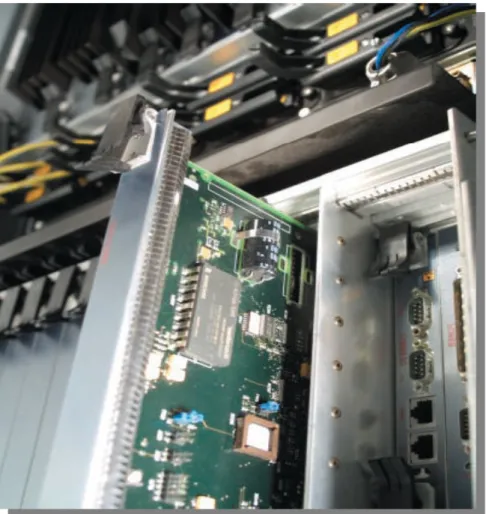
The so-called transponders are cards which can be simply inserted into the apparatus (as shown in Figure 2.1) and which are configured for a certain frequency – they can have a protection line or not, depending on the necessities.
A certain traffic (for example SDH or Gigabit Ethernet) is injected onto a chosen card and is converted by the card’s optical equipment into a signal with the desired frequency – frequency which will be sent onto the external optical infrastructure and then received at the next PMA32.
Figure 2.1 - A view on the mechanical apparatus in the PMA-32
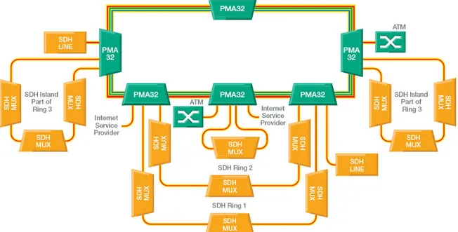
In Figure 2.2 there is an example of a PMA 32-based architecture, showing a ring with 6 PMA’s and SDH / ATM networks.
46
Figure 2.2 - An example of PMA-based architecture
2.3 MULTIPLEXING/DEMULTIPLEXING
IN THE PMA-32
2.3.1 QUICK INTRODUCTION TO THE SYSTEM UNITS
The PMA–32 multiplexer adds and drops only at the optical layer. It is because the content of the traffic is virtually transparent to the PMA–32 that a wide variety of traffic can be handled.
The PMA–32 equipment involves 32 wavelengths plus an additional Supervisory Channel (OSC) for carrying Overhead information.
A pair of fibres carry 32 bidirectional optical channels by WDM on each line port. Each PMA–32
has two WDM line ports.
The TX LINE UNITS multiplex the internal PMA–32’s optical channel signals coming from the Add/Drop units and from the Channel Control unit onto the line signal, adding the OSC. The resulting optical signal contains up to 32 channels in the 192.1 and 195.2 THz range plus the 33rd OSC at a nominal 1510nm. The data rate of the optical channels can vary from 50Mbit/s to 2.5Gbit/s.
The RX LINE UNITS receive the WDM signal containing the 32 optical traffic signals and the 33rd supervisory channel and splits it into:
- through-traffic which is passed to the Channel Control Unit
- traffic destined for the transponding channel units which is passed to the Add/Drop unit.
47
The CHANNEL CONTROL UNIT sits between the West and East line cards and provides variable attenuation of each of the 32 optical channels. This allows levelling of the through-channels or blocking of any channels added/dropped at that particular node. The TRANSPONDING CHANNEL UNITS are able to receive from the RX line the dropped optical channel and to send an added optical channel to the TX line.The ADD/DROP UNITS distribute incoming optical channels to tributary slots (drop function) and
combine optical channels from tributary slots ready to be added to through channels (add function). There are versions of Add/Drop units to support 8, 16 or 32 transponder channel slots. Just notice that versions for 32 transponding channel slots restrict each slot to a particular optical channel, but the other two do not do that.
All internal traffic is carried optically via either the optical backplane if both source and destination are in the same sub-rack, or via backplanes and optical fibre interconnect cable if they are in different sub-racks.
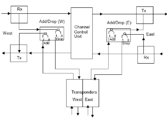
2.3.2 INTERNAL TRAFFIC ARCHITECTURE
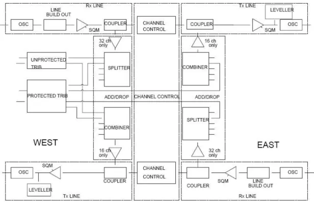
Figure 2.3 – Internal traffic architecture of a PMA-32
We’ll first of all try to explain the fundamental internal behaviour of the PMA-32: Let’s have a look at the West TX line in the following sub-picture:
48
Figure 2.4 – West TX line detailed view
A tributary connected to the WEST TRANSPONDER is sent to the ADD/DROP UNIT, where it is added to the TX LINE, together with other eventual added channels coming from other tributaries.
Secondly, there’s another component which is redirected to the West TX LINE: the pass-through channels coming unchanged from the CHANNEL CONTROL UNIT.
A Coupler is supposed to make a unique signal containing the added signals and the pass-through signals coming from the Control unit.
The transmitted signal is supposed to go through a fibre cable which assumes the logical topology of a ring, and it should be received by the same PMA at the East RX side.
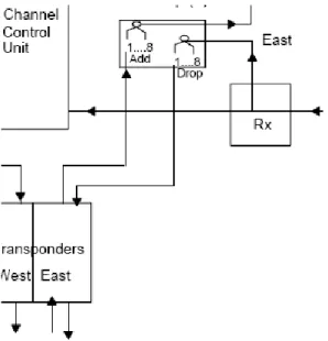
Let’s have a look at the East RX line:
Figure 2.5 – East RX line detailed view
We’ll have a signal that must be multiplexed in the different wavelengths: some of them will be passed through the CHANNEL CONTROL UNIT without being treated, and others can be dropped using a splitter which is contained in the East ADD/DROP UNIT.
The dropped wavelength is then sent to the EAST TRANSPONDER, which can receive the signal coming from the ring which was supposed to be addressed to it.
49
The remaining units shown in Figure 2.3 – the West RX line and the East TX line – do behave the same way, and are usually considered a protection ring, a kind of redundancy signal in case some fibre cables should not work properly.The operator could also decide to use West TX and West RX for the main signal, and East TX and East RX for the protection line – but we will see this in detail in the testing chapter.
The general traffic architecture of the PMA–32 is shown in Figure 2.6.The diagram shows the main functional traffic units within the PMA–32, these being the line interface units, transponding channel units and channel control units.
Line RX to Channel Control Interface
This interface transfers the combined optical wavelengths from the receive line unit to the Channel Control unit via a single fibre on the optical backplane.
Channel Control to Line TX Interface
This interface transfers the ‘through traffic’ (Un–blocked) optical wavelengths from the Channel Control unit to the transmit line unit via a single fibre on the optical backplane.
Figure 2.6 – Internal traffic interfaces
Add/Drop Unit Interface to RX Side of Transponder Interface
It transfers the combined optical wavelengths from the line Add/Drop unit
to a connection panel on the Core sub-rack via N optical fibres (where N depends can be 8, 16 or 32) on the optical backplane. The combined optical signals are then transferred from the connection panel on the Core sub-rack to a connection panel on the Extension sub-racks via fibre cables. From the connection panel on the Extension sub-rack the combined optical wavelengths are transferred to the transponders via a single fibre on the optical backplane.
50
TX Side of Transponder to Add/Drop Interface
It has the role of transferring the single optical wavelengths from the transponder units to a connection panel on the Extension sub-racks via a single fibre on the optical backplane. These optical signals are then transferred from the connection panel on the Extension sub-racks to a connection panel on the Core sub-rack via fibre cables. From the connection panel on the Core sub-rack the optical signals are transferred to the Add/Drop unit via N optical fibres.
Line Rx to Add/Drop Unit Interface
This interface transfers the combined optical wavelengths from the Line Rx unit to an 1:8, 1:16 or 1:32 splitter (depending on whether we have an 8,16 or 32 channel add/drop unit ) on the Add/Drop Unit via a single fibre on the backplane.
Add/Drop Unit to Line Tx Unit Interface
This interface transfers the combined optical wavelengths from the 8:1, 16:1 or 32:1 combiner on the Add/Drop Unit to the Line Tx Unit via a single fibre also on the backplane.
51
52
2.4 THE CONCEPT OF
CROSS-CONNECTIONS
PMA–32 tributary interfaces are capable of carrying the full line capacity of external networks. Internal Line to Line and Line to Tributary /Tributary to Line cross connection functionality is provided within the PMA–32.
There are three main types of cross-connection we can determine:
-
Line to Line.-
Line to Tributary and Tributary to Line.-
Wavelength interchange
PMA–32 does not support Tributary to Tributary connections.
The internal cross–connect functionality within a PMA–32 is provided by the combination of two units:
-
The Channel Control Unitwhich sits between the receive and transmit line cards and provides variable attenuation of each of the 32 optical channels, thus obtaining levelling of the through-channels or blocking of any channels added/dropped at that particular node.
-
The Add/Drop Unitsone handling channels in the East/West direction and the other for the West/East direction.
.
- Line to Line (PASS-THROUGH) -
Cross–connections of this type are carried by the Channel Control Unit, which connects 32 optical signals at 32 wavelengths, from one line card (East or West) to the other line card (West or East).
- Line to/from Tributary (CROSS CONNECTION) -
It is also possible to add/drop up to 32 optical signals from/to the corresponding transponder cards. The number of signals that can be added or dropped depends on the types of Add/Drop cards installed: 8, 16 or 32 channels.
Pass-through connections and cross-connections are the name which we are
going to use in the next chapter to simply distinguish the 2 typologies of
connection.
These two different possibilities will be detailed and deeply explained during our
testing activity in the paragraph “PMA32 CONFIGURATION”.
- Wavelength Interchange -
Wavelength Interchange is a process of converting one Photonic Channel to another Photonic Channel at a different wavelength. Any of the 32 Optical Channels can be
53
cross–connecting _1 to Trib 1, externally linking Trib 1 o/p to Trib 2 i/p and cross– connecting Trib 2 to Line _2. The OCh path overhead can be passed through the external Trib1/Trib2 links.2.5 PMA-32 ALARMS
There are defect monitors provided within the PMA to monitor all types of defect.
They detect conditions that may indicate a defect in the equipment itself, or a defect not due to the equipment.
Defect monitors are implemented either in hardware (to detect traffic conditions or card hardware deviations), or in software (to detect problems with memory devices, logical operator configuration mismatches or threshold analogue monitors).
The system validates all defects and, if the defect passes validation, generates an alarm event. This section details the alarm information that is shown to the operator in the Local Craft Terminal.
Alarm events flag defects both within the environment of the NE (by a local alarm scheme) and remotely from the NE (by filtered message-based reports).
Due to the modular nature of the PMA, any single defect can be detected at multiple points within the PMA. Where this occurs, each defect is given a unique identity that indicates its source.
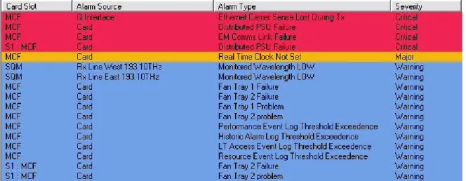
There are cases where many alarms are shown and it seems not too easy to understand how to solve every single alarm (look for example at Figure 2.7).
This book also wants to be an easy guide to the most common problems one has to face when trying to configure the system for the first time, or to reconfigure it with particular schemes or goals – some possible scenarios will be examined in the chapter regarding the tests on the PMA-32.
Figure 2.7 – Example of multiple alarms on a PMA32
As for now we’ll just have a look at the most common alarms that are shown in the management software.
54
2.5.1 THE MOST COMMON ALARMS
ADD CHANNEL FAILURE
DESCRIPTION
-Related to TX Line Unit:
The leveller attempted to add a channel but was unsuccessful.
This may mean that the source is broken or that the channel power is coming up in the wrong place; that is, the inter–subrack cabling is different to that logically configured. -Related to CCU, Transponder:
The unit attempted to add a channel but did not receive any ’Off’ commands from the leveller.
IMPLICATION
The channel will be turned off; you must decide whether to attempt a retry. REMEDY
Inspect the inter–subrack cabling against the stored configuration. If these checks fail to identify any faults, replace the unit reporting this alarm.
Usually the ADD CHANNEL FAILURE alarm appears when something is wrong in the cabling inside the PMA, so in case an alarm like that is detected the best thing is to change the slot where the tributary rising the alarm has been inserted or to check the cables connecting core and sub-rack.
ALS
This alarm raises when there’ s no fibre cable connected to a certain tributary transponder. It’s usually shown together with “LOSS OF SIGNAL” and “CLIENT INPUT LOSS OF SIGNAL” alarms.
BDI (Backward Defect Indicator)
DESCRIPTION
A receiver error has been encountered at the PMA sourcing the overhead in question. IMPLICATION
The section BDI is raised because of Optical Transmission Section (OTS) Loss–of–Signal and Trace Identifier Mismatch.
The path BDI is raised because of Payload Type Identifier (PTI) Mismatch, PTI Unequipped, Trace Identifier Mismatch, and Optical Channel Loss–of–Signal.
REMEDY
Clear the fault(s) at:
– the NE sourcing the signal received by the card raising this alarm
– at the other end of the OTS section, or Optical Channel trail for Rx line units and transponders respectively.
55
CARD IN UNCONFIGURED SLOT
DESCRIPTION
A card has been inserted into the given slot, but the given slot is supposed to be unoccupied.
IMPLICATION
The card cannot be used. Perhaps the card has been inserted into the wrong slot by mistake.
REMEDY
Configure the slot to accept the card or remove the card from the unconfigured slot.
CARD OUT
DESCRIPTION
The card has been removed from, or has never been present in, a slot that is configured. IMPLICATION
Traffic or supervisory functions are being lost. REMEDY
Re-insert the card in the appropriate slot, or unconfigure the slot from the LCT.
CONNECTED PATH ABSENT
DESCRIPTION
A connection has been defined for a channel that is not being transmitted from the preceding PMA.
IMPLICATION
Either the preceding PMA has not been configured correctly, or possibly a connection has been defined for the wrong channel at this PMA.
REMEDY
Make sure the connection that has been defined is correct. If so, make sure the previous PMA-32’s have been configured to carry the channel indicated by the alarm, and that they have no O-Ch alarms related to it.
In other words, an alarm like this occurs on a PMA when in a preceding one there is an ADD CHANNEL FAILURE alarm, that is to say there’s a problem while trying to transfer a tributary from the sub-rack to the core, during an add operation.
DISTRIBUTED PSU FAIL
This alarm is safety critical under certain conditions and should not be inverted or disabled. DESCRIPTION
56
IMPLICATIONThe unit whose onboard PSU has failed must be replaced. In the case of the hub card, this has two PSU’s, so look also for the Hub PSU Fail alarms. If both hub PSU’s have failed, you must replace the card immediately; if only one has failed then the card will still operate and you can replace it later if you wish.
REMEDY
Identify the card with a failed PSU. Such a card will have its green LED off, and its red LED on. For cards with onboard processors, the Controller/Comms Card will be indicating a ’Card/Slot Fail’ alarm. Replace the faulty unit.
EM COMMS LINK FAILURE
DESCRIPTION
This indicates that the Controller/Comms Card is unable to communicate with its designated EM.
REMEDY
Inspect the comms link.
FAN TRAY FAIL
DESCRIPTION
One of the cooling fans has failed or an over–temperature condition exists. IMPLICATION
If all fan fails are raised there is a possibility that the rack will get hot. REMEDY
Make sure that the ambient temperature is below the maximum specification and that airflow is not blocked. If these checks fail to identify any faults, remove the fan unit showing a red LED indication. Clean or replace the filter. If this does not cure the problem, replace the fan cassette.
LOSS OF SIGNAL
DESCRIPTION
The PMA is not receiving any signal. IMPLICATION
This alarm is raised as a result of other alarm conditions:
-Client Input: Created by logically ’OR’ing Client Input CDR Out of Lock defect and the Client Input Power Low.
-Rx OCh: Created by logically ’AND’ing OCh–OH Loss of Frame defect and the Input Fail Threshold signal.
REMEDY
Inspect the signal source on other equipment for alarms indicating a transmit fault, and the interconnecting fibres for continuity. If these checks fail to identify any faults, replace the unit reporting this alarm.
57
MONITORED WAVELENGTH HIGH
DESCRIPTION
The PMA is receiving or transmitting an optical signal that is higher than pre–defined wavelength limits.
REMEDY
Locate the transponder sourcing the optical channel indicated by this alarm. Note that it may be on another NE. Replace the transponder.
MONITORED WAVELENGTH LOW
DESCRIPTION
The PMA is receiving or transmitting an optical signal that is lower than pre–defined wavelength limits.
REMEDY
Replace the card generating the alarm.
PRESENT PATH UNCONNECTED
DESCRIPTION
No connection has been defined for a channel that is being transmitted from the preceding PMA.
IMPLICATION
Either the preceding PMA has not been configured correctly or possibly a connection has been defined for the wrong channel at this PMA. Note that, as default, this channel is passed through the PMA.
REMEDY
Ensure that the connection that has been defined is correct. If so, make sure the previous PMA-32s have been configured to carry the channel indicated by the alarm and that they are not reporting O-Ch alarms for the indicated channel.
In other words an alarm like this is raised when we delete a cross connection on a PMA for example, so there is a frequency which is supposed to be received at a second PMA, while at the first one the cross-connection has been cancelled.
REAL-TIME CLOCK NOT SET
DESCRIPTION
The NE’s real–time clock has not been set, and so time stamping will not be accurate. In practice, this alarm should only occur when the Controller/Comms Card is inserted into the sub-rack, or on restoration of power to the sub-rack following a period of power loss. REMEDY
58
SNCP MODE MISMATCH
DESCRIPTION
Either end of the bi–directional SNC is set to different modes (revertive and non– revertive).
IMPLICATION
The ’dual ended’ switching will be defeated, effectively the switching will be ’single ended’. REMEDY
Examine the SNC modes at each end of the connection.
WRONG CARD FITTED
DESCRIPTION
The card in the given slot is not the same type as that configured. IMPLICATION
The full range of services expected from the card in that slot may not be available. REMEDY
Re–configure the slot to accept the fitted card or insert a correct card type in the slot.
2.6 TRAFFIC PROTECTION
There are two forms of traffic protection provided in the PMA-32: - SNC PROTECTION- 1+1 CLIENT PORT PROTECTION
Particular attention will be paid for the PMA-32 Sub-network Connection Protection (SNCP) mechanism is designed to protect against equipment failure within a PMA-32 network. Equipments such as SDH/SONET elements will continue to use their own protection schemes with the PMA-32 providing the number of fibers required by those elements.
We’ll analyze the protection features in the chapter regarding the tests on the PMA32, so to help the reader understand the concepts together with the apparatus’ details.
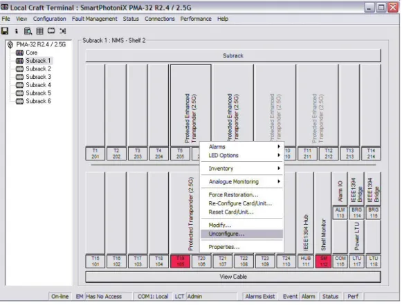
2.7 OPERATOR CONTROL
The final goal of this book is to test the PMA32 and create a PMA-based photonic core; everything we are going to do in the next chapter will involve the Marconi PMA32 software called LCT.
Operator monitoring, control, commissioning and fault diagnosis is provided from either a remotely located Element Management System or more simply at any element of a network by a Local Terminal (LCT), which is shown in Figure 2.8.