GIANNONE Francesco
Implementation and Experimental Evaluation
Of a Virtualised 5G Network
Implementation and Experimental Evaluation
Of a Virtualised 5G Network
for URLLC Services
Author
Francesco Giannone
Supervisor
Prof. Luca Valcarenghi
Tutor
Prof. Piero Castoldi
International Ph.D. Program
in Emerging Digital Technologies
1 Introduction 1
1.1 Novel contributions . . . 4
1.2 Thesis Structure . . . 5
2 History of mobile network 7 2.1 Introduction . . . 7 2.2 1G - Analog cellular . . . 9 2.3 2G - Digital cellular . . . 10 2.4 3G - Mobile broadband . . . 11 2.5 4G - Native IP networks . . . 14 3 From LTE to 5G 15 3.1 Introduction . . . 15
3.2 LTE network architecture . . . 17
3.2.1 Multiplexing/Multiple Access Mechanism in LTE . . . 19
3.2.2 Coding and Modulation in LTE . . . 20
3.2.3 Radio Channel Bandwidth in LTE . . . 21
3.2.4 LTE Technological Advancements . . . 21
3.2.5 Towards the 5G . . . 24
3.3 The 5G Next Generation Mobile Network . . . 25
3.3.1 5G Core Network Architecture . . . 26
3.3.2 5G Radio Access Network . . . 32
3.3.3 Virtualization in 5G . . . 34
3.3.4 Multi-Access Edge Computing achieves 5G goals . . . 35
3.3.5 Reliability in 5G . . . 37
3.3.6 5G Slicing . . . 39
4 OpenAirInterface and the ARNO-5G Testbed 45 4.1 Introduction . . . 45
4.3 ARNO-5G Testbed . . . 47
5 NG RAN Virtualisation: Deployment and Performance Analysis 51 5.1 Introduction . . . 51
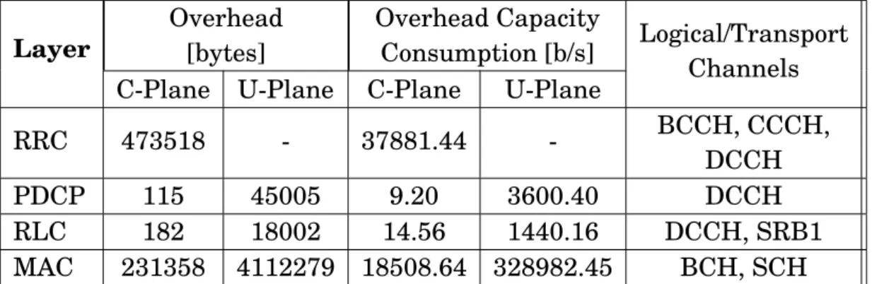
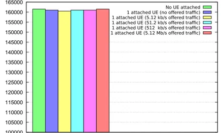
5.2 Performance Evaluation #1: Protocol Stack Layer overhead . . . 53
5.3 Performance Evaluation # 2: Latency limits of gNB functional split . 59 5.4 Performance evaluation #3: Increasing the DUs . . . 63
5.5 Performance evaluation #4: Moving to a virtual environment . . . . 67
5.6 Performance evaluation #5: Virtualisation Impact . . . 74
5.7 Conclusion . . . 83
6 Multi-access Edge Computing (MEC) in 5G Networks 85 6.1 Introduction . . . 85
6.2 MEC Deployment in next Generation 5G networks . . . 86
6.2.1 5G & MEC System architectures . . . 87
6.2.2 MEC deployment scenarios . . . 90
6.3 MEC for an advanced automotive communications . . . 91
6.3.1 MEC as solution for for the AD applications . . . 91
6.3.2 MEC in the Automotive use cases . . . 92
6.4 A MEC-Based VRU Warning System . . . 94
6.4.1 System Architecture . . . 95
6.4.2 CAM Client: the VRU app . . . 96
6.4.3 Collision Avoidance Messages (CAMs) . . . 97
6.4.4 CAM Server . . . 98
6.4.5 VRU Viewer . . . 99
6.4.6 VRU Warning System Performance evaluation . . . 100
6.5 Orchestrating Heterogeneous MEC-based Applications . . . 101
6.5.1 CVSO Architecture and Components . . . 102
6.5.2 An ILP Formulation for QoE-aware video representation se-lection . . . 106
6.5.3 Testbed description . . . 108
6.5.4 Experimental Methodology . . . 109
6.5.5 Experimental Results . . . 110
6.5.6 ILP solution performance . . . 112
7 Reliability in 5G networks 119
7.1 NG Core Reliability . . . 120
7.1.1 The SoftFIRE Middleware Framework . . . 121
7.1.2 Considered scenario and the proposed resilience scheme . . . 121
7.1.3 Experimental Results . . . 123
7.2 NG RAN Reliability . . . 124
7.2.1 PROnet Testbed Configuration . . . 125
7.2.2 1:1 + R protection and restoration mechanism . . . 127
7.2.3 1 + 1 + R protection and restoration mechanism . . . 129
7.2.4 Experimental Results . . . 131
7.3 Lightpath Recovery and Functional Split Adaptation in NG RAN . . 133
7.3.1 Considered Scenario and Two-Step Recovery Scheme . . . 135
7.3.2 Simulation Scenarios . . . 139
7.3.3 Experimental Scenarios . . . 140
7.3.4 Results . . . 144
7.4 Conclusion . . . 148
8 Slicing in 5G networks 151 8.1 Bringing the ”Network Slicing” into 5G networks . . . 152
8.1.1 Resource and Service Orchestration . . . 154
8.2 5G Network Slice Deployment . . . 158
8.2.1 5G Network Slice: Preliminary Deployment . . . 159
8.2.2 An Improved 5G Network Slice Deployment . . . 160
8.3 Conclusion . . . 163
9 Closing discussion 165 9.1 Summary of the thesis . . . 165
1.1 Orchestration in 5G . . . 1
1.2 Ability to stream ultra high-definition video in 5G . . . 2
1.3 Future 5G Wearables . . . 2
1.4 5G Connected Vehicles . . . 3
2.1 Karl Arnold drawing of public use of mobile telephones . . . 8
2.2 Evolution of G-Technology . . . 9
2.3 Motorola DynaTAC . . . 9
2.4 Personal Handy-phone System mobiles . . . 10
3.1 LTE network architecture . . . 18
3.2 Services in Future 5G Networks . . . 26
3.3 Point-to-Point NG-Core Architecture . . . 29
3.4 Service-Based NG-Core Architecture . . . 30
3.5 Flexibility for 5G RAN Functional Units . . . 33
3.6 Flexibility for 5G RAN Functional Units . . . 33
3.7 Flexibility for 5G RAN Functional Units . . . 34
3.8 Flexibility for 5G RAN Functional Units . . . 38
3.9 Highly-available 5G Network Topologies . . . 39
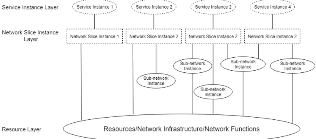
3.10 Slice Concept . . . 40
3.11 High level function of roles . . . 41
3.12 Interaction between slice management functions (3GPP) and ETSI NFV Architecture . . . 42
4.1 OAI Architecture . . . 46
4.2 ARNO-5G testbed block diagram . . . 48
5.1 An example of considered functional splits for 5G systems . . . 54
5.2 Performance Evaluation # 1: gNB-UE messages exchange . . . 58
5.3 Performance Evaluation # 1: CFSO measurements . . . 59
5.5 Performance Evaluation #2: Midhaul bandwidth (5 MHz) . . . 61
5.6 Performance Evaluation #2: Midhaul bandwidth (10 MHz) . . . 62
5.7 Performance Evaluation #2: Midhaul latency limit . . . 62
5.8 Performance Evaluation #23: ARNO-5G Configuration . . . 64
5.9 Performance Evaluation #3: ALB . . . 66
5.10 Performance Evaluation #3: AJB with a latency value close to the ALB 66 5.11 Performance Evaluation #3: AJB with a latency far to the ALB . . . 67
5.12 Performance Evaluation #4: ARNO-5G Configuration . . . 68
5.13 Performance Evaluation #4: Midhaul ALB . . . 72
5.14 Performance Evaluation #4: Midhaul AJB with latency close to the ALB . . . 73
5.15 Performance Evaluation #4: Midhaul AJB with a fixed latency far from the ALB . . . 74
5.16 Performance Evaluation #5: ARNO-5G Configuration . . . 75
5.17 Performance Evaluation #5: Functional Split Options . . . 76
5.18 Performance Evaluation #5: Scenario 1 . . . 76
5.19 Performance Evaluation #5: Scenario 2 . . . 77
5.20 Performance Evaluation #5: Scenario 3 . . . 77
5.21 Performance Evaluation #5: Midhaul ALB . . . 78
5.22 Performance Evaluation #5: ALB trends as a function of channel bandwidth . . . 79
5.23 Performance Evaluation #5: Midhaul AJB with a fixed latency close from the ALB . . . 80
5.24 Performance Evaluation #5: Midhaul AJB with a fixed latency far from the ALB . . . 81
5.25 Performance Evaluation #5: Midhaul ALB in the anti-affinity con-straint analysis . . . 82
5.26 Performance Evaluation #5: Midhaul ALB in the scalability analysis 83 6.1 5G Service-Based Architecture and a generic MEC system architecture 88 6.2 MEC physical deployments . . . 90
6.3 MEC-Based VRU Warning System Architecture . . . 95
6.4 MEC-Based VRU Warning System Block Diagram . . . 95
6.5 MEC-Based VRU App . . . 96
6.6 CAM Server Flow Chart . . . 98
6.8 Experienced CAM Latency from VRU to CAM server. . . 100
6.9 CVSO Architecture . . . 103
6.10 ARNO-5G Configuration for CVSO performance evaluation . . . 108
6.11 QoE for U E1 (CQI=15) . . . 111
6.12 QoE for U E2 (CQI=10) . . . 112
6.13 Average QoE Comparison . . . 113
6.14 CPLEX Solving Time . . . 114
6.15 CPLEX Solving Time for the first 100 mobile users . . . 114
6.16 Overall Solving Time . . . 115
7.2 Proposed scheme experimental evaluation setup . . . 122
7.1 RAN and Core network deployment in SoftFIRE environment . . . . 122
7.3 Capture (at the vOAISIM VNF) of ICMP messages exchanged be-tween the vEPCa and vEPCr . . . 123
7.4 PROnet Testbed . . . 126
7.5 1:1 + R protection and restoration mechanism . . . 128
7.6 1:1 + R protection and restoration mechanism . . . 129
7.7 Wireshark capture (CU side) capturing echo requests and replies be-tween the CU and the DU . . . 132
7.8 Metro midhaul architecture . . . 136
7.9 Two-step recovery scheme flow chart . . . 138
7.10 Scenario considered for the experimental evaluation . . . 140
7.11 Lightpath transmission adaptation FSM . . . 141
7.12 Mean overall recovered rate through transmission parameter adap-tation versus offered traffic load, with soft failures introducing an OSNR penalty of 2 dB. . . 145
7.13 Mean overall recovered rate through transmission parameter adap-tation versus soft-failure OSNR penalty, with a traffic load of 100 Erlang. . . 146
7.14 Capture, at the UE, of ICMP messages exchanged between the UE and the EPC . . . 147
8.1 VS, SO and MTP vertical services instatiation high level workflow . 153 8.2 Overview of 5GT-SO subsystems and their interactions . . . 155
8.3 The Preliminary 5G Network Slice Deployment Testbed . . . 160
8.4 The Preliminary 5G Network Slice Deployment Instantiation Work-flow . . . 161
8.5 Network Service Representation . . . 161 8.6 The Improved 5G Network Slice Deployment Testbed . . . 163
3.1 LTE vs LTE-A . . . 23
3.2 Virtualized vs. Cloud-native Networks . . . 28
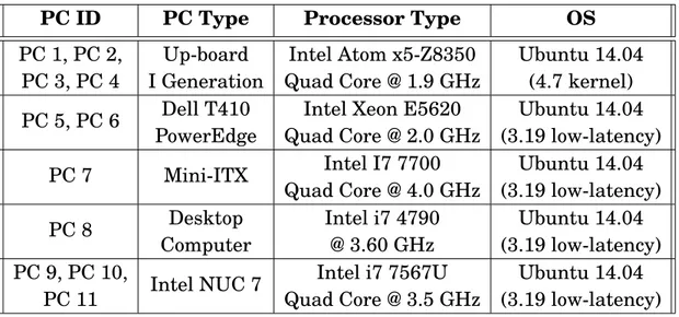
4.1 Major hardware attributes of the ARNO-5G testbed machines . . . . 49
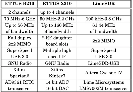
4.2 ARNO-5G RF Devices specifications . . . 50
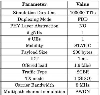
5.1 Performance Evaluation # 1: Simulation Parameters . . . 57
5.2 Performance Evaluation # 1: Layer Overhead Results . . . 58
5.3 Performance Evaluation #3: Experimental parameters . . . 65
5.4 Performance Evaluation #5: Experimental Scenarios . . . 75
5.5 Performance Evaluation #5: α and β coefficients . . . 79
6.1 V2X Groups & MEC Relevance . . . 93
7.1 Midhaul Requirements . . . 135
7.2 Metropolitan Area Capacity Requirements . . . 136
5G Is Coming. Here is how immersive smartphones, autonomous cars and billions of intelligent sensors could transform your life.
Figure 1.1: Orchestration in 5G
The fifth generation of cellular tech-nology, 5G, will offer much more than faster phones. Its first phase, sched-uled to begin in 2019, will improve smartphone responsiveness. Soon af-ter, 5G may also start to enhance many other aspects of your daily life, from au-tomotive safety to your entertainment and your view of reality. For instance, your 5G smartphone will be able to stream ultra high-definition video at
gi-gabit speeds, with enough consistency to enable immersive virtual reality experi-ences.
In a subsequent phase, 5G could also provide a dependable link between au-tonomous vehicles, allowing cars to share their ”intentions” and communicate di-rectly with one another - and even with pedestrians - for safer, more efficient com-mutes.
5G, however, will not just be another ”G” delivering faster speeds. Such standard brings technologies and facilitation that will allow to unite billions of devices, with the potential to transform not only your smartphone but also your home, vehicle, job, industry and community. Indeed, due to the inabil-ity in terms of power of our current generation of wireless internet devices to fully bring some services, such as virtual and augmented reality, into the daily life, 5G will be the only possible solution. That’s because, for instance the ex-tended reality - an umbrella term encompassing virtual reality, augmented real-ity and everything in between - pushes connectivreal-ity to its limits: it requires a
uniform high-speed connection, increased network capacity and minimal delays.
Figure 1.2: Ability to stream ultra
high-definition video in 5G
5G will be able to support virtual teleconferencing. Say you are stream-ing a basketball game to your headset and receiving a 360-degree view of the court. However, you do not want to just watch the game; you also want to pause the action and brush shoulders with players. 5G will have the poten-tial to provide enough capacity and low latency for you to immerse yourself in the game without delays or data con-gestion. Who wants to enter a virtual world, after all, only to be dragged out by slowed movements or scenery glitches? Extended reality enabled by 5G will also allow the users to virtually enter the same room as friends and family, with few delays or dropped connections. With the addition of haptic gloves - accessories that allow people to touch and feel in virtual reality - you might even be able to hold your child’s hand while you are in another country.
Further, along in our 5G future, wearable technologies will join forces with the massive internet of things, IoT, allowing billions of intelligent, connected sensors to do more than tell you how many steps you’ve walked or how fast your heart is beating. Wearables of today provide limited information, but with the 5G mas-sive IoT, they’ll be able to connect to what’s going on around us all of the time.
Figure 1.3: Future 5G Wearables
This is the 5G future: sensors could constantly interact with your wearable devices and with one another, creating the ability to monitor everything from your morning commutes to your factory goods to your children. A simple vibra-tion from a wearable on your wrist, for instance, could tell you that only one bike remains at your usual bike-share location. As you rush over, the same
5G massive IoT will have the ability to scale to billions of connected sensors. How would this play out? A chain of sensors could track and optimize goods as they move from their sources to your home. Take your clothes, for instance. At the beginning of the supply chain, sensors in the ground and in machinery could connect over the 5G network to farm cotton more efficiently. Self-driving trucks with sensors could then transport the raw cotton to a factory, where a wireless automated robot could transform the raw material into samples, based on size and pattern. Designers fitted with AR glasses could collaboratively turn the rough samples into templates for an entire production run. Finally, the shirts could be uploaded to an online shelf, where you could try them on using a VR device. This entire process, from farm to closet, would be brought to you by the 5G network.
Figure 1.4: 5G Connected Vehicles
5G will also enable ultra-reliable and low-latency communication. Au-tonomous vehicles and high-precision manufacturing, among other use cases, will need these qualities to thrive. 5G, at a later stage, could allow au-tonomous vehicles to establish a direct link between each other that bypasses network towers and diminishes urgent communications delays. This means a vehicle could instantly receive alerts to stop or change course if a collision seems imminent, even if the danger is beyond the range of its cameras and radar. In addition, 5G-enabled vehicles could connect with smart city infrastructure like traffic lights and street signs, improving traffic management. With 5G communi-cations between autonomous vehicles, cars could share their intentions and know intended paths, allowing them to plan more safely and efficiently. Therefore, steering wheels could disappear, with cars redesigned as living spaces: basically couches or offices on wheels. With 5G-enhanced mobile internet, your car will be able to stream ultra high-definition video, and even VR, while you travel. Passen-gers could easily work as they ride, perhaps changing the entire nature of their commutes.
the world in countless ways. And fully immersive virtual worlds, massive networks of connected sensors and safer roadways are just the beginning.
The imagination of our future is therefore a networked society with unbounded access to information and sharing of data which is accessible everywhere and ever time for everyone and everything. Present wireless based technologies, like 3GPP LTE technology, HSPA and Wi-Fi, will be incorporating new technology compo-nents that will be helping to meet the needs of the future. Nevertheless, there may be certain scenarios that cannot be adequately addressed along with the evo-lution of ongoing existing technologies. The instigation of a completely new wire-less based technologies will complement the current technologies which are need for the long term realization of the networked society [1]
1.1 Novel contributions
This thesis provides contributions to the state of the art regarding the architec-ture and performance of the LTE and 5G mobile networks, from the conceptual and the experimental point of view. The thesis covers both research and imple-mentation aspects, especially because almost everything was developed in an ex-perimental setup to develop and analyze a standard compliant 5G network.
The main objective of the thesis is the development of a standard compliant 5G network and all the components belonging to it. In such a network, firstly a deep analysis of its performance have been performed. This is because the need to un-derstand if some typical 5G services and applications, such as autonomous vehicles collision application and ultra high-definition video streaming applications could be deployed exploiting the deployed 5G network.
To achieve these goals, the starting point has been the investigation of one of the main open source 5G emulation platform, the OpenAirInterface emulation plat-form. After a first phase in which the platform has been analyzed and set in the TeCIP Institute laboratory, it has been extended with new features and capabili-ties and adopted to setup a standard compliant 5G network. A deeply analysis and experimental measurements of latency and jitter experienced in the 5G network have been performed.
The next objective was the introduction in the 5G network of the so-called Multi-access Edge Computing (MEC). Edge computing as an evolution of cloud comput-ing brcomput-ings application hostcomput-ing from centralized data centres down to the network edge, closer to consumers and the data generated by applications. Edge computing
is acknowledged as one of the key pillars for meeting the demanding Key Per-formance Indicators (KPIs) of 5G, especially as far as low latency and bandwidth efficiency are concerned. This objective is mainly realized thanks to the collabo-ration with EURECOM in Sophia-Antipolis during the period abroad. Exploiting the MEC, two applications as part of our contribution to the 5G-TRANSFORMER project related to the road safety and automotive infotainment have been deployed in the autonomous vehicles scenario.
The 5G network architecture, will be heavily based on virtual network func-tions(VNFs). Thus, in a scenario where network functions are virtualized, both hardware and software failures assume the same importance, and their reliability shall be guaranteed. Similarly, reliability at service chain level is important to as-sure proper service availability features to application service platforms deployed by verticals. Therefore a study of the reliability in 5G networks has been also per-formed in the conclusion of my Ph.D. Different protection mechanisms have been proposed and experimentally analysed for both 5G core and access networks.
Last but not least, this work also pursued a really challenging goal: we were able to demonstrate a 5G network slice deployment in the ARNO testbed by using the 5G-TRANSFORMER architecture and offer a mobile/edge connectivity service with virtualized functions.
1.2 Thesis Structure
This Ph.D. thesis focuses on the design, implementation and experimental vali-dation of a 5G network.
Chapter 2 gives a broad overview of the history of the mobile network start-ing from the first generation of mobile network (1G) until nowadays Long Term Evolution.
Chapter 3 gives a broad overview of the LTE architecture and key points and introduces the 5G Next Generation mobile network design and strong aspects. In this chapter, it is specified the difference between LTE and 5G network and the novelties introduced by the 5G.
Chapter 4 overviews the software platform and the hardware utilised in the TeCIP Laboratory a standard-compliant 5G network.
Chapter 5 presents an evaluation of how different virtualization technologies can afflict the network performances in terms of latency and jitter when different 5G network components are virtualised and different gNB functional splits are
considered. The measured latency and packet jitter (i.e., packet delay variation) ”budget” are computed in all the possible combinations and compared with the scenario when all the network components belonging the 5G network are deployed in bare metal.
Chapter 6 illustrates the role and explains the benefits of Mobile-access Edge Computing introduction in a 5G network. Some possible solutions to deploy and integrate MEC in the 5G system are presented. Finally, it presents two deployed MEC-based applications in the automotive scenario.
Chapter 7 introduces and describes the reliability in the 5G networks, focusing on both the core network and access network. Firstly shows a proposed protection mechanism able to recover vEPC failures by means of a vEPC in ”hot backup”. Both working vEPC and backup vEPC are deployed in multiple Network Function Virtual Infrastructure Points of Presence (NFVI-PoPs) made available by the fed-erated testbeds belonging to the SoftFIRE project.The goal is to evaluate the Ser-vice Recovery Time (SRT), that is the time required to regain user equipment (UE) connectivity, when the proposed resilient scheme is deployed in different NFVI-PoPs. Then, a Next Generation RAN testbed whose midhaul are realized using a highly reliable two layer Ethernet-over-DWDM transport network prototype is described. Finally, the application and experimental evaluation of two protection mechanisms to achieve reliable midhaul transport networks when using the func-tional split 7-1 option is presented.
Chapter 8 demonstrates a 5G network slice deployment in the ARNO test-bed by using the 5G-TRANSFORMER architecture and offer a mobile/edge connectivity service with virtualized functions.
Finally, Chapter 9 closes with a summary discussion, which includes an overview of the achieved results and contributions, as well as the list of scientific production of the Ph.D. period.
2.1 Introduction
While the transmission of speech by radio has a long history, the first devices that were wireless, mobile, and also capable of connecting to the standard tele-phone network are much more recent. The first such devices were barely portable compared to today’s compact hand-held devices, and their use was clumsy [2].
Along with the process of developing a more portable technology, and a better in-terconnections system, drastic changes have taken place in both the networking of wireless communication and the prevalence of its use, with smartphones becoming common globally and a growing proportion of Internet access now done via mobile broadband.
Before the devices existed that are now referred to as mobile phones or cell phones, there were some precursors. In 1908, a Professor Albert Jahnke and the Oakland Transcontinental Aerial Telephone and Power Company claimed to have developed a wireless telephone. They were accused of fraud and the charge was then dropped, but they do not seem to have proceeded with production. Beginning in 1918, the German railroad system tested wireless telephony on military trains between Berlin and Zossen. In 1924, public trials started with telephone connec-tion on trains between Berlin and Hamburg. In 1925, the company Zugtelephonie AG was founded to supply train telephony equipment and, in 1926, telephone ser-vice in trains of the Deutsche Reichsbahn and the German mail serser-vice on the route between Hamburg and Berlin was approved and offered to first class travel-ers.
Fiction anticipated the development of real world mobile telephones. In 1906, the English caricaturist Lewis Baumer published a cartoon in Punch magazine entitled ”Forecasts for 1907” in which he showed a man and a woman in London’s Hyde Park each separately engaged in gambling and dating on wireless telephony equipment.
the use of mobile phones in the street, in the picture ”Wireless Telephony” (see Fig. 2.1), published in the German satirical magazine Simplicissimus.
Figure 2.1: Karl Arnold drawing of
pub-lic use of mobile telephones The Second World War made military
use of radio telephony links. Hand-held radio transceivers have been avail-able since the 1940s. Mobile tele-phones for automobiles became avail-able from some telephone companies in the 1940s. Early devices were bulky, consumed large amounts of power, and the network supported only a few si-multaneous conversations.
In the United States, engineers from Bell Labs began work on a system to allow mobile users to place and receive telephone calls from automobiles,
lead-ing to the inauguration of mobile service on June 17th 1946 in St. Louis, Missouri. Shortly after, AT&T offered Mobile Telephone Service. A wide range of mostly in-compatible mobile telephone services offered limited coverage area and only a few available channels in urban areas. The introduction of cellular technology, which allowed re-use of frequencies many times in small adjacent areas covered by rela-tively low powered transmitters, made widespread adoption of mobile telephones economically feasible.
In the USSR, Leonid Kupriyanovich, an engineer from Moscow, in 1957-1961 developed and presented a number of experimental pocket-sized communications radio. The weight of one model, presented in 1961, was only 70 g and could fit on a palm. However, in the USSR the decision at first to develop the system of the automobile ”Altai” phone was made.
In 1965, the Bulgarian company ”Radioelektronika” presented a mobile auto-matic phone combined with a base station at the Inforga-65 international exhi-bition in Moscow. Solutions of this phone were based on a system developed by Leonid Kupriyanovich. One base station, connected to one telephone wire line, could serve up to 15 customers.
The advances in mobile telephony can be traced in successive generations from the early ”0G” services like Mobile Telephone Services (MTS) and its successor Improved Mobile Telephone Service (ITS), to first-generation (1G) analog cellular
Figure 2.2: Evolution of G-Technology
network, second-generation (2G) digital cellular networks, third-generation (3G) broadband data services, fourth-generation (4G) native-IP networks to the state-of-the-art five-generation (5G) Mobile Network. An evolution of the G-Technology is shown in Fig. 2.2.
2.2 1G - Analog cellular
Figure 2.3: Motorola DynaTAC
The first type of mobile connectivity standard emerged in the 1970s, and lasted until the early ’90s, at which point there were some 20 million sub-scribers worldwide. 1G was a pio-neering technology that helped drive mass market usage of cellular technol-ogy, but it had several serious issues by modern standards. It was unen-crypted and easily vulnerable to eaves-dropping via a scanner; it was sus-ceptible to cell phone ”cloning” and it used a Frequency-division multiple ac-cess (FDMA) scheme and required sig-nificant amounts of wireless spectrum to support.
Advanced Mobile Phone System (AMPS). It was commercially introduced in the Americas in 13 October 1983, Israel in 1986, and Australia in 1987. The phone (see Fig. 2.3) had a talk time of just thirty-five minutes and took ten hours to charge.
2.3 2G - Digital cellular
In the 1990s, the ”second generation” mobile phone systems emerged. Two sys-tems competed for supremacy in the global market: the European developed GSM standard and the U.S. developed CDMA standard [3]. These differed from the previous generation by using digital instead of analog transmission, and also fast out-of-band phone-to-network signaling. The rise in mobile phone usage as a result of 2G was explosive and this era also saw the advent of prepaid mobile phones.
Second-generation 2G cellular networks were commercially launched on the GSM standard in Finland by Radiolinja (now part of Elisa Oyj) in 1991. Three primary benefits of 2G networks over their predecessors were that:
1. Phone conversations were digitally encrypted;
2. 2G systems were significantly more efficient on the spectrum enabling far greater wireless penetration levels;
3. 2G introduced data services for mobile, starting with SMS text messages, picture messages, and MMS (multimedia messages).
Figure 2.4: Personal Handy-phone
Sys-tem mobiles All text messages sent over 2G are
digitally encrypted, allowing the trans-fer of data in such a way that only the intended receiver can receive and read it. With General Packet Radio Ser-vice (GPRS), 2G offered a theoretical maximum transfer speed of 50 kbit/s (40 kbit/s in practice) and with EDGE (Enhanced Data Rates for GSM Evolu-tion), there was a theoretical maximum transfer speed of 1 Mbit/s (500 kbit/s in practice).
The most common 2G technology was the time division multiple access (TDMA)-based GSM, originally from Europe but used in most of the world outside North America. Over 60 GSM operators were also using CDMA2000 in the 450 MHz frequency band (CDMA450) by 2010.
Coinciding with the introduction of 2G systems was a trend away from the larger ”brick” phones toward tiny 100-200 grams hand-held devices as shown in Fig 2.4. This change was possible not only through technological improvements such as more advanced batteries and more energy-efficient electronics, but also because of the higher density of cell sites to accommodate increasing usage. The latter meant that the average distance transmission from phone to the base station shortened, leading to increased battery life while on the move.
2.4 3G - Mobile broadband
As the use of 2G phones became more widespread and people began to use mobile phones in their daily lives, it became clear that demand for data (such as access to browse the internet) was growing [4]. Further, experience from fixed broadband services showed there would also be an ever-increasing demand for greater data speeds. The 2G technology was nowhere near up to the job, so the industry began to work on the next generation of technology known as 3G. The main technological difference that distinguishes 3G technology from 2G technology is the use of packet switching rather than circuit switching for data transmission. In addition, the standardization process focused on requirements more than technology (2 Mbit/s maximum data rate indoors, 384 kbit/s outdoors, for example).
Inevitably this led to many competing standards with different contenders push-ing their own technologies, and the vision of a spush-ingle unified worldwide standard looked far from reality. The standard 2G CDMA networks became 3G compliant with the adoption of Revision A to EV-DO, which made several additions to the protocol while retaining backwards compatibility:
• Introduction of several new forward link data rates that increase the maxi-mum burst rate from 2.45 Mbit/s to 3.1 Mbit/s;
• Protocols that would decrease connection establishment time; • Ability for more than one mobile to share the same time slot; • Introduction of QoS flags;
All these were put in place to allow for low latency, low bit rate communications such as VoIP.
The first pre-commercial trial network with 3G was launched by NTT DoCoMo in Japan in the Tokyo region in May 2001, using the WCDMA technology. In 2002 the first 3G networks on the rival CDMA2000 1xEV-DO technology were launched by SK Telecom and KTF in South Korea, and Monet in the US. Monet has since gone bankrupt. By the end of 2002, the second WCDMA network was launched in Japan by Vodafone KK (now Softbank). European launches of 3G were in Italy and the UK by Three/Hutchison group, on WCDMA. 2003 saw a further eight commercial launches of 3G, six more on WCDMA and two more on the EV-DO standard.
During the development of 3G systems, 2.5G systems such as CDMA2000 1x and GPRS were developed as extensions to existing 2G networks. These provide some of the features of 3G without fulfilling the promised high data rates or full range of multimedia services. CDMA2000-1X delivers theoretical maximum data speeds of up to 307 kbit/s. Just beyond these is the EDGE system which in theory covers the requirements for 3G system, but is so narrowly above these that any practical system would be sure to fall short.
The high connection speeds of 3G technology enabled a transformation in the industry: for the first time, media streaming of radio (and even television) content to 3G handsets became possible,with companies such as RealNetworks and Disney among the early pioneers in this type of offering.
In the mid-2000s (decade), an evolution of 3G technology began to be imple-mented, namely High-Speed Downlink Packet Access (HSDPA). It is an enhanced 3G (third generation) mobile telephony communications protocol in the High-Speed Packet Access (HSPA) family, also coined 3.5G, 3G+ or turbo 3G, which allows networks based on Universal Mobile Telecommunications System (UMTS) to have higher data transfer speeds and capacity. Current HSDPA deployments support down-link speeds of 1.8, 3.6, 7.2 and 14.0 Mbit/s.
By the end of 2007, there were 295 million subscribers on 3G networks world-wide, which reflected 9% of the total worldwide subscriber base. About two thirds of these were on the WCDMA standard and one third on the EV-DO standard. The 3G telecommunication services generated over $120 billion of revenues dur-ing 2007 and at many markets the majority of new phones activated were 3G phones. In Japan and South Korea the market no longer supplies phones of the second generation.
In-ternet, it was not until the widespread availability of good quality 3G coverage in the mid-2000s (decade) that specialized devices appeared to access the mobile web. The first such devices, known as ”dongles”, plugged directly into a computer through the USB port. Another new class of device appeared subsequently, the so-called ”compact wireless router” such as the Novatel MiFi, which makes 3G Internet connectivity available to multiple computers simultaneously over Wi-Fi, rather than just to a single computer via a USB plug-in. Such devices became es-pecially popular for use with laptop computers due to the added portability they bestow. Consequently, some computer manufacturers started to embed the mobile data function directly into the laptop so a dongle or MiFi was not needed. Instead, the SIM card could be inserted directly into the device itself to access the mobile data services. Such 3G-capable laptops became commonly known as ”netbooks”. Other types of data-aware devices followed in the netbook’s footsteps. By the be-ginning of 2010, E-readers, such as the Amazon Kindle and the Nook from Barnes & Noble, had already become available with embedded wireless Internet, and Ap-ple had announced plans for embedded wireless Internet on its iPad tablet devices later that year.
In market implementation, 3G downlink data speeds defined by telecommunica-tion service providers vary depending on the underlying technology deployed; up to 384kbit/s for WCDMA, up to 7.2Mbit/sec for HSPA and a theoretical maximum of 21.6 Mbit/s for HSPA+ (technically 3.5G, but usually clubbed under the trad ename of 3G).
3G networks offer greater security than their 2G predecessors. By allowing the User Equipment (UE) to authenticate the network it is attaching to, the user can be sure the network is the intended one and not an impersonator. 3G networks use the KASUMI block cipher instead of the older A5/1 stream cipher. However, a num-ber of serious weaknesses in the KASUMI cipher have been identified. In addition to the 3G network infrastructure security, end-to-end security is offered when ap-plication frameworks such as IMS are accessed, although this is not strictly a 3G property.
The bandwidth and location information available to 3G devices gives rise to applications not previously available to mobile phone users. Some of such applica-tions are:
• Global Positioning System (GPS); • Location-based services;
• Mobile TV;
• Video Conferencing • Video on demand.
2.5 4G - Native IP networks
By 2009, it had become clear that, at some point, 3G networks would be over-whelmed by the growth of bandwidth-intensive applications like streaming media. Consequently, the industry began looking to data-optimized 4Th-generation tech-nologies, with the promise of speed improvements up to 10-fold over existing 3G technologies [5]. The first two commercially available technologies billed as 4G were the WiMAX standard (offered in the U.S. by Sprint) and the LTE standard, first offered in Scandinavia by TeliaSonera.
One of the main ways in which 4G differed technologically from 3G was in its elimination of circuit switching, instead employing an all-IP network. Thus, 4G ushered in a treatment of voice calls just like any other type of streaming audio media, utilizing packet switching over Internet, LAN or WAN networks via VoIP.
3.1 Introduction
Long Term Evolution (LTE) is designed to meet the IMT-2000 requirements set out by International Telecommunications Union - Radio communication sec-tor (ITU-R).
LTE is a phenomenal technology: it enables operation under a vast set of condi-tions and still delivers excellent performance. It builds on the 3GPP GSM/UMTS cellular networks and uses Evolved-UMTS Terrestrial Radio Access Network (E-UTRAN) as its radio access. Compared to the previous 3GPP telecommunication standards, LTE marks a departure from the normal circuit switched or a combi-nation of circuit and packet switched networks, to an all-IP/packet-based network. It is a significant advancement in cellular technologies that provides high quality experience and ensure the continuity of competitiveness of the 3G system for the future. Furthermore LTE, meets the user demand for higher data rates and qual-ity of service and the continued requests for cost reduction in terms of both capital and operational expenditure (CAPEX and OPEX). LTE leverages on several tech-nologies such as use of Orthogonal Frequency Division Multiplexing (OFDM) and Multiple Input Multiple Output (MIMO) antenna techniques to achieve the speci-fied targets. Continuous improvements of these enabling technologies is the basis for the evolution of the LTE technology.
The fifth generation of mobile technology (5G) is positioned to address the de-mands and business contexts of 2020 and beyond. It is expected to enable a fully mobile and connected society and to empower socioeconomic transformations in countless ways many of which are unimagined today, including those for produc-tivity, sustainability and well-being. The demands of a fully mobile and connected society are characterized by the tremendous growth in connectivity and densi-ty/volume of traffic, the required multi-layer densification in enabling this, and the broad range of use cases and business models expected. Therefore, in 5G, there is a need to push the envelope of performance to provide, where needed, for example,
much greater throughput, much lower latency, ultra-high reliability, much higher connectivity density, and higher mobility range. This enhanced performance is ex-pected to be provided along with the capability to control a highly heterogeneous environment, and capability to, among others, ensure security and trust, iden-tity, and privacy. While extending the performance envelope of mobile networks, 5G should include by design embedded flexibility to optimize the network usage, while accommodating a wide range of use cases, business and partnership models. The 5G architecture should include modular network functions that could be de-ployed and scaled on demand, to accommodate various use cases in an agile and cost efficient manner. In 5G, Next Generation Mobile Networks (NGMN) Alliance anticipates the need for new radio interface(s) driven by use of higher frequencies, specific use cases such as Internet of Things (IoT) or specific capabilities (e.g., lower latency), which goes beyond what 4G and its enhancements can support. However, 5G is not only about the development of a new radio interface. NGMN envisions 5G as an end-to-end system that includes all aspects of the network, with a design that achieves a high level of convergence and leverages today’s access mechanisms (and their evolution), including fixed, and also any new ones in the future. 5G will operate in a highly heterogeneous environment characterized by the existence of multiple types of access technologies, multi-layer networks, multiple types of devices, multiple types of user interactions, etc. In such an environment, there is a fundamental need for 5G to achieve seamless and consistent user experience across time and space. Business orientation and economic incentives with foun-dational shift in cost, energy and operational efficiency should make 5G feasible and sustainable. 5G should also enable value creation towards customers and partners through the definition and exposure of capabilities that enhance today’s overall service delivery. Enabling 5G use cases and business models require the al-location of additional spectrum for mobile broadband and needs to be supported by flexible spectrum management capabilities. NGMN and other stakeholders/part-ners will work together towards delivering globally and commercially available 5G solutions by 2020. This process will require a process of collaboration in the indus-try through existing standards development organizations (SDOs), or potentially new collaboration forms like open source.
A brief survey on the technologies that made LTE a tipping point for the mobile communications and the key-enable is presented in the Section 3.2.
Section 3.3 core and the radio access network solutions for the Next Generation 5G system are presented. Moreover the main architecture innovations (i.e.
Mobile-access Edge Computing – MEC) and strengths (i.e. virtualization, reliability and slicing) that will characterize the Next Generation 5G system are introduced.
3.2 LTE network architecture
LTE network architecture is a generally simplified access network which marks a total departure from previous standards, characterized by the absence of a circuit-switched domain. It employs a non-hierarchical (distributed) structure. The LTE network architecture incorporates new network elements [6].
As shown in Fig. 3.1, LTE network architecture can be sub-divided into three major groups: air interface (orange areas in Fig. 3.1), radio access network (green area in Fig. 3.1) and core network (blue area in Fig. 3.1). Transmission of data and control information between the user equipment (UE) and the evolved base stations (eNBs) take place within the air interface. LTE uses various mechanisms within the air interface to provide highly reliable and efficient means of carrying out these operations.
The RAN of LTE consists only of a network of fully interconnected eNBs; hence the network is described as being flat or distributed. This RAN is called the E-UTRAN i.e. the Evolved-UMTS Terrestrial Radio Access Network. It is an evolved RAN from UTRAN, used by 3G networks but in LTE, all Radio Network Controller (RNC) functions are transferred to the eNBs. Some of the functions of the eNB include:
• Radio Resource Management: This involves functions such as scheduling, dynamic allocation of resources, radio bearer control and mobility control; • IP Header Compression;
• Security;
• Connection of users to the core network.
The core network of LTE differed significantly from previous standards. All oth-ers had their core networks either entirely circuit switched or split into circuit switched domain and packet switched domain, but LTE core network is entirely packet switched and it is called Evolved Packet Core (EPC). The EPC in conjunc-tion with the E-UTRAN is called the Enhanced Packet System (EPS), whose de-tails have been defined by 3GPP’s study of System Architecture Evolution (SAE).
Figure 3.1: LTE network architecture
• Mobility Management Entity (MME): this handles user authentication, it tracks and maintains the location of a user equipment, performs signalling operations, MME selection for inter-MME handovers.
• Serving Gateway (S-GW): while the MME handles control distribution func-tions, the S-GW handles data bearer functions where it handles user data functionality, routes and forwards data packets to the P-GW, performs mobil-ity anchoring for inter-3GPP mobilmobil-ity and is responsible for lawful intercep-tions.
• Packet Data Network Gateway (P-GW or PDN-GW): It handles packet fil-tering for every user, allocation of IP addresses to the UEs, supports service level charging by collecting and forwarding call data records, handles DL data rate enforcement to ensure that a user does not surpass his traffic rate subscription level, provides interworking for the user plane, between some 3GPP access systems and all non-3GPP access systems, supports QoS differ-entiation between multiple IP flows. It is also capable of handling multiple lawful interceptions of user traffic to promote government intelligence ser-vices fighting criminal activities. The P-GW enforces PCRF policies.
• Home Subscriber Server (HSS): this is a major database, which houses all subscription-related information, to perform call control activities and
ses-sion management functions.
• Policy and Charging Control Function (PCRF): The PCRF ensures QoS reg-ulation within the network based on definite policies. It is responsible for framing policy rules from the technical details of Service Date Flows (SDFs) that will apply to the users’ services, and then forwarding these rules to the P-GW for enforcement.
• Evolved Packet Data Gateway (ePDG): The ePDG provides interworking with un-trusted non-3GPP IP access systems. It ensures security by having a se-cured tunnel between the UE and the ePDG. It can also function as a local mobility anchor within un-trusted non-3GPP access networks.
As observed in Fig. 3.1, LTE uses interfaces as indicated for communication be-tween its entities. In general, LTE network architecture implements a simplified, flat all-IP architecture which leads to reduced latency, reduced CAPEX and OPEX, increased scalability and efficiency among other benefits.
3.2.1 Multiplexing/Multiple Access Mechanism in LTE
The aim of multiplexing/multiple access mechanism is to share scarce resources in order to achieve high capacity.
Multiplexing is a mechanism by which multiple signals are transmitted at the same time in form of a single complex signal over a shared medium and then recovering the individual signals at the receiving end.
Multiple access mechanism define instead how the channel is shared in a finite frequency bandwidth i.e. it controls how to share the radio resources efficiently. These operations take place within the radio air interface of the LTE network.
Majority of the striking features of LTE is made possible by its use of the Orthog-onal Frequency-Division Multiplexing (OFDM) data transmission multi-carrier modulation technique [8]. The OFDM divides a high bit-rate data signal into sev-eral parallel low bit-rate data signals which are then modulated using an appropri-ate modulation scheme. The ”low bit-rappropri-ate multi-carrier” technique of the OFDM, with a cyclic prefix added to it, makes the transmission robust to time dispersion on the radio channel without the need for advanced and complex receiver chan-nel equalization. A cost and a power reductions of terminal equipment are then obtained. OFDM is also used due its resilience to multipath delays and spread,
its capability for carrying high data rates and its ability to support both FDD and TDD schemes.
A derivative of OFDM, the Orthogonal Frequency-Division Multiple Access (OFDMA) that combines functionalities of FDMA and TDMA is used in the LTE downlink. With OFDMA, the User Equipment (UE) that acts as receiver in the downlink and therefore it does not have multiple access problems in terms of col-lision, gets scheduled to a time slot and a frequency group to send information. By means of such scheduling the system is made resilient to frequency-selective fading. Using OFDMA, LTE can use channel-dependent scheduling to take advan-tage of the channel variations resulting in a more efficient use of available radio resources.
In the uplink, the UEs transmit to the Base Station (BS). Due to the high peak-to-average ratio (PAR) of OFDM i.e. the high amount of power required by the RF power amplifier to push out the RF signal from the UE antenna to the BS, 3GPP was forced to adopt a different transmission scheme for such link. Single-carrier FDMA (SC-FDMA), a hybrid scheme that combines the low PAR feature of single-carrier schemes with the resilience of multipath interference and the flexi-ble subcarrier frequency allocation of OFDM technology, was the solution. The low PAR characterizing the SC-FDMA allows high RF power amplifier efficiency in the UEs that leads to a UE battery consumption reduction [9].
3.2.2 Coding and Modulation in LTE
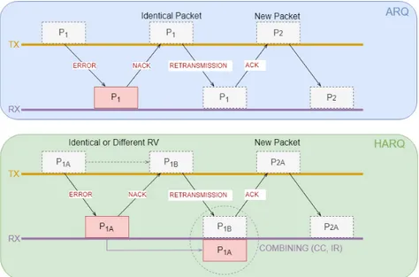
The reduced latency and high throughput of LTE is traceable to a number of mechanism implemented in it. The physical/MAC layer of LTE adopts two key techniques: Hybrid Automatic Repeat reQuest (HARQ) and Adaptive Modulation and Coding (AMC). These two techniques work together to give a very adaptive transport mechanism in LTE [10].
HARQ is a technique for both error detection and correction by identifying when transmission errors occur and facilitating re-transmission from the source thereby ensuring the reliably data transportation from one network node to an-other. Please be advised that LTE uses Type-II HARQ protocols. To handle re-transmission errors, LTE uses two loops. A fast HARQ inner loop to take care of most errors a robust selective-repeat ARQ outer loop to take care of residual errors.
adaptation is achieved using the AMC mechanism, with the aim of improving data throughput in a fading channel. AMC works by varying the downlink modulation technique depending on the channel conditions of each user. Given a good channel condition, the LTE system can use a higher order modulation scheme (64-QAM with 6 bits per symbol) or reduced channel coding, making the channel more spec-trally efficient and resulting in higher bit rates. As the channel become noisy due to signal fading or interference, the system selects a lower modulation technique (QPSK or 16-QAM with fewer bits per symbol) or stronger channel coding to obtain a signal more robust at the expense of the bit rate.
3.2.3 Radio Channel Bandwidth in LTE
LTE is not only able to operate in different frequency bands, but can be also im-plemented using different spectrum sizes. This feature make possible to harness the global wireless market and align with regional spectrum regulations.
LTE implements a scalable radio channel bandwidth from 1.4 to 20 MHz with a subcarrier spacing of 15 KHz. The 20 MHz bandwidth is required for optimum performance and to cope with the growth of the mobile internet. 3GPP has speci-fied the LTE air interface to be ”bandwidth agnostic” to allow the physical layer to adapt different spectrum allocation without severe impact on system operation.
3.2.4 LTE Technological Advancements
There are two groups of technological advancements on LTE Release 8, namely LTE Release 9 and LTE Release 10 [11].
Transmission Mode 8 (TM8) and Dual Layer Beamforming were added in LTE Release 9, that also focuses on following features enhancing the LTE Release 8 core network.
• Location, broadcast and IP Multimedia Subsystem (IMS) emergency services using GPRS and EPS;
• Support of circuit switching services over the LTE EPS;
• eNB considerations focusing on security, QoS, charging and access restric-tions;
The LTE Release 10 is an evolution of LTE to meet the IMT-A requirements defined by ITU. It is known as LTE-Advanced (LTE-A) and it focuses on higher capacity as following:
• Downlink peak data rate of 3 Gb/s and uplink peak data rate of 1.5 Gb/s; • Higher spectral efficiency on the downlink (e.g. 30 bps/Hz);
• Increased number of simultaneously active subscribers; • Improved performance at cell edges.
To achieve the above-mentioned feats, the three following new techniques are considered in LTE-A [12]:
• Carrier Aggregation (CA): The most basic way to increase capacity is add more bandwidth. LTE-A is increased in bandwidth by means of aggregation of up to five component carriers of different bandwidths to form a maximum bandwidth of 100 MHz. CA can be used in both FDD and TDD schemes. • Enhanced multiple antennas techniques: in LTE-A a ninth transmission
mode called Eight Layer Spatial Multiplexing (8 x 8 MIMO) and a second transmission mode (4 x 4 MIMO) are added to the downlink and uplink re-spectively.
• Relay Nodes (RN): Relay Nodes bring the possibility of efficient heteroge-neous network in LTE-A. The Relay Nodes are low power base stations that provide enhanced coverage and capacity at cell edges. By means of RN, con-nectivity without the need of optical fibres can be provided to remote areas. • Coordinated Multipoint (CoMP) Transmission/Reception: This feature was
fi-nalized in Release 11. In this technique, multiple transmit and receive points provide coordinated transmission/reception. This transmission/reception is carried put jointly and dynamically across multiple cell sites, same site or within same or different eNBs. The primary purpose of CoMP is to improve the performance at cell edge.
The on-going enhancements in Release 13 include additional features for allow-ing the LTE to operate in the unlicensed spectrum and the expansion of the CA framework to support more than five component carriers. Other enhancements in Release 13 include:
• Enhancements for Machine-Type Communications (MTC) defining a new low complexity UE type that supports reduced support for downlink transmission modes, reduced bandwidth, reduced transmit power and very long battery life to support the rise of Internet of Things (IoT) markets;
• Improving multi-user transmission techniques using superposition coding for increasing the LTE system spectral efficiency;
• Use of full dimension MIMO/Elevation Beamforming for improved spectral efficiency by the use of higher dimension MIMO of up to 64 antennas at the eNB and utilizing the vertical dimension for MIMO and beam-forming oper-ations.
• Improved indoor positioning accuracy and support for Single-cell Point-to-Multipoint (SC-PTM).
Table 3.1 gives a summary of the key characteristics of LTE at its inception and the current features of LTE as today, LTE-A.
Parameter LTE LTE-A
Frequency Band Country-dependent Country-dependent Downlink Peak Data Rate 100 - 326 Mbps 1 - 3 Gbps Uplink Peak Data Rate 50 - 86 Mbps 500 Mbps - 1.5 Gbps Channel Bandwidth (MHz) 1.4, 3, 5, 10, 15, 20 UP to 10 MHz Peak Spectral Efficiency 16 bps/Hz (DL) 30 bps/Hz (UL)
Latency 10 ms Less than 5 ms
Duplex Method FDD and TDD FDD and TDD
Multiplexing OFDM OFDM
Multiple Access Method OFDMA in DL SC-FDMA in UL OFDMA in DL SC-FDMA in UL Modulation Scheme QPSK 16-QAM 64-QAM QPSK 16-QAM 64-QAM Multiple Antenna Technique Up to 4 x 4 MIMO (DL) 8 x 8 MIMO in DL 4 x 4 MIMO in UL
3.2.5 Towards the 5G
The most obvious paths of evolution towards 5G radio access are improved spec-trum efficiency, network densification and specspec-trum extension. As stated in [13], currently deployed networks use 1-3 GHz frequency band which eventually fall short of meeting the multi-gigabit requirements of future communication services such as Ultra-High Definition Video (UHDV) [14]. The millimeter wave (mmWave) frequency band (from 30 to 300 GHz) offers huge bandwidth and consequently spectrum extension for mobile networks. mmWave communications particularly in the 28, 30, 60 GHz and E-band (71-76 and 81-86 GHz) bands will play a criti-cal role in 5G applications such as small cell access, cellular access and wireless backhaul. Some of the key radio access technologies that will pave the way for 5G mobile communications include:
• Further improvements to low power small cells to provide network densifica-tion;
• The use of massive MIMO and large number of miniaturized antennas at mmWave frequencies to provide significant increase in spectrum efficiency and user throughput;
• Use of access techniques such as Filtered OFDM and Sparse Code Multiple Access (SCMA) to improve system efficiency, support energy saving, reduced latency and massive connectivity;
• Use of more efficient coding schemes such as Polar codes, which can achieve Shannon capacity using simple encoder.
• Use network coding for interference management and for the security, throughput and robustness for routing information through the network im-provement;
• Use of Full Duplex to support bi-directional communications without the use of time or frequency duplex, to double the system capacity and reduce the latency;
• Use of self-organizing network operation for a cost effective management of the massive network densification.
The LTE technology has undergone a significant evolution from its first release, which was aimed at meeting the IMT-2000 requirements to achieving and even
exceeding the IMT-Advanced (4G) requirements. These technologies played a crit-ical role in the frequency spectrum below 6 GHz that has been allocated for mobile communication at the World Radio Conference (WRC) in 2015. However, for the spectrum band above 6 GHz which is expected to be allocated at WRC in 2019, a new radio access technology is necessary. Thus 5G is the next frontier of a broader ICT ecosystem that will enhance mobile internet and empower Internet-of-Things will be heterogeneous across frequency spectrum.
3.3 The 5G Next Generation Mobile Network
It is expected that mobile and wireless traffic volume will increase a thousand-fold over the next decade which will be driven by the expected 50 billion connected devices connected to the cloud by 2020 and all need to access and share data any-where and anytime.
With the rapid increase in the number of connected devices, some challenge appear which will be responded by increasing capacity and improving energy ef-ficiency, cost and spectrum utilization as well as providing better scalability for handling the increasing number of the connected devices. For the vision of all-communicating world relative to today’s network, the overall technical aim is to provide system idea that supports [15]:
• 1000 times increased data volume per area;
• 10 to 100 times increased number of connected devices; • 10 to 100 times increased typical data user data rate; • 10 times extend battery life;
• 5 times reduced end to end latency.
To meet such demands of the user and to overcome the challenge that has been put forward in the 5G system, a drastic change in strategy of designing the 5G wireless cellular architecture is needed. New novel concepts such as Software de-fined networking (SDN), Network functions virtualisation (NFV), Network slicing and functional split will have to be considered in the 5G system deployment.
Figure 3.2: Services in Future 5G Networks
3.3.1 5G Core Network Architecture
To use 5G to support a wide range of services with different demanding per-formance requirements, and to insert 5G into new industrial value chains, 5G requires a new system architecture and in particular a new core network known as Next-Generation Core (NG-Core). A ”cloud native” core will enable operators to achieve flexibility, scalability, reliability and performance needed to meet 5G service targets [16].
The NG-Core should support and enable the wide range of services envisioned for 5G across several market segment, as outlined in Fig. 3.2.
There are several principles that illustrate what 5G NG-Core will look like and can inform specification and development. These are the follows:
• Meet Demanding KPIs. Performance is critical to ensure availability, la-tency, reliability, user experienced data rates and area traffic capacity.
• Access Independent. The new core should support multiple access tech-nologies and key functions should be decoupled from access when possible and appropriate.
• Flexible, Scalable & Programmable. To adapt to change and support dynamic services using network slicing, the new core will sue cloud-native architectures and software technologies.
• Support Real-Time & Non-Real-Time Services. NG-Core should support highly-dynamic and variable services with appropriate quality of experience (QoE).
• Interwork with Existing Networks. This includes existing 4G core net-works, multiple non-3GPP access types, ad service-layer technologies such as IMS/VoLTE and IoT platforms.
Anyway, in the end, 5G needs a new, software-centric architecture designed to operate in a modern, cloud-native networking environment. This is true not only in principle, but also in terms of specific capabilities and services provided by the NG-Core. These include:
• Access Agnostic Core. The existing core is not access-independent. While non-3GPP access is supported by the LTE EPC, it requires integration of specific equipment to connect, for example, Wi-Fi into the mobile core. In NG-Core, mobility management may only be instantiated as needed; fixed access would only need a subset of the NG-Core features to operate. The addition of unlicensed radio will also generate new interworking requirements.
• Connectionless Services. 5G will move from the ”always-on” model in 4G to an ”always-available” model in which connectivity management is used as needed, for example, for session continuity or mobility. This is particularly important for IoT devices that, to save battery life, unscheduled uplink trans-missions on both the data and control plane to transmit data and signaling traffic.
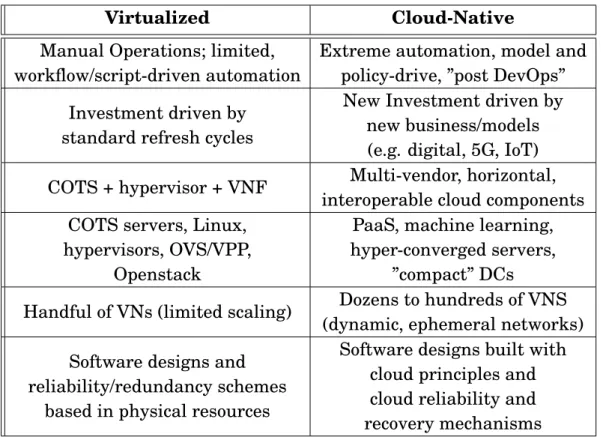
• Ultra-Low Latency & Mission-Critical Services. Some advanced 5G ser-vices, such as tactile Internet and industrial control systems, require ultra-low latency. This will generate a new architecture that limits the physical distance between access and core and makes use of distributed forwarding elements. A new session and service continuity model, as well as a new QoS model, that efficiently enables guaranteed services will also be needed. The Cost and performance of a Web-scale infrastructure has inspired operators to apply cloud principles to their own networks: commercial-off-the-shelf (COST) hardware, distributed processing, centralized control, model-driven configuration, automation, etc., now inform the evolution of operator networks. Table 3.2 com-pares some high-level differences between virtualized networks and cloud-native
native networks. Given the timeline and the nature of 5G services, NG-Core will be designated for, and deployed on, cloud infrastructure.
Virtualized Cloud-Native
Manual Operations; limited, workflow/script-driven automation
Extreme automation, model and policy-drive, ”post DevOps” Investment driven by
standard refresh cycles
New Investment driven by new business/models (e.g. digital, 5G, IoT) COTS + hypervisor + VNF Multi-vendor, horizontal,
interoperable cloud components COTS servers, Linux,
hypervisors, OVS/VPP, Openstack
PaaS, machine learning, hyper-converged servers,
”compact” DCs
Handful of VNs (limited scaling) Dozens to hundreds of VNS (dynamic, ephemeral networks) Software designs and
reliability/redundancy schemes based in physical resources
Software designs built with cloud principles and cloud reliability and recovery mechanisms
Table 3.2: Virtualized vs. Cloud-native Networks
The 5G functional architecture, including the NG core itself, is now under de-velopment in 3GPP Release 15. This specification work is fundamental to how the 5G NG-Core will be designed and then deployed and operated in commercial net-works. The specification work covers both non-standalone (NSA) mode, in which the 5G radio is integrated with LTE, and standalone (SA) mode, which enables 5G radio to be deployed using NG core without any LTE dependencies.
The two proposed architecture are shown in Fig. 3.3 and 3.4 respectively. The first one is a point-to-point architecture, (see Fig. 3.3), that can be thought of as a traditional 3GPP architecture. It splits control- and user-plane and sepa-rates access and mobility management (AMF) and session management (SMF) to enable independent evolution and scaling. On the access side, it minimizes core network dependencies by specifying common interfaces for 3GPP and non-3GPP access types. In the user-plane, it enables advanced features, such as User plane Function (UPF) branching, if the service requires. In short, it is familiar, yet also novel enough, to meet the needs of 5G in the near-term, and is flexible enough to evolve over time. One challenge with this model is that a change in topology occurs when a new function is added, and this requires new interfaces to be
es-Figure 3.3: Point-to-Point NG-Core Architecture
tablished between neighboring functions. Since the service consumption is tied to the network function, this is one of the main factors that makes mobile core net-works relatively difficult to change and adapt. NG core should be virtualized and cloud-based to make changes of this kind faster and easier. Because the Point-to-Point NG core architecture is essentially nodal, it is easily imaginable that the functional elements belonging to it will be developed as discrete pieces of equip-ment or as discrete VNFs. A truly cloud-native model would probably lean toward a network function as-a-service model.
The second proposed architecture defined as a Service Based Architecture (SBA), shown in Fig. 3.4, is, arguably, more aligned with modern cloud principles. The functional elements are the same of the Point-to-Point NG-Core architecture and also the N1, N2, N3, N4 interfaces to the control-plane are unchanged. The dif-ference is that rather then having predefined interfaces between the control-plane nodes, the functions themselves present ”service interfaces” (APIs) to each other on an on-demands basis. The NF Repository Function (NRF) provides registra-tion and discovery mechanisms to enable the different control-plane components to communicate directly. The service-based NG-Core architecture reflects the idea of a Network Cloud OS, where network services are composed using a library of functions hosted in the cloud and chained together to create the end-to-end service. The challenge is actually implementing this model, as it relies on the availability and maturity of cloud networking technologies outside the 3GPP domain. Indeed, for example, resource and service orchestrators needed to enable this are part of the NFV cloud platform environment that NG-Core will be deployed in.
Figure 3.4: Service-Based NG-Core Architecture
two different ways of representing a common set of functional elements. It is possi-ble, perhaps likely even, that operators will start with a point-to-point architecture and then migrate to a service-based architecture over time.
The main functional elements of the above proposed NG architectures are briefly described in the following:
• AUthentication Function (AUSF): keeps a key for reuse, derived after au-thentication, in case of simultaneous registration of a UE in different access network technologies, i.e. 3GPP access networks and non-3GPP access net-works such as IEEE 802.11 Wireless Local Area Network (WLAN).
• Access and Mobility Management Function (AMF): a control-plane compo-nent that manages access control and mobility. It handles all the 5G signal-ing comsignal-ing from and gosignal-ing to the UE, supports user access to the network and manages mobility by interacting with the UE and with other NFs (e.g., SMF, AUSF, etc.). The AMF will likely also include network slice selection functionality. The AMF contains part of the LTE MME functionality.
• Session Management Function (SMF): is the control part of a PDU session. That is, it configures NG tunnels, allocates IP addresses with DHCP, and configures traffic steering (e.g., towards a third party or an edge cloud). The SMF contains parts of the LTE MME and P-GW.
• User Plane Function (UPF): it handles the NG user plane (NG-U) tunnel forwarding and the related data path services, such as anchoring for han-dover, QoS, and traffic policy enforcement. The UPF contains parts of the LTE SGW and PGW functionalities. Multiple different UPFs, in distributed and centralized locations, can be used by operators, according to the services type.
• Policy Control Function (PCF): provides a common policy framework incor-porating network slicing, roaming and mobility management to other control plane functions, such as SMF.
• Unified Data Management (UDM): component used for storage the sub-scribers data and profiles (i.e. credentials, identifiers, AMF details, and SMF assignments) for the current session. The underlying idea of the UDM is to create a central database for UE configuration information, so that the NFs can be designed as stateless services, improving architectural agility The UDM contains part of the LTE HSS functionality.
• NR Repository Function (NRF): this is a new functionality without equiv-alent in LTE and it is present only in the service-based architecture. It provides registration and discovery functionality so that network functions (NFs) can discover each other and communicate directly. When it receives an NF discovery request from a NF instance, it provides the discovered NF instances.
• Application function (AF): resembles an application server that can interact with the other control-plane NFs. AFs can exist for different application ser-vices, and can be owned by the network operator or by trusted third parties. For instance, the AF of an over-the-top application provider can influence routing, steering its traffic towards its external edge servers.
• Network Exposure Function (NEF): exposes the capabilities of networks and network/UE events for third-party, application function, edge computing, and other purposes. It is not present in LTE and it is implemented only in the service-based architecture.
• Data Network (DN): stands for e.g. operator services, Internet access or 3rd party services.