Inserire logo o denominazione del cobeneficiario
Report sulla progettazione di prove di
irraggiamento con ioni pesanti di coating
realizzati mediante ablazione laser
F. Garcia Ferré, M. Beghi, F. Di Fonzo
Report RdS/2013/039
Agenzia nazionale per le nuove tecnologie,
REPORT SULLA PROGETTAZIONE DI PROVE DI IRRAGGIAMENTO CON IONI PESANTI DI COATING REALIZZATI MEDIANTE ABLAZIONE LASER
F. Garcia Ferré, M. Beghi, F. Di Fonzo (POLIMI)
Settembre 2013
Report Ricerca di Sistema Elettrico
Accordo di Programma Ministero dello Sviluppo Economico -‐ ENEA Piano Annuale di Realizzazione 2012
Area: Produzione di energia elettrica e protezione dell'ambiente
Progetto: Sviluppo competenze scientifiche nel campo della sicurezza nucleare e collaborazione ai programmi internazionali per il nucleare di IV Generazione
Obiettivo: Sviluppo competenze scientifiche nel campo della sicurezza nucleare Responsabile del Progetto: Mariano Tarantino, ENEA
Il presente documento descrive le attività di ricerca svolte all’interno dell’Accordo di collaborazione “Sviluppo competenze scientifiche nel campo della sicurezza nucleare e collaborazione ai programmi internazionali per il nucleare di IV generazione” Responsabile scientifico ENEA: Mariano Tarantino
Sigla di identificazione Distrib. Pago E.I\Eb.. Ricerca Sistema Elettrico. ADPFISS - LP2 - 015 L 1 Titolo
Report sulla progettazione di prove di irraggiamento con ioni pesanti di coating realizzati mediante ablazione laser
Ente emittente POLIMI (IIT)
PAGINA
DI G
UARDIA
Descrittori
Tipologia del documento: Collocazione contrattuale:
Rapporto Tecnico
Accordo di programma ENEA-MSE su sicurezza nucleare e reattori di IV generazione
Tecnologie dei Materiali
Caratterizzazione dei Materiali
Generation IV reactors
Argomenti trattati:
Sommario
Viene descritta la progettazione di prove di irraggiamento con ioni pesanti di rivestimenti di
allumina prodotti per ablazione laser da eseguire presso la piattaforma sperimentale JANNUS dei
centri di ricerca CEA di Saclay (SRMP) e di Orsay (CSNSM). In confronto all'utilizzo di neutroni, gli ioni pesanti hanno il vantaggio di permettere il raggiungimento di un danno da irraggiamento elevato in tempi brevi ed a bassi costi, il tutto senza attivare i campioni irraggiati, il che facilita la loro successiva caratterizzazione. I campioni irraggiati verranno caratterizzati con prove di nanoindentazione, scratch e spettroscopia Brillouin, per valutarne le proprietà meccaniche. I campioni verranno inoltre caratterizzati dal punto di vista della microstruttura tramite analisi XRD,
SEM, spettroscopia Raman e TEM ex-situo Per seguire l'evoluzione della struttura durante
l'irraggiamento verranno eseguite osservazioni TEM in situ durante gli esperimenti di irraggiamento.
Note
Rapporto emesso da POLIMI (IIT) Autori:
F. Garcia Ferré, M. Seghi, F. Di Fonzo (POLlMI)
Copia n. In carico a: NOME NOME 2 FIRMA NOME 1 FIRMA
o
EMISSIONEM (ssimo ~ngiWini NA Maria4oJf~tino
18/09/2013 f---t---.ìl-l---+----'+-+---+---+-I----J.-/---l
/
1
-
Au
l
,
l.
A/
W;'
FIRMA
CONVA~DA
DESCRIZIONE DATA VISTO APPROVAZIONE
REV.
CIRTEN
Consorzio Interuniversitario per la Ricerca TEcnologica Nucleare
Lavoro svolto in esecuzione dell’Attività LP2. B1
AdP MSE-ENEA sulla Ricerca di Sistema Elettrico - Piano Annuale di Realizzazione 2012 Progetto B.3.1 “Sviluppo competenze scientifiche nel campo della sicurezza nucleare e collaborazione ai
programmi internazionali per il nucleare di IV generazione
UNIVERSITA’
POLITECNICO DI MILANO
Progettazione di prove di irraggiamento con ioni pesanti di
coating realizzati mediante ablazione laser
Autori
F. García Ferré, M. Beghi, F. Di Fonzo (POLIMI)
B.1 Qualifica coating e materiali strutturali per sistemi LFR
REPORT
“LP2.b.1_c Report sulla progettazione di prove di irraggiamento con ioni pesanti di coating realizzati mediante ablazione laser”
Rif. Documento: IIT_2 Data: 16-09-2013
2
Sommario
1. Introduzione ... 3
2. Progettazione delle prove di irraggiamento ... 4
3. Simbologia ... 6
4. Bibliografia ... 7
3
1. Introduzione
L’obiettivo di questo task è la qualifica preliminare dei coating di allumina prodotti tramite PLD mediante prove di irraggiamento con ioni pesanti presso la piattaforma sperimentale JANNUS dei centri di ricerca CEA di Saclay (SRMP) e di Orsay (CSNSM). In confronto all’utilizzo di neutroni, gli ioni pesanti hanno il vantaggio di permettere il raggiungimento di un danno da irraggiamento elevato in tempi brevi ed a bassi costi, il tutto senza attivare i campioni irraggiati, il che facilita la loro successiva caratterizzazione.
Per accedere alla piattaforma sperimentale JANNUS, è stato necessario presentare un progetto di ricerca all’istituzione francese EMIR, la quale raduna diverse piattaforme sperimentali per l’irraggiamento di materiali con ioni pesanti. La scadenza per la presentazione dei progetti è tipicamente a Novembre di ogni anno. Il progetto viene valutato da una commissione scientifica, la quale attribuisce tempo macchina ai progetti in base al merito scientifico, per un massimo di 5 giorni lavorativi. Ulteriori informazioni sono disponibili sul sito internet: http://emir.in2p3.fr/.
Il progetto di irraggiamento presentato ha ricevuto una valutazione positiva dalla commissione scientifica, la quale ha stabilito che gli irraggiamenti si svolgeranno presso il centro CEA di Saclay a Novembre del 2013, e presso il centro CEA di Orsay presumibilmente a Febbraio del 2014, e comunque entro Aprile 2014. Il tempo messo a disposizione è di 5 giorni in entrambi i casi.
Nel presente report viene illustrato il progetto di irraggiamento presentato alla commissione scientifica di EMIR.
4
2. Progettazione delle prove di irraggiamento
Il titolo del progetto presentato a EMIR è: “Structural and mechanical stability of an advanced Al2O3
nanocomposite coating under ion irradiation up to high dpa”. L’obiettivo principale della proposta è quello di raggiungere i 100 dpa (displacement per atom) a 600 °C nei coating considerati, dato che per i reattori al Pb si prevede una dose di irraggiamento attorno a questi valori ed a tale temperatura. In particolare, è stato richiesto l’accesso a due diverse piattaforme sperimentali, per 5 giorni ciascuna: il centro di Saclay (che permette di raggiungere la dose richiesta nel tempo massimo messo a disposizione da EMIR), ed il centro di Orsay (che permette di studiare l’evoluzione della struttura dei campioni in situ, tramite TEM durante l’irraggiamento).
I campioni irraggiati nel SRMP serviranno a valutare le variazioni delle caratteristiche meccaniche dei rivestimenti tramite prove di nanoindentazione, scratch e spettroscopia Brillouin, da effettuare in seguito all’irraggiamento. Allo stesso modo, l’evoluzione strutturale sarà studiata tramite XRD, SEM, spettroscopia Raman e TEM ex-situ. Come già spiegato, l’evoluzione della struttura durante l’irraggiamento sarà studiate tramite TEM in situ presso il centro CSNSM.
In entrambi i casi, in modo tale da massimizzare il rateo di dose, sono stati scelti gli ioni Au3+ sotto proposta degli stessi responsabili dei centri. Infatti, come sottolineato in [1], gli ioni pesanti sono in grado di massimizzare il danno da irraggiamento per unità di percorso nei materiali ceramici isolanti. Inoltre, l’utilizzo di questo tipo di ioni permette di mantenere un rapporto ENSP (Electronic to Nuclear Stopping Power) molto basso, compreso tra 1 e 5. Questo fatto è importante, perché nei reattori di quarta generazione si prevede un valore attorno a 4 [1]. In pratica, l’ENSP dà una misura dell’importanza relativa dell’energia che gli ioni incidenti perdono riscaldando il materiale, rispetto a quella che perdono in collisioni con altri nuclei (cioè quella frazione dell’energia che genera, di fatto, i dpa). Altri tipi di ioni, in particolare gli ioni leggeri, generano rapporti ENSP molto superiori, oltre 1000. Perciò, il danno da loro causato nel materiale non è rappresentativo del tipo di danno che si avrebbe in reattore. Gli ioni oro hanno anche il vantaggio di non introdurre cambiamenti chimici nel materiale in seguito all’impiantazione.
Attraverso calcoli SRIM (software gratuito disponibile online) effettuati dal personale del centro SRMP, è stato possibile valutare che per raggiungere almeno i 100 dpa nell’allumina con ioni oro (in corrispondenza del picco di rilascio di energia) è necessaria una fluenza di 3,65.1016 ioni/cm2. Questa fluenza può essere raggiunta in circa 25-30 ore con un flusso di ioni minimo di 4.1011 ioni/cm2s, o in circa 50-60 ore con un flusso di ioni minimo di 2.1011 ioni/cm2s. Il flusso raggiunto e la durata dei catodi nei laboratori CSNSM e SRMP non è noto a priori. Pertanto, si è scelto un flusso minimo più basso (2.1011 ioni/cm2s) per i laboratori CSNSM, dove probabilmente è più difficile raggiungere flussi più elevati, ed un flusso più alto per i laboratori SRMP (4.1011 ioni/cm2s). Questi flussi consentono in ogni caso di raggiungere il danno richiesto entro i 5 giorni lavorativi messi a disposizione, tenendo conto dei tempi necessari a mettere a punto il sistema, portarlo in temperatura e riportarlo a temperatura ambiente. Inoltre, nel caso dei laboratori
5 SRMP, il flusso maggiore consente anche di sdoppiare l’irraggiamento in due periodi di 25 ore per poter cambiare il catodo, qualora fosse necessario.
L’energia degli ioni proposta per l’osservazione TEM in situ al CSNSM è 4 MeV, il che garantisce una profondità di penetrazione degli ioni di 500 nm (da calcoli SRIM). In ogni caso, il valore finale utilizzato potrà subire delle variazioni. Infatti, i campioni per l’osservazione TEM in situ dovranno essere spessi al massimo 100 nm per permettere la trasmissione degli elettroni. Perciò, è possibile che l’energia degli ioni venga ridotta, in modo da ridurre la profondità di penetrazione degli stessi, per massimizzare il rilascio di energia nello spessore del campione osservato. Per l’SRMP, l’energia proposta è 8 MeV, in modo tale da rilasciare la massima quantità di energia a circa 1 micron di profondità (sempre da calcoli SRIM). Fabbricando coating dello spessore di 1 micron, quindi, il massimo danno da irraggiamento sarà rilasciato sull’interfaccia col substrato, la quale potrà essere testata con prove di scratch. Fabbricando coating più spessi, il danno sarà rilasciato nel volume del materiale, permettendo alle misure di nanoindentazione di rilevare cambiamenti delle proprietà meccaniche relativamente al bulk del materiale di rivestimento. Infine, per quanto riguarda la preparazione dei campioni, per i laboratori del CSNSM, si prevede di depositare i coating direttamente su delle griglie TEM standard col supporto per la crescita di film. Il personale del laboratorio raccomanda l’utilizzo di un supporto in Si3N4, noto per la stabilità sotto irraggiamento ed in temperatura. Per i laboratori SRMP, invece, è stato progettato un supporto in grado di alloggiare 4 piattine di 1,5 cm di larghezza, per 3 cm di lunghezza ed 1 mm di spessore. I disegni del supporto sono stati forniti direttamente dal laboratorio CEA SRMP (vedere allegato 1).
6
3. Simbologia
JANNUS: Joint Accelerators for Nano science and Nuclear Simulation CEA: Commissariat à l’énergie atomique et aux énergies alternatives SRMP: Service de Recherches en Métallurgie Physique
CSNSM: Centre de Sciences Nucléaires et de Sciences de la Matière
EMIR: Réseau national d’accélérateurs pour les Etudes des Matériaux sous IRradiation dpa: displacement per atom
TEM: Transmission Electron Microscopy XRD: X-Ray Diffraction
SEM: Scanning Electron Microscopy
ENSP: Electronic to Nuclear Stopping Power SRIM: Stopping and Range of Ions in Matter
7
4. Bibliografia
8
5. Elenco degli allegati
Allegato 1. Disegni del supporto campioni per le prove di irraggiamento presso il centro CEA SRMP. Allegato 2. Progetto di irraggiamento presentato alla commissione scientifica EMIR.
0.50 X 45° 1.50 0.50 X 45° 4 4 3 3 5 10
Echantillon
ANGULAIRES: A4 BORDAS Eric MASSE: ANGLES VIFS FEUILLE 1 SUR 1 ECHELLE:2:1 No. DE PLAN TITRE: REVISION NE PAS CHANGER L'ECHELLEMATERIAU: DATE
SIGNATURE NOM
CASSER LES SAUF INDICATION CONTRAIRE:
LES COTES SONT EN MILLIMETRES ETAT DE SURFACE: TOLERANCES: LINEAIRES: AUTEUR 0.50 X 45° 0.50 X 45°
19° 26° ANGLES VIFS CASSER LES NOM ANGULAIRES:
Platine_3F
BORDAS Eric MASSE: A4 FEUILLE 1 SUR 1 ECHELLE:1:1 No. DE PLAN TITRE: REVISION NE PAS CHANGER L'ECHELLEMATERIAU: DATE
SIGNATURE SAUF INDICATION CONTRAIRE: LES COTES SONT EN MILLIMETRES ETAT DE SURFACE: TOLERANCES: LINEAIRES: AUTEUR 5.5 0 3.20 60° 1 .1 0 2 0 M 2.2 0x 0.4 5 A A COUPE A-A 0.50 X 45° 0.25 X 45° 5 3 .8 0 6 6 0.50 X 45° 0.25 X 45° 4 4 9 5 R 1 R0.25
48 .50 ° 20 19° CASSER LES ANGLES VIFS ANGULAIRES:
Bague
BORDAS Eric MASSE: A4 FEUILLE 1 SUR 1 ECHELLE:2:1 No. DE PLAN TITRE: REVISION NE PAS CHANGER L'ECHELLEMATERIAU: DATE
SIGNATURE NOM
SAUF INDICATION CONTRAIRE: LES COTES SONT EN MILLIMETRES ETAT DE SURFACE: TOLERANCES: LINEAIRES: AUTEUR COUPE A-A 1.50 X 45° 2 3 3 0.50 X 45° 2 0 .2 0 1 2 .2 0 34 1.10 5 2 3 4 1 .10 A A
7 .9 0 5 M2 CASSER LES ANGLES VIFS ANGULAIRES: A4 BORDAS Eric MASSE:
Vis & Rondelle
FEUILLE 1 SUR 1 ECHELLE:5:1
No. DE PLAN TITRE:
REVISION NE PAS CHANGER L'ECHELLE
MATERIAU: DATE
SIGNATURE NOM
SAUF INDICATION CONTRAIRE: LES COTES SONT EN MILLIMETRES ETAT DE SURFACE: TOLERANCES: LINEAIRES: AUTEUR 5 2.5 0 0.50
1
P
ROPOSAL FOR AN EXPERIMENT AT
EMIR
R
ESEAU
N
ATIONAL D
’
ACCELERATEURS POUR LES
E
TUDES DE
M
ATERIAUX SOUS
I
RRADIATION
Beam time period: April 2013, March 2014
Deadline for submission
:
November 23
th, 2012
*All the fields marked with a star are required.
Proposal Title
*
:
S
TRUCTURAL AND MECHANICAL STABILITY OF AN ADVANCEDA
L2O
3NANOCOMPOSITE COATING UNDER ION IRRADIATION UP TO HIGH DPA
Spokesperson*:Fabio Di Fonzo
Before filling the next points, seehttp://emir.in2p3.fr
Check below the requested EMIR sites (one form by project even if the request is for multiple sites) and the number of days requested or time units (UT) for CIMAP, for each site *:
Check sites
involved Number of days or UTs requested
CEMHTI CIMAP CSNSM X 5 LSI SRMA SRMP X 5
2
Does this experiment benefit from an industrial grant? NO: X YES:
Which one? :
Does this experiment benefit from another grant (ANR, NEEDS,
Europe…)? NO: X YES:
Which one? : This project forms part of a research collaboration between Istituto Italiano di Tecnolgia (IIT), Politecnico di Milano and the Italian Agency ENEA (Agenzia Nazionale per le Nuove Tecnologie,
l’Energia e lo Sviluppo Economico Sostenibile)
Deputy Spokesperson*: Francisco Garcia Ferré
Phone*:+390223999897 Fax:
E-mail:*[email protected]
Address:*
Center for Nano Science & Techology – Istituto Italiano di Tecnologia Via G. Pascoli 70/3
20133 Milano (MI) Italia
List of the participants with complete address:
Name Laboratory
Francisco Garcia Ferré
Pulsed Laser Deposition Lab
Center for Nano Science & Technology – Istituto Italiano di Tecnologia
Via G. Pascoli 70/3 20133 Milano (MI) Italia
Marco Beghi
Micro- and Nano-structured Materials Lab Department of Energy – Politecnico di Milano Via Ponzio 34/3
20133 Milano (MI) Italia
Fabio Di Fonzo
Pulsed Laser Deposition Lab
Center for Nano Science & Technology – Istituto Italiano di Tecnologia Via G. Pascoli 70/3 20133 Milano (MI) Italia Odile Kaitasov CSNSM Bâtiment 108 91405 Orsay Campus France
3
Check below if you are applying for:
Refunding of accommodation costs: Refunding of travelling costs (only in France):
1) All publications containing results from experiments performed at EMIR should mention the Emir Network, and for projects performed in collaboration with local contacts, publications should include these local contacts as co-authors.
4
Materials under Irradiation at CSNSM
(O
RSAY
)
*All the fields marked with a star are required.
*
Choose below the facilities to be used
*
(See http://emir.in2p3.fr/Equipment-description,43 ):
JANNuS (ARAMIS + TEM):
XJANNuS (IRMA + TEM):
JANNuS (ARAMIS + IRMA + TEM):
ARAMIS + on line instrumentation:
ARAMIS + IRMA:
The submission of this proposal implies that you certify that the given information is true and complete. You accept to include the following sentence in your publications on the results obtained at JANNUS: “experiment done at JANNUS (Joint Accelerators for Nanoscience and Nuclear Simulation), Orsay, France”, and supported by the French Network EMIR » and for projects performed in collaboration with local contacts, publications should include these local contacts as co-authors.
At JANNuS-ORSAY, each experiment with the TEM
requires the presence of an experienced
microscopist, presence which must be planned by the
proposing researcher.
5
CSNSM: ARAMIS + TEM (JANNuS - Orsay)
Required beam (Ion energy : 0.5 – 15 MeV) ; Seehttp://jannus.in2p3.fr/spip.php?rubrique16
Ions
*
Energy*
MeV Fluence (ions/cm²)*
Fluxmin*
(ions/(cm2.s)) Temperature*
Au 4 2,4.1016 2. 1011 600 °CTotal number of days requested (from 2 to 5) : 5
Indicate the holder
*
Double tilt holder RT: Single tilt holder RT: Tilt rotation holder RT:
Double tilt heating holder: X N2 Double tilt holder:
*
Experimental Procedure:(Estimation of time for irradiation/implantation, time for characterisation, type of experiments: one run (Dynamic observation) or number of steps…)The net irradiation time will be roughly 33 hours, plus around 1h 30min for characterization at each observation. In this experiment, one sample (appropriately prepared by the user) will be observed. In order to limit shadowing effects due to the GATAN heating double tilt holder, the irradiation of the sample will be performed in a sequenced mode. During irradiation the sample will be tilted normally to the ion line; then, at given steps (corresponding to doses of roughly 25, 50, 75 and 100 dpa close to the Bragg peak), samples will be tilted normally to the electron beam for HR-TEM characterization. EDX is required for elemental analysis, as well as EELS, in order to detect any variation or effect on the bonding/structure of the Al2O3 coating due to the irradiation with Au ions. The bottom mount camera
can provide useful information through contrast, since the sample is an insulator.
Laboratory equipments necessary during the scheduled time:
Wide angle camera : Video recorder: EFTEM: X
Bottom mount camera: X GIF: EDX: X
Films : STEM:
What date will you be ready to run? 2 : April 2013
Excluded periods 2 : 20 Dec 2013 – 15 Jan 2014
The submission of this proposal implies that you certify that the given information is true and complete. You accept to include the following sentence in your publications on the results obtained at JANNUS: “experiment done at JANNUS (Joint Accelerators for Nanoscience and Nuclear Simulation), Orsay, France”, and supported by the French Network EMIR ». For projects performed in collaboration with local contacts, publications should include these local contacts as co-authors.
2
The date of experiment will be sent to you after acceptance of your proposal, taking into account the excluded periods and the dates you will be ready to run.
6
SRMP: Triple beam facility (JANNuS - Saclay)
Required beams: Seehttp://emir.in2p3.fr/Equipment-description
Ions
*
Energy*
MeV Current min (nAe) Fux*
min (ions/(cm2.s)) Dose*
(ions/cm2) Au 8 4.1011 3,65.1016Splitting the beam time in several periods: NO: YES: X Minimum time per period : Two periods
of around 20-25 hours
Total number of days requested (½ to 5): 5
Samples: (Material, size, shape):
*
austenitic steel plates (width:10 mm; length: 33 mm; thickness: 1,5mm), coated with an engineered Al2O3 nanocomposite barrier
Total number of samples:
*
4 Possibility to irradiate several samples simultaneously (samples / run): Yes, 4samples
Experiment chamber:
Triple (or dual) beam: X IBA (only if combined with irradiation):
Single beam irradiation : User provided (enclose description):
Specific requirements for data acquisition:
Visible and IR cameras required to monitor any possible loss of structural integrity of the ceramic coatings.
Experimental conditions:
*
Without on-line characterisation measurements
Heating-cooling sample holder: X Room temperature: High temperature T = 600 °C
IBA sample holder: Liquid N2 temperature:
Vacuum level requested: 1,3.10-5 Pa
Time required to set-up:1 hour for sample mounting + 1 night for vacuum pumping Time required to dismantle the experiment:1 night + a couple of hours the following day
Laboratory equipment necessary during the scheduled time:
On-line IBA:
Other: 2 Thermocouples
7
Excluded periods: 20 Dec 2013 – 15 Jan 2014
JANNuS-SACLAY: Particular requirements: ion beam and experimental conditions, dimension
of the investigated samples (~½ page)
Include complementary precisions about experimental conditions (estimation of time for irradiation, time for characterisation, surface to be irradiated, energy degraders, thermal treatment, etc)
There are no special requirements for this experiment; the surface of the samples is smooth. In addition, the user will provide a suitable sample holder. The requested time is 5 days, which include the optimization of the experimental setup. The net irradiation time will be around 25 hours, if the requested flux is attained. If the maximum attainable flux were lower than the one requested, the irradiation time to reach 100 dpa would be higher. In any case, it will be possible to split the irradiation in two periods, if necessary, in order to be able to change the cathods. No energy degraders are needed.
The submission of this proposal implies that you certify that the given information is true and complete. You accept to include the following sentence in your publications on the results obtained at JANNuS: “experiment done at JANNuS (Joint Accelerators for Nanoscience and Nuclear Simulation), Saclay, France and supported by the French Network EMIR”. For projects performed in collaboration with local contacts, publications should include these local contacts as co-authors.
8
PROPOSAL STATEMENTS
*
To be filled only once, even if you plan to use several instruments
*
Context and motivations of the scientific project: (~½ page)*
Heavy liquid metals (HLM), such as Lead, Lead-Bismuth Eutectic (LBE) or Lead-Lithium Eutectic (LLE), have been selected as candidate materials for use as coolant and breeder blanket in advanced nuclear reactors and fusion systems [1-5]. Currently, the scientific community is strongly committed to the development of the HLM technology: for instance, the LEADER European Project deals with the design of a demo facility, namely the Advanced Lead-cooled Fast Reactor European Demonstrator (ALFRED), and of a full scale prototype, the European Lead Fast Reactor (ELFR). Other HLM-cooled facilities are also being pursued, including the Belgian MYRRHA (Multi-purpose hYbrid Research Reactor for High-tech Applications), or the Swedish ELECTRA (European LEad Cooled TRAining reactor), not to mention the ITER project, among others.
One of the key limitations of design and application of the HLM technology regards the ability of structural steels to withstand erosion degradation and corrosion phenomena at high temperature (above 500°C). For the time being, ceramic coatings seem to be the most reliable protection method. Among many options, alumina stands as a promising material, owing to its hardness and resistance to wear, strong chemical inertia, phase stability at high temperature and compatibility with oxidizing environments. Specific requirements include full compactness and density, strong interfacial bonding, wear resistance and mechanical compatibility with steels. Pulsed Laser Deposition (PLD) is a physical vapor deposition method for growing thin films that offers valuable means for fulfilling such requirements altogether, namely by engineering the properties of materials at the nano-scale length in a room temperature process.
The Istituto Italiano di Tecnologia (IIT) and the Politecnico di Milano are currently involved in the fabrication of advanced Al2O3 coatings by PLD for use in HLM-cooled nuclear systems, and in their
testing in collaboration with the Italian Agency ENEA (Agenzia Nazionale per le Nuove Tecnologie,
l’Energia e lo Sviluppo Economico Sostenibile). An extensive characterization campaign has shown that
PLD-grown Al2O3 is a suitable material for protecting steels in HLM environment. Some of the main
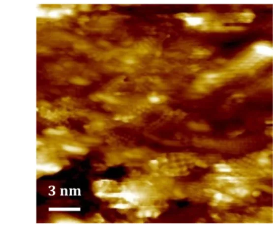
features of this material are an ensemble of metal-like mechanical properties (E=195±9 GPa, ν=0,29±0,02) and enhanced plastic behavior, full compactness and strong adhesion, as well as a relatively high hardness (H=10 GPa) [6,7]. These features are due to the nanostructure of the coatings (figure 1), which comprises a homogeneous dispersion of ultra-fine nanocrystalline domains (2-5 nm) in an amorphous alumina matrix.
The Al2O3 barriers have already been tested for protecting T91 steel plates at 600°C in stagnant HLMs
with outstanding results after 500 hours (figure 2) [8]. Long-term (>10.000 hours) tests in flowing Lead and thermal creep experiments are under way on coated austenitic tube and plate samples. Nevertheless, apart from corrosion and thermal creep, other issues still need to be addressed, among which, most importantly, resistance to irradiation (including irradiation creep, stability of the nanostructure and changes in mechanical properties and adhesion strength, among others).
9
*
Project description: objectives and new aspects (one page plus references and figures)*
Ion irradiation is a convenient way for simulating the effects of high-dose neutron damage in nuclear reactor components. The main goal of the project is to study the effects of ion irradiation on PLD-grown Al2O3 coatings in terms of morphological and structural features, as well as mechanical performance,
approaching high displacement per atom (dpa). The irradiation conditions are chosen to be as close as possible to the foreseen operation conditions for fuel cladding materials in Lead Fast Reactors (600°C and ≈ 100 dpa with a low Electronic to Nuclear Stopping Power ratio, namely lower than 10).
A large number of neutron irradiation experiments on several kinds of bulk alumina ceramics and single crystals have examined swelling, mechanical properties and microstructure after relatively low doses [9,10] and high doses [11,12]. Concerning irradiation with ions, as an example, a review of the effect of the irradiation spectrum on the microstructural evolution of bulk crystalline ceramic insulators is provided by S.J. Zinkle [13]. On the other hand, very little information is available concerning alumina coatings. For instance, J. Megusar [14] studied the structural stability of a 300 µm plasma-sprayed alumina coating after irradiation with fast neutrons (E>0,1 MeV) at low temperature (4,2 K) and low fluence (1,8.1022 n/m2). Obviously, the performance of alumina coatings under neutron or ion irradiation may differ conspicuously if compared to that of bulk crystalline samples of the same material, since the as-deposited structural features are different. Moreover, for thin films, the microstructure may change drastically for different deposition methods and process conditions.
As far as PLD-grown Al2O3 coatings are concerned, there is no reported study on their behavior under
irradiation. Anyhow, most encouraging results from a recent work on the stability of nano-oxide particles in Oxide Dispersion Strengthened (ODS) steels [15] have shown that 5 nm Y-Ti-O nanoclusters are stable after irradiation at 500°C by Fe ions up to 45 dpa. If this were also the case for the nanostructure of the PLD-grown Al2O3 coatings, the outstanding mechanical performance (which is due to the nanostructure)
might as well be conserved in-service throughout the lifetime of the component. The present study aims at exploring such possibility.
Following the main goal of the project, pre- and post-irradiation morphological and structrual analyses will be performed by Scanning Electron Microscopy (SEM), Transmission Electron Microscopy (TEM), X-Ray Diffraction (XRD) and Raman Spectroscopy, while the mechanical performance pre- and post-irradiation will be examined by Nanoindentation, Brillouin Spectroscopy and Nanoscratch. More specifically, the structural analyses are meant to assess the stability of the nanostructure of the coatings (nanocrystalline domains growth/amorphization, phase changes, shape modification, creation of point defects, amorphous matrix-nanocluster interface evolution), whereas the investigation of the mechanical properties (Young’s modulus, Poisson’s ratio, Hardness) and adhesive strength will give an insight to the effect of irradiation from an engineering point of view. These characterizations will be performed at the facilities of the Istituto Italiano di Tecnologia and the Politecnico di Milano. On the other hand, the in-situ TEM study at CSNSM will give an important contribution for gaining an understanding of the basic mechanisms that are involved in the evolution of the coatings under ion irradiation. In addition, an important effort will be put in establishing a correlation between modifications of the nanostructure and changes in the mechanical performance.
Future experiments could involve different materials (such as Ti, Ta, FeCr, FeCrAl and FeCrAlY alloys, TiO2, TiC, SiC and TiN, among other possibilities) and types of coatings- including cermets and graded
barriers with engineered composition.
The present work forms part of a broader irradiation project which includes a 4-years irradiation experiment on coated steel samples by fast neutron flux up to high dpa. Such test is currently being planned and will be launched in Russia (Bor-60 at Riar in Dimitrovgrad) within the next 2 years under the guide of ENEA.
10
Figure 1. Scanning Tunneling Microscopy (STM) view of PLD-grown Al2O3 showing the nanostructure of the coatings. The latter comprises a homogeneous embedding of nanocrystalline domains (2-5 nm) in an amorphous alumina matrix.
Figure 2. Cross-sectional SEM micrograph of the coated surface of a steel sample after exposure to HLM at 600°C for 500 hours (a). The coating is compact and reproduces the roughness of the substrate. No defects can be found throughout the thickness and no signs of
corrosion are observed, as confirmed by Energy Dispersive X-Ray Spectroscopy (EDX) maps for Fe (b), Cr (c), Al (d), O (e) and Pb (f). References
[1] Handbook on Lead-Bismuth eutectic alloy and Lead properties, materials compatibility, thermal-hydraulics and technologies. NEA (Nuclear Energy Agency), OECD Nuclear Science, 2007.
[2] A technology road map for Generation IV nuclear energy systems. Generation IV International Forum, GIF-002-00, US DOE Nuclear Energy Research Advisory Committee and The Generation IV International Forum, 2002.
[3] Accelerator-Driven Systems (ADS) and Fast Reactors (FR) in advanced nuclear fuel cycles – A comparative study. NEA (Nuclear Energy Agency), OECD Nuclear Science, 2002.
[4] A. Aiello, I. Ricapito, G. Benamati, A. Ciampichetti. Fusion Engineering and Design 69 (2003) 245. [5] A. Aiello et al. Fusion Engineering and Design 86 (2011) 602.
[6] F. Di Fonzo et al. Applied Physics A 93 (2008) 765.
[7] The mechanical properties of a nanocrystalline Al2O3/a-Al2O3 composite coating measured by nanoindentation and Brillouin spectroscopy. F. Garcia Ferré et al., submitted to Acta Materialia.
[8] Advanced Al2O3 coatings for high temperature operation of steels in heavy liquid metal-cooled nuclear systems. F. Garcia Ferré, M. Ormellese, F. Di Fonzo and M.G. Beghi, submitted to Journal of Nuclear Materials.
[9] B.S. Hickman, D.G. Walker. Journal of Nuclear Materials 18 (1966) 197.
[10] G.W. Keilholtz, R.E. Moore, H.E. Robertson. Nuclear Technology 17 (1973) 234.
[11] F.W. Clinard Jr., G.F. Hurley, L.W. Hobbs, D.L. Rohr, R.A. Youngman. Journal of Nuclear Materials 122&123 (1984) 1386. [12] R.A. Youngman, T.E. Mitchell, F.W. Clinard Jr., G.F. Hurley. Journal of Materials Research 6 (1991) 2178.
[13] S.J. Zinkle. Journal of Nuclear Materials 219 (1995) 113. [14] J. Megusar. Cryogenics 38 (1998) 91.
[15] M.L. Lescoat, J. Ribis, A. Gentils, O. Kaitasov, Y. de Charlan, A. Legris. Journal of Nuclear Materials 428 (2012) 176.
11
*
Up to 5 references of your past work most directly related to this proposal*
: Growth regimes in pulsed laser deposition of aluminum oxide films. F. Di Fonzo et al. Applied