Scuola Dottorale di Ingegneria
sezione di Ingegneria Meccanica e Industriale
XXI Ciclo
“Numerical analysis of the hydrogen
combustion in a double cavity Trapped
Vortex Combustor”
PhD thesis by
Alessandro Di Marco
Advisor:
Prof. R. Camussi
PhD Coordinator:
Prof. E. Bemporad
Degree of
Doctor of Philosophy
March 2009
Contents
Abstract... 5
List of symbols... 6
1
Introduction... 9
1.1
Background and motivations ... 9
1.2
Structure of the thesis ... 10
2
Theoretical Background ... 11
2.1
Review of some property relations ... 11
2.1.1 Ideal-Gas Mixtures ... 11
2.1.2 Stoichiometry ... 12
2.1.3 Hydrogen properties ... 13
2.2
Principles of combustion ... 14
2.2.1 Conservation equations for multicomponent reacting systems... 14
2.2.2 Dimensionless governing parameters... 20
2.2.3 Basic flame types... 21
2.2.3.1 Premixed Flames... 22
2.2.3.2 Non-premixed flames... 26
2.3
Chemical kinetics and reaction mechanisms... 28
2.3.1 Rates of reactions... 29
2.3.2 Hydrogen Chemical Mechanism... 30
2.3.3 Oxides of nitrogen formation ... 33
2.4
Mild Combustion ... 34
3
Trapped Vortex Combustor... 36
3.1
TVC concept... 37
3.2
TVC Development... 40
3.2.1 Air Force Research Laboratory... 40
3.2.2 General Electric Company... 41
3.2.3 DOE National Energy Technology Laboratory ... 42
3.2.4 Ramgen Power Systems (RPS)... 43
3.2.5 ALM Turbines ... 44
3.3
ENEA TVC Geometry ... 45
4
Numerical Combustion Modelization ... 49
4.1
Computational domain and mesh properties ... 49
4.2
Numerical model... 53
4.2.1 Realizable k-ε... 54
4.2.2 Radiation model ... 55
4.2.3 Combustion Model ... 58
4.2.4 Gas Mixture Properties... 59
4.2.5 Boundary conditions ... 61
5
Results ... 62
5.1
Test Matrix... 62
5.2
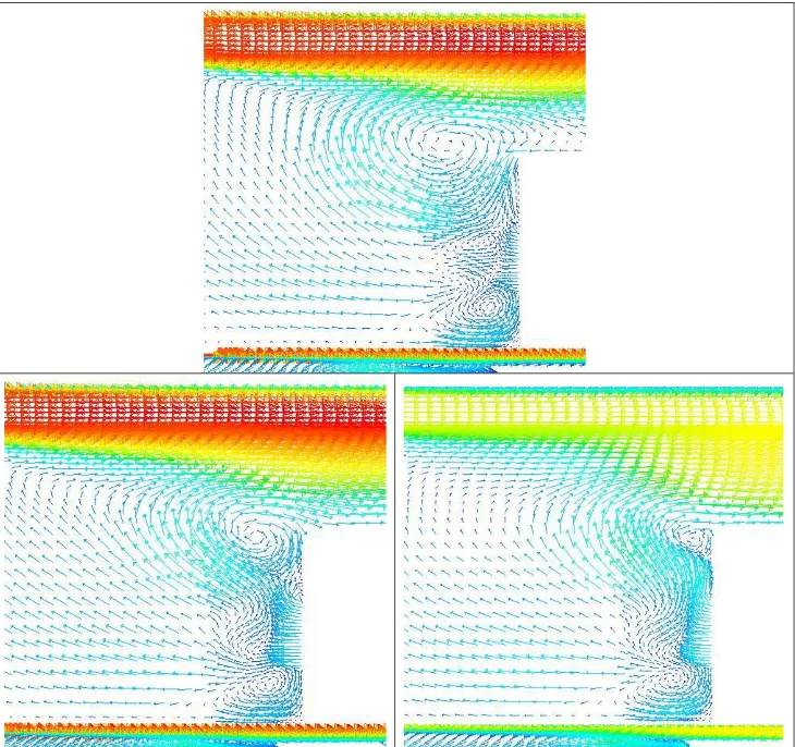
Flow field and flame ... 63
5.3
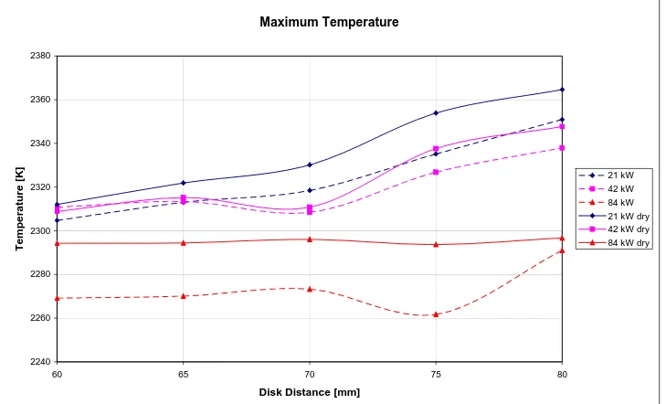
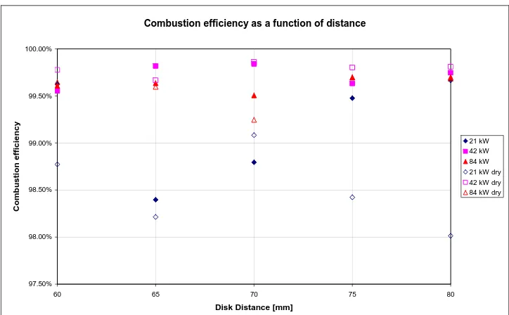
Effect of moisture... 72
5.5
Combustion instabilities ... 79
6
Conclusions and future perspectives ... 96
References... 98
Abstract
In the present study numerical simulations are performed to characterize the hydrogen combustion in a double cavity Trapped-Vortex Combustor (TVC). This combustor utilizes two trapped vortices in two cavities to improve flame stability and to provide low pressure drop. Good performances characteristics are obtained injecting a sufficient amount of fuel and air directly into the first cavity. The two cavities are obtained mounting three axisymmetric disks on a tube passing through their centrelines. The geometry and the configuration of this TVC are very similar to that studied by Hsu et al. 1995 and refer to a facility in the Casaccia (Rome) research center of the Italian National Agency for New Technologies, Energy and the Environment (ENEA).
The numerical studies were made using a commercial 3-D CFD code. A turbulent steady-state model with finite rate chemistry and second-order accuracy is used to simulate the TVC flowfields. The turbulence-chemistry interaction is provided by the Eddy Dissipation Concept (EDC). This model allows the inclusion of detailed chemical mechanisms in turbulent flows. In the present analysis of reacting flow the chemical kinetic model needed to simulate the hydrogen combustion consists of 37 reactions involving 14 species.
In order to evaluate the thermo fluid dynamics in the TVC a parametric study has been conducted. Variable parameters include the length of the first cavity, the power, the equivalence ratio, the humidity of the air and the inlet air composition and temperature.
Results from the analysis provide valuable information on the flow and flame structure and on the combustion process demonstrating the versatility and efficiency of burning hydrogen in a double cavity TVC.
List of symbols
Upper Case:Symbol Description Units
A Area [m2];
C Molar concentration [mol/m3];
Cp Constant-pressure specific heat [J/(kg K)];
Cv Constant-volume specific heat [J/(kg K)];
D Diffusivity [m2/s]; Da Damkoelhler Number [-]; Ea Activation Energy [kJ/kg]; F Force [N]; Fr Froude Number [-]; Gr Grashof Number [-];
H Enthalpy or disk distance [J] or [m];
HHV Higher Heating Value [J/kg];
Ka Karlovitz Number [-];
J Diffusive heat flux [kg/(s m2)];
L-J Lennard-Jones coefficient [-];
LHV Lower Heating Value [J/kg];
Le Lewis Number [-];
M Number of chemical reactions [-];
MW Molecular Weight [g/mol];
Ma Mach Number [-];
N Number of chemical species [-];
Pr Prandtl Number [-];
Ru Universal Gas Constant [kJ/(kg K)];
Re Reynolds Number [-]; Ri Richardson Number [-]; S Burning velocity [m/s]; Sc Schmidt Number [-]; T Temperature [K]; V Volume [m3]; X Mole Fraction [-]; Y Mass fraction [-]; Lower Case:
Symbol Description Units
d Diameter [m];
e energy per unit mass [kJ/kg];
f Frequency or mixture fraction [Hz] or [-];
g Gravitational acceleration [m/s2];
k Rate coefficient of reaction [-];
l length [m];
t Time [s];
p Pressure [Pa];
q Heat Flux [W/m2],
r,θ,z Cylindrical coordinate system [m,° or rad,m];
u velocity component in x- or axial direction [m/s]; v velocity component y- or radial direction [m/s];
w velocity component z-direction [m/s];
x,y,z Cartesian coordinate system [m];
Greek symbols:
Symbol Description Units
α Thermal diffusivity [m2/s];
δ Thickness [m];
ε Dissipation rate of turbulent kinetic energy [m/s3];
Φ Equivalence ratio [-];
κ Turbulent kinetic energy [m2/s2];
λ Thermal conductivity [J/(s m K)]; μ Dynamic viscosity [N s/m2]; ν Kinematic viscosity [m2/s]; ρ Density [kg/m3]; σ Normal stress [N/m2]; τ Shear stress [N/m2];
ω Mass rate of production of species [kg/(s m3)];
Ω Vorticity [rad/s];
Acronyms:
Symbol Description _____
AFRL Air Force Research Laboratory; APU Auxiliary Power Unit;
ATS Advanced Turbine System; AVC Advanced Vortex Combustion; CEC California Energy Commission; DLN Dry Lean NOx;
DOE Department Of Energy; EDC Eddy Dissipation Concept;
GE General Electric;
ICAO International Civil Aviation Organization; IGCC Integrated Gasification Combined Cycle; LES Large Eddy Simulation;
LBO Lean Blow Out;
LECTR Low Emission Combustion Test and Research; NETL National Energy Technology Laboratory; PSR Perfect stirred Reactor;
RQL Rich-burn, Quick-mix/quench, Lean burn;
SERDP Strategic Environmental Research and Development Program; TVC Trapped Vortex Combustor;
1 Introduction
1.1 Background and motivations
Combustion is a subject of great relevance from the scientific and technological point of view. The scientific interest is associated with the variety of physical processes which are encountered and with the inherent multi-disciplinary character of the subject, which involves Fluid Mechanics, Chemistry, Thermodynamics and the environmental science. The technological relevance is instead associated with the vast spectrum of industrial and engineering applications in which combustion is used. In almost all cases, chemical reactions, i.e. the combustion process, through which heat is produced, develop within a turbulent flow field. The characteristics and the evolution of the combustion process is strictly dependent on the property of the turbulent field and on the way fuel and oxidizer are mixed. The state of the mixedness of the reactants divides the combustion, and the flames, in two classes: premixed and non-premixed (or diffusive). In a premixed combustion fuel and oxidizer are mixed at the molecular level prior to the occurrence of any significant chemical reaction. Contrarily, in a diffusion combustion, the reactants are initially separated, and reaction occurs only at the interface between the fuel and the oxidizer, where mixing and reaction both take place.
In both classes of flames, depending on the combustion device’s operating range, important design criteria are the avoidance of flashback and liftoff, two conditions of instability. Flashback occurs when the flame enters and propagates through the burner tube or port without quenching; while liftoff is the condition where the flame is not attached to the burner tube or port hub, rather, is stabilized at some distance from the port. A poor stability of the flame can be obtained attempting to burn fuel in lean mixture combustion regimes to reduce the consumption or the pollutant emissions (furnaces, aircraft engines, turbo-reactors, etc.).
Combustion stability is often achieved through the use of recirculation zones to provide a continuous ignition source which facilitates the mixing of hot combustion products with the incoming fuel and air mixture. Swirl vanes, bluff bodies and rearward facing steps are commonly employed to establish recirculation zones for flame stability. Each method creates a low velocity zone of sufficient residence time and turbulence levels such that the combustion process becomes self-sustaining. The challenge, however, is the selection of a flame stabilizer which ensures both performance (emissions, combustor acoustic and pattern factor) and cost goals are met.
As opposed to conventional combustion systems which rely on swirl stabilization, the TVC employs cavities to stabilize the flame and grows from the wealth of literature on cavity flows [Hsu et al., 1995, Sturgess and Hsu, 1997, Straub et al., 2000, Roquemore et al., 2001]. Much of this effort examines the flow field dynamics established by the cavities, as demonstrated in aircraft wheel wells, bomb bay doors and other external cavity structures. Cavities have also been studied as a means of cooling and reducing drag on projectiles and for scramjets and waste incineration [Gharib and Roshko, 1987]. Very little work, however, exists on studying cavity flameholders for subsonic flow [Roquemore et al., 2001]. and none at all for lean premixed operation for potential use in a land based gas turbine engine
The actual stabilization mechanism facilitated by the TVC is relatively simple. A conventional bluff or fore body is located upstream of a smaller bluff body - commonly referred to as an aft body - at a prescribed distance commensurate with cold flow stabilization studies [Hsu et al., 1995, Sturgess and Hsu, 1997, Roquemore et al., 2001]. The flow issuing from around the first bluff body separates as normal, but instead of developing shear layer instabilities which in most circumstances is the prime mechanism for initiating blowout, the alternating array of vortices are conveniently trapped
or locked between the two bodies. The very stable yet more energetic primary/core flame zone is now very resistant to external flow field perturbations, yielding extended lean and rich blowout limits relative to its simple bluff body counterpart.
Due to its configuration, the system has greater flame holding surface area and hence will facilitate a more compact primary/core flame zone; which is essential in promoting high combustion efficiency and reduced emissions. Incorporation of transverse struts (Roquemore et al., 2001), which enhance the mixing/interaction of hot combustion products with the cooler premixed fuel and air, further reinforces the merits of the TVC as an excellent candidate for a lean-premixed combustion system. Furthermore, since part of combustion occurs within the recirculation zone, a typically flameless (Mild or Flox) regime can be achieved.
The objectives of this thesis are the evaluation of the performances and the stability regimes of a double cavity TVC by means of numerical simulations. The simulations are performed with a commercial code since this combustor is used in the industrial field.
Another aim of this research is to contribute to improve the knowledge and understanding of the physics involved in the TVC combustion and cover the lack of results regarding the use of hydrogen as fuel with this kind of combustor.
1.2 Structure of the thesis
The approach taken writing the thesis is to present and discuss some of the theoretical and practical elements needed to understand the model used and to relate the results obtained to practical applications.
The section 2 is structured to give all the fluid mechanics and thermochemistry fundamentals useful to a better comprehension of the arguments treated in the following sections.
The section 3 contains a brief review of the TVC state of the art and development, followed by a description of the TVC geometry taken into consideration. Furthermore an outline of the TVC behaviour under certain working conditions is given.
The numerical combustion modelization is described in section 4. It deals with a description of the approach used to solve the physical model needed to analyze the TVC performances. The computational domain and the mesh properties are first shown and then the main characteristic of the model with some reminds to the original articles/books to gather further information are given. Finally, in section 5 and 6 the results of the simulations and discussion are presented. The results are ordered following the phenomenological consequences due to the variation of the variables reported in the test matrix.
2 Theoretical Background
In this chapter, some important concepts related to combustion processes are examined. A review of some essential topics such as the basic properties of the ideal-gas mixtures, the stoichiometry and the thermo physical properties of the fuel (hydrogen) is briefly given. Successive paragraphs deal with the conservation equations for multicomponent reacting mixtures and relatives dimensionless governing parameters, the study of premixed and non-premixed flames and some basic chemical kinetics concepts. Then an outline of the elementary steps involved in the H2-O2 chemical
mechanism and in the oxides of nitrogen formation is given.
Details can be found in reference books [e.g. Kuo 1986, Williams 1985 …] so only the main concepts are summarized in the following.
2.1 Review of some property relations
2.1.1 Ideal-Gas Mixtures
Two important and useful concepts used to characterize the composition of a mixture are the constituent mole fractions and mass fractions. Considering a multicomponent mixture of gases composed of N1 moles of species 1, N2 moles of species 2, etc.. the mole fraction of species i, Xi is
defined as the fraction of the total number of moles in the system that are species:
tot i i i i N N N N N N X = + + + + = ... ... 2 1 2-1
Similarly, the mass fraction of species i, Yi, is the amount of mass of species i compared with the
total mixture mass:
tot i i i i m m m m m m Y = + + + + = ... ... 2 1 2-2
Mole fractions and mass fractions are readily converted from one to another using the molecular weights of the species of interest and of the mixture:
mix i i i MW MW X Y = , i mix i i MW MW Y X = 2-3
The partial pressure can be related to the mixture composition and total pressure as:
P X
Pi = i 2-4
For ideal gas mixtures, many mass- (or molar-) specific mixture properties are calculated simply as mass (or mole) fraction weighted sums of the individual species-specific properties. For example, mixture enthalpies are calculated as.
∑
= i i i mix Yh h , =∑
i i i mix X h h 2-52.1.2 Stoichiometry
The stoichiometric quantity of oxidizer is just that amount needed to completely burn a quantity of fuel. If more than a stoichiometric quantity of oxidizer is supplied, the mixture is said to be fuel lean, or just lean; while supplying less than the stoichiometric oxidizer results in a fuel-rich, or rich mixture. The stoichiometric oxidizer- (or air-) fuel ratio (mass) is determined by writing simple atom balances, assuming that the fuel reacts to form an ideal set of products. For a hydrocarbon fuel given by CxHy, the stoichiometric relation can be expressed by the a global reaction mechanism (see
2.3) as
(
2 2)
2 2 3.76 2 2 76 . 3 N xCO yH O aN O a H Cx y + + → + + 2-6 Where 4 y x a= +It is assumed, in the following that the simplified composition for air is 21% O2 and 79% N2 (by
volume) i.e. that for each mole of O2 in air, there are 3.76 moles of N2.
The stoichiometric air-fuel ratio can be found as
fuel air stoic fuel air stoic MW MW a m m F A 1 76 . 4 = ⎟ ⎟ ⎠ ⎞ ⎜ ⎜ ⎝ ⎛ = ⎟ ⎠ ⎞ ⎜ ⎝ ⎛ 2-7
Where MWair and MWfuel are the molecular weights of the air and the fuel, respectively.
The equivalence ratio, Φ, is commonly used to indicate quantitatively whether a fuel-oxidizer mixture is rich, lean, or stoichiometric. The equivalence ratio is defined as
( )
( )
stoic( )
( )
stoic A F A F F A F A = = Φ 2-8From the definition:
For fuel-lean conditions, we have 0<Φ<1, For stoichiometric conditions, we have Φ=1, And for fuel-rich conditions, we have 1<Φ<∞.
2.1.3 Hydrogen properties
Hydrogen is the fuel used in the simulations. In this section its main thermo physical properties are reported.
At standard temperature and pressure, hydrogen is a colourless, odourless, non-metallic, tasteless, highly flammable diatomic gas.
Dihydrogen (hydrogen gas) is highly flammable and will burn at concentrations of 4% or more H2
in air. The enthalpy of combustion for hydrogen is -286 kJ/mol; it burns according to the following global reaction:
(
kJ mol)
kJ O H O H 2 572 286 / 2 2+ 2 → 2 + 2-9When mixed with oxygen across a wide range of proportions, hydrogen explodes upon ignition. Hydrogen burns violently in air. It ignites automatically at a temperature of 560°C. Pure hydrogen-oxygen flames burn in the ultraviolet colour range and are nearly invisible to the naked eye, as illustrated by the faintness of flame from the main Space Shuttle engines. Another characteristic of hydrogen fires is that the flames tend to ascend rapidly with the gas in air causing less damage than hydrocarbon fires.
In the following tables the hydrogen main properties and a comparison with other fuels of the ignition and flammability properties are reported.
H2
Phase Gas
Melting point [K] 14.01
Boiling point [K] 20.28
Heat of fusion [kJ/mol] 0.117
Heat of vaporization [kJ/mol] 0.904
Gas Constat R [kJ/kg K] 4.124
Density ρ (300 K) [kg/m3] 0.0819
Specific heat cp (300 K) [kJ/kg K] 14.307
Thermal conductivity k (300 K) [W/m °C] 0.182
Thermal diffusivity α [m2/s] 1.55E-04
Dynamic Viscosity μ [kg/m s] 8.90E-06
Higher Heating Value HHV [kJ/kg] 141850
Lower Heating value LHV [kJ/kg] 120010
Tab. 2-1: Hydrogen Thermo Physical properties.
H2 CH4 C3H8
Minimum ignition energy [mJ] 0.02 0.28 0.25
Ignition temperature [K] 858 810 783
Adiabatic flame temperature [K] 2384 2227 2268
Limits of flammability (% by volume in Air) 4.1-75 4.3-15 2.2-9.5
Maximum laminar flame velocity [cm/s] 270 38 40
Diffusivity [cm2/s] 0.63 0.2
Minimum quenching distance at 1 atm [cm] 0.06 0.25 0.19
Normalized flame emissivity (200 K and 1 atm) 1 1.7 1.7
Fig. 2-1 shows the explosion limits of a H2-O2 mixture. It can be noticed that there are distinct regions in temperature-pressure coordinates where a stoichiometric mixture will and will not explode. The temperatures and pressures correspond to the initial charging conditions of a spherical vessel containing the reactants.
1 10 100 1000 10000 390 400 410 420 430 440 450 460 470 480 490 500 510 520 530 540 550 560 570 580 Temperature [°] Pre ssu re [mm H g ] No Explosion Explosion
Fig. 2-1: Explosion limits for a stoichiometric hydrogen-oxygen mixture in a spherical vessel.
2.2 Principles of combustion
2.2.1 Conservation equations for multicomponent reacting systems
Turbulent combustion is a multi-scale problem where complexity lies in the interaction between fluid dynamics and chemistry.
The main aim of this chapter is to provide a theoretical background of the main conservation equations used to study turbulent reacting flows.
0 = ⋅ ∇ + ∂ ∂ v t r ρ ρ 2-10
Which is the equation of continuity for the mixture.
For a multicomponent system the equation of continuity for a component i is:
i i i i i v Y YV t Y ρ ρ ω ρ + ⋅∇ +∇⋅ = ∂ ∂ r r 2-11
In a general multicomponent system there are N equations of this kind (or N-1 if the equation for the mixture is used). The addition of these equations gives the equation of continuity for the mixture.
The ωi in each species continuity equation is determined by the phenomenological chemical kinetic
expression (see sec. 2.3.1 for details):
(
)
∏
∑
= = ⎟⎟⎠ ⎞ ⎜⎜ ⎝ ⎛ − − = N j u j u k a k M k k i k i i i k j k T R p X T R E T B W 1 ' 1 , , , exp ' '' ν α ν ν ω 2-12Where M is the total number of chemical reactions occurring and N is the total number of chemical species present.
For what concerns the partial differential momentum equation, the basic assumption is that we are dealing with continuous, isotropic, and homogeneous media. We shall consider the special case of a Newtonian fluid, that is, a fluid exhibiting a linear relationship between shear stress and rate of deformation, resulting in the Navier-Stokes equation.
The momentum equation in indicial notation is:
(
)
∑
= + ∂ ∂ = ⎥ ⎥ ⎦ ⎤ ⎢ ⎢ ⎣ ⎡ ∂ ∂ + ∂ ∂ N k i k k j ji j i j i Y f x x u u t u 1 ρ σ ρ 2-13σji is the stress tensor, fk is the force per unit mass on the k-th species.
Substituting the constitutive equation:
⎟ ⎟ ⎠ ⎞ ⎜ ⎜ ⎝ ⎛ ∂ ∂ + ∂ ∂ + ∂ ∂ ⎟ ⎠ ⎞ ⎜ ⎝ ⎛ − + − = i j j i ij k k ij ij x u x u x u pδ μ μ δ μ σ 3 2 ' 2-14
in the momentum equation, we obtain the Navier-Stokes equation:
(
)
∑
= + ⎥ ⎥ ⎦ ⎤ ⎢ ⎢ ⎣ ⎡ ⎟ ⎟ ⎠ ⎞ ⎜ ⎜ ⎝ ⎛ ∂ ∂ + ∂ ∂ + ∂ ∂ ⎟ ⎠ ⎞ ⎜ ⎝ ⎛ − + − ∂ ∂ = ⎥ ⎥ ⎦ ⎤ ⎢ ⎢ ⎣ ⎡ ∂ ∂ + ∂ ∂ N k i k k i j j i ij k k ij j j i j i f Y x u x u x u p x x u u t u 1 3 2 ' μ δ μ ρ μ δ ρ 2-15Where μ’ is the bulk viscosity, μ is the dynamic viscosity. The difference
μ μ λ 3 2 '− =
is the second viscosity. The usual practice is to employ the hypothesis made by Stokes in 1845: 0
'=
μ
in combustion processes also.
The law of conservation of energy for a fluid contained within a volume element is:
(
)
k ki N k i k i j i ji i i i t i t u V Y f x u Q x q x e u t e , 1 ,∑
= + + ∂ ∂ + + ∂ ∂ − = ⎥ ⎦ ⎤ ⎢ ⎣ ⎡ ∂ ∂ + ∂ ∂ σ ρ ρ & 2-16 Where:The first term on the left side is the rate of accumulation of internal and kinetic energy; The second is the net rate of influx of internal and kinetic energy by convection;
The third is the net rate of heat addition due to the heat flux q; which contains the conduction heat, the energy flux caused by interdiffusion processes and the Dufour effect (heat flux produced by concentration gradients);
The fourth is the rate of heat added by heat source;
The last two terms are the net rate of work done on system by surroundings.
et is the energy stored per unit mass defined as:
2 i i t u u e e = + 2-17
Summation of the internal and kinetic/mechanical energy.
Vk is the mass diffusion velocity of the k-th velocity.
The mechanical-energy equation, obtained from the momentum equation multiplying it by ui, is:
∑
= + ∂ ∂ = ⎥ ⎥ ⎥ ⎦ ⎤ ⎢ ⎢ ⎢ ⎣ ⎡ ∂ ∂ + ∂ ∂ N k i i k k j ji i j i i j i i u f Y x u x u u u t u u 1 , 2 1 2 1 ρ σ ρ 2-18The internal energy equation, obtained subtracting (2-16) from (2-18), is:
∑
= + ∂ ∂ + + ∂ ∂ − = ⎥ ⎦ ⎤ ⎢ ⎣ ⎡ ∂ ∂ + ∂ ∂ N k i k i k k j i ji i i i i Y f V x u Q x q x e u t e 1 , , ρ σ ρ & 2-19The Fick’s first law for a binary system is:
(
A)
A A AB AA
A v v V D Y
J =ρ − =ρ =−ρ ∇ 2-20
Where D is the mass diffusivity, vA is the velocity of the species A with respect to the stationary
coordinate axes, v is the mass-average velocity of the system and V the mass diffusion velocity. The Fick’s second law of diffusion states:
A AB A C D t C = ∇2 ∂ ∂ 2-21
This equation is generally used for diffusion in solids or stationary liquids and for equimolar counterdiffusion in gases.
Other necessary equations in multicomponent systems are listed below. The ideal-gas equation, stating that
∑
= = N i i i u W Y T R p 1 ρ 2-22The relationship between Xi and Yi :
(
)
∑
= = N j i i i i i W Y W Y X 1 / / 2-23The multicomponent diffusion equation obtained through rigorous derivation from the kinetic theory for i=1, 2, … , N species is:
(
)
(
)
∑
(
)
∑
∑
= = = ∇ ⎟ ⎟ ⎠ ⎞ ⎜ ⎜ ⎝ ⎛ − + − + ∇ − + − = ∇ N j N j i i j j ij j i j i j i i i N j i j ij j i i T T Y Y D X X f f Y Y p p p X Y V V D X X X 1 1 1 α α ρ ρ r r r r 2-24Where αj is the thermal diffusion coefficient of species j.
Physically this equation states that concentration gradients may be supported by diffusion velocities, pressure gradients, the differences in the body force per unit mass on molecules of different species, and thermal-diffusion effects.
For what concerns the solution of a multicomponent-species system, if the diffusion velocities can be substituted by Fick’s Law in the species and energy equations, then in a system with N species there are N+6 unknowns.
The N+6 equations to be solved are: 1 overall mass continuity
3 momentum equations 1 energy equation
N – 1 species equations
1 equation of state 1 equation relating all Yi
If the diffusion velocities must be solved from the diffusion equation for a multicomponent system, there will be 5N+6 unknowns. Further there are 4N equations:
3N diffusion equations
N equations relating Xi to Yi
In the preceding paragraphs, we have discussed some important equations for laminar reacting flows. For laminar flows, the adjacent layers of fluid slide past one another in a smooth, orderly manner. The only mixing possible is due to molecular diffusion. The velocity, temperature, and
concentration profiles measured in laminar flow with a high-sensitivity instrument will be quite smooth.
At very high Reynolds or Grashof numbers the flow becomes turbulent. In turbulent flow, eddies move randomly back and forth and across the adjacent fluid layers. The flow no longer remains smooth and orderly.
It is very difficult to give a precise definition of turbulence. In the following some of the characteristics of turbulent flows are listed:
• Irregularity: all turbulent flows are irregular, or random. This makes a deterministic approach to turbulence problems impossible; one relies on statistical methods.
• Diffusivity: the diffusivity of turbulence, which causes rapid mixing and increased rates of momentum, heat and mass transfer, is another important feature of all turbulent flows.
• Large Reynolds number: turbulent flows always occur at high Reynolds numbers. Turbulence often originates as an instability of laminar flows if the Reynolds number becomes too large. The instability is related to the interaction of viscous terms and non linear inertia terms in the equation of motion.
• Three-Dimensional Vorticity Fluctuations: turbulence is rotational and three dimensional. It is characterized by high levels of fluctuating vorticity. For this reason, vorticity dynamics plays an essential role in the description of turbulent flows.
• Dissipation: turbulent flows are always dissipative. Viscous shear stresses perform deformation work which increases the internal energy of the fluid at the expense of the kinetic energy of the turbulence. Turbulence needs a continuous supply of energy to make up for these viscous losses.
• Continuum: turbulence is a continuum phenomenon, governed by the equations of fluid mechanics. Even the smallest scales occurring in a turbulent flow are ordinarily far larger than any molecular length scale.
• Turbulent Flows Are Flows: turbulence is not a feature of fluids but of fluid flows. Most of the dynamics of turbulence is the same in all fluids, whether like they are liquids or gases, if the Reynolds number of the turbulence is large enough; the major characteristics of turbulent flows are not controlled by the molecular properties of the fluid in which turbulence occur.
Even chemically non-reacting turbulent flows are highly challenging due to the above characteristics. When chemical reactions occur, the problems become even more complex, since the turbulent fluid flow is further coupled with chemical kinetics and quit often with phase changes. This is why the study of turbulent reacting flows is one of the most challenging fields of engineering science.
The turbulent flame is often accompanied by noise and rapid fluctuations of the flame envelope. In addition to the characteristics of non-reacting turbulent flows mentioned earlier, some of the flames are described briefly in the following:
• The flame surface is very complex, and it is difficult ot locate the various surfaces that are used to characterize laminar flames.
• Also due to the enhanced transport properties the turbulent flame speed is much greater than the laminar flame speed.
• The height of a turbulent flame is smaller than that of a laminar flame at the sme flow rate, fuel-air ratio, and burner size. This is shown by comparison of direct photographs. At a given velocity, the flame height decreases as the intensity of the turbulence increases.
As the turbulent motion is random and irregular, it has a broad range of length scales and can be treated statistically taking into consideration some type of averaged quantities. There are two different averaging procedures commonly used: conventional time averaging (also called Reynolds averaging) and mass-weighted averaging (also called Favre averaging).
The time-averaged conservation equations can be obtained by applying the Reynolds averaging procedure. But Reynolds averaging for variable density flow introduces many other unclosed correlations between any quantity and density fluctuations then to avoid this difficulty, mass-weighted averages (called Favre averages) are usually preferred. We can define a mass-mass-weighted generic quantity as:
ρ ρf
f =
~
2-25
Any quantity f may be split into mean and fluctuating components as: ''
~
f f
f = + 2-26
Using this formalism, the averaged balance equations become: Continuity
( )
~ =0 ∂ ∂ + ∂ ∂ j j u x t ρ ρ 2-27Momentum (assuming that the body force is negligible)
( )
~(
~~)
(
ij i '' j '')
j i j i j i u u x x p u u x u t ρ ρ ∂ τ −ρ ∂ + ∂ ∂ − = ∂ ∂ + ∂ ∂ 2-28Where the last term on the right-hand side represents the turbulent stresses due to turbulent diffusion of momentum. Chemical species
( )
(
)
i k k i k i i k i k i i k u Y x Y D x x Y D x Y u x Y t ρ ρ ρ ρ ρ ⎟⎟⎠+ϖ& ⎞ ⎜⎜ ⎝ ⎛ − ∂ ∂ ∂ ∂ + ∂ ∂ ∂ ∂ = ∂ ∂ + ∂ ∂ '' '' ~ '' ~ ~ ~ 2-29Energy (total enthalpy)
( )
( )
(
)
j i ij j i ij j j j j j j j i j j x u x u u h q x x p u x p u x p u h x h t ∂ ∂ + ∂ ∂ + − − ∂ ∂ + ∂ ∂ + ∂ ∂ + ∂ ∂ = ∂ ∂ + ∂ ∂ ~ ~ '' '' '' '' ~ ~ ~ ~ ρ ρ τ τ ρ 2-30 Where: ⎟ ⎟ ⎠ ⎞ ⎜ ⎜ ⎝ ⎛ ∂ ∂ + ∂ ∂ + ∂ ∂ ⎟ ⎠ ⎞ ⎜ ⎝ ⎛ − = i j j i ij k k ij u u x u x u δ μ μ μ τ 3 2 'j j x T q ∂ ∂ − = λ
The left-hand side represents the average rate of change of ρh per unit volume per unit time;
The first two terms on the right-hand side represent the pressure work due to macroscopic motion; The third term is the work due to turbulence;
The forth term is the transport heat due to conduction; The fifth term is the turbulent diffusion of ρh;
The last two terms represent the dissipation due to molecular friction.
2.2.2 Dimensionless governing parameters
In flow problems, the conservation equations can often be written in forms involving dimensionless ratios of various quantities and coefficients. The mean dimensionless ratios involved in the combustion and invoked in the following sections are reported here. These parameters characterizes the fresh mixture, the reacting flow from a global point of view and the turbulence-combustion interactions for premixed and non-premixed flames.
The Reynolds number is defined as:
forces Viscous forces Inertial ul ul = = = ν μ ρ Re 2-31
The turbulence Reynolds number based on integral length (lt) scale is defined as:
ν t
T
l u ''
Re = 2-32
The Lewis number (or Lewis-Semenov number) is defined as:
transport mass of Rate transport energy of Rate D D C Le p = = = α ρ λ 2-33
The Prandtl number is defined as:
transport energy of Rate transport momentum of Rate Cp = = = α ν λ μ Pr 2-34
The Schmidt number is defined as:
transport mass of Rate transport momentum of Rate D Sc=ν = 2-35
Le and Sc may be defined for each pair of species in multicomponent mixtures. From the above we
Pr
Sc
Le= 2-36
In the following the Le number is approximately assumed 1(where not differently specified).
An important parameter in combustion is the Damköhler number. This parameter appears in the description of many combustion problems and is quite important in understanding turbulent premixed flames (see following section). It is defined by:
( )
( )
L L t t c t m c t S l u l l Da / '' / δ τ τ τ τ = = = 2-37It is defined for the largest eddies and corresponds to the ratio of the integral time scale (τt
turbulence time, characteristic flow time) to the chemical timescale (τc flame time). The subscript m
stands for mechanical. δL is the laminar flame thickness, SL the laminar flame velocity and u’ the
velocity fluctuations. From the definition, the Da can also represent the product of the length scale ratio and the reciprocal of a relative turbulence intensity. Thus, once fixed the length-scale ratio, the Da falls as turbulence intensity increases.
The Karlovitz number is defined as:
( )
( )
2 2 3 2 1 '' 1 ⎟⎟ ⎠ ⎞ ⎜⎜ ⎝ ⎛ = ⎟⎟ ⎠ ⎞ ⎜⎜ ⎝ ⎛ ⎟⎟ ⎠ ⎞ ⎜⎜ ⎝ ⎛ = = = − K L L L t K m c K a l S u l l l Da K δ δ τ τ 2-38It corresponds to the smallest eddies (Kolmogorov) and is the ratio of the chemical time scale to the Kolmogorov time.
2.2.3 Basic flame types
In combustion processes, fuel and oxidizer are mixed and burned. There are several combustion categories based upon whether the fuel and oxidizer is mixed first and burned later (premixed) or whether combustion and mixing occur simultaneously (non premixed). Each of this categories can be further subdivided based on whether the fluid flow is laminar or turbulent. Next figure shows examples of combustion systems that belong to each of these categories, which will be discussed in the following sections.
Fig. 2-2: Example of combustion systems ordered with respect to premixedness and flow types (Warnatz 1996).
2.2.3.1 Premixed Flames
The coupling of heat and mass transport and chemical reaction leads to a spatial structure, the flame, which determines the path from reactants to products.
The flame is caused by a self-propagating exothermic reaction which is accompanied by a reaction zone. The structure of a laminar-premixed flame is schematically shown in Fig. 2-3:
Fig. 2-3: Schematic representation of premixed flames structure.
Premixed flame structure can be divided into four zones: unburned zone (cold reactants zone), preheat zone, reaction zone and burned gas zone (products zone). The unburned mixture of fuel and oxidizer is delivered to the preheat zone at prefixed conditions, where the mixture is warmed by upstream heat transfer from the reaction zone. In the reaction zone, the fuel is rapidly consumed and the bulk of chemical energy is released. The thickness of the flame front depends on pressure and on initial temperature and equivalence ratio. This thin flame front implies steep species and temperature gradients, which provide the driving forces for the flame to be self-sustaining. In the reaction zone, temperature is high enough for creating a large radical pool. Finally, in the burned zone, radicals recombine, and both temperature and major species concentrations approach their equilibrium values. However, the concentrations of minor species in this region can deviate substantially from their equilibrium values.
The velocity with which a flame front propagates with respect to the unburned fuel-oxidizer mixture is called the laminar burning velocity, SL, and is strongly dependent upon fuel and oxidizer type,
equivalence ratio and temperature of unburned fuel-oxidizer mixture.
Considering a premixed flammable mixture in a long tube, open at both ends, ignited from one end. A combustion wave will travel down the tube starting from the ignition point. The characteristic burning velocity depends upon the fuel. For most hydrocarbon-air stoichiometric mixtures this velocity is about 0.4 to 0.6 m/s, for hydrogen-air mixures this velocity is several meters per second. The velocity of this wave is controlled by the diffusion of heat and active radicals. Indicating the unburned fuel-oxidizer mixture velocity with v, the speed of the flame front vfr is v-SL. From the last
relation three possible idealized situations may occur, depending on the relation between v and SL.
First, if v>SL the flame will move away from the burner, i.e., the flame will blow off. If v=SL, the
flame will keep its position relative to the burner surface, and be “aerodynamically stabilized”. In this case, neglecting possible radiative losses from the flame to the surroundings, the enthalpy in the fuel is solely manifest in the temperature of the burned gases, and the flame is referred to as an “adiabatic” or “free” flame. The temperature corresponding to an adiabatic flame is the maximum flame temperature that can be achieved for a given fuel-oxidizer composition. If v<SL, the flame
will move towards the burner and will attempt to enter the burner (flash back). Since the pores of the idealized burner are assumed to prevent the flame from entering the burner, the flame will
transfer heat to the burner to lower the actual burning velocity to the flow velocity; in this condition the flame is referred to be as being ‘stabilized’ by the burner surface.
Turbulent premixed flames are of practical importance, being encountered in many useful devices (Spark-Ignition Engines, Gas-turbine Engines, Gas Burners…), while, paradoxically, their description is still a matter of uncertainty, or at least controversy.
Unlike a laminar flame, which has a propagation velocity that depends uniquely on the thermal and chemical properties of the mixture, a turbulent flame has a propagation velocity that depends on the character of the flow, as well as on the mixture properties. The turbulent flame speed, ST, is defined
as the velocity at which unburned mixture enters the flame zone in a direction normal to the flame.
Fig. 2-4: A superposition of instantaneous reaction fronts obtained at different times (left) and a turbulent flame “brush” associated with a time averaged view of the same flame.
From this figure can be noticed the effect of the turbulence. The effect is to wrinkle and distort an essentially laminar flame front.
Remembering that in a turbulent flow various length scales exist simultaneously and that the smallest scale, the Kolmogorov micro scale, lK, represents the smallest eddies in the flow. These
eddies rotate rapidly and have high vorticity, resulting in the dissipation of the fluid kinetic energy into internal energy, i.e., fluid friction results in a temperature rise of the fluid. At the other extreme of the length-scale spectrum is the integral scale, lt, which characterizes the largest eddy sizes. The
basic structure of a turbulent flame is governed by the relationships of lK and lt to the laminar flame
thickness, δL. The laminar flame thickness characterizes the thickness of a reaction zone controlled
by molecular, not turbulent, transport of heat and mass. More explicitly, three turbulent combustion regimes are defined using the Damköhler and the Karlovitz numbers defined before, three turbulent premixed combustion regimes may be identified in terms of length (lt/δL) and velocity (u’/SL) ratios
(Tab. 2-3).
Ka<1 (Da>1) Ka>1 and Da>1 Da<<1
Wrinkled laminar flames Flamelets in eddies Distributed reactions Flame is thinner than all
turbulent scales
Small turbulent scales may enter the flame front
All turbulent time scales are smaller than the chemical time
scale
When Ka<1, the chemical time scale is shorter than any turbulent time scales and the flame
thickness is smaller than the smallest turbulent scale. In this regime the flame front is thin, has an inner structure close to a laminar flame and is wrinkled by turbulence motions.
For τk<τc<τt (Ka>1 and Da>1) the turbulent integral time scale is still larger than the chemical time
scale but the Kolmogorov scales are smaller than the flame thickness and are able to modify the inner flame structure. The flame can no longer be identified as a laminar flame front but is still a wrinkled flame.
For Da<1 turbulent motions have shorter characteristics times than the chemical reaction time τc:
mixing is fast and the overall reaction rate is limited by chemistry.
1.00E-04 1.00E-02 1.00E+00 1.00E+02 1.00E+04 1.00E+06 1.00E+08
1.00E+00 1.00E+01 1.00E+02 1.00E+03 1.00E+04 1.00E+05 1.00E+06 1.00E+07 1.00E+08
ReT Da 102 Weak Turbulence 10-2 104 Reaction Sheets lK/δL=1 u’/SL=1 Flamelets in eddies 10-2 l0/δL=1 102 104 Distributed Reactions
Fig. 2-5: Important parameters characterizing turbulent premixed combustion. Conditions satisfying the Williams-Klimov criterion for the existence of wrinkled flames lie above the dash line lK=δL, and conditions satisfying the
Damkohler criterion for distributed reactions fall below the dash dot line l0=δL.
The flame regime that might occur in practical combustion can be estimated from Fig. 2-5 [Turns 2000] once provided sufficient information characterizing the turbulent flowfield, in particular once
identified five dimensionless parameters interrelated in the figure. The parameters are: lK/δL, l0/δL,
ReT, Da and u’/SL. There are three separated regions on the graph of Da versus ReT corresponding to
the three regimes defined before. The three regions are separated by the dash dot line l0/δL=1 and
the dash line lK/δL=1. Above the dash line reactions take place in thin sheets, the wrinkled
laminar-flame regime; below the dash dot line reactions will take place over a distributed region in space. The region between the lines is the flamelets in eddies regime.
2.2.3.2 Non-premixed flames
In a non-premixed flame, combustion occurs at the interface between the fuel gas and the oxidant gas, and the burning process depends more on the rate of diffusion of reactants than on the rates of chemical processes involved. It is more difficult to give a general treatment of diffusion flames because no simple measurable parameter analogous to the burning velocity can be defined.
Non-premixed flames include more complex chemistry than those of premixed flames, because the equivalence ratio covers the whole range from zero (air) to infinity (pure fuel). Rich combustion occurs on the fuel side, lean combustion on the air side. The flame front, which is usually characterized by intense luminescence, is fixed to regions near the location of the stoichiometric composition, since this is where the temperature is highest. Thus, unlike premixed flames, non-premixed flames do no propagate and , therefore, cannot be characterized by a laminar flame speed. The flame cannot propagate into the fuel without oxidizer or into the oxidizer without fuel and, thus, is fixed to the interface.
The flame of a match, of a candle, and of the familiar gas-jet burner are all of this type.
To achieve an idea of the nature of the non-premixed combustion the most used example is the jet flame. The jet flame is relatively uncomplicated, and, because of this, it has been the subject of many theoretical and experimental investigations [Chigier 1972].
A typical flame of this type can be produced readily using coaxial cylindrical tubes (circular nozzles). As the fuel flows along the flame axis, it diffuses radially outward, while the oxidizer diffuses radially inward. The flame surface is nominally defined to exist where the fuel and oxidizer meet in stoichiometric proportions. We have to note that, although the fuel and oxidizer are consumed at the flame, the equivalence ratio still has meaning since the products composition relates to a unique value of Φ. The products formed at the flame surface diffuse radially both inward and outward.
The region where chemical reactions occur is generally quite narrow. As seen in Fig. 2-6, where a typical composition profile of a hydrogen-air diffusion flame is shown, the reaction zone occurs in an annular region. This is true until the flame tip is reached.
The observed shapes of non-premixed flames may be divided into two classes. If the ratio of the duct radii is such that more air is available than what is required for completer combustion, then an overventilated flame is formed and the flame boundary converges to the cylinder axis. On the other hand, if the air supply is insufficient for complete burning, then underventilated flame is reduced in which the flame surface expands to the outer tube wall.
For simple laminar diffusion flames on circular nozzles flame height is mostly used to characterize the flame. For an overventilated flame the flame length, Lf is simply determined by the axial
location where
(
=0, =)
=1Fig. 2-6: Diffusion flame structure: species variations through a diffusion flame at a fixed height above the fuel jet tube [Gaydon 1960].
As reported in Kuo 1986, it can be demonstrated that the laminar flame height is proportional to the volumetric flow rate and inversely proportional to the mass diffusivity. The variation of the premixed flame height as a function of jet velocity is shown in Fig. 2-7 while for a turbulent non-premixed flame the flame height is proportional to the port size.
Fig. 2-7: The variation of flame height and character as a function of jet velocity [Gaydon 1960].
Non-premixed turbulent flames burn in a turbulent flow field, and for low turbulence intensities the flamelet concept can be used again.
Examples of turbulent non-premixed flames are: • Conventional gas turbines;
• Bi-propellant rocket engines; • Diesel engines;
• Cement kilns, glass furnaces, boiler furnaces; • Turbojet afterburners;
• Most fires (like forest fires), pool flames; • Coal/wood combustion;
For any particular application, some of the issues the designer is faced with are as follows (importance of each may change depending on the nature of the application): combustion intensity and efficiency, flame stability shape and size, heat transport and pollutant emissions.
Because of the safety considerations mentioned above and the ease with which such flames can be controlled, non-premixed flames are mostly used in industrial furnaces and burners, the majority of practical combustion systems. With current concern for pollutant emissions, however, this advantage becomes something of a liability in that there is also less ability to control, or tailor, the combustion process for low emissions.
Unless very sophisticated mixing are used, non premixed flames show a yellow luminescence (Fig. 2-8), caused by glowing soot particles, which are formed by fuel rich chemical reactions in the rich domain of the non-premixed flames; the non-premixed turbulent jet flames have brushy or fuzzy edges similar to premixed flames.
Fig. 2-8:Turbulent non-premixed flames.
As mentioned before, the height of the laminar flame depends on the flow rate. As the flow rate increases, turbulence begins to influence the flame height and a transitional regime can be seen. Over this transitional, the increasing turbulence levels with flowrate result in the fully turbulent flames being shorter than their laminar counterparts.
Concerning flame stability, at sufficiently low flowrates, the base of a jet flame lies quite close to the burner tube outlet and is said to be attached. As the fuel flowrate is increased, holes begin to form in the flame sheet at the base of the flame, and with further increase in the flowrate, more and more holes form until there is no continuous flame close to the burner port (Liftoff). At sufficiently large flow rate, the flame blows out.
2.3 Chemical kinetics and reaction mechanisms
Chemical kinetics is the part of chemical science dealing with the quantitative study of the rates of chemical reactions and of the factors upon which they depend. It also deals with the interpretation of the empirical kinetic laws in terms of reaction mechanisms. A reaction mechanism is a collection of elementary reactions necessary to describe an overall reaction. We remind to e.g. Kuo 1986, Glassman 1996, Peters 1993, Smoke 1991, Turns 2000 for more details.
Some of the essential features of chemical kinetics which occur frequently in this work will be reviewed in the following sections.
2.3.1 Rates of reactions
All chemical reactions, whether hydrolysis or combustion, take place at a definite rate, depending on the conditions of the system. Some important conditions are concentrations of the chemical compounds, temperature, pressure, presence of a catalyst or inhibitor, and radiative effects.
The rate of reaction may be expressed in terms of the concentration of any reactant as the rate of decrease of the concentration of that reactant (the rate of consumption of the reactant). It may also be expressed in terms of product concentration as the rate of increase of the product concentration. A conventional unit for reaction rate is moles/m3 sec.
The rate law for an elementary reaction can be described by the equation: ...
... D E F
C B
A+ + + ⎯⎯→k + + 2-39
Where A,B,C… denote the different species involved in the reaction.
A rate law describes an empirical formulation of the reaction rate, i.e. the rate of formation or consumption of a species in a chemical reaction.
The law of mass action, which is confirmed by numerous experimental observations, states that the rate of disappearance of a chemical species is proportional to the products of the concentrations of the reacting chemical species, each concentration being raised to a power equal to the corresponding stoichiometric coefficient.
Looking at the consumption of species A, the reaction rate can be expressed according to
[ ]
[ ] [ ] [ ]
.... c b a C B A k dt A d =− ⋅ 2-40Where a,b,c.. are reaction orders with respects to the species A,B,C… and k is the rate coefficient of the reaction (or specific reaction rate constant). The sum of all exponents is the overall reaction order.
For the reverse reaction (characterized here by the subscript r) one obtains the rate law for the production of A:
[ ]
[ ] [ ] [ ]
.... f e d r D E F k dt A d = ⋅ 2-41Since mechanisms may involve many elementary steps and many species, the compact notation can be used to represent both the mechanism and the individual species production rates.
For the mechanism, one can write:
∑
∑
= = ⇔ N j j ji N j j ji A A 1 1 '' ' ν ν for i=1,2,…,L. 2-42Where ν’ji and ν’’ji are the stoichiometric coefficients on the reactants and products side of the
equation, respectively, for the jth species and ith reaction. Aj is the arbitrary specification of all
The following three relations compactly express the net production rate of each species in a multistep mechanism:
[ ]
∑
= = = L i i ji j j q dt A d 1 ν ω& for j=1,2,…,N. 2-43 Where(
ji ji)
ji ν '' ν' ν = − 2-44 And[ ]
∏
[ ]
∏
= = − = N j j ri N j j fi i ji ji A k A k q 1 '' 1 ' ν ν 2-45The last equation defines the rate of progress variable, qi, for the ith elementary reaction.
The specific reaction-rate constant, for a given reaction, is independent of the concentrations [Aj]
and depends only on the temperature. In general, k is expressed as:
⎟⎟ ⎠ ⎞ ⎜⎜ ⎝ ⎛ − = T R E AT k u a n exp 2-46
Where ATn represents the collision frequency and the exponential term is the Boltzmann factor, specifying the fraction of collisions that have an energy greater than the activation energy Ea. The
values of B, n and Ea are based on the nature of the elementary reaction. For given chemical
changes, these parameters are neither functions of the concentrations nor of temperature.
2.3.2 Hydrogen Chemical Mechanism
The H2-O2 reaction mechanism has been extensively studied over the years and has already got
widespread application such as in high energy rocket engines. More recently it has become extremely evident that combustion of hydrogen with air will continue to receive increasing application primarily because of the non-polluting characteristics of this combustion process.
In this contest it is essential to discuss the hydrogen oxygen combustion reactive mechanism.
It has been observed that under ambient conditions of temperature, hydrogen and oxygen do not enter into any direct reaction between them in absence of a catalyst. It is further seen if a mixture of hydrogen and oxygen gets exposed to light oxygen gets activated usually by way of dissociation. In the presence of the sensitizers of Cl, N2O and NH3, a set of secondary reactions take place and form
H atoms. These H atoms enter into a reaction with the activated oxygen thus forming H2O.
Relying heavily on Glassman 1996, the oxidation of hydrogen is as follows. The initiation reactions are
M H H M
H2 + ⇒ + + (very high temperature)
H HO O
Chain-reaction steps involving O, H and OH radicals are OH O O H + 2 ⇒ + OH H H O+ 2 ⇒ + H O H OH H2 + ⇒ 2 + OH OH O H O+ 2 ⇒ + .
Chain-terminating steps involving O, H and OH radicals are the three-body recombination reactions: M H M H H + + ⇒ 2 + M O M O O+ + ⇒ 2 + M OH M O H + + ⇒ + M O H M OH H + + ⇒ 2 + .
To complete the mechanism, the reactions involving HO2, the hydroperoxy radical, and H2O2,
hydrogen peroxide need to be included. When
M HO M
O
H + 2 + ⇒ 2 +
Becomes active, then the following reactions come into play:
OH OH H HO2+ ⇒ + O O H H HO2+ ⇒ 2 + OH O O HO2+ ⇒ 2+ And 2 2 2 2 2 HO H O O HO + ⇒ + H O H H HO2+ 2 ⇒ 2 2+ With 2 2 2 2O OH H O HO H + ⇒ + OH O H H O H2 2+ ⇒ 2 + 2 2 2 2O H HO H H + ⇒ + M OH OH M O H2 2+ ⇒ + +
Depending upon the temperature, pressure and extent of reaction, the reverse reactions of all of above can be important; therefore in modelling H2-O2 system as many as 40 reactions can be taken
into account involving eight species: H2, O2, H2O, OH, O, H, HO2 and H2O2.
No. Reaction
A
n
Ea
Rh.1 H+O2=OH+O 2.00E+14 0 70.3
Rh.2 H2+O=OH+H 1.80E+10 1 36.93
Rh.3 H2O+O=OH+OH 5.90E+09 1.3 71.25
Rh.4 H2+OH=H2O+H 1.17E+09 1.3 15.17
Rh.5 H+O2+Ma=HO2+Ma 2.30E+18 -0.8 0
Rh.6 H+HO2=OH+OH 1.50E+14 0 4.2
Rh.7 H+HO2=H2+O2 2.50E+13 0 2.93
Rh.8 OH+HO2=H2O+O2 2.00E+13 0 4.18
Rh.9 H+H+Ma=H2+Ma 1.80E+18 -1 0
Rh.10 H+OH+Ma=H2O+Ma 2.20E+22 -2 0
Rh.11 HO2+HO2=H2O2+O2 2.00E+12 0 0
Rh.12 H2O2+M=OH+OH+M 1.30E+17 0 190.38
Rh.13 H2O2+OH=H2O+HO2 1.00E+13 0 7.53
Rh.14 O+HO2=OH+O2 2.00E+13 0 0
Rh.15 H+HO2=O+H2O 5.00E+12 0 5.9
Rh.16 H+O+M=OH+M 6.20E+16 -0.6 0 Rh.17 O+O+M=O2+M 6.17E+15 -0.5 0 Rh.18 H2O2+H=H2O+OH 1.00E+13 0 15.02 Rh.19 H2O2+H=HO2+H2 4.79E+13 0 33.26 Rh.20 O+OH+M=HO2+M 1.00E+16 0 0 Rh.21 H2+O2=OH+OH 1.70E+13 0 200
Rh.22 O+N2=N+NO 1.82E+14 0 319.02
Rh.23 O+NO=N+O2 3.80E+09 1 173.11 Rh.24 H+NO=N+OH 2.63E+14 0 210.94 Rh.25 NO+M=N+O+M 3.98E+20 -1.5 627.65 Rh.26 N2+M=N+N+M 3.72E+21 -1.6 941.19 Rh.27 N2O+O=NO+NO 6.92E+13 0 111.41 Rh.28 N2O+O=N2+O2 1.00E+14 0 117.23
Rh.29 N2O+N=N2+NO 1.00E+13 0 83.14
Rh.30 N+HO2=NO+OH 1.00E+13 0 8.31
Rh.31 N2O+H=N2+OH 7.60E+13 0 63.19
Rh.32 HNO+O=NO+OH 5.01E+11 0.5 8.31
Rh.33 HNO+OH=NO+H2O 1.26E+12 0.5 8.31
Rh.34 NO+HO2=HNO+O2 2.00E+11 0 8.31
Rh.35 HNO+HO2=NO+H2O2 3.16E+11 0.5 8.31
Rh.36 HNO+H=NO+H2 1.26E+13 0 16.63
Rh.37 HNO+M=H+NO+M 1.78E+16 0 203.7
a
H2=1.0 H2O=6.5 O2=0.4 N2=0.4.
Units are cm3, mol, s, kJ and K
2.3.3 Oxides of nitrogen formation
Nitric oxide is an important minor species in combustion because of its contribution to air pollution. The detailed nitrogen chemistry involved in the combustion of methane is reported in the GRIMECH mechanism [GRI-Mech 3.0]. In the combustion of fuels that contain no nitrogen, nitric oxide is formed by three chemical mechanisms or routes that involve nitrogen from the air: the thermal or Zeldovich mechanism, the Fenimore or prompt mechanism and the N2O intermediate
mechanism. There is growing evidence for the possibility of a fourth route involving NNH. The thermal mechanism dominates in high-temperature combustion over a fairly wide range of equivalence ratios, while the Fenimore mechanism is particularly important in rich combustion. It appears that the N2O-intermediate mechanism plays an important role in the production of NO in
very lean, low-temperature combustion processes. Recent studies show the relative contributions of the three mechanisms in premixed and diffusion flames.
The thermal or Zeldovich mechanism consists of two chain reactions:
N NO N O+ 2 ⇔ + O NO O N+ 2 ⇔ +
Which can be extended by adding the reaction
H NO OH
N+ ⇔ +
This three-reaction set is referred as the extended Zeldovich mechanism. In general, this mechanism is coupled to the fuel combustion chemistry through the O2, O, and OH species; however, in process
where the fuel combustion is complete before NO formation becomes significant, the two processes can be uncoupled. In this case, if the relevant time scales are sufficiently long, one can assume that the N2, O2, O, and OH concentrations are at their equilibrium values and N atoms are in steady
state. These assumptions greatly simplify the problem of calculating the NO formation. If we make the additional assumption that the NO concentrations are much less than their equilibrium values, the reverse reactions can be neglected. This yields the following rather simple rate expression:
[ ]
[ ] [ ]
eq eq f N O N k dt NO d 2 1 . 2 = 2-47Within flame zones proper and in short-time-scale, postflame processes, the equilibrium assumption is not valid. Superequilibrium concentrations of O atoms, up to several orders of magnitude greater than equilibrium, greatly increase NO formation rates. This superequilibrium O (and OH) atom contribution to NO production rates is sometimes classified as part of the so-called prompt-NO mechanism.
The activation energy for the first NO reaction is relatively large; thus, this reaction has a very strong temperature dependence. As a rule-of-thumb, the thermal mechanism is usually unimportant at temperatures below 1800 K. Compared with the time scales of fuel oxidation processes, NO is formed rather slowly by the thermal mechanism; thus, thermal NO is generally considered to be formed in the postflame gases.
The N2O-intermediate mechanism is important in fuel-lean (F<0.8), low temperature conditions.
M O N M N O+ 2+ ⇔ 2 + NH NO O N H + 2 ⇔ + NO NO O N O+ 2 ⇔ +
This Mechanism becomes important in NO control strategies that involve lean premixed combustion, which are currently being explored by gas-turbine manufacturers.
The Fenimore mechanism is intimately linked to the combustion chemistry of hydrocarbons [Lefebvre 1983]. Fenimore discovered that some NO was rapidly produced in the flame zone of laminar premixed flames long before there would be time to form NO by the thermal mechanism, and he gave this rapidly formed NO the appellation prompt NO. The general scheme of the Fenimore mechanism is that hydrocarbon radicals react with molecular nitrogen to form amines or cyano compounds. The amines and cyano compounds are then converted to intermediate compounds that ultimately form NO.
In the atmosphere, nitric oxide ultimately oxidizes to form nitrogen dioxide, which is important to the production of acid rain and photochemical smog. Many combustion processes, however, emit significant fractions of their total oxides of nitrogen as NO2. the elementary reactions responsible
for forming NO2 prior to exhausting of the combustion products into the atmosphere are the
following: OH NO HO NO+ 2 ⇔ 2 + (formation) OH NO H NO2 + ⇔ + (destruction) 2 2 O NO O NO + ⇔ + (destruction)
Where the HO2 radical is formed by the three-body reaction:
M HO M
O
H + 2 + ⇔ 2 +
The HO2 radicals are formed in relatively low-temperature regions; hence, NO2 formation occurs
when NO molecules from high temperature regions diffuse or are transported by fluid mixing into HO2 rich regions. The NO2 destruction reactions are active at high temperatures, thus preventing the
formation of NO2 in high-temperature zones.
2.4 Mild Combustion
One of the major advantages into the application of the TVC combustors is the possibility to achieve mild combustion that is one of the promising techniques proposed to control pollutant emissions from combustion plants. It is characterized by high pre-heating of combustion air and massive recycle of burned gas before reaction.
Real-size burners achieve flameless conditions by feeding the combustion air and the fuel through separated or coflowing high velocity jets into the combustion chamber. The air jets entrain a large amount of burned gases from the combustion chamber before reacting with the fuel. Consequently oxygen concentration in combustion air is lower than in traditional flames, while turbulence is higher. Chemical reactions occur at lower rates (compared with mixing ones) and are less limited by mass diffusion. Consequently, the combustion region is no longer concentrated close to the flame front but is extended over the whole combustion chamber, resulting in a volumetric rather than superficial combustion and in the complete disappearance of the flame, hence the name flameless. As a result, mild oxidation can easily control thermal gradients by avoiding the formation of hot
spots in the furnace and by enabling reduction of thermal NOx production without compromising combustion efficiency. Another peculiar characteristic is the reduction of combustion noise, which is set to values similar to those generated by a non-reacting jet [Wünning 1997].

![Fig. 2-7: The variation of flame height and character as a function of jet velocity [Gaydon 1960]](https://thumb-eu.123doks.com/thumbv2/123dokorg/2846208.5632/27.892.230.661.594.902/fig-variation-flame-height-character-function-velocity-gaydon.webp)