Experimenting a distributed passive MPPT based on mini-battery-packs to cope with short-term critical
partial shadings on PV-generators
Rosario Carbone*, Giuseppe A. Maiolo
“Mediterranea” University of Reggio Calabria, Department D.I.I.E.S., Via Graziella, Reggio Calabria 89123, Italy Corresponding Author Email: [email protected]
https://doi.org/10.18280/mmc_b.870301
Received: 12 February 2018 Accepted: 16 April 2018
ABSTRACT
The common use of by-pass diodes, to contain power generation losses and to avoid “hot-spot” phenomena in presence of short-term, repetitive and critical partial shadings on a PV-field, is experimentally investigated, for demonstrating that bypass diodes are not the optimum choice. Active distributed maximum power point trackers (DMPPTs) can offer a better solution; nevertheless, they are based on complex circuitries and control algorithms, with a reduced reliability and additional power losses. In this contest, the aim of the paper is to present and discuss experimental results obtained by testing a homemade PV-generator prototype in which only a wisely designed and distributed mini-storage based on commercial rechargeable batteries is introduced, to be employed as a “passive” DMPPT, without any active DC/DC converter. The prototype is also experimented to make a comparative performance analysis (i) without bypass diodes, (ii) with bypass diodes and (iii) by introducing our mini-battery-pack, under identical partial shadings, artificially caused and characterized by different degrees of criticality. Experiments demonstrate that wisely designed distributed mini-battery-packs, based on commercial rechargeable batteries, can effectively operate as a passive DMPPT able to cope with short-term critical partial shadings for avoiding “hot-spot” issues and for guaranteeing a significant improvement of the net generated power together with the conventional storage task. Keywords:
PV-generators, short-term partial shadings, hot-spot on PV-cells, distributed battery storage, bypass diodes, distributed MPPTS
1. INTRODUCTION
On a photovoltaic (PV) field, partial shadings cause relevant losses of power generation together with some other important issues as the well-known and damaging “hot-spot” and/or breakdown phenomena on shaded PV-cells [1-5]. This is because, above of all possible configurations, PV-strings are typically connected in series and if only few PV-cells of the same module are shaded they force its weak current value to all the remaining series-connected PV-cells and modules; therefore, the whole power generated by the PV-string could be very reduced despite the modules which are well irradiated. In case of a critical partial shading (i.e. only a single PV-cell is shaded in an entire PV-module), the voltage at the terminals of the shaded PV-cell can significantly reverse and it becomes a dissipative load. In this situation, the temperature of the shaded PV-cell increases and the hot-spot can arise; furthermore, if the reversed voltage increases very much, the shaded PV-cell can also arrive in its breakdown region.
To attempt to avoid this phenomena, one or more antiparallel diodes (bypass diodes) are conventionally mounted on board of commercial PV-modules [1, 5]; usually, three bypass diodes are installed within the junction box of each commercial PV-module, that is to say one for each group (or sub-module) of 20 (or 24) series-connected PV-cells.
Nevertheless, it has been already demonstrated that standard bypass diodes do not completely eliminate hot-spotting [1, 5]. In fact, when a bypass diode is forward biased because of a partial shading, a low reverse voltage it is imposed across the relative sub-module. If the partial shading
is “critical”, that is to say only one (or a very low number) of the PV-cells of the same sub-module is shaded, non-shaded PV-cells also contribute to increase the reverse voltage of the shaded PV-cell. Furthermore, the partially shaded sub-module can still generate a significant amount of current and, therefore, the shaded PV-cell can dissipate a large power; consequently, it can heat up and if the temperature rise becomes sufficiently large, accelerated ageing and/or permanent damage can affect the shaded PV-cell.
In this contest, active distributed maximum power point trackers (DMPPT) have been also widely introduced and studied [6-11]. These optimizers, usually, are DC/DC boost or buck/boost power electronic converters, which can be dedicated to a single PV-module to make it independent from other of the same PV-string; therefore, they are theoretically able to catch the maximum power point (MPP) of each PV-module and of the whole PV-string. Recently DMPPTs was proposed to be introduced also at the sub-PV-module level for further reducing both power generation losses and hot-spotting issues of shaded PV-cells also under critical partial shadings (i.e. shading of only a few number of PV-cells of the same module) [8-11]. In practice for each commercial PV-module it has been proposed to introduce, directly within the junction box of the PV-module, three independent small power DC/DC converters for reducing the number of the series connected PV-cells whose generated power can be independently optimized; the effectiveness of this proposal was demonstrated also by means of experiments. Nevertheless, active DMPPTs are based on complex and expensive circuitries and control logics; furthermore, in some critical partial shading conditions,
Modelling, Measurement and Control B
Vol. 87, No. 3, September, 2018, pp. 113-121 Journal homepage: http://iieta.org/Journals/MMC/MMC_Bconduction losses on their static switches can be relevant and significant over voltages can also appear at the terminals of their sensible components [12-14]. Also, the DC voltage at the terminals of the central inverter is not constant and, therefore, its control could result very complex and its conversion efficiency cannot be always maximized [15].
In [12] it has been also demonstrated, through both Spice simulations and laboratory tests, that low power active MPPTs distributed at the sub-module level could be improved in their efficiency (and also in the stability of their output voltage) by introducing within its circuitry a battery-based mini-storage. In particular, by replacing the conventional output capacitor with a properly designed mini-battery-pack, it has been shown that the net power (which is the output power of the DC/DC converter net of power losses on its active and passive components) can be further maximized, thanks to the reduction of the conduction losses on the static switches of the converter. With these improvements, the entire PV-module can cope with the partial shading phenomena in a better way; in fact, battery-based mini-storage can make independent the small part of the PV-generator which is shaded, by integrating (or substituting) the generation of the shaded PV-cells with the energy accumulated inside the battery-pack. Furthermore, until batteries are not deeply discharged and depending on its capacity value, they can avoid high variations of the output voltage (together with its sign reversing), also in presence of critical partial shadings. Consequently, they can guarantee the generation of the maximum available power together with the optimal operation of the central inverter, also avoiding any voltage reversing and hot-spotting phenomena on the shaded PV-cells.
That said, the aim of this paper is to present and discuss experimental results obtained by testing a homemade PV-generator prototype in which only a properly designed battery based mini-storage is introduced, to be employed as a distributed and “passive” MPPT, without using any additional DC/DC converter.
With the aim of maximizing the net generated power also in presence of critical partial shadings (only on a very few number of PV-cells) and for avoiding, at the same time, any hot-spotting issue, the mini-storage battery-pack is designed for being connected in parallel to a group of a very small number (only 4) of series-connected PV-cells.
An identical homemade and conventional prototype of PV-generator with no batteries will be also tested to compare the different prototypes and to give evidence that conventional bypass diodes are not the best solution for coping with partial shading issues.
2. SOME INSIGHTS ABOUT PARTIAL SHADING ISSUES AND LIMITS OF BYPASS-DIODES
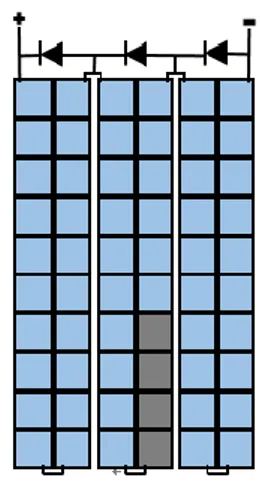
Partial shading effects on a PV-generator are analyzed with specific reference to a conventional and commercial PV-module, usually based on 60 or 72 series-connected (6x6)" mono or poly crystalline PV-cells. In practice, the PV-module is utilized as a case-study for analyzing effects of critical partial shadings that can affect only a few number of its PV-cells (as evidenced in the Figure 1) or, as a very critical situation, even a single PV-cell.
A conventional PV-module is usually built with 60 (or 72) PV-cells in the form of 3 sub-modules of 20 (or 24) series-connected PV-cells, each endowed with an anti-parallel diode
(bypass diode) across its +/- terminals; the 3 sub-modules are then connected in series one to each other. This widely used situation can be graphically represented as in the Figure 1.
Figure 1. Schematic of a commercial PV-module based on
60 PV-cells endowed with 3 bypass diodes
In case of uniform solar irradiation of the PV-module, each PV-cell generates approximately 0.6V, then each sub-module voltage will be of about +12V; as a consequence, each bypass diode will be reverse biased and it does not conduct any current; in this situation, all the 60 PV-cells of the module are fully connected in series and they generate the same current value to an external load or to the next PV-module of the same string.
If the solar irradiation is reduced but only on a few number of PV-cells of the same sub-module (i.e. because of a partial shading), the current value generated by the shaded PV-cells diminishes, causing an identical reduction on the current generated by the remaining well irradiated and series-connected PV-cells of the module. The reduction of the current value generated by the well-irradiated PV-cells causes an increasing of their positive voltage, Vnon-sh; the more the
reduction of its generated current the more Vnon-sh tends to its
open circuit maximum value [4].
At this stage, it is relevant to underline that the voltage at the terminals of the shaded PV-cells, Vsh, depends not only
from the criticality of the partial shading phenomenon but also from the load condition.
With reference to a single PV-module, first of all, the Kirchhoff law simply reveals that the aforesaid voltage Vsh is
equal to the difference between the voltage at the terminal of the whole PV-module (which is also the load voltage), Vload,
and the sum of the voltages of all the remaining non-shaded PV-cells of the module, ∑Vnon-sh:
Vsh = Vload - ∑Vnon-sh (1) For a fixed load condition and in case of a low intensity of the partial shading, Vload is again higher than ∑Vnon-sh and Vsh
is positive. Nevertheless, the more the intensity of the partial shading increases the more the module (and load) current decreases; the more Vload decreases the more ∑Vnon-sh increases
and, finally, the more Vsh tends to reverse.
From equation (1), for a fixed intensity of the partial shading, the reversing process of Vsh obviously depends also from the
load condition; as an example, in case of the zero resistance load condition (short circuit) Vsh rapidly tends to the value
Also, in the worst case of a full shaded PV-cell, independently from the load condition, the current circulating on the PV-module is null and each voltages of the remaining non-shaded PV-cells, Vnon-sh, reaches its open circuit
maximum value, so maximizing the term ∑Vnon-sh; also, Vload
is null (for any load) and, as a consequence, Vsh assumes the
highest and most dangerous reversed value -∑Vnon-sh which can
reach the value of about -35V.
It is clear that a shaded PV-cell can be irreversibly damaged if the voltage reverses beyond its own breakdown value (i.e., for a conventional (6x6)” PV-cell, about -12÷-20 V). Also, shaded PV-cells operate as a dissipative load and, if the dissipated power is high enough, they can be irreversibly damaged because of an over-temperature (hot-spot). It is estimated that a single PV-cell can be seriously damaged if it dissipates for a long time a power that is more than two time its own maximum power (i.e., for a conventional (6x6)” PV-cell, about 2x4Wp = 8W) [4].
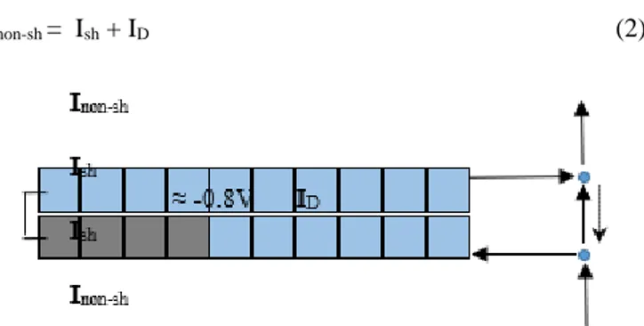
Of course, if a PV-module is endowed with its three conventional bypass diodes (as in Figure 1), when the voltage at the terminal of the sub-module containing the shaded PV-cells reverse below the value of about -0.7÷-0.8V, the bypass diode is forward biased and it switches on, avoiding much more reversing of the voltage of the shaded sub-module. Once the bypass diode of the shaded sub-module is conducting because of a partial shading, the electrical situation within the shaded sub-module can be schematically represented as in Figure 2.
Now, non shaded sub-modules can generate their maximum power because of its maximum current, Inon-sh, can freely
circulating through the forward biased bypass diode of the shaded sub-module. Furthermore, this situation could seem positive also because the reverse voltage of the bypassed diode, having a very small value (about -0.8V), induces the idea that it is not at all dangerous for any PV-cell of the shaded sub-module. Nevertheless, if the sub-module is partially shaded only on a few number of its PV-cells, it is still able to generate an internal own current, Inon-sh, that can also physically
circulating through the forward biased bypass diode. As evidenced in Figure 2, now the current in the partially shaded sub-module, Ish, the current in the forward biased bypass diode,
ID, and the current in the not shaded sub-modules, , Inon-sh, are
simply subjected to the Kirchhoff law:
Inon-sh = Ish + ID (2)
Figure 2. Schematic of the shaded sub-module whose bypass
diode is conducting the current ID at the voltage ≈ -0.8V
Obviously, equation (1) can be now applied also to the “bypassed” sub-module, simply revealing that:
Vsh ≈ - (0.8 + ∑Vnon-sh) , (3)
That is to say, the voltage at the terminals of the partially shaded PV-cells of the sub-module, Vsh, is negative and,
because of the voltage of each not shaded PV-cell, Vnon-sh, has
a positive value close to the open circuit value of about 0.6V, it can again assume a relevant reversed value. As an example, if only 4 PV-cells of the 20 series-connected PV-cells of the same sub-module are partially shaded (as it is represented in Figure 2), the voltage at the terminals of these shaded PV-cells tends to assume the value – (0.8 + 16x0.6) = -10.4 V. And, even if this reversed voltage is clearly not enough to directly induce the breakdown of the shaded PV-cells, it could induce the hot-spotting if its generated current, Ish, assumes a
significant value, depending on the intensity of the partial shading. In fact, if (as an example) Ish assumes a value of 3÷4
A the power dissipated on the 4 partially shaded PV-cells, PD4sh, can assume the value of about 31.2÷41.6 W. that is to
say each partially shaded PV-cell can dissipate a power, PD1sh,
of about 7.8÷10.4W, very close or even higher than its own hot-spot power value. Furthermore, because of possible fabrication defects and/or impurities, PV-cells could exhibit a large reverse current non-homogeneously distributed throughout the whole cell area; in fact, it could concentrate in small regions of slightly higher conductivity, where the silicon presents a higher concentration of defects/impurities. Such a localized power dissipation can produce a considerable increase of the temperature in that regions of the PV cell that are close to the impurity centers, thus giving rise to the hot-spot; if the heating of these regions exceeds the maximum value tolerated by the PV cell, this last can be permanently damaged [4].
The aforementioned theoretical analysis reveals that it would be of practical relevance to install more than three bypass diodes on board of a conventional PV-module based on 60 (or 72) series connected PV-cells; in fact, the more the number of the installed bypass diodes the more the partially shaded PV-cells will be protected against hot-spotting phenomena [1-2]. Theoretically, for avoiding hot-spotting for any criticality of partial shadings, it would be desirable to install one bypass diode for each couple of series connected PV-cells of the same module. However, this approach has not encountered the favor of PV-module producers since it requires significant technological cost and would cause also too much power dissipation when many bypass diodes are conducting. On the other hand, many studies have already demonstrated that critical partial shadings can be effectively mitigated by means of low-power DC/DC power converters distributed at the sub-module level [6], as briefly discussed in next section.
3. MAXIMUM POWER POINT TRACKERS (MPPT) DISTRIBUTED AT THE SUB-PV-MODULE LEVEL
One of the most effective way for coping with partial shading issues is that of introducing power optimizers (MPPTs) distributed at the sub-PV-module level [8-11]; they are theoretically able to catch the maximum available power of each sub-module. Furthermore, by replacing bypass diodes, they prevent the reversing of the sub-module voltage also in case of a critical partial shading, so avoiding hot-spotting on partially shaded PV-cells. In the following, a brief description of a MPPT architecture distributed at the sub-module level and based on low power DC-DC converters is firstly introduced
together with some considerations on their main advantages and also their practical limitations.
Then, a circuital modification based on the use of batteries, recently discussed and numerically tested in [12] is briefly recalled. A proposal of substituting low power active DC-DC converters with only wisely calibrated mini-battery-packs, distributed at a very deep sub-module level, is also introduced and described, before to be experimentally tested in next section 4.
3.1 Sub-module low power DC-DC converters
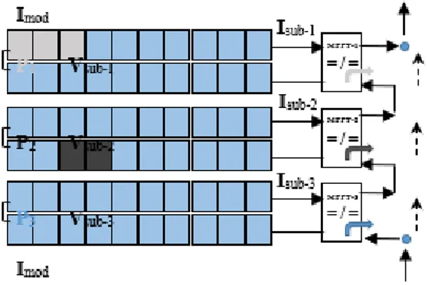
Figure 3 shows a schematic of a PV-module divided into three sub-modules each of one has in series a low power DC-DC converter operating as an MPPT in order to independently maximize the power that each sub-module can generate depending on its own solar irradiation conditions.
Figure 3. Schematic of a PV-module endowed with three
DC-DC low power converters, operating as active MPPTs distributed at the sub-module level
By this architecture, also in case of a critical partial shading, each sub-module can independently generate its own maximum available power (P1, P2 and P3) so guaranteeing the generation of the maximum available power of the whole PV-module (P1 + P2 + P3). Furthermore, distributed DC-DC converters do not make possible the reversing of voltages at the three sub-module terminals and any hot-spotting phenomena on PV-cells are strongly mitigated. The effectiveness of this kind of architecture was already fully studied and demonstrated in some previous papers [8-11].
Nevertheless, active DMPPTs are based on complex and expensive circuitries and control logics and these aspects can cause some issues related to costs and reduced reliability of the PV-generator; furthermore, because of DC-DC converter are in series with their own sub-modules, they have to operate at their respective full generated power and, as a consequence, conduction losses on their static switches can be relevant, especially when DC-DC converters have to operate with high values of their duty cycles [12]. Also, because of the three DC-DC converters are connected in series at their output terminals, each DC-DC converter has to generate its own maximum power, Pi, with the same value of the common output current,
Imod. This means that, under critical partial shadings, the output
voltage of the best-irradiated sub-module, Vsub-3, can become
a relevant over-voltage for some sensible components of its circuitry. In [13] it has been demonstrated that to avoid these kind of overvoltage’s it is necessary to add a complex central maximum power point tracking algorithm within the central inverter.
3.2 The proposed passive distributed MPPT based on mini-packs of commercial batteries
In [12] authors have already demonstrated that, in case of a boost type DC-DC converter utilized as low-power MPPT distributed at the sub-module level, the operating values of the duty cycles of the DC-DC converters can be reduced very much by simply substituting the conventional output capacitor of the converter with a wisely designed mini-battery-pack, and this immediately reduce their conduction losses. By this way, very low power DC-DC converter can be profitably distributed on board to a conventional PV-module at a major granularity. Nevertheless, by this way some problems related to major costs and complexity of the whole circuitry of low power DC-DC converter still remain; furthermore, in [12] it was also point out that if one would dedicate an optimizer to a very low number of series-connected PV-cells (lower than 10), wisely calibrated mini-battery-packs could be profitably used also without any active circuitry. In fact, as well known and already underlined in [16], for a fixed level of the solar irradiance and for a fixed temperature, the power delivered to a load by a PV-generator depends on the value of the load resistance; for this reason, active MPPTs are largely used, as recalled in section 3.1. On the other hand, it is also well known that, for varying solar irradiance (SI) levels, the variation of the MPPs directly involves the generated current values, while the voltage values remain almost constant. This means that a battery, in parallel with the PV-generator and the load (as shown in Figure 4), if wisely designed in its rated voltage value, Vn, can naturally
catch and maintain (within limits imposed by the capacity of the battery) a working point very close to the MPP, for any solar irradiance level and for any value of the load equivalent resistance (see Figure 4).
Figure 4. Working points and MPPs of a PV-generator under
SI variations, by using wisely calibrated batteries With some more detail, it is well known that, under standard conditions (i.e. 1000 W/m2 of solar irradiance, SI, and 25 °C
of PV-cells temperature, Tc) the voltage, Vmpp, to be put at the
terminals of a PV-generator for the generation of its maximum available power, has a value that is about the 80% of its open circuit voltage, Voc. Nevertheless, it is also well known that the
Vmpp value sensibly decreases if the working temperature, Tc,
of PV-cells increases (with respect to the standard value of 25 °C) and vice versa.
That said, once a sub-module has been fully planned an identified in terms of physical characteristics and number of its series-connected PV-cells, its theoretical maximum power voltage, Vmpp, under standard conditions can be easily
determined. Then, one can now attempt to design an effective passive MPPT based on a battery-pack to be put in parallel to such sub-module. Now, one of the most important problem to be solved is that of matching - as best as possible - the Vmpp
value with the rated voltage of the battery-pack, Vbatt, within
limits of commercial availability of batteries. Furthermore, variations of both the SI levels and mostly the Tc values have
to be also taken into account, as best as it is possible and, at such stage, a campaign of preventive and accurate experimental measurements under variable atmospheric conditions can give very important designing suggestions. Anyway, please consider that the main objective of this kind of design is that of identifying a passive and battery-based MPPT as good as possible, for guaranteeing to our sub-module: (i) a desired level of storage, (ii) the absence of any hot-spotting phenomenon and (iii) the generation of a net-power greater than that obtainable by using a simple bypass diode or a very low power DC-DC converter, for any solar irradiance condition and also in presence of partial expected on the sub-module installation site.
As a case-study and having in mind the possibility to cope with partial shading phenomena that can affect a very low number of PV-cells of the same PV-module, we have considered the possibility to profitably use very available, reliable, efficient and also cheap 1.2V AA NiMH rechargeable batteries, each of one having a capacity of 2100mAh. Concerning the choice of the batteries’ capacity, this last can be fixed and/or varied by simply fixing and/or varying the number of the batteries to be connected in parallel within the same pack, and this clearly depends from the criticality of the short term partial shading to be coped with.
About the design of the sub-module to whom dedicate the aforementioned kind of battery-pack, first of all, we have considered conventional and widely diffused (6x6)” poly-crystalline silicon PV-cells; then, for building the sub-module which guarantees the best matching with the 1.2V rated voltage of our batteries, we have dealt with the question of how choose the number of the PV-cells to be connected in series. From this point of view, theoretically, the best solution should be to put in series three PV-cells; in fact three series-connected PV-cells have an open circuit voltage, Voc, of about 1.8V that
is to say they also have a voltage value at the MPP, Vmpp, under
standard conditions, of about (0.8x1.8) = 1.44V which is a value very close to the operating voltage of the already chosen batteries. Nevertheless, once the sub-module with three series-connected PV-cells has been built, during some preventive experimental tests, the PV-cells revealed a reduced open circuit voltage value of about 1.6V and, consequently, also a reduced value for the Vmpp, under standard conditions, of about
1.28V. Furthermore, we have also considered that, having to accept an unavoidable error in centering the sub-module optimal voltage value under variable operating conditions, it is better to fix it at a lower value rather than at a higher value; this because, from the P-V curve of a PV-generator, it is very easy to note that, with respect to its maximum value, the generated power diminishes more quickly if the operating voltage is higher than Vmmp while it diminishes less quickly if
the operating voltage is lower than Vmmp. As a consequence,
we have decided to build our base sub-module for the 1.2V battery-pack by using 4 series-connected PV-cells; by this way,
our sub-modules experimentally revealed an open circuit voltage of about 2.1V also revealing a maximum power voltage, under standard conditions, of about 1.65V. Additionally, we have also considered the possibility to use a 2.4V battery-pack, by simply connecting in series 2 of our 1.2V batteries. In this case, the effectiveness of the 2.4V battery-pack was tested by connecting it in parallel to a mini-module based on both seven and eight series-connected PV-cells; some more details about these experiments are summarized in next section 4.
Anyway, even if the rated voltage of our battery-pack will result unavoidably “imperfect”, we expect to demonstrate with many experimental tests major effectiveness of our solution with respect to the conventional solution based on the use of a bypass diode, being already demonstrated the practical inefficacy of using a very low power DC-DC converter to be dedicated to a sub-module based on a number of series-connected PV-cells less than 10 [12].
4. EXPERIMENTAL TESTS
4.1 Description of the home-made prototype
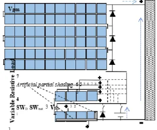
The electrical scheme of the homemade PV-generator used for experimental tests is shown in Figures 5 and 6.
The generator is built on the basis of a 60 (6x6)” PV-cells commercial module (with 250 Wp) which is series-connected to a homemade mini-module, built by using 8 series-connected commercial (6x6)” PV-cells.
Figure 5. Electrical scheme of the homemade PV-generator
used for experimental tests
As shown in Figure 5, we have built the mini-module with seven + different terminals: the first + terminal is relative to the PV-cell number 1, the second + terminal is relative to the PV-cell number 3 (being 3 the minimum number of series-connected PV-cells we would like to protect by means of a bypass diode or by a battery-pack), the third + terminal is relative to the PV-cell number 4 and so on until the + terminal of the last PV-cell number 8.
Finally, the whole PV-generator is loaded with a variable resistive load (we have used a rheostat with a range of 0÷10 , 300W of maximum power and 10 A of maximum current). By this way, by exposing our PV-generator prototype to the sun (as shown in the picture of Figure 6), it is possible to do a lot of different measurements for testing the effectiveness (and also the limits) of using bypass power diodes (we have used a widely diffused 10A “T10A60L” diode) for coping with partial shadings with different degree of criticality; as an alternative, it is possible to test also the idea of using wisely designed battery-packs based on commercial rechargeable batteries (for building our battery-packs we have used widely diffused “AA, 1.2V, NiMH, 2100 mAh” batteries).
In practice, by artificially producing a variable partial shading only on board of the mini-module (while the commercial PV-module remains well irradiated), it is possible to do three different kind of measurements, for monitoring the consequent “answer” of the whole PV-generator: (i) measurements without the bypass diode (in the Figure 5, switches SWD and SWbatt are OFF), (ii) measurements with the
bypass diode inserted at the terminals of the shaded mini-module (only the switch SWD is ON) and (iii) measurements
substituting the bypass diode with a battery-pack (the switch SWD is OFF while the switch SWbatt is ON).
Artificial partial shading on board of the mini-module characterized by different degrees of criticality can be simply obtained by artificially obscuring, in a variable percentage (from 0% to 100%) the PV-cell surfaces (see Figure 5). Furthermore, each level of the partial shading on the mini-module could interest both (uniformly) all the PV-cells or (not uniformly) only one PV-cell, as graphically evidenced also in the Figure 5.
Finally, by changing the number of the series-connected PV-cells of our mini-module, we can also test different effects of using a bypass diode or batteries in attempting to protect a group of a variable number of series-connected PV-cells, subject to critical partial shadings.
4.2 Measurements without and with bypass diodes
All Measurements summarized within this section are performed under the optimal load condition with no shadings. The first case-study is based on a mini-module constituted by 4 series-connected PV-cells, which are artificially exposed to a variable partial shading, Psh4, which uniformly interests all the four PV-cells of the mini-module. For each level of the partial shading, Psh4, two different solutions were tested: 1) without the bypass diode (SWD = OFF) and 2) with the bypass
diode (SWD = ON).
Table 1 summarizes the results obtained without inserting the bypass diode; the optimal resistance load with no shadings was 6.85.
Table 1. Results of measurements on a four PV-cells
mini-module, without inserting the bypass diode (SWD = OFF);
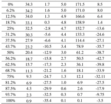
the mini-module is subject to a variable level partial shading, Psh4, uniformly distributed on all the four PV-cells Psh4 [%] Vgen [V] Vsh [V] Igen [A] Pgen [W] PDsh [W]
0% 34.3 1.7 5.0 171.5 8.5 6.2% 34.2 1.6 5.0 171.0 8.0 12.5% 34.0 1.3 4.9 166.6 6.4 18.7% 33.1 0.3 4.8 158.9 1.4 25% 32.5 -2.8 4.7 152.7 -13.6 31.2% 30.3 -5.6 4.4 133.3 -24.6 37.5% 27.9 -6.6 4.1 114.4 -27.1 43.7% 23.2 -10.5 3.4 78.9 -35.7 50% 20.4 -12.9 3.0 61.2 -38.7 56.2% 18.7 -15.8 2.7 50.5 -42.7 62.5% 15.7 -17,3 2.3 36.1 -39.8 68.7% 11.3 -21.2 1.6 18.1 -33.9 75% 9.3 -24.7 1.3 12.1 -32.11 81.2% 6.9 -27.5 1.0 6.9 -27.5 87.5% 4.3 -29.9 0.6 2.6 -17.9 93.7% 2.3 -32.5 0.3 0.7 -9.75 100% 0.9 -35.4 0.1 0.1 -3.5
From Table 1, we can underline that, when the 4 PV-cells of the mini-module are fully shaded (Psh4 = 100%), not only the power generated by the whole PV-generator, Pgen, is practically null but also the voltage at the terminal of the shaded mini-module, Vsh, is highly reversed, reaching a high
value of more than -35V; this means that each shaded PV-cell is subject to a significant reversed voltage of about -9V. Furthermore, once Vsh reversed, also the power of the shaded
mini-module, PDsh-m, is negative (dissipated) assuming a
dangerous value of about -43W in correspondence to a partial shading of about 56%; this means that each shaded PV-cell dissipates a relevant power of about -11W. In this situation, the temperature of the shaded PV-cells has reached the value of 50 °C (while the temperature of the non-shaded PV-cells of the main PV-module was of 32 °C), so advising for their possible accelerating ageing and/or damaging.
Once the first experiment confirmed that critical partial shadings could cause relevant losses of Pgen together with possible accelerating ageing (or damaging) of the shaded PV-cells, we have repeated measurements by alternatively operating SWD OFF and ON. It can be briefly summarized that,
if the bypass diode is inserted: (i) the power Pgen remains always close to the maximum value of about 167 W; (ii) until 19% of Psh4, the voltage Vsh-m does not reverses while for all
Psh4 greater than 19% the bypass diode is always ON and the reversed voltage assumes the almost constant value of only -0.77V; (iii) once the bypass diode was ON, the maximum value of PDsh was of about only -3W and the temperature of the
shaded PV-cells was constantly of about 32 °C.
Aforementioned measurements seem to demonstrate that, in case of uniform partial shadings on the 4 PV-cell mini-module, the insertion of a bypass diode could avoid any hot-spotting phenomena together with the optimization of the whole generated power.
Nevertheless, to underline limits of using bypass diodes, we have performed additional measurements by producing a variable partial shading, Psh1, only on the single PV-cell
number 1 of the same mini-module. This additional test reveals that for Psh1 greater than 31% the bypass diode is conducting. Starting from this situation, the voltage of the shaded PV-cell, Vsh, rapidly reverses and, according to
equation (3), it reaches the maximum negative value of about -2.7V, which is not immediately dangerous for it. However, according to equation (2), when Psh1 assumes the value of about 37%, the current on board of the partially shaded mini-module, Ish, still assumes the significant value of about 4A and,
consequently, the power dissipated on the single shaded PV-cell, PDsh, reaches the significant value of more than -8W and,
after some minutes, the temperature of the shaded PV-cells reaches the value of 46 °C. This last test clearly shows that, when a partial shading interests only one PV-cell of a module, the mounting on the module of a bypass diode does not fully eliminate hot-spot.
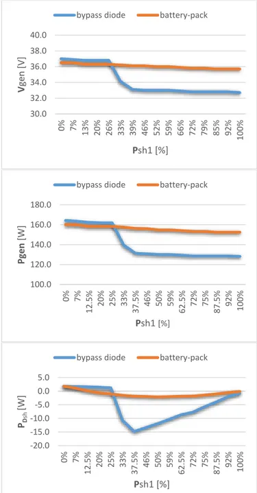
This very relevant aspect can be further investigated by additional experiments performed by increasing the number of the series-connected PV-cells to be protected by a single bypass diode. In this sense, we have tested different mini-modules based from five to eight series-connected PV-cells, always imposing a variable partial shading, Psh1, only on the single PV-cell number one of Figure 5. For the sake of brevity, we summarize the results of only the most critical case of eight PV-cells and they are reported in the Figure 7.
In order to make a clear comparative analysis, these last results are discussed in next section, after introducing also measurements obtained by inserting batteries just in place of the bypass diode.
4.3 Measurements with batteries
Now we present the results of measurements obtained by connecting in parallel to our mini-module two different wisely designed battery-packs. Figure 7 (brown lines) summarizes the results when the mini-module has eight series-connected PV-cells in parallel with which is inserted a battery-pack based on 2x4 AA NiMH 1.2V 2100 mAh batteries, whose rated voltage of 2.4V has been choose to be as close as possible to the MPP value of the mini-module. Figure 7 (brown lines) also contains results obtained by using a conventional bypass diode.
Benefits of using a battery-pack are well evident, either in terms of constancy of the whole output voltage, Vgen, or the
whole maximum generated power, Pgen, or the maximum
power dissipated on the shaded PV-cell, PDsh. In particular, it
is well evident that by using the battery-pack any issue related to the hot-spot phenomenon is completely eliminated; in fact, also in the very critical case in which a significant partial shading interests only a single PV-cell the maximum temperature of the shaded PV-cell was of only 30 °C as that of not shaded PV-cells. Obviously, these advantages are true in presence of a short-term partial shading which duration is fully compatible with the capacity of the utilized battery-pack.
The same test was also repeated for the case-study of a mini-module with four PV-cells and by using a battery-pack based on 1x4 AA NiMH 1.2V 2100 mAh batteries, which rated voltage of 1.2V is still close to the MPP value of the mini-module. For the sake of brevity, the results are not reported here but we can summarize that also in this case, all the already underlined advantages of using a battery-pack in place of a conventional bypass diode have been confirmed.
Concerning the insertion of a battery-pack directly in parallel to a group of series-connected PV-cells, in our opinion, it is still necessary to underline the great importance of
designing its rated voltage so that batteries do not disturb too much the power generation during major times characterized by no shadings. In this sense, as also mentioned in section 3.2, we have performed many experimental tests by connecting our battery-packs in parallel to a mini-module with a variable number of series-connected PV-cells. In particular, we have used a 1.2 V battery-pack in parallel to a mini-module with three, four and five PV-cells and also a 2.4V battery-pack in parallel to a mini-module with six, seven and eight PV-cells. For all cases, we have measured the maximum power generated by the mini-module (at the optimal load condition and with no shadings) without (SWbatt = OFF) and with (SWbatt
= ON) the insertion of the battery-pack; experiments was repeated at different times of some spring days in order to test battery effects under different irradiance and temperature working conditions of the PV-generators.
Figure 7. Comparison of measurement results on a
mini-module with eight series-connected PV-cells, when only one PV-cell is subject to a variable partial shading, Psh1; blue lines are obtained by using a conventional bypass diode while
brown lines are obtained by using a 2.4V battery-pack 30.0 32.0 34.0 36.0 38.0 40.0 0% 7% 13% 20% 26% 33% 39% 46% 52% 59% 66% 72% 79% 85% 92% 100% V gen [V] Psh1 [%]
bypass diode battery-pack
100.0 120.0 140.0 160.0 180.0 0% 7% 12.5% 20% 25% 33% 37.5% 46% 50% 59% 62.5% 72% 75% 87.5% 92% 100% Pgen [W] Psh1 [%]
bypass diode battery-pack
-20.0 -15.0 -10.0 -5.0 0.0 5.0 0% 7% 12.5% 20% 25% 33% 37.5% 46% 50% 59% 62.5% 72% 75% 87.5% 92% 100% PD sh [W] Psh1 [%]
About the utilization of the 2.4V battery-pack, for the sake of brevity we can simply summarize that the best matching was that with a mini-module based on seven series-connected PV-cells. With this solution, even the maximum loss of power was practically negligible, having been lower than 1% during all the test days. Anyway, the same 2.4V battery-pack has shown to be well adaptable also with six or eight series-connected PV-cells producing generation power loss still almost negligible (practically around 1%).
Very similar considerations can be developed also for the utilization of the 1.2V battery-pack inserted in parallel to a mini-module with three, four and five series-connected PV-cells; in this case, the best matching was that with four series-connected PV-cells.
Finally, by taking into account that the lower the number of series-connected PV-cells protected by a battery-pack (or by a bypass diode) the lower the probability to have a loss of power generation and hot-spot phenomena because of a partial shading affecting only a very small number of PV-cells, we can conclude that a 1.2V battery-pack connected in parallel to a group a four series-connected PV-cells can be a very good solution for coping with short-term, repetitive and critical partial shadings which can affect a very-low number of PV-cells of a PV-generator.
Obviously, the utilization of batteries connected in parallel to a PV-mini-module without a charge regulator invites to take into account also the issue of their reduced lifetime with respect to the major lifetime of PV-cells [17]. In this sense, by remembering that the main objective of our proposal is that of coping with repetitive short-term partial shadings, and taking into account also the charge/discharge properties of NiMH batteries [18], the lifetime of the battery pack could be optimized by matching as well as possible its capacity with the duration and the intensity of the partial shading to be coped, in order to avoid - daily - too high discharging currents and too deep discharge processes. If this is well done, from [18] one can expect that NiMH batteries can disclose a lifetime of about 3-4 years e this means that the battery packs should be substituted five-six times during the lifetime of its relative PV-mini-module. Nevertheless, for a more accuracy of a such simplified estimation, an experimental analysis on the long term is highly advisable for a next specific study.
5. CONCLUSIONS
Major issues of short-term, repetitive and critical partial shadings on a PV-field have been investigated by means of experimental tests. The use of conventional bypass diodes has been tested and measurements on our PV-generator prototype confirmed that, in case of critical shadings which interest only a very low number of PV-cells, conventional bypass diodes do not completely protect shaded PV-cells from hot-spot phenomena. In such cases, mini-battery-packs wisely designed in its rated voltage can be used profitably by inserting them directly in parallel to partially shaded PV-cells. They eliminate any hot-spot phenomenon and guarantee the generation of almost the maximum theoretical power together with an output voltage of the PV-generator almost constant and highly available.
REFERENCES
[1] Zhang Z, Wohlgemuth J, Kurtz S. (2013). The thermal reliability study of bypass diodes in photovoltaic modules. 2013 Photovoltaic Module Reliability Workshop, February 26‐27. Golden, Colorado. NREL/PO‐5200‐58225.
[2] Kim KA; Krein PT. (2015). Re-examination of photovoltaic hot spotting to show inadequacy of the bypass diode. IEEE Journal of Photovoltaics 2015. 5: 1435–1441.
https://doi.org/10.1109/JPHOTOV.2015.2444091 [3] Kurtz S, Whitfield K, TamizhMani G, Koehl M, Miller
D, Joyce J, Wohlgemuth J, Bosco N, Kempe M, Zgonena. (2011). Progress in Photovoltaics: Research and Applications T. Evaluation of High-temperature exposure of Photovoltaic Modules 19: 954–965. https://doi.org/10.1002/pip.1103
[4] Daniele Rossi, Martin Omaña, Daniele Giaffreda, Cecilia Metra. (2015). Modeling and detection of hotspot in shaded photovoltaic cells. IEEE Transactions on Very Large Scale Integration (VLSI) Systems 23(6). https://doi.org/10.1109/TVLSI.2014.2333064
[5] Silvestre S, Boronat A, Chouder A. (2009). Study of bypass diodes configuration on PV modules. Elsevier Applied Energy 86(9): 1632-1640. https://doi.org/10.1016/j.apenergy.2009.01.020
[6] Olalla C, Maksimovi´c D, Deline C. (2018). Mitigation of Hot-Spots in Photovoltaic Systems using Distributed Power Electronics Energies 11(4): 726. https://doi.org/10.3390/en11040726
[7] Patel H, Agarwal V. (2008). Industrial electronics, maximum power point tracking scheme for PV systems operating under partially shaded conditions. IEEE Trans.
55(4): 1689–1698.
https://doi.org/10.1109/TIE.2008.917118
[8] Pilawa-Podgurski Roberto CN, David J. Perreault (2013). Power electron, submodule integrated distributed maximum power point tracking for solar photovoltaic applications. IEEE Trans. 28(6): 2957–2967. https://doi.org/10.1109/TPEL.2012.2220861
[9] Shibin Qin, Robert CN, Pilawa-Podgurski, Sub-Module. (2013). Differential power processing for photovoltaic applications. Twenty-Eighth Annual IEEE Applied Power Electronics Conference and Exposition (APEC) p. 27. https://doi.org/10.1109/APEC.2013.6520193 [10] Luo HY, Wen HQ, Li XS, Jiang L, Hu YH. (2016).
Synchronous buck converter based low-cost and high-efficiency sub-module DMPPT PV system under partial shading conditions. Elsevier, Energy Conversion and Management Journal 126(15): 473–487. https://doi.org/10.1016/j.enconman.2016.08.034
[11] Khan W, Xiao. (2017). Review and qualitative analysis of submodule-level distributed power electronic solutions in PV power systems. Elsevier Renewable and Sustainable Energy Reviews 76: 516-528. https://doi.org/10.1016/j.rser.2017.03.073
[12] Carbone R, Maiolo GA. (2017). Maximizing benefits of batteries in residential grid-connected PV-plants subject to partial shading. Proceedings of the 6-th International Conference on Clean Electrical Power (ICCEP). https://doi.org/10.1109/ICCEP.2017.8004785
[13] Vitelli M. (2014). Progress in photovoltaics: Research and applications, On the necessity of joint adoption of
both distributed maximum power point tracking and central maximum power point tracking in PV systems. Wiley- Blackwell 22(9): 283–299. https://doi.org/10.1002/pip.2256
[14] Ramos-paja CA, Saavedra-montes AJ, Vitelli M. Dyna R. (2013). Distributed maximum power point tracking with overvoltage protection for PV systems (178): 141-150. Medellin, April 2013. ISSN 0012-7353. Freely available on the web at: 2346-2183. https://revistas.unal.edu.co/index.php/dyna/article/view/ 30596/44292
[15] Alonso R, Roman E, Sanz A, Santos VEM, Ibanez P. (2012). Analysis of inverter-voltage influence on distributed MPPT architecture performance. IEEE Transactions on Industrial Electronics 59(10): 3900-3907. https://doi.org/10.1109/TIE.2012.2189532 [16] Carbone R. (2009). IEEE International conference on
clean electrical power, grid-connected photovoltaic systems with energy storage. Capri - Italy. https://doi.org/10.1109/ICCEP.2009.5211967
[17] Xu CY, Xie CJ, Jiang F, Zhao JY. (2016). Design and implementation of the power battery management system of photovoltaic power generation based on bi-directional DCDC equalization control. IIETA Modelling, Measurement and Control A. 89(1): 156-172.
[18] Jossen A, Garche J, Sauer DU. (2004). Operation
conditions of batteries in PV applications. Solar Energy
76(6): 759-769.
https://doi.org/10.1016/j.solener.2003.12.013
NOMENCLATURE
I current, A
P power, W
Psh dimensionless partial shading
V voltage, V
SI solar irradiance, W.m-2
SW dimensionless circuit breaker Tc temperature of a pv-cell, °C
Subscripts
batt of battery
D of diode
Dsh dissipated by shaded pv-cells gen generated
mod of the pv-module mpp at maximum power point non-sh non shaded
sub-i i-th sub-module